

Page 1

Festo Didactic
8075265 de/en/fr
11/2017 R1.0
8075267
CPS-Gate
Industry 4.0
CP Lab
Betriebsanleitung
Operating instructions
Instructions de service
Page 2

Order number: 8075265
Revision level: 11/2017
Author: Andreas Hemminger
Layout: 11/2017, Frank Ebel
© Festo Didactic SE, Rechbergstraße 3, 73770 Denkendorf, Germany, 2017
Weitergabe sowie Vervielfältigung dieses Dokuments, Verwertung und Mitteilung seines Inhalts verboten,
soweit nicht ausdrücklich gestattet. Zuwiderhandlungen verpflichten zu Schadenersatz. Alle Rechte
vorbehalten, insbesondere das Recht, Patent-, Gebrauchsmuster- oder Geschmacksmusteranmeldungen
durchzuführen.
Hinweis
Soweit in dieser Betriebsanleitung nur von Lehrer, Schüler etc. die Rede ist, sind
selbstverständlich auch Lehrerinnen, Schülerinnen etc. gemeint. Die Verwendung
nur einer Geschlechtsform soll keine geschlechtsspezifische Benachteiligung sein,
sondern dient nur der besseren Lesbarkeit und dem besseren Verständnis der
Formulierungen.
Vorsicht
Diese Betriebsanleitung muss dem Anwender ständig zur Verfügung stehen.
Vor Inbetriebnahme muss die Betriebsanleitung gelesen werden.
Die Sicherheitshinweise müssen beachtet werden.
Bei Missachten kann es zu schweren Personen- oder Sachschaden kommen.
Deutsch _______________________________________________________________________________ 5
English _____________________________________________________________________________ 39
Français _____________________________________________________________________________ 73
Page 3

The reproduction, distribution and utilization of this document, as well as the communication of its content
to others without explicit authorization, are prohibited. Offenders will be held liable for damages. All rights
reserved, in particular the right to file patent, utility model and registered design applications.
Note
Where only pronouns such as he and him are used in these operating instructions,
these pronouns are of course intended to refer to both male and female persons.
The use of a single gender is not intended as gender discrimination, but simply to
aid readability and comprehension of the document and the formulations used.
Caution
These operating instructions must always be available to the user.
The operating instructions must be read before commissioning.
The safety instructions must be observed
Non-observance may result in severe personal injury or damage to property.
Page 4

Toute communication ou reproduction de ce document, sous quelque forme que ce soit, et toute
exploitation ou communication de son contenu sont interdites, sauf autorisation écrite expresse. Tout
manquement à cette règle expose son auteur au versement de dommages et intérêts. Tous nos droits sont
réservés, notamment pour le cas de l'attribution d'un brevet ou celui de l'enregistrement d'un modèle
d'utilité.
Nota
Les termes enseignant, étudiant, etc. employés dans les présentes instructions de
service désignent aussi, bien entendu, les enseignantes, étudiantes, etc. L'emploi
d'un seul genre ne saurait constituer une discrimination sexuelle, mais a
simplement pour but de faciliter la lecture et la compréhension de ce qui est dit.
Attention
Les instructions de service doivent être constamment à la disposition de
l'utilisateur.
Les instructions de service doivent avoir été lues avant la mise en service.
Se conformer aux consigne de sécurité.
Le non-respect peut entraîner de graves dommages corporels ou matériels.
Page 5

CPS Gate
© Festo Didactic 8075265 5
Inhalt
1 Allgemeine Voraussetzungen zum Betreiben der Geräte ____________________________________ 7
2 Piktogramme _______________________________________________________________________ 8
3 Bestimmungsgemäße Verwendung _____________________________________________________ 9
4 Für Ihre Sicherheit ________________________________________________________________ 10
4.1 Wichtige Hinweise ________________________________________________________________ 10
4.2 Verpflichtung des Betreibers ________________________________________________________ 10
4.3 Verpflichtung der Auszubildenden ___________________________________________________ 10
5 Arbeits- und Sicherheitshinweise ____________________________________________________ 11
6 Versionsinformation _______________________________________________________________ 13
7 Technische Daten _________________________________________________________________ 14
8 Zulassungen/Normen ______________________________________________________________ 16
9 Beschreibung ____________________________________________________________________ 17
10 Anschlüsse, Anzeige und Bedienelemente _____________________________________________ 18
10.1 Rückansicht ______________________________________________________________________ 18
10.2 Frontansicht _____________________________________________________________________ 18
10.3 Draufsicht _______________________________________________________________________ 19
10.4 Seitenansicht ____________________________________________________________________ 19
11 Installation ______________________________________________________________________ 20
11.1 Montage ________________________________________________________________________ 20
11.2 Demontage ______________________________________________________________________ 21
11.3 Elektrischer Anschluss _____________________________________________________________ 21
11.3.1 USB Schnittstelle _________________________________________________________________ 22
11.3.2 CAN Schnittstelle _________________________________________________________________ 23
11.3.3 Ethernet-Schnittstellen _____________________________________________________________ 24
11.3.4 Digitaleingänge ___________________________________________________________________ 25
11.3.5 Digitalausgänge, Spannungsversorgung ______________________________________________ 26
Page 6

CPS-Gate
6 © Festo Didactic 8075265
12 Magnetfeldsensoren _______________________________________________________________ 27
13 RFID ____________________________________________________________________________ 27
14 NFC ____________________________________________________________________________ 28
15 Betriebsartenschalter ______________________________________________________________ 28
16 Diagnoseanzeige _________________________________________________________________ 31
17 Anschlussdiagramm _______________________________________________________________ 34
18 Software ________________________________________________________________________ 34
18.1 CODESYS Programmierumgebung ____________________________________________________ 34
18.2 Web-Visualisierung ________________________________________________________________ 35
18.3 IP-Adresse _______________________________________________________________________ 36
19 Produktkennzeichnung ____________________________________________________________ 37
20 Wartung und Reinigung ____________________________________________________________ 37
21 Lagerung und Transport ____________________________________________________________ 37
22 Lieferumfang _____________________________________________________________________ 38
23 Zubehör, Ersatzteile _______________________________________________________________ 38
24 Entsorgung ______________________________________________________________________ 38
25 CE Konformitätserklärung __________________________________________________________ 38
Page 7

CPS-Gate
© Festo Didactic 8075265 7
1 Allgemeine Voraussetzungen zum Betreiben der Geräte
Allgemeine Anforderungen bezüglich des sicheren Betriebs der Geräte:
• In gewerblichen Einrichtungen sind die Unfallverhütungsvorschriften der DGUV Vorschrift 3 "Elektrische
Anlagen und Betriebsmittel" zu beachten.
• Der Labor- oder Unterrichtsraum muss durch einen Arbeitsverantwortlichen überwacht werden.
– Ein Arbeitsverantwortlicher ist eine Elektrofachkraft oder eine elektrotechnisch unterwiesene
Person mit Kenntnis von Sicherheitsanforderungen und Sicherheitsvorschriften mit aktenkundiger
Unterweisung.
Der Labor- oder Unterrichtsraum muss mit den folgenden Einrichtungen ausgestattet sein:
• Es muss eine NOT-AUS-Einrichtung vorhanden sein.
– Innerhalb und mindestens ein NOT-AUS außerhalb des Labor- oder Unterrichtsraums.
• Der Labor- oder Unterrichtsraum ist gegen unbefugtes Einschalten der Betriebsspannung bzw. der
Druckluftversorgung zu sichern.
– z. B. durch einen Schlüsselschalter
– z. B. durch abschließbare Einschaltventile
• Der Labor- oder Unterrichtsraum muss durch Fehlerstromschutzeinrichtungen (RCD) geschützt werden.
– Betreiben Sie elektrische Geräte (z. B. Netzgeräte, Verdichter, Hydraulikaggregate) nur in
Ausbildungsräumen, die mit einer Fehlerstromschutzeinrichtung ausgestattet sind.
– Als Fehlerstromschutzeinrichtung ist ein RCD-Schutzschalter mit Differenzstrom ≤ 30 mA, Typ B zu
verwenden.
• Der Labor- oder Unterrichtsraum muss durch Überstromschutzeinrichtungen geschützt sein.
– Sicherungen oder Leitungsschutzschalter
• Es dürfen keine Geräte mit Schäden oder Mängeln verwendet werden.
– Schadhafte Geräte sind zu sperren und aus dem Labor- oder Unterrichtsraum zu entnehmen.
– Beschädigte Verbindungsleitungen, Druckluftschläuche und Hydraulikschläuche stellen ein
Sicherheitsrisiko dar und müssen aus dem Labor- oder Unterrichtsraum entfernt werden.
Page 8
CPS-Gate
8 © Festo Didactic 8075265
2 Piktogramme
Dieses Dokument und die beschriebene Hardware enthalten Hinweise auf mögliche Gefahren, die bei
unsachgemäßem Einsatz des Systems auftreten können. Folgende Piktogramme werden verwendet:
Warnung
… bedeutet, dass bei Missachten schwerer Personen- oder Sachschaden entstehen
kann.
Vorsicht
… bedeutet, dass bei Missachten Personen- oder Sachschaden entstehen kann.
Warnung
… bedeutet, dass vor Montage-, Reparatur-, Wartungs- und Reinigungsarbeiten
das Gerät auszuschalten und der Netzstecker zu ziehen ist. Beachten Sie das
Handbuch, insbesondere alle Hinweise zur Sicherheit. Bei Missachten kann
schwerer Personen- oder Sachschaden entstehen.
Hinweis
… bedeutet, dass eine Handlungsanweisung für die bestimmungsgemäße
Verwendung des Gerätes zu befolgen ist. Ein Nichtbeachten kann zu
Funktionseinschränkungen führen.
Page 9

CPS-Gate
© Festo Didactic 8075265 9
3 Bestimmungsgemäße Verwendung
Das CPS-Gate von Festo Didactic ist nur zu benutzen:
• für die bestimmungsgemäße Verwendung im gewerblichen Lehr- und Ausbildungsbetrieb
• in sicherheitstechnisch einwandfreiem Zustand
Das CPS-Gate ist nach dem heutigen Stand der Technik und den anerkannten sicherheitstechnischen Regeln
gebaut. Dennoch können bei unsachgemäßer Verwendung Gefahren für Leib und Leben des Benutzers oder
Dritter und Beeinträchtigungen der Komponenten entstehen.
Das Lernsystem von Festo Didactic ist ausschließlich für die Aus- und Weiterbildung im Bereich
Automatisierung und Technik entwickelt und hergestellt. Das Ausbildungsunternehmen und/oder die
Ausbildenden hat/haben dafür Sorge zu tragen, dass die Auszubildenden die Sicherheitsvorkehrungen, die
in diesem Dokument beschrieben sind, beachten.
Festo Didactic schließt hiermit jegliche Haftung für Schäden des Auszubildenden, des
Ausbildungsunternehmens und/oder sonstiger Dritter aus, die bei Gebrauch/Einsatz dieses Gerätesatzes
außerhalb einer reinen Ausbildungssituation auftreten; es sei denn Festo Didactic hat solche Schäden
vorsätzlich oder grob fahrlässig verursacht.
Die in dieser Betriebsanleitung dokumentierte Steuerung CPS-Gate ist ausschließlich zum Einbau in das
Transportband von Festo Didactic vorgesehen.
Page 10

CPS-Gate
10 © Festo Didactic 8075265
4 Für Ihre Sicherheit
4.1 Wichtige Hinweise
Grundvoraussetzung für den sicherheitsgerechten Umgang und den störungsfreien Betrieb des CPS-Gates
ist die Kenntnis der grundlegenden Sicherheitshinweise und der Sicherheitsvorschriften. Diese
Betriebsanleitung enthält die wichtigsten Hinweise, um das Gerät sicherheitsgerecht zu betreiben.
Insbesondere die Sicherheitshinweise sind von allen Personen zu beachten, die mit dem CPS-Gate arbeiten.
Darüber hinaus sind die für den Einsatzort geltenden Regeln und Vorschriften zur Unfallverhütung zu
beachten.
4.2 Verpflichtung des Betreibers
Der Betreiber verpflichtet sich, nur Personen mit dem Gerät arbeiten zu lassen, die:
• mit den grundlegenden Vorschriften über Arbeitssicherheit und Unfallverhütung vertraut und in die
Handhabung des Gerätes eingewiesen sind,
• das Sicherheitskapitel und die Warnhinweise in dieser Betriebsanleitung gelesen und verstanden
haben.
Das sicherheitsbewusste Arbeiten des Personals soll in regelmäßigen Abständen überprüft werden.
4.3 Verpflichtung der Auszubildenden
Alle Personen, die mit Arbeiten an dem Gerät beauftragt sind, verpflichten sich, vor Arbeitsbeginn:
• das Sicherheitskapitel und die Warnhinweise in dieser Betriebsanleitung zu lesen,
• die grundlegenden Vorschriften über Arbeitssicherheit und Unfallverhütung zu beachten.
Warnung
Alle Sicherheitseinrichten der Maschine, die mit dem CPS-Gate verbunden ist, müssen
funktionsfähig sein.
Die elektrische Sicherheit der Maschine muss nachweislich gegeben sein.
Page 11

CPS-Gate
© Festo Didactic 8075265 11
5 Arbeits- und Sicherheitshinweise
Allgemein
• Die Auszubildenden dürfen nur unter Aufsicht einer Ausbilderin/eines Ausbilders an den Schaltungen
arbeiten.
• Beachten Sie die Angaben der Datenblätter zu den einzelnen Komponenten, insbesondere auch alle
Hinweise zur Sicherheit!
• Störungen, die die Sicherheit beeinträchtigen können, dürfen nicht erzeugt werden.
• Tragen Sie Ihre persönliche Schutzausrüstung (Schutzbrille, Sicherheitsschuhe), wenn Sie an den
Schaltungen arbeiten.
Elektrik
• Lebensgefahr bei unterbrochenem Schutzleiter!
– Der Schutzleiter (grün-gelb) darf weder außerhalb noch innerhalb des Geräts unterbrochen werden.
– Die Isolierung des Schutzleiters darf weder beschädigt noch entfernt werden.
• Lebensgefahr durch Reihenschaltung von Netzteilen!
Berührungsspannungen > 25 V AC bzw. > 60 V DC sind nicht zulässig.
Spannungen > 50 V AC bzw. 120 V DC können bei Berührung tödlich sein.
– Schalten Sie keine Spannungsquellen hintereinander.
• Lebensgefahr durch elektrischen Schlag!
Schützen Sie die Ausgänge der Netzteile (Ausgangsbuchsen/-klemmen) und daran angeschlossene
Leitungen vor direkter Berührung.
– Verwenden Sie nur Leitungen mit ausreichender Isolation bzw. Spannungsfestigkeit.
– Verwenden Sie Sicherheitssteckbuchsen mit berührungssicheren Kontaktstellen.
• Spannungsfrei schalten!
– Schalten Sie die Spannungsversorgung aus, bevor Sie an der Schaltung arbeiten.
– Beachten Sie, dass elektrische Energie in einzelnen Komponenten gespeichert sein kann.
Informationen hierzu finden Sie in den Datenblättern und Bedienungsanleitungen der
Komponenten.
– Vorsicht!
Kondensatoren im Gerät können noch geladen sein, selbst wenn das Gerät von allen
Spannungsquellen getrennt wurde.
• Herstellen bzw. Abbauen von elektrischen Anschlüssen
– Stellen Sie elektrische Anschlüsse nur in spannungslosem Zustand her.
– Bauen Sie elektrische Anschlüsse nur in spannungslosem Zustand ab.
Page 12

CPS-Gate
12 © Festo Didactic 8075265
• Die zulässigen Strombelastungen von Leitungen und Geräten dürfen nicht überschritten werden.
– Vergleichen Sie stets die Strom-Werte von Gerät, Leitung und Sicherung.
– Benutzen Sie bei Nichtübereinstimmung eine separate vorgeschaltete Sicherung als
entsprechenden Überstromschutz.
• Verwenden Sie für die elektrischen Anschlüsse nur Verbindungsleitungen mit Sicherheitssteckern.
• Verlegen Sie Verbindungsleitungen so, dass sie nicht geknickt oder geschert werden.
• Verlegen Sie Leitungen nicht über heiße Oberflächen.
– Heiße Oberflächen sind mit einem Warnsymbol entsprechend gekennzeichnet.
• Achten Sie darauf, dass Verbindungsleitungen nicht dauerhaft unter Zug stehen.
• Wenn in den Technischen Daten nicht anders angegeben, besitzt das Gerät keine integrierte Sicherung.
• Ziehen Sie beim Abbauen der Verbindungsleitungen nur an den Sicherheitssteckern, nicht an den
Leitungen.
• Bei
– sichtbarer Beschädigung,
– defekter Funktion,
– unsachgemäßer Lagerung oder
– unsachgemäßem Transport
ist kein gefahrloser Betrieb des Geräts mehr möglich.
– Schalten Sie sofort die Spannung ab.
– Schützen Sie das Gerät vor unbeabsichtigtem Wiedereinschalten.
Pneumatik
• Drucklos schalten!
– Schalten Sie die Druckluftversorgung aus, bevor Sie an der Schaltung arbeiten.
– Prüfen Sie mit Druckmessgeräten, ob die komplette Schaltung drucklos ist.
– Beachten Sie, dass in Druckspeichern Energie gespeichert sein kann. Informationen hierzu finden
Sie in den Datenblättern und Bedienungsanleitungen der Komponenten.
• Überschreiten Sie nicht den zulässigen Druck von 600 kPa (6 bar).
• Schalten Sie die Druckluft erst ein, wenn Sie alle Schlauchverbindungen hergestellt und gesichert
haben.
• Entkuppeln Sie keine Schläuche unter Druck.
• Verletzungsgefahr beim Einschalten von Druckluft!
Zylinder können selbsttätig aus- und einfahren.
• Unfallgefahr durch ausfahrende Zylinder!
– Platzieren Sie pneumatische Zylinder immer so, dass der Arbeitsraum der Kolbenstange über den
gesamten Hubbereich frei ist.
– Stellen Sie sicher, dass die Kolbenstange nicht gegen starre Komponenten des Aufbaus fahren
kann.
• Unfallgefahr durch abspringende Schläuche!
– Verwenden Sie kürzest mögliche Schlauchverbindungen.
– Beim Abspringen von Schläuchen: Schalten Sie die Druckluftzufuhr sofort ab.
Page 13

CPS-Gate
© Festo Didactic 8075265 13
• Schalten Sie vor dem Schaltungsabbau die Druckluftversorgung ab.
• Lärm durch ausströmende Druckluft!
– Lärm durch ausströmende Druckluft kann schädlich für das Gehör sein. Reduzieren Sie den Lärm
durch den Einsatz von Schalldämpfern oder tragen Sie einen Gehörschutz, falls der Lärm sich nicht
vermeiden lässt.
– Alle Abluftanschlüsse der Komponenten der Gerätesätze sind mit Schalldämpfern versehen.
Entfernen Sie diese Schalldämpfer nicht.
Vorsicht!
Durch unsachgemäße Reparaturen oder Veränderungen können unvorhersehbare
Betriebszustände entstehen. Führen Sie keine Reparaturen am Gerät durch.
6 Versionsinformation
Die Beschreibung bezieht sich auf folgende Versionen:
– Festo Steuerung CPS-Gate Version 1.0/0
– Softwarepaket CODESYS V3 provided by Festo (pbF)
Die Beschreibung enthält Informationen zur Funktion, Montage, Installation und Inbetriebnahme des CPSGates
Version
Beschreibung
V1.0/0
Freigegebene Erstserie
Version Betriebsanleitung
Version
Beschreibung
V1.0
Freigegebene Erstserie
V1.1
Korrektor Technischer Daten
Ergänzung FCC / IC Hinweis
Neue Version der Frontbeschriftung
Korrektur Betriebswahlschalter
Page 14

CPS-Gate
14 © Festo Didactic 8075265
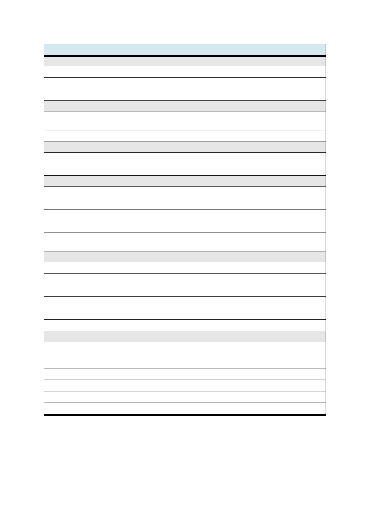
7 Technische Daten
Technische Daten
CPU
Prozessor
Cortex-A9, Single Core, 800MHZ
Echtzeituhr
Vorhanden, mittels Gold-Cap bis zu 4 Wochen gepuffert
Speicher
4 GByte RAM, 1 GByte Flash
Pufferung
1 MByte Retain Daten im Flash
Software / Funktionalität
Betriebssystem
Embedded Linux 4.00
SPS Programmierung
CODESYS V3 (CS3)
HMI Programmierung
CODESYS V3 WebVisu (WV)
Ethernet TCP-Modbus Client oder Server
Realisierbar über IEC-Bibliothek
EtherCAT Master (optional)
Integriert in CODESYS V3 (CS3)
CANopen Master
Realisierbar über IEC-Bibliothek
OPC-UA (optional)
Integriert in CODESYS V3 (CS3)
Elektrische Schnittstellen
X1
USB-Diagnose (USB Device Buchse Typ B)
X2
CAN nach ISO11898 mit galvanischer Trennung, RJ45
X3 … X5
Ethernet-Schnittstellen, 100BASE-T, RJ45 mit 3-fach Switch-Funktionalität
X6
Digitaleingänge DI0, DI1
Eingangsspannung
Frequenz max.
Eingangsverzögerung
Überspannung
Verlustleistung
Min. Spannung High
Max. Spannung Low
24 VDC, EN 61131-2 Typ 1
100 Hz
≤ 10 ms
33 V
0,2 Watt pro Eingang;
24 mA Versorgung pro Eingang
15 V
5 V
X7
Digitaleingänge DI2, DI3
X9
Digitaleingänge DI4, DI5
X10
Digitaleingänge DI6, DI7
X8
Digitalausgänge DO0, DO1
Spannungsversorgung
digital Ein-/Ausgänge
Ausgangsspannung
Ausgangsstrom
Summenstrom
(lt. DIN)
Ohmsche Last
Schaltfrequenz
Ohm/Induktiv
Kurzschluss- /
thermischer Schutz
Strombegrenzung
Schmelzsicherung
Verlustleistung
24 VDC, EN 61131-2 Typ 1
0,5 A
Max. 2 A (bei 50% ED)
48 W nominal
100 Hz
0,7 A pro Kanal
2 A für Summenstrom
0,2 W pro Ausgang
X11
Digitalausgänge DO2, DO3
Spannungsversorgung CPU
Page 15
CPS-Gate
© Festo Didactic 8075265 15
Technische Daten (Fortsetzung)
Funkschnittstellen
NFC für die Konfiguration
4 kBit EEPROM, ISO 15693
RFID für Logistikfunktion
Reader / Writer 13,56 MHz Multiprotokoll mit integrierter Antenne
RFID Sendeleistung
49,83 dBµV/m @ 3m (-45,4 dBm ±2dBm)
Interne Sensoren / Aktoren
Hall Sensoren
4x Magnetfeldsensoren für Erkennung des Werkstückträgers
2x Sensoren für die Lageerkennung des Stopper.
Stopper
Pneumatischer Stopper Applikator, 3 mm Luftanschluss, max. 600 kPa (6 bar)
Bedien- und Anzeigeelemente
S1
Betriebsartenschalterschalter (BAS) für SPS
Status LEDs
36 LEDs für Betriebs- und Statusmeldungen
Mechanische Daten
Außenmaße (B x H x T)
120 x 144 x 30 mm
Gewicht
Ca. 660 g
Gehäuse
Aluminiumgehäuse mit Kunststoffabdeckung
Schutzart
IP20, nach EN 60529
Montage
40 mm Aluminiumstrangpressprofil,
Gerät muss thermisch leitend mit der Maschinenstruktur verbunden sein.
Betriebsbedingungen
Betriebstemperatur
5 °C …40 °C
Lagertemperatur
-20 °C …70 °C
Relative Luftfeuchtigkeit Betrieb
10 % …5 % nicht kondensierend
Relative Luftfeuchtigkeit Lager
5 %…85 % nicht kondensierend
Kühlung
Passiver Kühlkörper, Konvektion muss gegeben sein
Betrieb des Gerätes
Verwendung nur in Innenräumen, bis 3000 m über Normalnull
Elektrische Anschlussdaten
Versorgungspannung
24 VDC (20,4 V….28,8 V), verpolgeschützt
Versorgung nur durch SELV/PELV Netzteil mit Energiebegrenzung,
Vorsicherung max. 4 AT
Leistungsaufnahme
Max. 60 W
Leistungsaufnahme Ventile
4x 1 W (4x 40 mA)
Stromaufnahme CPU
240 mA
Stromaufnahme Digitalausgänge
4x 500 mA
Page 16

CPS-Gate
16 © Festo Didactic 8075265
8 Zulassungen/Normen
Zulassungen
CE Kennzeichnung nach
Radio Equipment Device (RED) – Richtlinie
Spektrum: ETSI EN 300330
Safety EN 61131-2
EMV ETSI EN 300489-1, ETSI EN 301489-3
EN 61131-2
RoHS Richtlinie
EN 50581
RCM
Marktzulassung Australien
FCC
FCC ID: 2AMRG-CPSGATE
IC
IC: 22929-CPSGATE
Page 17

CPS-Gate
© Festo Didactic 8075265 17
9 Beschreibung
Das CPS-Gate ist ein multifunktionales Steuergerät mit SPS Funktionalität. Auf einem leistungsfähigen
Rechenkern läuft die CODESYS Programmierumgebung mit umfangreichen Bibliotheksfunktionen.
Eine Vielzahl modernen Industrie- und Mediaschnittstellen ermöglichen den Einsatz in einer Industrie 4.0
Umgebung. Steuerung, Sensoren, Aktoren und Kommunikationsschnittstellen sind im CPS-Gate vereinigt
und befinden sich direkt an der Feldapplikation.
Über die drahtlose NFC-Schnittstelle kann das Gerät für die Applikation durch ein Mobilgerät parametriert
werden. Die RFID-Schnittstelle erlaubt das permanente lesen/schreiben von Informationen des
Werkstückträgers. Zusätzlich können die Werkstückträger mit Magneten codiert werden, die von den
4 integrierten Magnetfeldsensoren erkannt werden. Der pneumatische Stopper kann die Werkstückträger
stoppen oder für den Weitertransport freigeben. Die Position der Kolbenstange des Stoppers wird durch 2
weitere Sensoren erkannt.
Blockdiagramm CPS-Gate
Page 18
CPS-Gate
18 © Festo Didactic 8075265
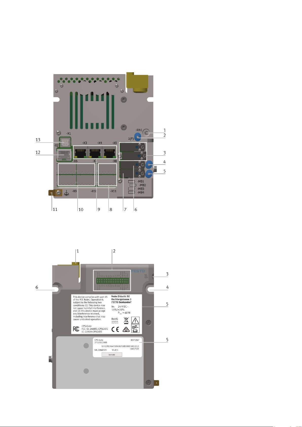
10 Anschlüsse, Anzeige und Bedienelemente
10.1 Rückansicht
1
Abluftdrossel für Ventile 1, 2
2
Druckluftanschluss für Ventile 1 … 4
3
Ventilspulen -MB1, -MB2 für internen
Stopper
4
Arbeitsanschluss von Ventil 3
5
Arbeitsanschluss von Ventil 4
6
Ventilspule -MB3
7
Ventilspule -MB4
8
Anschlüsse -X8, -X11 für digitale
Ausgänge und Versorgungsspannungen
9
Anschlüsse -X3 … -X5 für Ethernet
10
Anschlüsse -X6, -X7, -X9, -X10 für
digitale Eingänge
11
Funktionserdanschluss
12
CAN-Anschluss -X2
13
USB-Anschluss -X1
10.2 Frontansicht
1
Stopper
2
Diagnoseanzeige
3
Betriebsartenschalter
4
Montagepunkt
5
Typenschild
6
Montagepunkt
Page 19

CPS-Gate
© Festo Didactic 8075265 19
10.3 Draufsicht
1
Position Magnetfeldsensor -BE1
2
Position Magnetfeldsensor -BE2
3
Position Magnetfeldsensor -BE3
4
Position Magnetfeldsensor -BE4
5
Position RFID Antenne
6
Position NFC Antenne
10.4 Seitenansicht
1
Alternativer Druckluftanschluss 11 (P)
Page 20

CPS-Gate
20 © Festo Didactic 8075265
11 Installation
Warnung
Das Gerät darf nicht zur Ansteuerung von sicherheitsrelevanten Einrichtungen
verwendet werden. Eine funktionale Sicherheit kann nicht gewährleistet werden!
Vorsicht
Vor der Installation und Inbetriebnahme muss die Betriebsanleitung sorgfältig gelesen
und befolgt werden. Es sind die einschlägigen Sicherheitsvorschriften zu beachten.
Gleichen Sie die Baugruppe vor Inbetriebnahme der Raumtemperatur an. Bei Betauung
dürfen Sie das Gerät erst einschalten, nachdem es absolut trocken ist.
Um eine Überhitzung des Gerätes im Betrieb zu verhindern,
– darf das Gerät keiner direkten Sonnenbestrahlung ausgesetzt werden,
– dürfen die Lüftungsschlitze im Gehäuse durch den Einbau nicht verdeckt werden,
– ist auf ausreichende Luftzirkulation zu achten.
11.1 Montage
Das Gerät wird am Aluminiumrechteckrohrprofil des Transportbandes angeschraubt. Die Montageteile
liegen der Lieferung bei. Das Gerät darf nur senkrecht eingebaut werden, so dass der Stopperzylinder eine
Vertikalbewegung macht. Es ist darauf zu achten, dass der Aluminiumkörper des Gerätes im Bereich des
Profils flächig aufliegt.
An der Gerätrückseite befinden sind die elektrischen Anschlüsse. Diese müssen nach der Montage
zugänglich sein.
Das Gerät wird an den Montagepunkten 1 und
2 an das 40 mm Aluminiumprofil geschraubt.
Dafür liegen die zwei Schrauben DIN 912
M5x20 mm bei.
Im Aluminiumprofil sind an den
entsprechenden Stellen die beiliegenden
Nutensteine einzusetzen.
Page 21
CPS-Gate
© Festo Didactic 8075265 21
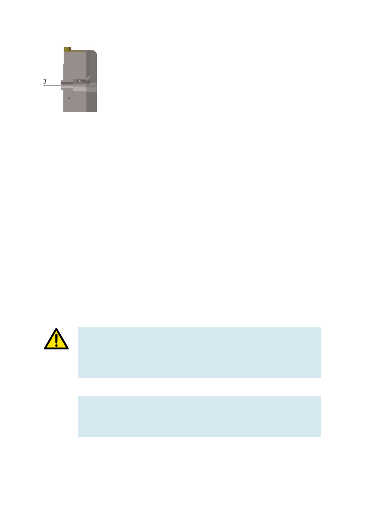
Es ist darauf zu achten, dass die überstehende
Lippe (3) in die Längsnut des
Aluminiumprofiles ragt.
11.2 Demontage
Die Demontage erfolgt ausschließlich im spannungslosen Zustand. Alle Zusatzgeräte, die mit dem CPS-Gate
verbunden sind, müssen spannungslos sein.
Alle elektrischen Anschlüsse werden vom Gerät getrennt. Anschließend wir das Gerät abgeschraubt. Im Falle
der Entsorgung ist das Gerät fachgerecht zu entsorgen. Dies kann über die kommunale Sammelstelle
erfolgen oder dem Hersteller übergeben werden.
Bei Weiterverwendung müssen alle elektrischen Anschlüsse mit der entsprechenden Abdeckkappe
geschlossen werden
11.3 Elektrischer Anschluss
Die erforderlichen elektrischen Anschlüsse werden im spannungslosen Zustand gesteckt. Nicht benutzte
Anschlüssen werden mit den entsprechenden Abdeckkappen geschlossen.
Vor der Inbetriebnahme müssen alle elektrischen Signale mit einer Gegenstelle verbunden sein.
Vorsicht
Das Gerät verfügt über einen Funktionserdanschluss (FE). Dieser muss vor
Inbetriebnahme dauerhaft und niederohmig mit dem Schutzleitersystem der Installation
verbunden sein.
Hinweis
Als FE-Anschlussleitung sind hochflexible Kupfergeflecht-Bänder geeignet. Massivadern
sind nicht empfehlenswert.
Page 22
CPS-Gate
22 © Festo Didactic 8075265
Vorsicht
Das Gerät darf nur durch ein SELV/PELV Netzteil mit Energiebegrenzung versorgt
werden. Die maximale Vorsicherung ist 4 AT.
Hinweis
Um Störeinkopplungen zu vermeiden, darf die Länge der DC-Versorgungsleitung
maximal 3 m betragen.
Alle Anschlussleitungen sollten von störungsbehafteten Leitungen (Starkstrom,
Motorleitungen) getrennt verlegt werden um eine Störeinkopplung zu vermeiden.
Hinweis
An der Geräteoberseite befinden sich integrierte Antennen für die RFID- und
NFC-Kommunikation. Diese dürfen nicht abgedeckt werden.
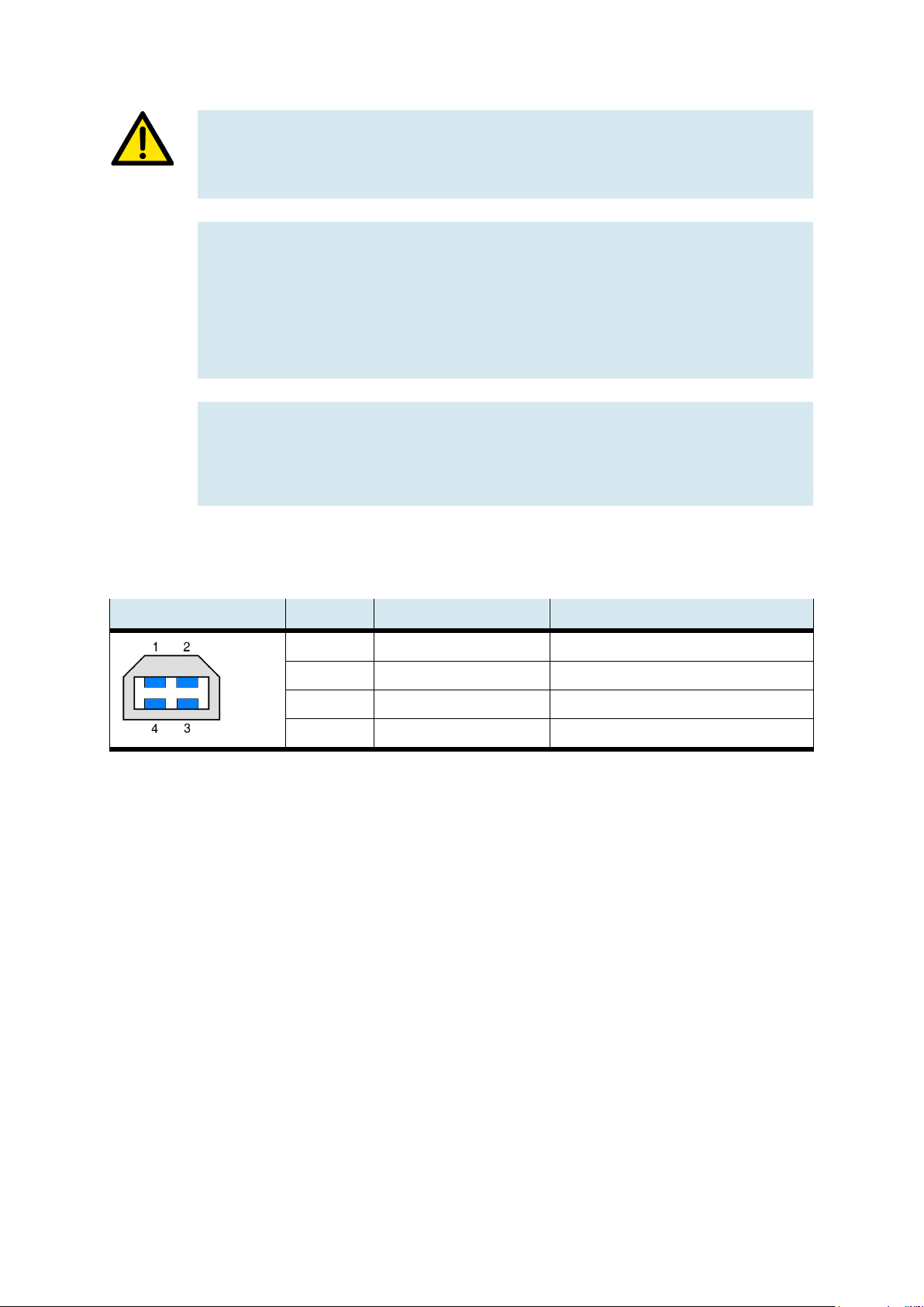
11.3.1 USB Schnittstelle
USB, -X1
PIN
Belegung
Funktion
1
+5 V (max. 500 mA)
Versorgungsspannung
2
Data-
3 Data+
4 GND 5 V (Signal Masse)
Versorgungsspannung
Der USB-Anschluss muss seine Betriebsspannung (5 VDC) von der Kommunikationsgegenstelle erhalten,
um eine Kommunikation zu ermöglichen.
Bei Kommunikationsstörungen wird eine galvanische Trennung zwischen dem USB Anschluss und dem
externen USB Gerät empfohlen, um die Masseschleife zu unterbrechen. Dazu kann ein entsprechender
USB-Hub verwendet werden.
Page 23
CPS-Gate
© Festo Didactic 8075265 23
11.3.2 CAN Schnittstelle
Diese Schnittstelle ist über einen 8-poligen RJ45-Stecker herausgeführt. Sie ist galvanisch von der
Versorgungsspannung des Gerätes getrennt.
CAN, -X2
PIN
Belegung
1
2
3
4
5
6
7
8
Shld
CAN-H
CAN-L
GND (Signal Ground für CAN) HF-Kopplung auf FE (1 MOhm || 22 nF)
NC
NC
NC
NC
NC
Schirm, HF-Kopplung auf FE (1 MOhm || 22 nF)
Hinweise
– Die nicht belegten Anschlusspins 4 … 8 dürfen von der Gegenstelle nicht
verwendet werden.
– Prüfen Sie, ob aufgrund der Gesamtbusstruktur ein externer Abschlusswiderstand
benötigt wird. In der Regel befinden sich diese Abschluss-/
Terminierungswiderstände am Anfang und am Ende des Buskabels.
Der Widerstandswert beträgt typisch 120 Ohm.
– Verwenden Sie eine verdrillte, geschirmte 2-Draht Leitung.
Hinweis
Bei fehlerhafter Installation und hohen Übertragungsraten können
Datenübertragungsfehler durch Signalreflexionen und Signaldämpfungen auftreten.
Ursachen für Übertragungsfehler können sein:
– fehlender Abschlusswiderstand zwischen CAN_L (Pin 2) und CAN_H (Pin 1),
– fehlerhafter Schirmanschluss,
– Abzweigungen,
– große Entfernungen,
– ungeeignete Leitungen.
Page 24

CPS-Gate
24 © Festo Didactic 8075265
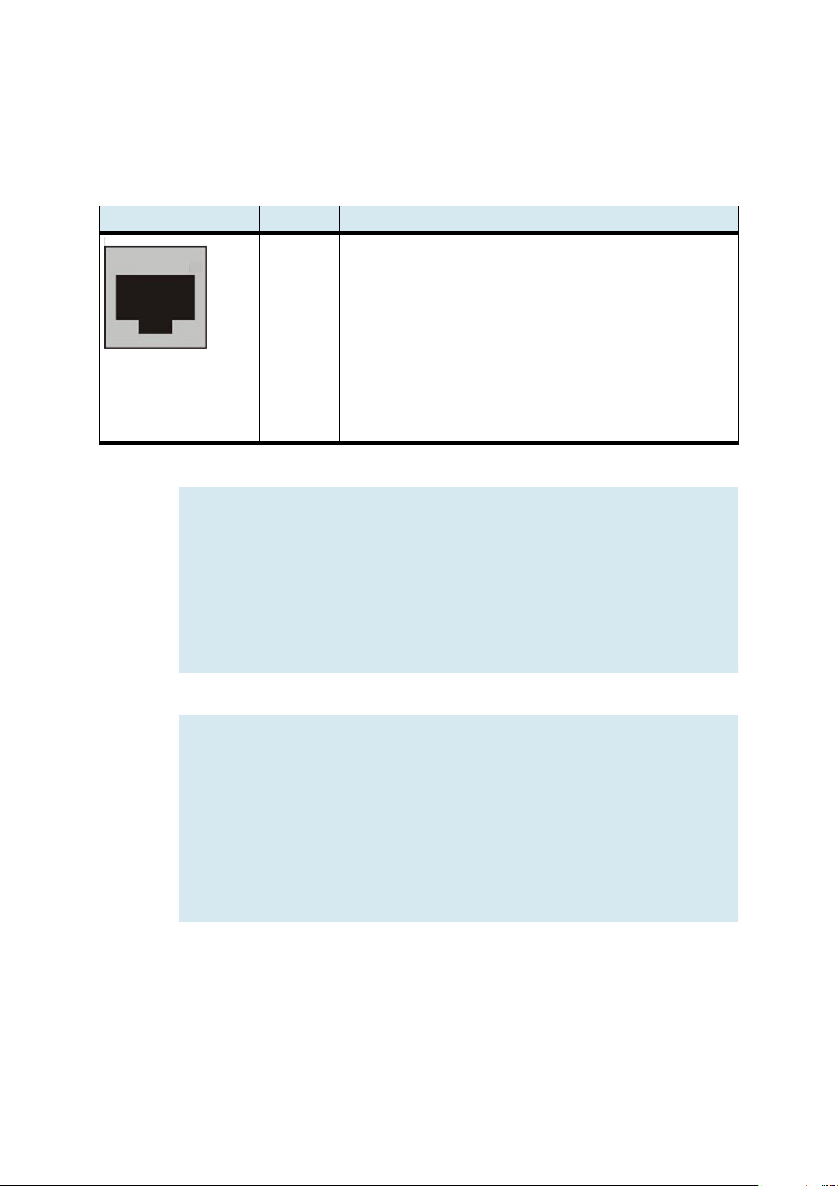
11.3.3 Ethernet-Schnittstellen
Die Ethernet-Schnittstellen sind als RJ45-Buchse mit Switch Funktionalität ausgeführt.
Der integrierte 10/100 MBit Ethernet-Switch unterstützt Auto-MDI(X). Es können sowohl Crossover- als auch
Patchkabel verwendet werden.
Die Anschlüsse und Leitungen entsprechen CAT 5. Es ist sicherzustellen, dass der Ethernet-Anschluss an der
Gegenstelle geerdet ist.
Der Funktionserdanschluss des CPS-Gates muss geerdet werden.
Schnittstellen -X3, -X4, -X5
PIN
Belegung
Funktion
1
TX+
Transmit Data +
2
TX-
Transmit Data -
3
RX+
Receive Data +
4
n.c.
keine
5
n.c.
keine
6
RX-
Receive Data -
7
n.c.
keine
8
n.c.
Keine
Shld
Schirmgehäuse
Verbunden mit FE
Ethernet
3x RJ45 (switched)
Übertragungsmedium
Mindestens Twisted Pair SF-UTP, 100 Ω, CAT 5,
100 m maximale Leitungslänge
Übertragungsrate
10/100 Mbit/s
Protokolle
DHCP, DNS, FTP, HTTP, HTTPS, SSH
Page 25

CPS-Gate
© Festo Didactic 8075265 25
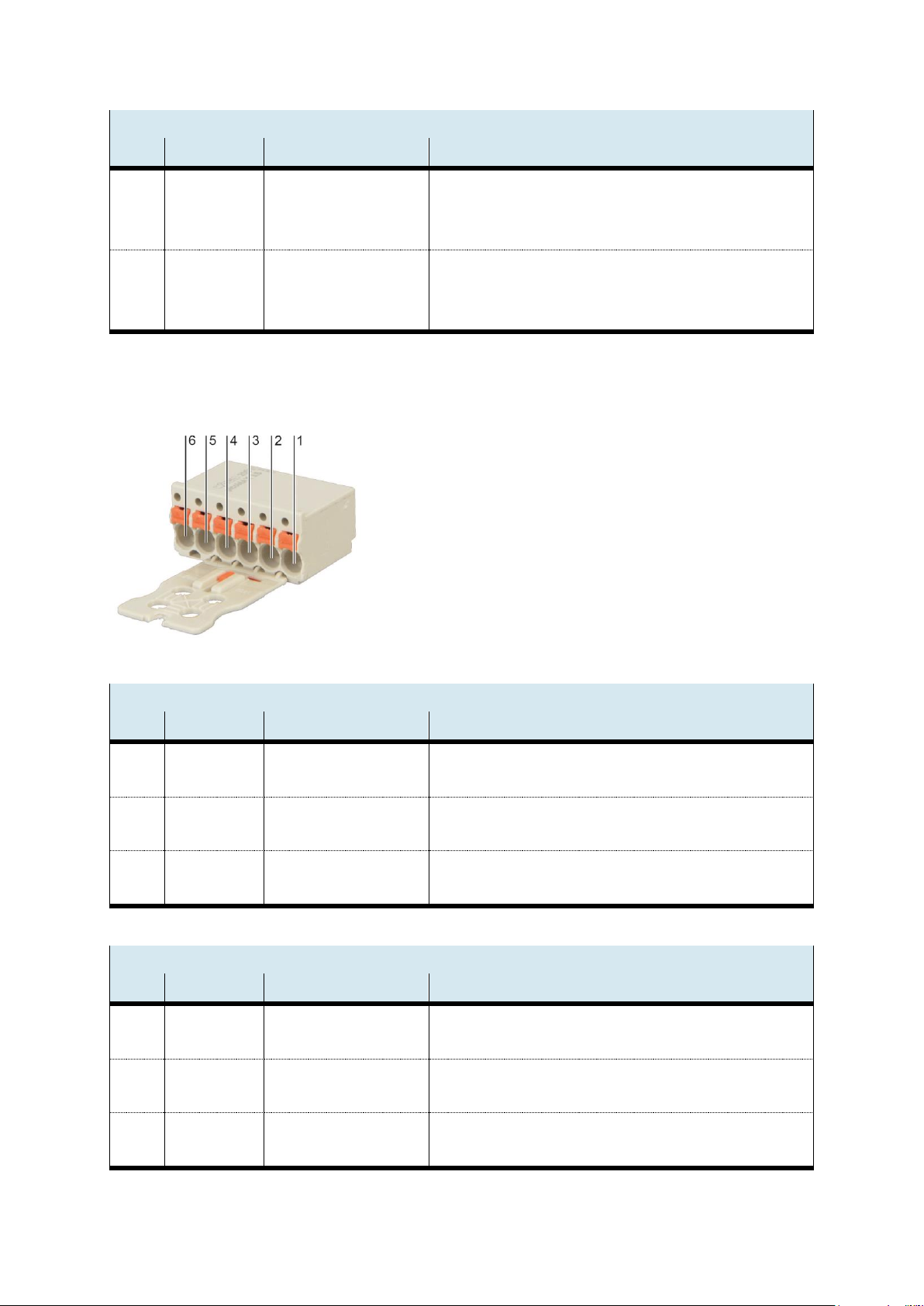
11.3.4 Digitaleingänge
Anschlusspins für die Schnittstelle -X6 … -X11
Hersteller: Wago,
Bestellnummer: 2091-1106/002-000
-X6, Digitale Eingänge DI0, DI1
PIN
Benennung
Funktion
Hinweis
1
2
3
DI0
GND
+24 V
Digitaler Eingang 0
Bezugsmasse
Versorgungsspannung
Galvanisch getrennt
Verbunden mit -X8, 1+3
Verbunden mit -X8, 2. Für Sensorversorgung
4
5
6
DI1
GND
+24 V
Digitaler Eingang 1
Bezugsmasse
Versorgungsspannung
Galvanisch getrennt
Verbunden mit -X8, 1+3
Verbunden mit -X8, 2. Für Sensorversorgung
-X7 Digitale Eingänge DI2, DI3
PIN
Benennung
Funktion
Hinweis
1
2
3
DI2
GND
+24 V
Digitaler Eingang 2
Bezugsmasse
Versorgungsspannung
Galvanisch getrennt
Verbunden mit -X8, 1+3
Verbunden mit -X8, 2. Für Sensorversorgung
4
5
6
DI3
GND
+24 V
Digitaler Eingang 3
Bezugsmasse
Versorgungsspannung
Galvanisch getrennt
Verbunden mit -X8, 1+3
Verbunden mit -X8, 2. Für Sensorversorgung
-X9, Digitale Eingänge DI4, DI5
PIN
Benennung
Funktion
Hinweis
1
2
3
DI4
GND
+24 V
Digitaler Eingang 4
Bezugsmasse
Versorgungsspannung
Galvanisch getrennt
Verbunden mit -X8, 1+3
Verbunden mit -X8, 2. Für Sensorversorgung
4
5
6
DI5
GND
+24 V
Digitaler Eingang 5
Bezugsmasse
Versorgungsspannung
Galvanisch getrennt
Verbunden mit -X8, 1+3
Verbunden mit -X8, 2. Für Sensorversorgung
Page 26
CPS-Gate
26 © Festo Didactic 8075265
-X10, Digitale Eingänge DI6, DI7
PIN
Benennung
Funktion
Hinweis
1
2
3
DI6
GND
+24 V
Digitaler Eingang 6
Bezugsmasse
Versorgungsspannung
Galvanisch getrennt
Verbunden mit -X8, 1+3
Verbunden mit -X8, 2. Für Sensorversorgung
4
5
6
DI7
GND
+24 V
Digitaler Eingang 7
Bezugsmasse
Versorgungsspannung
Galvanisch getrennt
Verbunden mit -X8, 1+3
Verbunden mit -X8, 2. Für Sensorversorgung
11.3.5 Digitalausgänge, Spannungsversorgung
Anschlusspins für die Schnittstelle -X8, -X11
Typ: Wago-2091-1406
-X8, Digitale Ausgänge DO0, DO1, Versorgungsspannung digital Schnittstellen
PIN
Benennung
Funktion
Hinweis
1 2 GND
+24V
Bezugsmasse
Versorgungsspannung
GND-Einspeiseklemme für digitale Schnittstellen
+24 V Einspeiseklemme für digitale Schnittstellen
3 4 GND
DO1
Bezugsmasse
Digitaler Ausgang 1
Verbunden mit -X8, 1. Bezugspotential für DO1
galvanisch getrennt von CPU Versorgung
5 6 GND
DO0
Bezugsmasse
Digitaler Ausgang 0
Verbunden mit -X8, 1. Bezugspotential für DO0
galvanisch getrennt von CPU Versorgung
-X11, Digitale Ausgänge DO2, DO3, Versorgungsspannung CPU
PIN
Benennung
Funktion
Hinweis
1 2 GND_CPU
+24V_CPU
Bezugsmasse
Versorgungsspannung
GND-Einspeiseklemme für CPU
+24 V Einspeiseklemme für CPU
3 4 GND
DO3
Bezugsmasse
Digitaler Ausgang 3
Verbunden mit -X8, 1. Bezugspotential für DO1
galvanisch getrennt von CPU Versorgung
5 6 GND
DO2
Bezugsmasse
Digitaler Ausgang 2
Verbunden mit -X8, 1. Bezugspotential für DO0
galvanisch getrennt von CPU Versorgung
Page 27

CPS-Gate
© Festo Didactic 8075265 27
12 Magnetfeldsensoren
An der Geräteoberseite befinden sich vier integrierte Magnetfeldsensoren für die Erkennung des
Werkstückträgers. Die Positionen der Sensoren -BE1 … -BE4 sind markiert. Die Magnete müssen so montiert
werden, dass der Südpol in Richtung des Sensors ausgerichtet ist.
13 RFID
Im CPS-Gate ist ein RFID (Radio Frequency IDentification) Schreib-/Leseeinheit eingebaut. Damit kann ein
13,56 MHz RFID-Tag (IEC 15693), der am Werkstückträger montiert ist, gelesen und beschrieben werden.
Die RFID Antenne befindet sich an der Oberseite des CPS-Gates und ist markiert. Die Tags sollten sich im
Abstand von 1 … 30 mm parallel zur Geräteoberseite befinden um ein zuverlässiges lesen/schreiben zu
ermöglichen.
Hinweis
Das RFID Modul arbeitet mit induktiver Signalkopplung. Jede Art von Metall in
Antennennähe beeinflusst die Signalübertragung.
– Vermeiden Sie metallische Materialien im Bereich der Antenne und des Tags
– Vermeiden Sie die Anordnung mehrerer Tags im Antennenbereich
Page 28

CPS-Gate
28 © Festo Didactic 8075265
14 NFC
Das integrierte NFC-Modul (Near Field Communication) ermöglicht die Parametrierung des Gerätes für die
Applikation. Die Daten werden in einem remanenten, 512 Byte großen Speicher abgelegt. Seitens CODESYS
ist der Schreib-/Lesezugriff auf diesen Speicher ebenfalls möglich.
Die NFC Antenne des CPS-Gates befindet sich an der Geräteoberseite und ist markiert. Das Mobilgerät sollte
in einer Entfernung von bis zu 10 cm herangeführt werden, um eine Kommunikation aufzubauen.
Gegebenenfalls muss die Einbaulage der NFC Antenne des externen Gerätes anhand der technischen
Unterlagen bestimmt werden.
15 Betriebsartenschalter
Der Schalter hat 3 Positionen: RUN
STOP
RESET
Mit dem Betriebsartenschalter (BAS) kann:
• Die Abarbeitung von IEC Applikationen gesteuert werden,
• Einstellungen am Gerät vorgenommen werden.
• Ein Reset des Geräts ausgelöst werden.
Nachfolgende Tabelle listet die Funktionen des Betriebsartenschalters auf.
Page 29

CPS-Gate
© Festo Didactic 8075265 29
Im laufenden Betrieb
Endzustand,
bzw. Aktion
Stellung
BAS
Ablauf
Beschreibung
Statusanzeige
LED
Run
RUN Alle IEC Applikationen werden abgearbeitet
und diese können über die CODESYS IDE
gestoppt und gestartet werden.
RFID
ist aktiv
NFC
dieser ist hier nicht aktiv.
Alternativ kann über eine IEC Applikation der
NFC aktiviert, bzw. deaktivert werden.
Stop
STOP Alle vorhandenen IEC Applikationen werden
am jeweiligen Zyklusende angehalten und
können durch die CODESYS IDE nicht mehr
gestartet werden.
NFC
Der NFC gilt als Parametrierungsschnittstelle, diese kann nur im
spannungsfreien Zustand oder in der
CODESYS Runschalterstellung „STOP“
parametriert werden.
Reset CODESYS
Warmstart
RESET
Von > 1
bis < 2 s
Alle IEC Applikationen werden mittels ‚Reset
Warm‘ zurückgesetzt
Reset
RESET
> 4 s
Retain-Daten werden gespeichert.
Anschließen werden die IEC-Applikationen
beendet.
Reset
RESET
> 8 s
Neustart.
Page 30

CPS-Gate
30 © Festo Didactic 8075265
Einschalten der Spannungsversorgung und PoR (Power on Reset)
Endzustand,
bzw. Aktion
Stellung
BAS
Ablauf
Beschreibung
Statusanzeige
LED
RUN Ein vorhandenes Bootprojekt wird geladen
und die darin enthaltenen Applikationen
gestartet.
STOP Ein vorhandenes IEC Bootprojekt wird nicht
geladen und die darin enthaltenen
Applikationen werden nicht gestartet. Damit
das Bootprojekt geladen wird, ist das Gerät
von der Spannungsversorgung zu trennen
und im RUN Modus wieder einzuschalten.
Mittels CODESYS IDE kann ein neues Projekt
auf die Steuerung geladen und ein neues
Bootprojekt erzeugt werden.
Page 31

CPS-Gate
© Festo Didactic 8075265 31
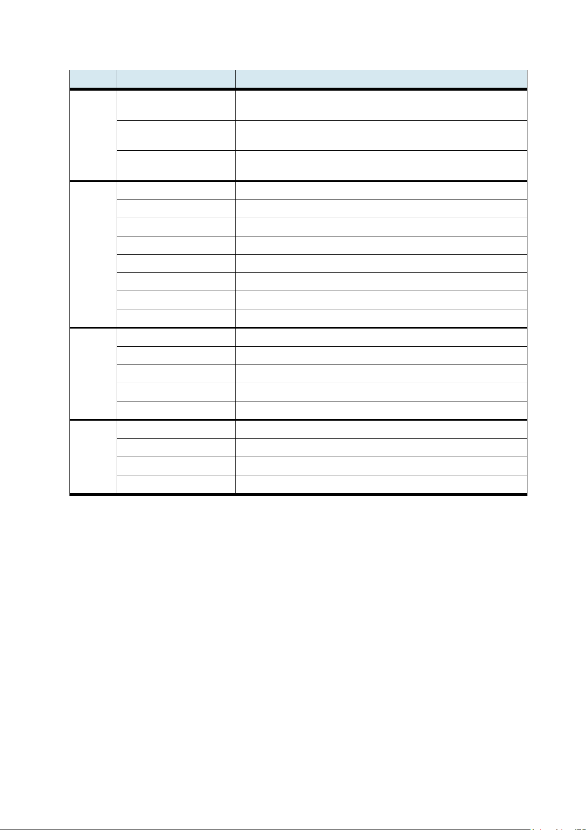
16 Diagnoseanzeige
Die 36 LEDs signalisieren folgende Zustände:
Power
Digitaleingänge
Hallsensoren
RF
ID
Ohne
Funktion
C
A
N
U
S
B
Power I/O
Power 5 V DI7
DI6
DI5
DI4
DI3
DI2
DI1
DI0
-BE2
-BE1
-BG1
RFID- Ready
Status CPU 2
Status CPU 1
CAN TxD
USB TxD
Power
3.3 V
STAT-OUT
DO3
DO2
DO1
DO0
-MB4
-MB3
-MB2
-MB1
-BE4
-BE3
-BG2
RFID- Error
Status
CPU 4
Status CPU 3
CAN RxD
USB RxD
Digitalausgänge
Pneumatikventile
Hallsensoren
RF
ID
Ohne
Funktion
Page 32
CPS-Gate
32 © Festo Didactic 8075265
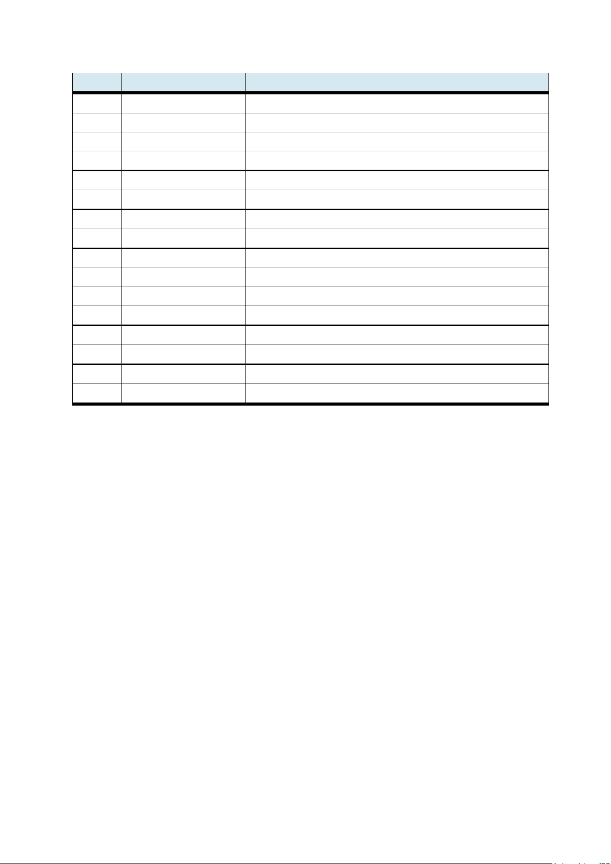
Bezeichnung LED
Diagnose, wenn LED ein…
Power I/O
die +24 VDC Versorgungsspannung für die digital ein-/Ausgänge, Anschluss X8, 1+2,
steht an. Die Versorgungsspannung für die CPU muss anstehen.
Power 5 V
die +24 VDC Versorgungsspannung für die CPU, Anschluss X11, 1+2, steht an. Interner
5 V Regler ok
Power 3.3 V
die +24 VDC Versorgungsspannung für die CPU, Anschluss X11, 1+2, steht an. Interner
3,3 V Regler ok
DI0
Eingang X6, 1 High
DI1
Eingang X6, 4 High
DI2
Eingang X7, 1 High
DI3
Eingang X7, 4 High
DI4
Eingang X9, 1 High
DI5
Eingang X9, 4 High
DI6
Eingang X10, 1 High
DI7
Eingang X10, 4 High
DO0
Ausgang X8,6 geschaltet
DO1
Ausgang X8,4 geschaltet
DO2
Ausgang X11,6 geschaltet
DO3
Ausgang X11,4 geschaltet
STAT-OUT
Ausgang ok, Keine Übertemperatur / Kurzschluss
-MB1
Ventil 1 geschaltet, Stopper auf
-MB2
Ventil 2 geschaltet, Stopper ab
-MB3
Ventil 3 geschaltet
-MB4
Ventil 4 geschaltet
Page 33
CPS-Gate
© Festo Didactic 8075265 33
Bezeichnung LED
Diagnose, wenn LED ein…
-BE1
Sensor -MB1 registriert ein Magnetfeld (Südpol-orientiert)
-BE2
Sensor -MB2 registriert ein Magnetfeld (Südpol-orientiert)
-BE3
Sensor -MB3 registriert ein Magnetfeld (Südpol-orientiert)
-BE4
Sensor -MB4 registriert ein Magnetfeld (Südpol-orientiert)
-BG1
Stopper in unterer Endlage
-BG2
Stopper in oberer Endlage
RFID Ready
Ohne Funktion
RFID Error
Ohne Funktion
Status-CPU 1
Ohne Funktion
Status-CPU 2
Ohne Funktion
Status-CPU 3
Ohne Funktion
Status-CPU 4
Ohne Funktion
CAN-TxD
Daten werden gesendet
CAN-RxD
Daten werden empfangen
USB-TxD
Daten werden gesendet
USB-RxD
Daten werden empfangen
Page 34

CPS-Gate
34 © Festo Didactic 8075265
17 Anschlussdiagramm
Allgemeines Applikationsbeispiel:
18 Software
Auf unserem Serviceportal https://www.cp.community.festo.com stehen unseren Kunden die aktuellsten
Daten zur Verfügung. Die Zugangsdaten erhalten Sie auf Anfrage.
18.1 CODESYS Programmierumgebung
Mit Hilfe der CODESYS-Programmierumgebung lassen sich komfortabel Programmapplikationen für das
CPS-Gate erstellen. CODESYS bietet eine vollständige Programmierung nach IEC 61131-3. Die
Programmieroberfläche kann kostenlose bezogen werden unter www.codesys.org. Die System-
Voraussetzungen sind auf dieser Webseite aufgeführt.
Für die Nutzung der Bibliotheksfunktionen ist mindestens sie Version 3.5, Service Pack 10, zu verwenden.
Die Version wird auch unter der Bezeichnung 3.5.10.x geführt.
Page 35
CPS-Gate
© Festo Didactic 8075265 35
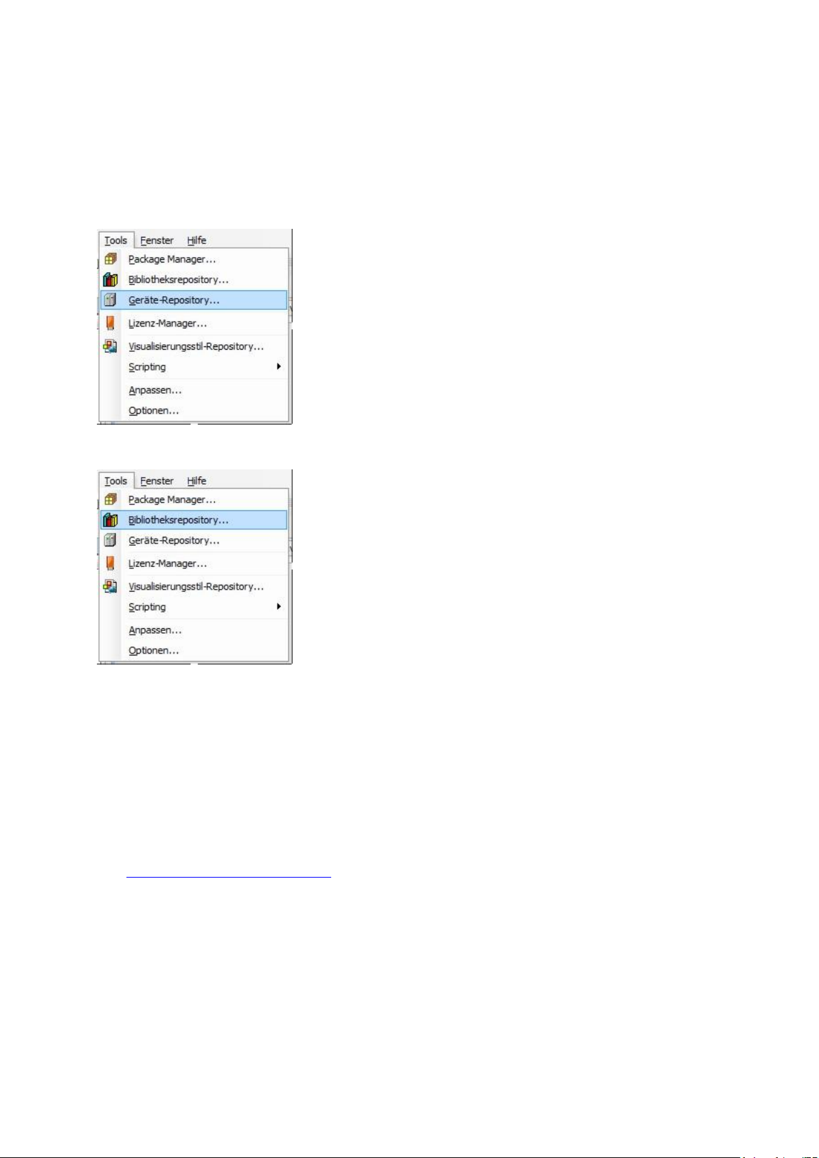
Neben der CODESYS-Programmieroberfläche werden eine Gerätebeschreibungsdatei sowie eine
Bibliotheksdatei benötigt. Beide Dateien können über das Festo Serviceportal bezogen werden.
Die Installation dieser Dateien erfolgt in CODESYS unter dem Reiter „Tools“. Weitere Details zur
Programmierung können der CODESYS Dokumentation entnommen werden.
Installation der Gerätebeschreibungsdatei.
Installation der Bibliotheksdatei
18.2 Web-Visualisierung
Die CODESYS Version auf dem Gerät unterstützt die CODESYS Web-Visualisierung. Diese beruht auf HTML5
und kann somit auf jedem Browser, der die HTML5 Neuerung Canvas unterstützt, ausgeführt werden. Zum
Aufruf der Web-Visualisierung geben Sie in die Adresszeile des Browsers die folgende Adresse ein:
http://<IP Adresse>:<Portnummer>/webvisu.htm
z. B. http://192.168.1.254/webvisu.htm
Im Auslieferungszustand wird für die Web Visualisierung die IP Adresse 192.168.2.254, Port 80 verwendet.
Page 36

CPS-Gate
36 © Festo Didactic 8075265
18.3 IP-Adresse
Im Auslieferungszustand des Gerätes ist die IP-Adresse auf 192.168.2.254 gesetzt.
Diese Adresse kann durch die NFC Schnittstelle und durch die CODESYS Applikation gelesen und geändert
werden.
NFC Memory Map
Byte 3
Byte 2
Byte 1
Byte 0
192
168
002
254
Einstellen der IP-Adresse mit einem NFC fähigen Mobilgerät
• NFC Antenne aktivieren in dem der Betriebsartenschalter S1 auf Mittelstellung (Stopp) gestellt wird.
• Mit einer geeigneten NFC-App können die Adressbytes 0…3 mit den gewünschten IP-Adressteilen
beschrieben werden.
Einstellen der IP-Adresse aus CODESYS
Zum Lesen/Schreiben der IP-Adresse steht die Bibliothek „OPAK_RFID“ zur Verfügung.
Folgendes Codefragment zeigt das Schreiben der IP-Adresse:
// zum Lesen und Schreiben der IP-Adresse durch CODESYS muss die NFC Antenne
// nicht eingeschaltet werden
IF bWriteIP THEN
Address_IP := 16#C0A86479 // 192.168.100.121
NumberOfWiteBytes := ELA_OPAK_RFID.writeToNFC( addr := ELA_OPAK_RFID.IP,
Len := SIZEOF (Address_IP),
Buf := ADR(Address_IP),
Res := ADR(Result)
);
bWriteIP := false;
END_IF
Page 37
CPS-Gate
© Festo Didactic 8075265 37
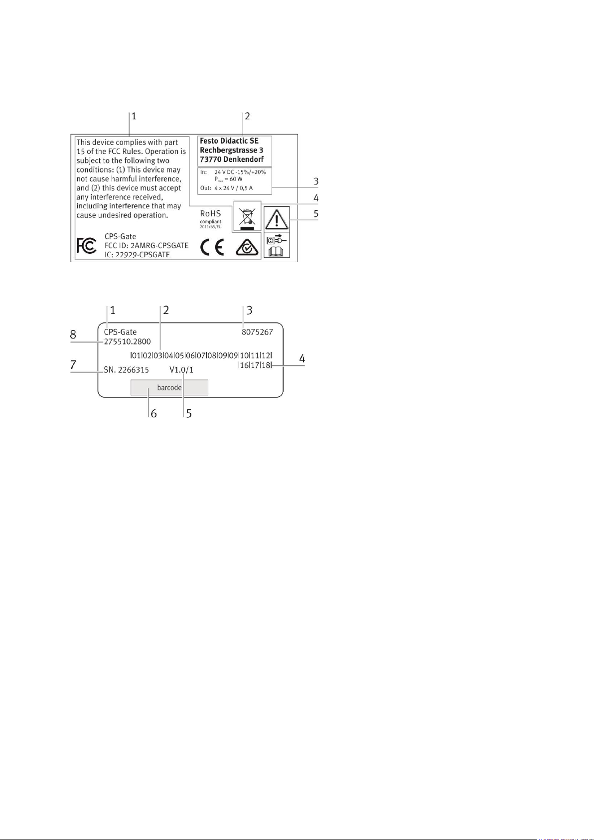
19 Produktkennzeichnung
1 Produktzulassungen
2 Herstelleradresse
3 Technische Daten
4 Entsorgungshinweis
5 Sicherheits- / Warnhinweise
1 Produktbezeichnung
2 Fertigungsmonat
3 Teilenummer (Bestellnummer)
4 Fertigungsjahr
5 Version Vx.x/y
x.x = Hardwareversion,
y = Firmwareversion
6 Barcode
7 Seriennummer
8 interne Identifikationsnummer
20 Wartung und Reinigung
Das Gerät ist wartungsfrei. Zur Reinigung verwenden Sie ein leicht feuchtes, fusselfreies Reinigungstuch
ohne scheuernde, chemische oder lösungsmittelhaltige Reinigungsmittel
21 Lagerung und Transport
Das Gerät wird mit dem Lieferzubehör in der Herstellerverpackung geliefert. Die bietet ausreichend Schutz
für das Gerät bei Transport und Lagerung. Die Lagerbedingungen sind in den technischen Daten aufgeführt.
Page 38

CPS-Gate
38 © Festo Didactic 8075265
22 Lieferumfang
• CPS-Gate
• Schutzabdeckungen für elektrische Anschlussbuchsen
• Benutzerhandbuch
• Montagematerial
• Steckverbindung QSM, reduzierend, 4 mm --> 3 mm, QSM-4-3, Festo AG & Co. KG
Bestellnummer 153326
• 300 mm Pneumatik-Kunststoffschläuche, PUN-3x0,5-SI
23 Zubehör, Ersatzteile
• Festo Didactic Tischnetzteil SELV/PELV mit Energiebegrenzung, Festo Didactic Bestellnummer 8049633
• Pneumatik-Kunststoffschläuche, silber, 50 m: PUN-3x0,5-SI
• Ersatzfederleisten für -X6 … -X11: Federleiste mit Griffplatte; Kabelbündelungsfunktion und
Entriegelungshilfe;
6-polig; Rastermaß 3,5 mm
Wago Bestellnummer 2091-1106/002-000
• RFID-Tag, ISO 15693, Turck, Typ: TW-R16-B128, Turck-Bestellnummer 6900501
24 Entsorgung
Elektronische Altgeräte sind Wertstoffe und gehören nicht in den Hausmüll. Die Entsorgung
erfolgt über die kommunalen Sammelstellen.
25 CE Konformitätserklärung
Vereinfachte EU-Konformitätserklärung nach Artikel 10, Absatz 9 der Richtlinie 2014/53/EU:
Hiermit erklärt Festo Didactic SE, dass der Funkanlagentyp CPS-Gate, Bestellnummer 8075267,
der Richtlinie 2014/53/EU entspricht.
Der vollständige Text der EU-Konformitätserklärung ist unter der folgenden Internetadresse verfügbar:
http://www.festo-didactic.com/de-de/service/printmedien/zertifikate-produktkonformitaet
Page 39

CPS Gate
© Festo Didactic 8075265 39
Table of contents
1 General prerequisites for operating the devices _________________________________________ 41
2 Pictograms ______________________________________________________________________ 42
3 Use for intended purpose ___________________________________________________________ 43
4 For your safety ___________________________________________________________________ 44
4.1 Important notes __________________________________________________________________ 44
4.2 Obligations of the operating company ________________________________________________ 44
4.3 Obligations of apprentices __________________________________________________________ 44
5 Work and safety instructions ________________________________________________________ 45
6 Version information _______________________________________________________________ 47
7 Technical data ____________________________________________________________________ 48
8 Approvals/standards ______________________________________________________________ 50
9 Description ______________________________________________________________________ 52
10 Connections, display, and operating components _______________________________________ 53
10.1 Rear view ________________________________________________________________________ 53
10.2 Front view _______________________________________________________________________ 53
10.3 Top view ________________________________________________________________________ 54
10.4 Side view ________________________________________________________________________ 54
11 Installation ______________________________________________________________________ 55
11.1 Mounting ________________________________________________________________________ 55
11.2 Dismounting _____________________________________________________________________ 56
11.3 Electrical connection_______________________________________________________________ 56
11.3.1 USB Port ________________________________________________________________________ 57
11.3.2 CAN interface ____________________________________________________________________ 58
11.3.3 Ethernet interfaces ________________________________________________________________ 59
11.3.4 Digital inputs _____________________________________________________________________ 60
11.3.5 Digital outputs, power supply _______________________________________________________ 61
Page 40

CPS Gate
40 © Festo Didactic 8075265
12 Magnetic field sensors _____________________________________________________________ 62
13 RFID ____________________________________________________________________________ 62
14 NFC ____________________________________________________________________________ 63
15 Mode selector ____________________________________________________________________ 63
16 Diagnostic display ________________________________________________________________ 66
17 Wiring diagram ___________________________________________________________________ 69
18 Software ________________________________________________________________________ 69
18.1 CODESYS programming environment _________________________________________________ 69
18.2 Web visualization _________________________________________________________________ 70
18.3 IP address _______________________________________________________________________ 71
19 Product labeling __________________________________________________________________ 72
20 Maintenance and cleaning __________________________________________________________ 72
21 Storage and transport _____________________________________________________________ 72
22 Scope of delivery _________________________________________________________________ 73
23 Accessories and spare parts ________________________________________________________ 73
24 Disposal ________________________________________________________________________ 73
25 CE declaration of conformity ________________________________________________________ 73
Page 41

CPS Gate
© Festo Didactic 8075265 41
1 General prerequisites for operating the devices
General requirements for safe operation of the devices:
• National regulations for operating electrical systems and equipment must be observed in commercial
facilities.
• The laboratory or classroom must be overseen by a supervisor.
– A supervisor is a qualified electrician or a person who has been trained in electrical engineering,
knows the respective safety requirements and safety regulations, and whose training has been
documented accordingly.
The laboratory or the classroom must be equipped with the following devices:
• An emergency-off device must be provided.
– At least one emergency-off device must be located within, and one outside of, the laboratory or the
classroom.
• The laboratory or classroom must be secured so that operating voltage and compressed air supply
cannot be activated by any unauthorized persons, for example by means of:
– Key switches
– Lockable shut-off valves
• The laboratory or classroom must be protected by residual current devices (RCDs).
– Electrical devices (e.g. power supply units, compressors and hydraulic units) may only be operated
in training rooms which are equipped with residual current devices.
– Type B residual current circuit breakers with a residual current of ≤ 30 mA must be used.
• The laboratory or classroom must be protected by overcurrent protection devices.
– Fuses or circuit breakers
• No damaged or defective devices may be used.
– Damaged devices must be barred from further use and removed from the laboratory or classroom.
– Damaged connecting cables, pneumatic tubing and hydraulic hoses represent a safety risk and
must be removed from the laboratory or classroom.
Page 42
CPS Gate
42 © Festo Didactic 8075265
2 Pictograms
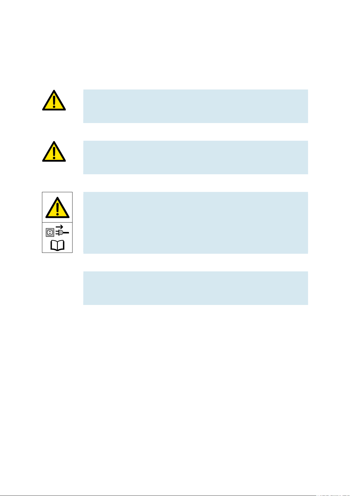
This document and the hardware described herein include warnings about possible dangers which may
occur if the system is used incorrectly. The following pictograms are used:
Warning
This pictogram indicates that non-observance may result in serious personal injury
or damage to property.
Caution
This pictogram indicates that non-observance may result in personal injury or
damage to property.
Warning
This pictogram indicates that the device must be switched off and its mains plug
must be removed from the electrical outlet before installation, repair, maintenance
and cleaning work. Observe the user documentation, in particular all safety
instructions. Non-observance may result in severe personal injury or damage to
property.
Note
This pictogram indicates that instructions for use for intended purpose must be
complied with. Non-compliance may result in functional restrictions.
Page 43

CPS Gate
© Festo Didactic 8075265 43
3 Use for intended purpose
The CPS Gate from Festo Didactic may only be used:
• For its intended use in teaching and training applications
• When its safety functions are in perfect condition
The CPS Gate is designed in accordance with the latest technology and recognized safety rules. However,
life and limb of the user or third parties may be endangered and the components may be impaired if it’s
used incorrectly.
The learning system from Festo Didactic has been developed and produced exclusively for basic and further
training in the field of automation technology. The training company and/or trainers must ensure that all
apprentices observe the safety precautions described in this document.
Festo Didactic hereby excludes any and all liability for damages suffered by apprentices, the training
company and/or any third parties, which occur during use of the equipment sets in situations that serve any
purpose other than training and/or vocational education, unless such damages have been caused by Festo
Didactic due to malicious intent or gross negligence.
The CPS Gate controller documented in these operating instructions is intended exclusively for installation
into Festo Didactic’s conveyor.
Page 44

CPS Gate
44 © Festo Didactic 8075265
4 For your safety
4.1 Important notes
Fundamental prerequisites for safe use and trouble-free operation of the CPS Gate include knowledge of
basic safety precautions and safety regulations. These operating instructions include the most important
instructions for safe use of the device.
In particular the safety instructions must be adhered to by all persons who work with the CPS gate. In
addition, all pertinent accident prevention rules and regulations which are applicable at the respective place
of use must be adhered to.
4.2 Obligations of the operating company
The operating company undertakes to allow only those persons to work with the device who:
• Are familiar with the basic regulations regarding work safety and accident prevention and have been
instructed in the use of the device
• Have read and understood the safety chapter and warnings in these operating instructions
Personnel should be tested at regular intervals for safety-conscious work habits.
4.3 Obligations of apprentices
All persons who have been entrusted to work with the device undertake to complete the following steps
before beginning work:
• Read the chapter concerning safety and the warnings in these operating instructions
• Familiarize themselves with the basic regulations regarding occupational safety and accident
prevention.
Warning
All of the safety devices of the machine which is connected to the CPS Gate must be
functional.
The electrical safety of the machine must be verifiably assured.
Page 45

CPS Gate
© Festo Didactic 8075265 45
5 Work and safety instructions
General
• Apprentices should only work with the circuits under the supervision of an instructor.
• Observe the specifications included in the technical data for the individual components, and in
particular all safety instructions!
• Malfunctions which may impair safety must not be generated.
• Wear personal safety equipment (safety glasses, safety shoes) when working on circuits.
Electrical safety
• Risk of death in case of interrupted protective earth conductor!
– The protective earth conductor (yellow-green) must not be interrupted, either inside or outside of
the device.
– The insulation of the protective conductor must never be damaged or removed.
• Risk of death from connecting power supply units in series!
Contact voltages of greater than 25 V ac or 60 V dc are not permissible.
Coming into contact with voltages of greater than 50 V ac or 120 V dc may be fatal.
– Do not connect voltage sources in series.
• Risk of death due to electric shock!
Protect the outputs of the power supply units (output sockets/terminals) and cables connected to them
from direct contact.
– Use only cables with adequate insulation and electric strength.
– Use safety sockets with fully shrouded contact points.
• Disconnect from all sources of electrical power!
– Switch off the power supply before working on the circuit.
– Please note that electrical energy may be stored in individual components. Further information on
this issue is available in the data sheets and operating instructions included with the components.
– Caution!
Capacitors inside the device may still be charged even after being disconnected from all sources of
voltage.
• Establishing and interrupting electrical connections
– Electrical connections may only be established in the absence of voltage.
– Electrical connections may only be interrupted in the absence of voltage.
Page 46

CPS Gate
46 © Festo Didactic 8075265
• Maximum permissible current loads for cables and devices must not be exceeded.
– Always compare the current ratings of the device, the cable and the fuse.
– If these are not the same, use a separate upstream fuse in order to provide appropriate overcurrent
protection.
• Use only connecting cables with safety plugs for electrical connections.
• When laying connecting cables, make sure they’re not kinked or pinched.
• Do not lay cables over hot surfaces.
– Hot surfaces are identified with a corresponding warning symbol.
• Make sure that connecting cables are not subjected to continuous tensile loads.
• The device is not equipped with an integrated fuse unless otherwise specified in the technical data.
• Always pull on the safety plug when disconnecting cables – never pull the cable.
• In the event of
– visible damage,
– malfunction,
– inappropriate storage or
– incorrect transport,
safe operation of the device is no longer possible.
– Switch off the power supply immediately.
– Protect the device against inadvertent restart.
Pneumatic safety
• Depressurize the system.
– Switch off the compressed air supply before working on the circuit.
– Check the system with pressure gauges to make sure that the entire circuit is fully depressurized.
– Please note that energy may be stored in reservoirs. Further information on this issue is available in
the data sheets and operating instructions included with the components.
• Do not exceed the maximum permissible pressure of 600 kPa (6 bar).
• Do not switch on compressed air until all tubing connections have been established and secured.
• Do not disconnect tubing while under pressure.
• Risk of injury when switching compressed air on!
Cylinders may advance and retract automatically.
• Risk of accident due to advancing cylinders.
– Always position pneumatic cylinders so that the piston rod’s working space is unobstructed over
the entire stroke range.
– Make sure that the piston rod cannot collide with any rigid components of the setup.
• Risk of accident due to tubing slipping off.
– Use shortest possible tubing connections.
– In the event that tubing slips off: switch compressed air supply off immediately.
Page 47
CPS Gate
© Festo Didactic 8075265 47
• Switch compressed air supply off before dismantling the circuit.
• Noise due to escaping compressed air!
– Noise caused by escaping compressed air may damage your hearing. Reduce noise by using
silencers, or wear hearing protection if noise can’t be avoided.
– All of the exhaust ports of the components included in the equipment set are equipped with
silencers. Do not remove these silencers.
Caution!
Improper repairs or modifications may result in unforeseeable operating states. Do
not carry out repairs on the device.
6 Version information
This description refers to the following versions:
– Festo CPS Gate controller version 1.0/0
– CODESYS V3 software package provided by Festo (pbF)
The description contains information concerning the function of the CPS Gate, as well as its mounting,
installation and commissioning.
Version
Description
V1.0/0
Approved initial series
Page 48
CPS Gate
48 © Festo Didactic 8075265
7 Technical data
Technical data
CPU
Processor
Single-core Cortex A9, 800 MHZ
Real-time clock
Included, buffered for up to 4 weeks by means of Gold-Cap
Memory
4 GByte RAM, 1 GByte flash
Buffering
1 MByte data retention in flash memory
Software/functionality
Operating system
Embedded Linux 4.00
PLC programming
CODESYS V3 (CS3)
HMI programming
CODESYS V3 WebVisu (WV)
Ethernet TCP Modbus client or server
Can be implemented via IEC library
EtherCAT master (optional)
Integrated into CODESYS V3 (CS3)
CANopen master
Can be implemented via IEC library
OPC UA (optional)
Integrated into CODESYS V3 (CS3)
Electrical interfaces
X1
USB diagnostics (type B USB device socket)
X2
CAN in accordance with ISO11898 with electrical isolation, RJ45
X3 … X5
Ethernet interfaces, 100BASE-T, RJ45 with triple switch functionality
X6
Digital inputs DI0, DI1
Input voltage
Max. frequency
Input delay
Overvoltage
Power loss
Min. high voltage
Max. low voltage
24 V dc, EN 61131-2 type 1
100 Hz
≤ 10 ms
33 V
0.2 W per input
24 mA supply current per input
15 V
5 V
X7
Digital inputs DI2, DI3
X9
Digital inputs DI4, DI5
X10
Digital inputs DI6, DI7
X8
Digital outputs DO0, DO1,
power supply,
digital inputs/outputs
Output voltage
Output current
Total current
(per DIN)
Resistive load
Switching frequency,
ohmic/inductive
Short-circuit/thermal
protection,
current limiting,
fuse,
power loss
24 V dc, EN 61131-2 type 1
0.5 A
Max. 2 A ( at 50% duty cycle)
48 W nominal
100 Hz
0.7 per channel,
2 A for total current
0.2 W per output
X11
Digital outputs DO2, DO3,
CPU power supply
Page 49

CPS Gate
© Festo Didactic 8075265 49
Technical data (continued)
Wireless interfaces
NFC for configuration
4 kBit EEPROM, ISO 15693
RFID for logistics functions
13.56 MHz reader/writer, multi-protocol with integrated antenna
RFID transmission power
49.83 dBµV/m at 3 m (45.4 dBm ±2 dBm)
Internal sensors/actuators
Hall sensors
4 magnetic field sensors for detecting the workpiece carrier
2 sensors for detecting the position of the stopper
Stopper
Pneumatic stopper applicator, 3 mm supply port, max. 600 kPa (6 bar)
Operation and display components
S1
Mode selector for PLC
Status LEDs
36 LEDs for operating and status signals
Mechanical data
Outside dimensions (W x H x D)
120 x 144 x 30 mm
Weight
Approx. 660 g
Housing
Aluminum housing with plastic cover
Degree of protection
IP20 in accordance with EN 60529
Mounting
40 mm extruded aluminum profile –
the device must be thermally and electrically connected to the structure of the machine.
Operating conditions
Operating temperature
5 … 40° C
Storage temperature
-20 … 70° C
Relative humidity, operation
10% … 5%, non-condensing
Relative humidity, storage
5% … 85%, non-condensing
Cooling
Passive heatsink, convection must be provided for
Device operation
For indoor use only up to 3000 m above sea level
Electrical connection data
Supply voltage
24 V dc (20.4 – 28.8 V), protected against polarity reversal
Supply only with SELV/PELV power pack including energy limiting,
backup fuse: max. 4 AT
Power consumption
Max. 60 W
Power consumption, valves
4 x 1 W (4 x 40 mA)
Current consumption, CPU
240 mA
Current consumption, digital outputs
4 x 500 mA
Page 50

CPS Gate
50 © Festo Didactic 8075265
8 Approvals/standards
Certifications
CE marking per
Radio Equipment Device (RED) Directive
Spectrum: ETSI EN 300330
Safety EN 61131-2
EMC ETSI EN 300489-1, ETSI EN 301489-3
EN 61131-2
RoHS directive
EN 50581
RCM
Marketing approval, Australia
FCC
FCC ID: 2AMRG-CPSGATE
IC
IC: 22929-CPSGATE
For use in USA
FCC Statement in accordance with CFR 47, subpart 15.19
This device complies with part 15 of the FCC rules. Operation is subject to the following two conditions:
1. this device may not cause harmful interference, and
2. this device must accept any interference received, including interference that may cause undesired
operation.
No changes shall be made to the equipment without the manufacturer’s permission as this may void the
user’s authority to operate the equipment.
FCC RF Exposure Statement:
This equipment complies with FCC radiation exposure limits set forth for an uncontrolled environment. End
users must follow the specific operating instructions for satisfying RF exposure compliance.
This equipment shall be installed and operated with a minimum distance of 1 cm between the user and this
device.
For use in Canada
In accordance with RSS-Gen, section 8.4, all license-exempt radio devices shall state the following:
This device complies with ISED’s license-exempt RSSs. Operation is subject to the following two conditions:
1. This device may not cause interference; and
1. This device must accept any interference, including interference that may cause undesired operation of
the device
Le présent appareil est conforme aux CNR d’Industrie Canada applicables aux appareils radio exempts de
licence. L’exploitation est autorisée aux deux conditions suivantes :
1. l’appareil ne doit pas produire de brouillage ;
2. l’utilisateur de l’appareil doit accepter tout brouillage radioélectrique subi, même si le brouillage est
susceptible d’en compromettre le fonctionnement.
Page 51

CPS Gate
© Festo Didactic 8075265 51
RF Exposure Statement:
The equipment conforms to the RF Exposure Evaluation Limits laid down in RSS 102.
Déclaration d‘exposition RF:
L‘équipement est conforme aux valeurs limites d‘évaluation de l‘exposition aux radiofréquences selon CNR
102.
Page 52

CPS Gate
52 © Festo Didactic 8075265
9 Description
The CPS Gate is a multifunctional controller with PLC functionality. The CODESYS programming environment
with comprehensive library functions runs on a high-performance processor core.
Numerous modern industrial and media interfaces make use possible in an Industry 4.0 environment. The
controller, the sensors, the actuators, and the communication interfaces are combined in the CPS Gate and
are located directly at the field application.
The device can be configured for the application via the wireless NFC interface using a mobile device. The
RFID interface permits continuous reading/writing of information from/to the workpiece carrier.
Furthermore, workpiece carriers can be coded with magnets which are detected by 4 integrated magnetic
field sensors. The pneumatic stopper can stop the workpiece carriers and release them for further transport.
The position of the stopper’s piston rod is detected by 2 further sensors.
Block diagram of the CPS Gate
Page 53
CPS Gate
© Festo Didactic 8075265 53
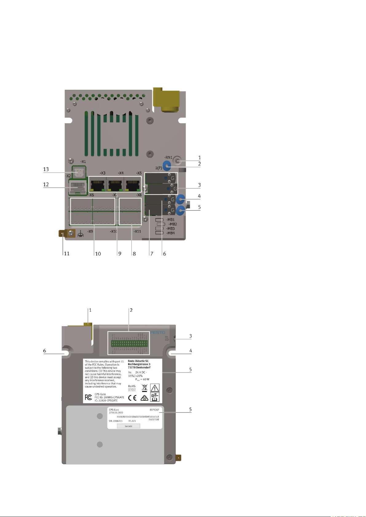
10 Connections, display, and operating components
10.1 Rear view
1
Exhaust air flow control for valves 1 and
2
2
Supply port for valves 1 … 4
3
Solenoid coils -MB1 and -MB2 for
internal stopper
4
Working port of valve 3
5
Working port of valve 4
6
Solenoid coil -MB3
7
Solenoid coil -MB4
8
Connection terminals -X8 and -X11 for
digital outputs and supply voltage
9
Connection terminals -X3 … -X4 for
Ethernet
10
Connection terminals -X6, -X7, -X9
and -X10 for digital inputs
11
Functional earth terminal
12
CAN terminal -X2
13
USB port -X1
10.2 Front view
1
Stopper
2
Diagnostic display
3
Mode selector
4
Mounting hole
5
Rating plate
6
Mounting hole
Page 54
CPS Gate
54 © Festo Didactic 8075265
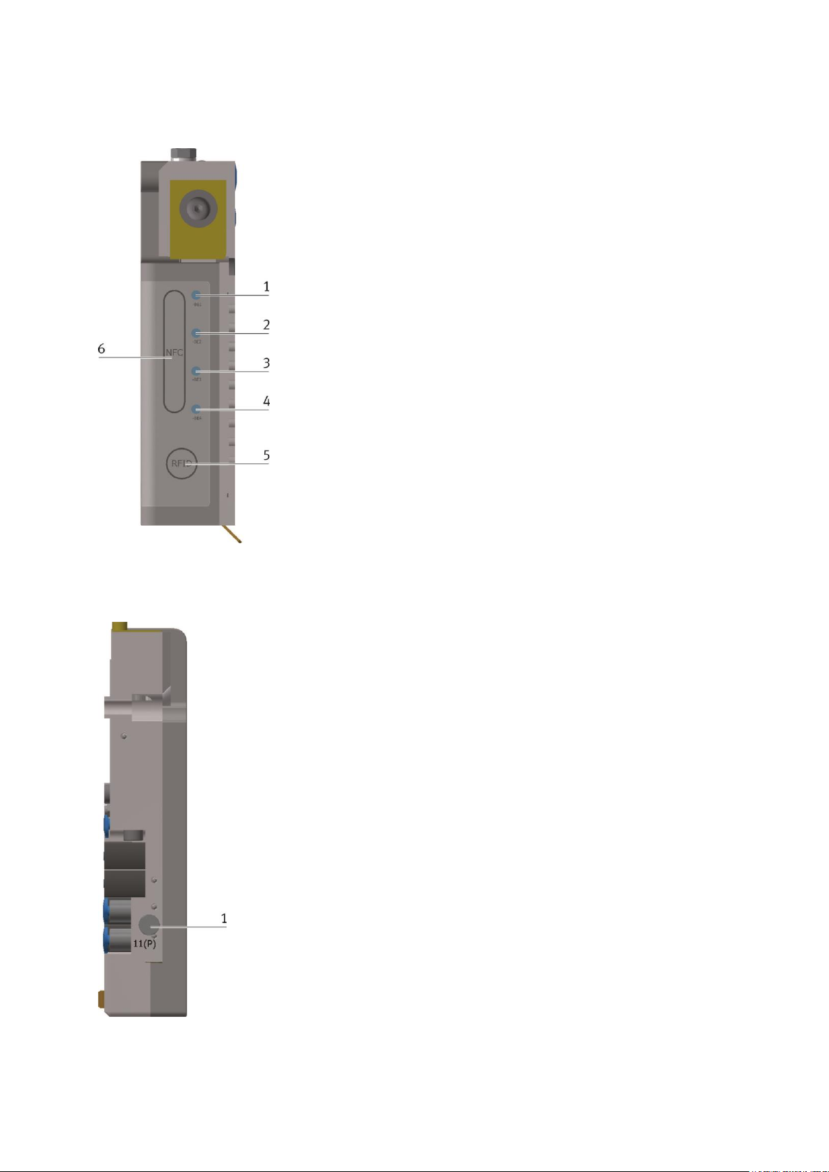
10.3 Top view
1
Magnetic field sensor position, -BE1
2
Magnetic field sensor position, -BE2
3
Magnetic field sensor position, -BE3
4
Magnetic field sensor position, -BE4
5
RFID antenna
6
NFC antenna
10.4 Side view
1
Alternative supply port 11 (P)
Page 55

CPS Gate
© Festo Didactic 8075265 55
11 Installation
Warning
The device may not be used to control safety-relevant equipment. Functional safety
cannot be assured!
Caution
The operating instructions must be read before installation and commissioning, and
carefully followed. Applicable safety regulations must be complied with.
Allow the module to adjust to room temperature before commissioning. In the event of
condensation, the device may not be switched on until it’s absolutely dry.
In order to prevent overheating of the device during operation,
– it must not be exposed to direct sunlight,
– the ventilation slots in the housing may not be covered as a result of installation,
– adequate air circulation must be ensured.
11.1 Mounting
The device is screwed on to the conveyor belt’s rectangular aluminum profile. The mounting components are
included. The device may only be installed vertically, so that the stopper cylinder executes vertical motion. It
is important to ensure that surface of the device’s aluminum body makes good contact with the profile.
The electrical connections are located on the back of the device. They have to be accessible after mounting.
The device is secured to the 40 mm aluminum
profile at mounting holes 1 and 2.
Two DIN 912 M5x20 mm screws are included
for this purpose.
The slot nuts must be inserted at the
corresponding points in the aluminum profile.
Page 56

CPS Gate
56 © Festo Didactic 8075265
It must be assured that the protruding lip (3)
extends into the aluminum profile’s
longitudinal slot.
11.2 Dismounting
The device may only be dismounted in the voltage-free state. All ancillary equipment which is connected to
the CPS Gate must be voltage-free.
All of the device’s electrical connections are interrupted. The device is then unscrewed. In the event that the
device is discarded, it must be disposed of properly at a community collection point or by returning it to the
manufacturer.
If the device will be used again later, all of the electrical terminals must be sealed with the corresponding
cover caps.
11.3 Electrical connection
All of the required electrical connections are established in the voltage-free state. Unused terminals are
closed with the corresponding cover caps.
All of the electrical signals must be connected to a receiving point before commissioning.
Caution
The device is equipped with a functional earth terminal (FE) which must be permanently
connected, via low resistance, to the protective conductor system of the electrical
installation before commissioning.
Note
Highly flexible braided copper straps are suitable for the FE connection. Solid wire is not
recommended.
Page 57

CPS Gate
© Festo Didactic 8075265 57
Caution
The device may only be supplied with electrical power from a SELV/PELV power pack
with energy limiting. The maximum backup fuse is 4 AT.
Note
In order to avoid interference injection, the length of the dc supply cable may not
exceed 3 m.
All connecting cables should be laid separately from interference conducting lines
(power current, motor cables) in order to avoid interference injection.
Note
Integrated antennas for RFID and NFC communication are located on the top of the
device. These must not be covered.
11.3.1 USB Port
USB, -X1
Pin
Assignment
Function
1
+5 V (max. 500 mA)
Supply voltage
2
Data-
3 Data+
4 GND 5 V (signal ground)
Supply voltage
The USB port must be supplied with operating voltage (5 V dc) from the communication interface, in order
to make communication possible.
In the event of communication interference, electrical isolation between the USB port and the external USB
device is recommended, in order to interrupt the ground loop. An appropriate USB hub can be used to end.
Page 58
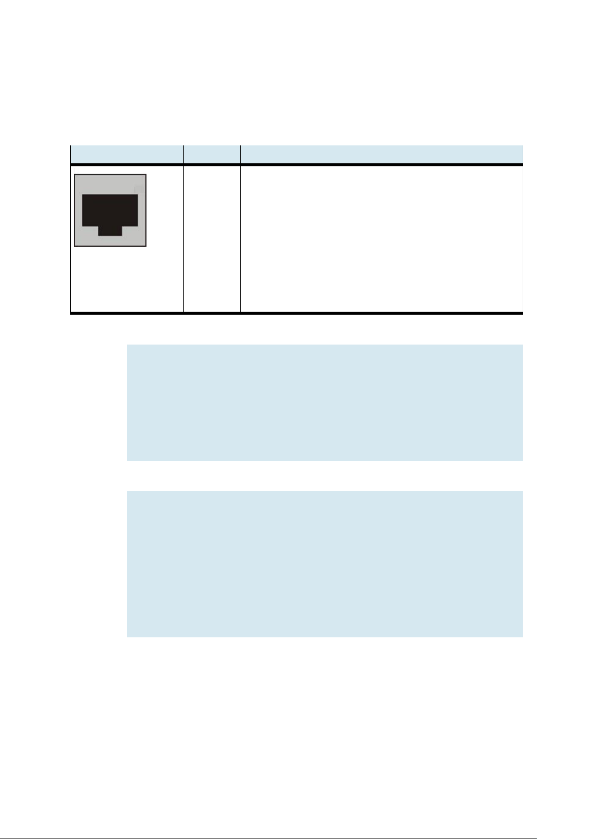
CPS Gate
58 © Festo Didactic 8075265
11.3.2 CAN interface
This interface is implemented by means of an 8-pin RJ45 plug. It’s electrically isolated from the device’s
supply voltage.
CAN, -X2
Pin
Assignment
1
2
3
4
5
6
7
8
Shld
CAN-H
CAN-L
GND (signal ground for CAN) HF coupling to FE (1 MΩ || 22 nF)
NC
NC
NC
NC
NC
Shield, HF coupling to FE (1 MΩ || 22 nF)
Notes
– Unconnected pins 4 … 8 may not be used by the remote partner.
– Based on the overall bus structure, check to determine whether or not an
external terminating resistor is required. As a rule, these terminating resistors
are located at the beginning and the end of the bus cable.
Resistance is typically 120 Ω.
– Use a twisted 2-wire cable with shield for the CANopen bus.
Note
Faulty installation and high transmission rates may cause data transmission errors as
a result of signal reflections and signal attenuation. Transmission errors can be
caused by:
– Missing terminating resistor between CAN_L (pin 2) and CAN_H (pin 1)
– Faulty shield connection
– Branches
– Large distances
– Unsuitable cables
Page 59
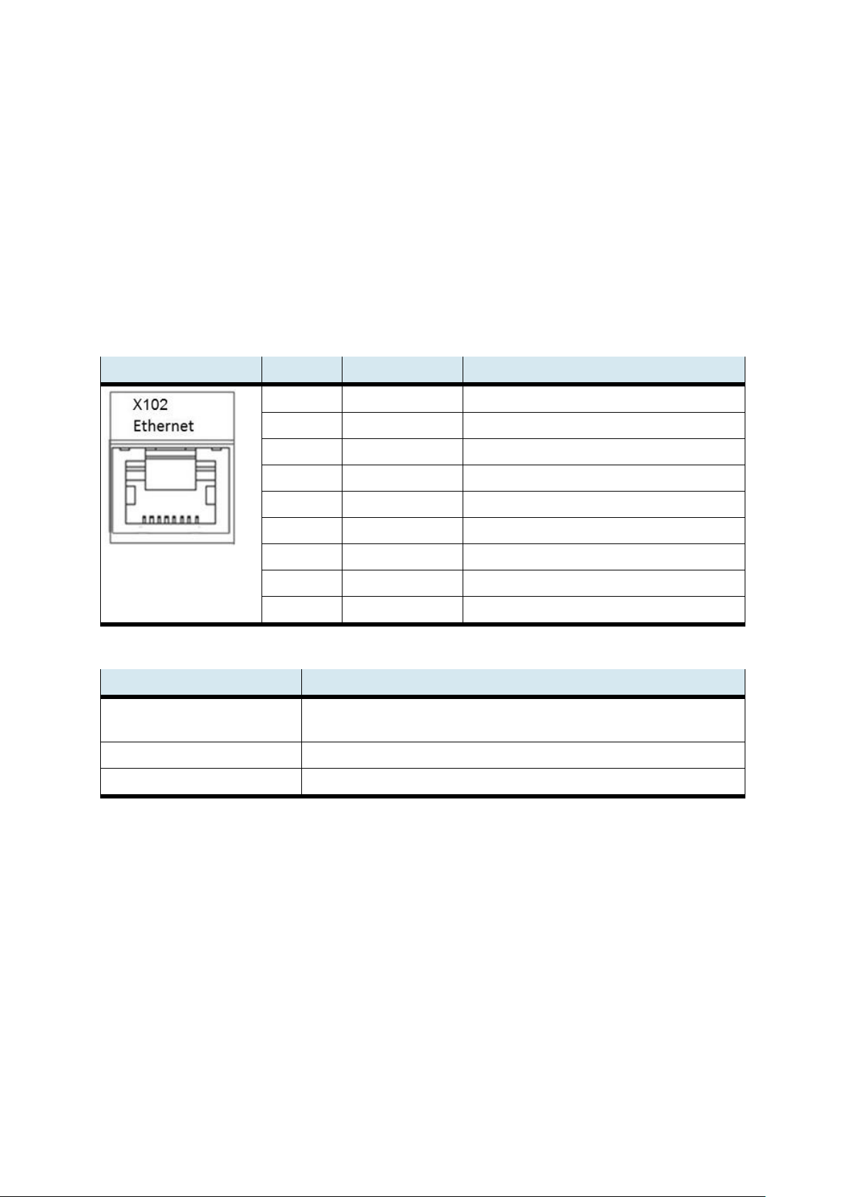
CPS Gate
© Festo Didactic 8075265 59
11.3.3 Ethernet interfaces
The Ethernet interfaces are laid out as RJ45 sockets with switch functionality.
The integrated 10/100 MBit Ethernet switch supports Auto-MDI(X). Crossover as well as patch cables can be
used.
Connections and cables are in accordance with CAT 5. The Ethernet connection must be grounded at the
remote partner.
The functional earth terminal of the CPS Gate must be grounded.
Interfaces -X3, -X4 and -X5
Pin
Assignment
Function
1
TX+
Transmit data +
2
TX-
Transmit data -
3
RX+
Receive data +
4
n.c.
None 5 n.c.
None 6 RX-
Receive data -
7
n.c.
None 8 n.c.
None
Shld
Shield housing
Connected to FE
Ethernet
3x RJ45 (switched)
Transmission medium
At least twisted-pair SF-UTP, 100 Ω, CAT 5,
max. 100 m cable length
Transmission rate
10/100 Mbit/s
Protocols
DHCP, DNS, FTP, HTTP, HTTPS, SSH
Page 60
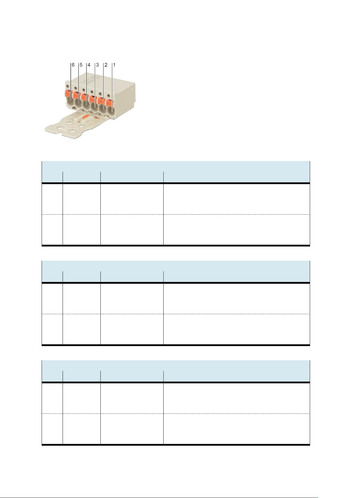
CPS Gate
60 © Festo Didactic 8075265
11.3.4 Digital inputs
Connector pins for interfaces -X6 … -X11
Manufacturer: Wago,
Order number: 2091-1106/002-000
-X6, digital inputs DI0, DI1
Pin
Designation
Function
Note
1
2
3
DI0
GND
+24 V
Digital input 0
Reference ground
Supply voltage
Electrically isolated
Connected to -X8, 1+3
Connected to -X8, 2, for sensor supply
4
5
6
DI1
GND
+24 V
Digital input 1
Reference ground
Supply voltage
Electrically isolated
Connected to -X8, 1+3
Connected to -X8, 2, for sensor supply
-X7 digital inputs DI2, DI3
Pin
Designation
Function
Note
1
2
3
DI2
GND
+24 V
Digital input 2
Reference ground
Supply voltage
Electrically isolated
Connected to -X8, 1+3
Connected to -X8, 2, for sensor supply
4
5
6
DI3
GND
+24 V
Digital input 3
Reference ground
Supply voltage
Electrically isolated
Connected to -X8, 1+3
Connected to -X8, 2, for sensor supply
-X9, digital inputs DI4, DI5
Pin
Designation
Function
Note
1
2
3
DI4
GND
+24 V
Digital input 4
Reference ground
Supply voltage
Electrically isolated
Connected to -X8, 1+3
Connected to -X8, 2, for sensor supply
4
5
6
DI5
GND
+24 V
Digital input 5
Reference ground
Supply voltage
Electrically isolated
Connected to -X8, 1+3
Connected to -X8, 2, for sensor supply
Page 61
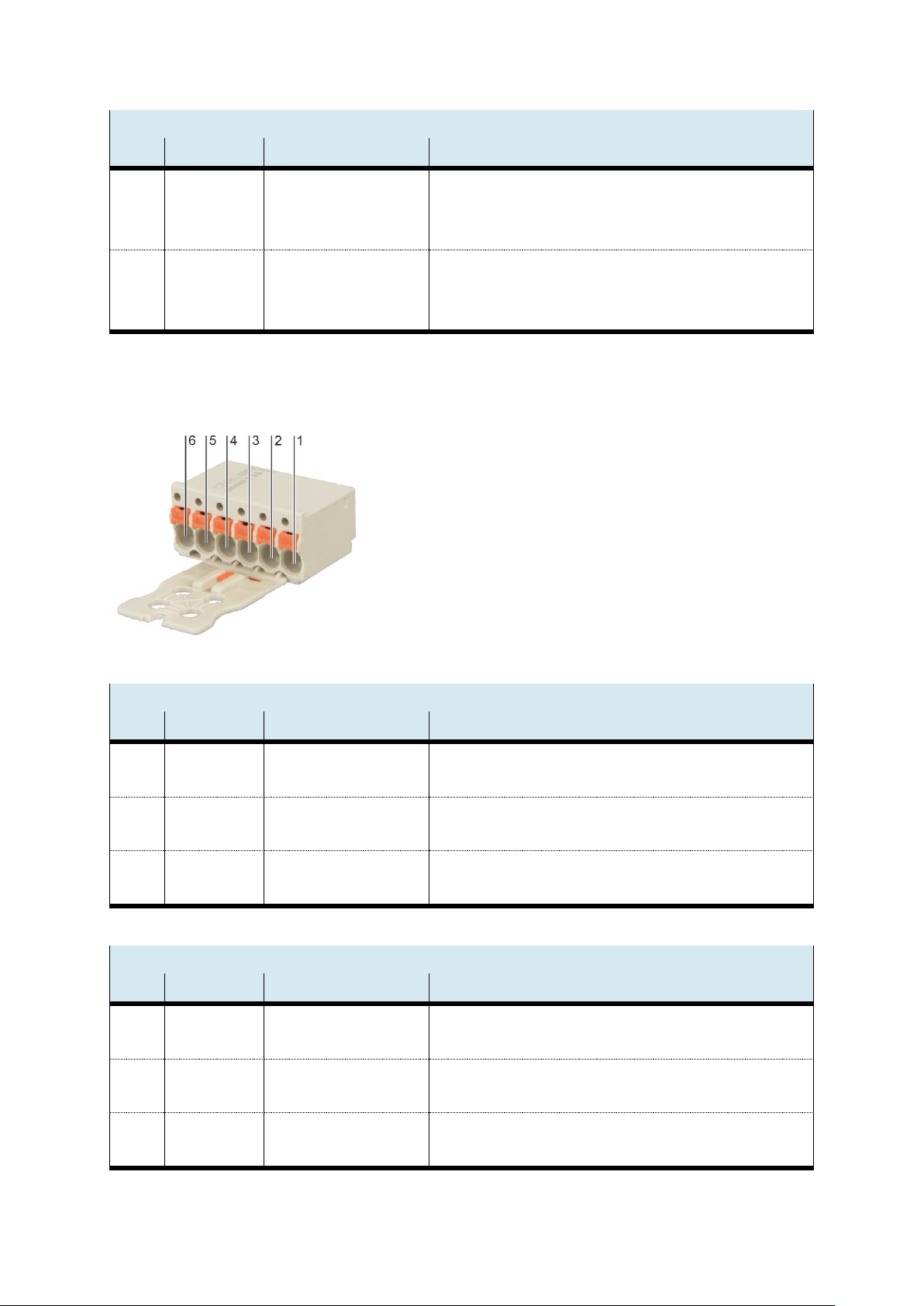
CPS Gate
© Festo Didactic 8075265 61
-X10, digital inputs DI6, DI7
Pin
Designation
Function
Note
1
2
3
DI6
GND
+24 V
Digital input 6
Reference ground
Supply voltage
Electrically isolated
Connected to -X8, 1+3
Connected to -X8, 2, for sensor supply
4
5
6
DI7
GND
+24 V
Digital input 7
Reference ground
Supply voltage
Electrically isolated
Connected to -X8, 1+3
Connected to -X8, 2, for sensor supply
11.3.5 Digital outputs, power supply
Connector pins for interface -X8, -X11
Type: Wago-2091-1406
-X8, digital outputs DO0, DO1, supply voltage, digital interfaces
Pin
Designation
Function
Note
1 2 GND
+24 V
Reference ground
Supply voltage
GND supply terminal for digital interfaces
+24 V supply terminal for digital interfaces
3 4 GND
DO1
Reference ground
Digital output 1
Connected to -X8, 1, reference potential for DO1
Electrically isolated from CPU supply voltage
5 6 GND
DO0
Reference ground
Digital output 0
Connected to -X8, 1, reference potential for DO0
Electrically isolated from CPU supply voltage
-X11, digital outputs DO2, DO3, CPU supply voltage
Pin
Designation
Function
Note 1 2
GND_CPU
+24V_CPU
Reference ground
Supply voltage
GND supply terminal for CPU
+24 V supply terminal for CPU
3 4 GND
DO3
Reference ground
Digital output 3
Connected to -X8, 1, reference potential for DO1
Electrically isolated from CPU supply voltage
5 6 GND
DO2
Reference ground
Digital output 2
Connected to -X8, 1, reference potential for DO0
Electrically isolated from CPU supply voltage
Page 62
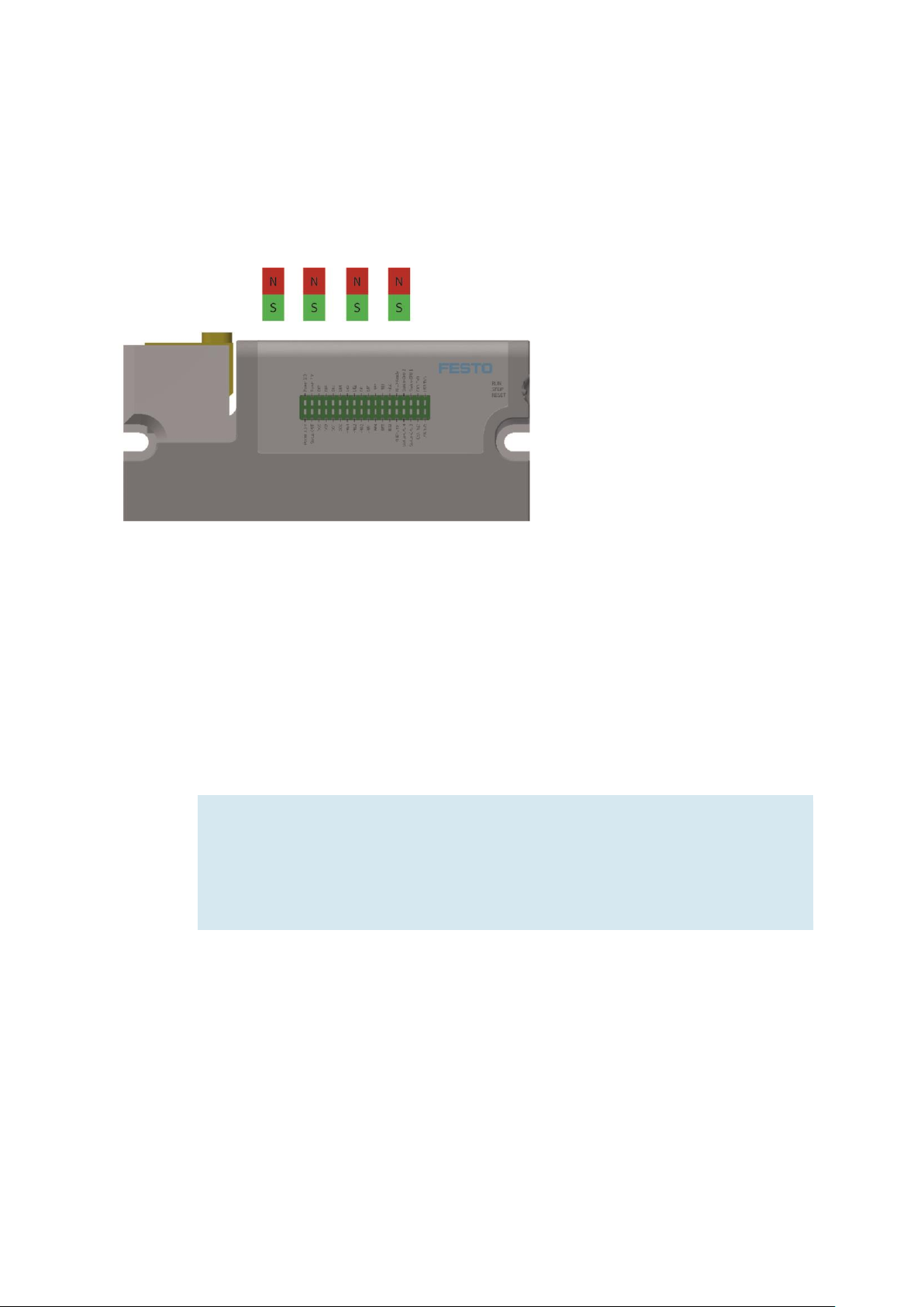
CPS Gate
62 © Festo Didactic 8075265
12 Magnetic field sensors
Four integrated magnetic field sensors for detecting the workpiece carrier are located on the top of the
device. The positions of sensors -BE1 … -BE4 are identified. The magnets must be mounted so that the south
pole points towards the sensor.
13 RFID
An RFID write/read unit (radio frequency identification) is integrated into the CPS Gate. It can be used to
read a 13.56 MHz RFID tag (IEC 15693) which is mounted on the workpiece carrier.
The RFID antenna is located on top of the CPS Gate and is identified. The tags should be parallel to the top
of the device at a distance of 1 to 30 mm in order to permit reliable reading/writing.
Note
The RFID module works with inductive signal coupling. Any type of metal located in
proximity to the antenna influences signal transmission.
– Avoid positioning any metallic materials close to the antenna and the tag.
– Avoid positioning more than one tag in close proximity to the antenna.
Page 63

CPS Gate
© Festo Didactic 8075265 63
14 NFC
The integrated NFC module (near field communication) makes it possible to configure the device’s
parameters for the application. Data are stored to 512 bytes of retentive memory. Write/read access to this
memory is also possible for CODESYS.
The NFC antenna of the CPS Gate is located on top of the device and is identified. The mobile device should
be moved in to a distance of no greater than 10 cm in order to permit communication. If necessary, the
mounting position of the external device’s NFC antenna has to be determined with the help of the technical
documentation.
15 Mode selector
The switch has 3 positions: RUN
STOP
RESET
The mode selector can be used to:
• Control operation of IEC applications
• Enter settings to the device
• Trigger resetting of the device
The following table lists the functions of the mode selector.
Page 64

CPS Gate
64 © Festo Didactic 8075265
During operation
Final status
or action
Mode
selector
position
Sequence
Description
LED status indication
Run
RUN All IEC applications are processed and can be
stopped and started via the CODESYS IDE.
RFID
is active
NFC
not active in this case
Alternatively, NFC can be activated or
deactivated via an IEC application.
Stop
STOP All existing IEC applications are stopped at
the end of the respective cycle and can no
longer be started via the CODESYS IDE.
NFC
NFC is a parameters configuring interface –
it’s parameters can only be configured in the
voltage-free state or in the “STOP” position
of the CODESYS run switch.
Reset CODESYS,
warm start
RESET
From > 1
to < 2 s
All IEC applications are reset by means of
“warm reset”.
Reset
RESET
> 4 s
Retain data are saved. The IEC applications
are then ended.
Reset
RESET
> 8 s
Reboot.
Page 65

CPS Gate
© Festo Didactic 8075265 65
Switching on the power supply and PoR (power on reset)
Final status
or action
Mode
selector
position
Sequence
Description
LED status indication
RUN An existing boot project is loaded and
applications included in it are started.
STOP An existing boot project is not loaded and
applications included in it are not started. In
order for the boot project to be loaded, the
device must be disconnected from the power
supply and switched back on in the RUN
mode.
A new project can be loaded to the controller
and a new boot project can be generated
with the help of the CODESYS IDE.
Page 66
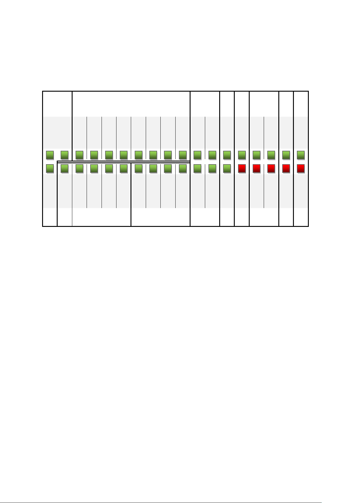
CPS Gate
66 © Festo Didactic 8075265
16 Diagnostic display
The 36 LEDs indicate the following statuses:
Power
Digital inputs
Hall
sensors
RF
ID
No
function
C
A
N
U
S
B
Power I/O Power 5 V DI7
DI6
DI5
DI4
DI3
DI2
DI1
DI0
-BE2
-BE1
-BG1
RFID ready
Status CPU 2 Status CPU 1 CAN TxD
USB TxD
Power 3.3 V STAT OUT DO3
DO2
DO1
DO0
-MB4
-MB3
-MB2
-MB1
-BE4
-BE3
-BG2
RFID error
Status CPU 4 Status CPU 3 CAN RxD USB RxD
Digital outputs
Pneumatic valves
Hall
sensors
RF
ID
No
function
Page 67

CPS Gate
© Festo Didactic 8075265 67
LED designation
Diagnosis when LED is on …
Power I/O
+24 V dc supply voltage for the digital inputs/outputs, terminal X8, 1+2, is on. Supply
voltage for the CPU must be on.
Power 5 V
+24 V dc supply voltage for the digital CPU, terminal X11, 1+2, is on. Internal 5 V
controller OK
Power 3.3 V
+24 V dc supply voltage for the digital CPU, terminal X11, 1+2, is on. Internal 3.3 V
controller OK
DI0
Input X6, 1 high
DI1
Input X6, 4 high
DI2
Input X7, 1 high
DI3
Input X7, 4 high
DI4
Input X9, 1 high
DI5
Input X9, 4 high
DI6
Input X10, 1 high
DI7
Input X10, 4 high
DO0
Output X8, 6 switched
DO1
Output X8, 4 switched
DO2
Output X11, 6 switched
DO3
Output X11, 4 switched
STAT OUT
Output OK, no over-temperature or short-circuit
-MB1
Valve 1 switched, stopper up
-MB2
Valve 2 switched, stopper down
-MB3
Valve 3 switched
-MB4
Valve 4 switched
Page 68
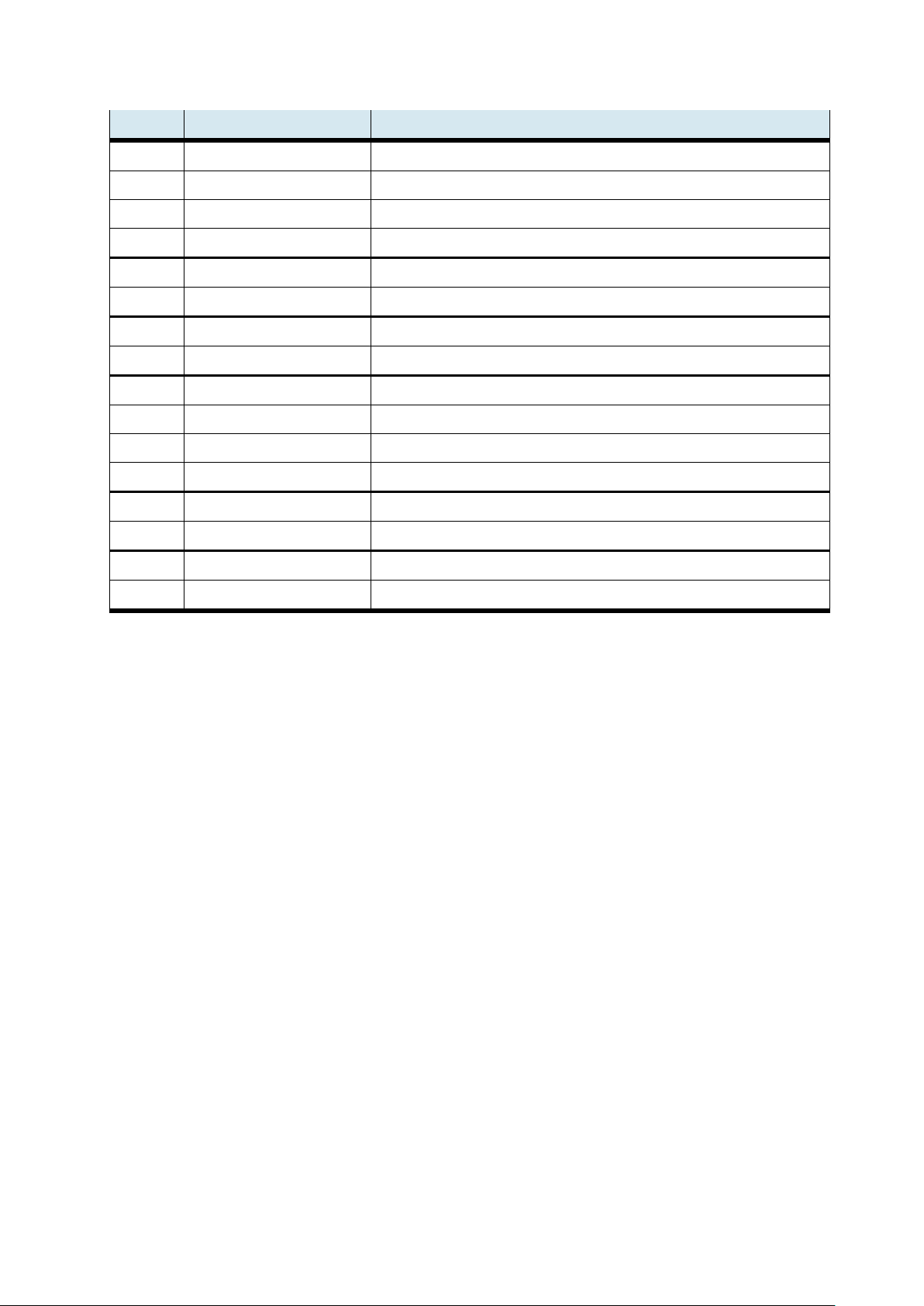
CPS Gate
68 © Festo Didactic 8075265
LED designation
Diagnosis when LED is on …
-BE1
Sensor -MB1 detects a magnetic field (south oriented)
-BE2
Sensor -MB2 detects a magnetic field (south oriented)
-BE3
Sensor -MB3 detects a magnetic field (south oriented)
-BE4
Sensor -MB4 detects a magnetic field (south oriented)
-BG1
Stopper in bottom end position
-BG2
Stopper in top end position
RFID ready
No function
RFID error
No function
Status CPU 1
No function
Status CPU 2
No function
Status CPU 3
No function
Status CPU 4
No function
CAN TxD
Transmitting data
CAN RxD
Receiving data
USB TxD
Transmitting data
USB RxD
Receiving data
Page 69
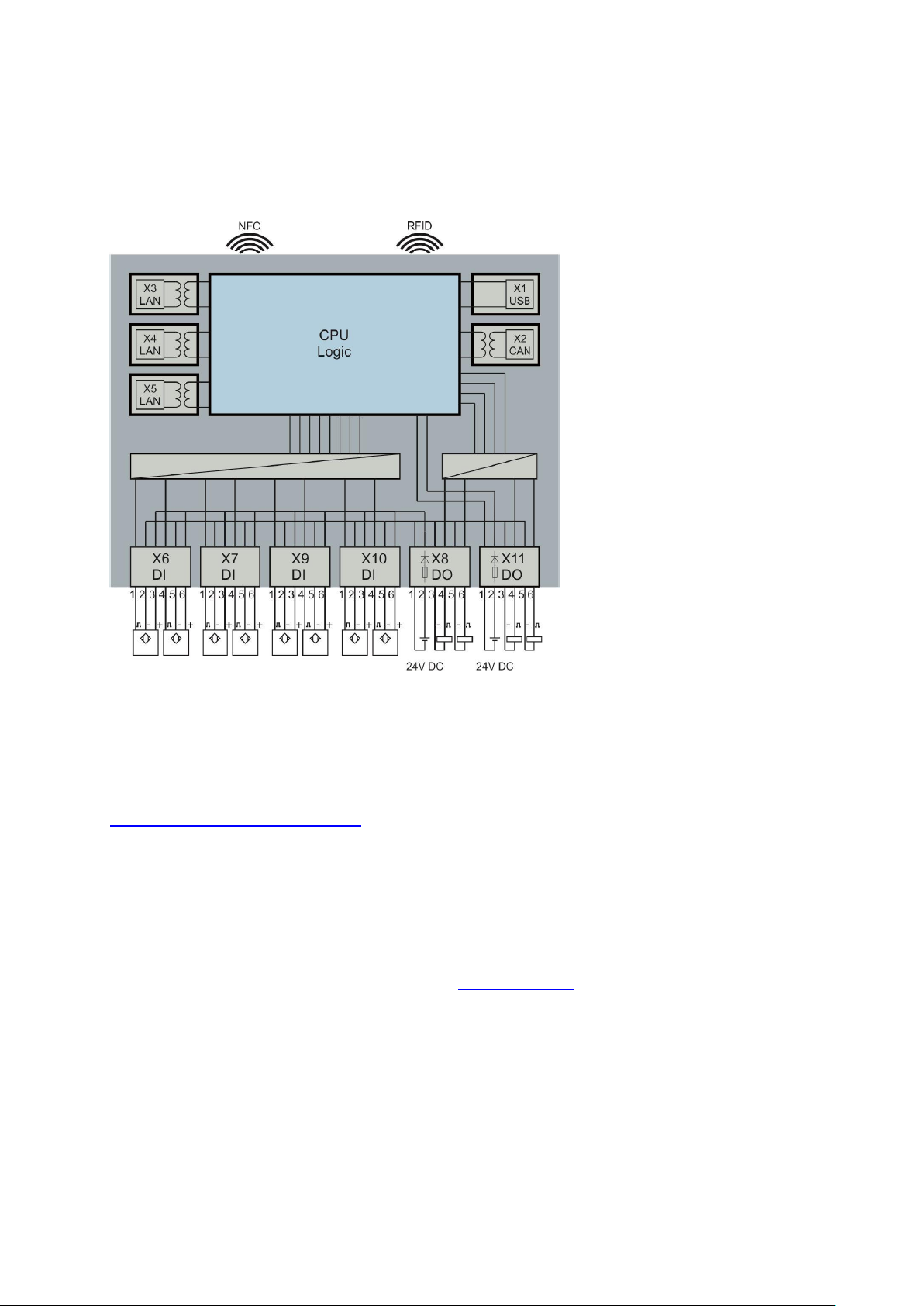
CPS Gate
© Festo Didactic 8075265 69
17 Wiring diagram
General application example:
18 Software
The most current data are available to our customers from our service portal at
https://www.cp.community.festo.com. Login credentials can be supplied upon request.
18.1 CODESYS programming environment
Program applications can be conveniently prepared for the CPS Gate with the help of the CODESYS
programming environment. CODESYS permits complete programming in accordance with IEC 61131-3. The
program’s user interface is available free of charge at www.codesys.org. The system prerequisites can be
found on this website.
At least v 3.5, service pack 10, is required for use of the library functions. This version is also referred to with
the designation 3.5.10.x.
Page 70
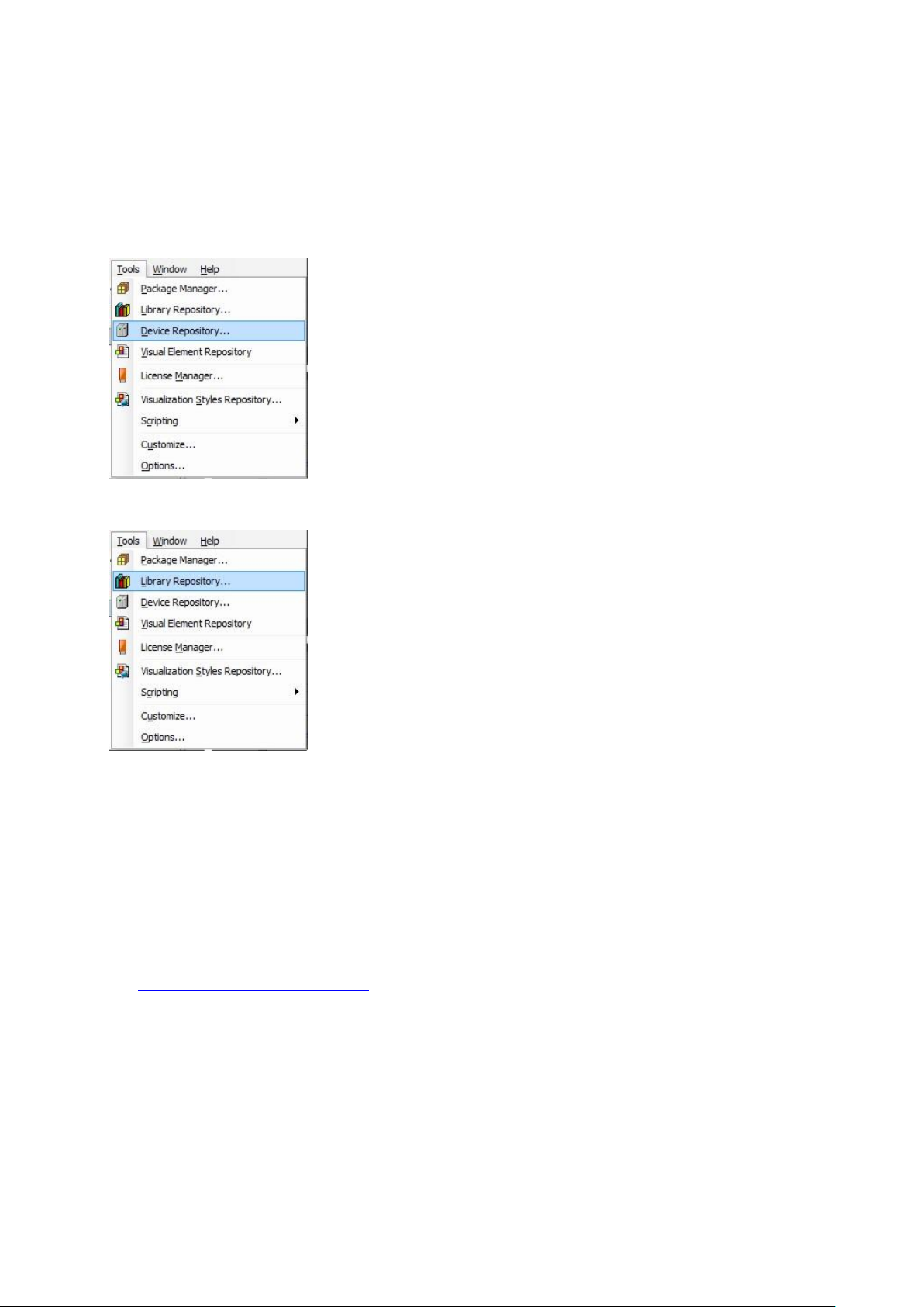
CPS Gate
70 © Festo Didactic 8075265
In addition to the CODESYS programming interface, a device description file and a library file are also
required. Both files are available from Festo’s service portal.
These files are installed in CODESYS via the “Tools” tab. Further details concerning programming can be
found in the CODESYS documentation.
Installing the device description file
Installing the library file
18.2 Web visualization
The version of CODESYS on the device supports CODESYS web visualization. This is based on HTML5 and
can thus be implemented using any browser which supports the HTML5 canvas element. Enter the following
address to your browser’s address line in order to invoke web visualization:
http://<IP address>:<port number>/webvisu.htm
e.g. http://192.168.1.254/webvisu.htm
IP address 192.168.2.254 and port 80 are used as default settings for web visualization.
Page 71

CPS Gate
© Festo Didactic 8075265 71
18.3 IP address
The device’s IP address is set to 192.168.2.254 upon shipment from the factory.
This address can be read and changed via the NFC interface, as well as by the CODESYS application.
NFC memory map
Byte 3
Byte 2
Byte 1
Byte 0
192
168
002
254
Setting the IP address with an NFC-compatible mobile device
• Activate the NFC antenna by setting mode selector S1 to the middle position (Stop).
• The desired IP address sections can be written to address bytes 0 – 3 with a suitable NFC app.
Setting the IP address from CODESYS
The “OPAK_RFID” library is available for reading/writing the IP address.
The following code fragment demonstrates writing of the IP address:
// In order to read and write the IP address via CODESYS, the NFC antenna doesn’t
// have to be switched on
IF bWriteIP THEN
Address_IP := 16#C0A86479 // 192.168.100.121
NumberOfWiteBytes := ELA_OPAK_RFID.writeToNFC( addr := ELA_OPAK_RFID.IP,
Len := SIZEOF (Address_IP),
Buf := ADR(Address_IP),
Res := ADR(Result)
);
bWriteIP := false;
END_IF
Page 72

CPS Gate
72 © Festo Didactic 8075265
19 Product labeling
1 Product approvals
2 Manufacturer’s address
3 Technical data
4 Notes on disposable
5 Safety instructions and warnings
1 Product designation
2 Production month
3 Part number (order number,
Hardware Version Identification Number, HVIN)
4 Production year
5 Version Vx.x/y
x.x = hardware version,
y = firmware version
6 Barcode
7 Serial number
8 Internal ID number
20 Maintenance and cleaning
The device is maintenance-free. Use a slightly damp, lint-free cloth for cleaning without any abrasive,
chemical, or solvent-containing cleaning agents.
21 Storage and transport
The device is shipped in the manufacturer’s original packaging along with included accessories. This
packaging provides adequate protection for the device during transport and storage. Permissible storage
conditions are listed in the technical data.
Page 73
CPS Gate
© Festo Didactic 8075265 73
22 Scope of delivery
• CPS Gate
• Protective covers for electrical connection sockets
• User guide
• Mounting materials
• Plug connector QSM, reducer: 4 mm --> 3 mm, QSM-4-3, Festo AG & Co. KG order number 153326
• 300 mm length of plastic pneumatic tubing, PUN-3x0,5-SI
23 Accessories and spare parts
• Festo Didactic tabletop SELV/PELV power pack with energy limiting, Festo Didactic
order number 8049633
• Plastic pneumatic tubing, silver, 50 m: PUN-3x0,5-SI
• Replacement socket connectors for -X6 … -X11: Socket connector with gripping plate,
cable bundling function and
unlocking aid, 6-pin, grid dimension: 3.5 mm
Wago order number 2091-1106/002-000
• RFID tag, ISO 15693, Turck type: TW-R16-B128, Turck order number 6900501
24 Disposal
Electronic waste contains reusable materials and must not be disposed of with the trash.
Bring electronic waste to a designated collection point.
25 CE declaration of conformity
Simplified EU declaration of conformity in accordance with article 10, section 9 of guideline 2014/53/EU:
Festo Didactic SE hereby declares that the wireless unit with the designation CPS Gate,
order number 8075267, complies with directive 2014/53/EU.
The complete text of the EU declaration of conformity can be accessed at the following Internet address:
http://www.festo-didactic.com/de-de/service/printmedien/zertifikate-produktkonformitaet
Page 74

CPS Gate
© Festo Didactic 8075265 74
Table des matières
1 Conditions générales d'exploitation des appareils _______________________________________ 76
2 Pictogrammes ____________________________________________________________________ 77
3 Usage normal ____________________________________________________________________ 78
4 Pour votre sécurité ________________________________________________________________ 79
4.1 Remarques importantes ____________________________________________________________ 79
4.2 Engagement de l’exploitant _________________________________________________________ 79
4.3 Engagement des stagiaires _________________________________________________________ 79
5 Instructions de travail et de sécurité __________________________________________________ 80
6 Informations de version ____________________________________________________________ 82
7 Caractéristiques techniques_________________________________________________________ 83
8 Homologations/normes ____________________________________________________________ 85
9 Description ______________________________________________________________________ 87
10 Éléments de raccordement, d'affichage et de commande _________________________________ 88
10.1 Vue arrière _______________________________________________________________________ 88
10.2 Vue de face ______________________________________________________________________ 88
10.3 Vue de dessus ____________________________________________________________________ 89
10.4 Vue de côté ______________________________________________________________________ 89
11 Installation ______________________________________________________________________ 90
11.1 Montage ________________________________________________________________________ 90
11.2 Démontage ______________________________________________________________________ 91
11.3 Connexion électrique ______________________________________________________________ 91
11.3.1 Interface USB ____________________________________________________________________ 92
11.3.2 Interface CAN ____________________________________________________________________ 93
11.3.3 Interfaces Ethernet ________________________________________________________________ 94
11.3.4 Entrées TOR ______________________________________________________________________ 95
11.3.5 Sorties TOR, alimentation électrique __________________________________________________ 96
Page 75

CPS Gate
© Festo Didactic 8075265 75
12 Capteurs de champ magnétique _____________________________________________________ 97
13 RFID ____________________________________________________________________________ 97
14 NFC ____________________________________________________________________________ 98
15 Sélecteur de mode ________________________________________________________________ 98
16 Affichage de diagnostic ___________________________________________________________ 100
17 Schéma de connexion _____________________________________________________________ 103
18 Logiciel ________________________________________________________________________ 103
18.1 Environnement de programmation CODESYS __________________________________________ 103
18.2 Visualisation Web ________________________________________________________________ 104
18.3 Adresse IP ______________________________________________________________________ 105
19 Marquage du produit _____________________________________________________________ 106
20 Maintenance et nettoyage _________________________________________________________ 106
21 Stockage et transport _____________________________________________________________ 106
22 Fourniture ______________________________________________________________________ 107
23 Accessoires, pièces de rechange ____________________________________________________ 107
24 Mise au rebut ___________________________________________________________________ 107
25 Déclaration de conformité CE _______________________________________________________ 107
Page 76

CPS Gate
76 © Festo Didactic 8075265
1 Conditions générales d'exploitation des appareils
Conditions générales d'exploitation des appareils en toute sécurité :
• Dans les établissements industriels ou artisanaux, il conviendra de respecter les directives des
organismes professionnels, et notamment celles des mutuelles d'assurance accident applicables aux
matériels électriques.
• Le laboratoire ou la salle de cours doit être surveillé par un superviseur.
– Un superviseur est un électricien qualifié ou une personne ayant été formée en ingénierie
électrique, connaissant les exigences et les règles en matière de sécurité et dont la formation a été
documentée en conséquence.
Le laboratoire ou la salle de TP doivent être dotés des équipements suivants :
• Il doit exister un dispositif d'ARRÊT D'URGENCE.
– Un ARRÊT D'URGENCE dans la salle de TP ou de cours et au moins un en dehors.
• Le laboratoire ou la salle de cours doit être sécurisé afin que l'alimentation électrique et l'alimentation
en air comprimé ne puissent être activées par des personnes non autorisées. Par exemple, les moyens
suivants peuvent être utilisés :
– par un interrupteur à clé par exemple
– par des distributeurs de mise en circuit verrouillables par exemple
• Le laboratoire ou la salle de cours doit être protégé par des dispositifs à courant différentiel résiduel
(DDR).
– N'utilisez le matériel électrique (tels que blocs d'alimentation, compresseurs, groupes
hydrauliques, etc.) que dans des locaux de formation dotés d'un dispositif différentiel résiduel.
– Utilisez comme dispositif différentiel résiduel un coupe-circuit DDR à courant différentiel ≤ 30 mA,
type B.
• Le laboratoire ou la salle de cours doit être protégé par des dispositifs de protection contre les
surintensités.
– Fusibles ou disjoncteurs.
• Il est interdit d'utiliser tout appareil endommagé ou défectueux.
– L'utilisation d'appareils défectueux doit être immédiatement interrompue et ceux-ci doivent être
retirés du laboratoire ou de la salle de cours.
– Les câbles de connexion, tubes pneumatiques et flexibles hydrauliques endommagés présentent
un risque de sécurité et doivent être retirés du laboratoire ou de la salle de cours.
Page 77
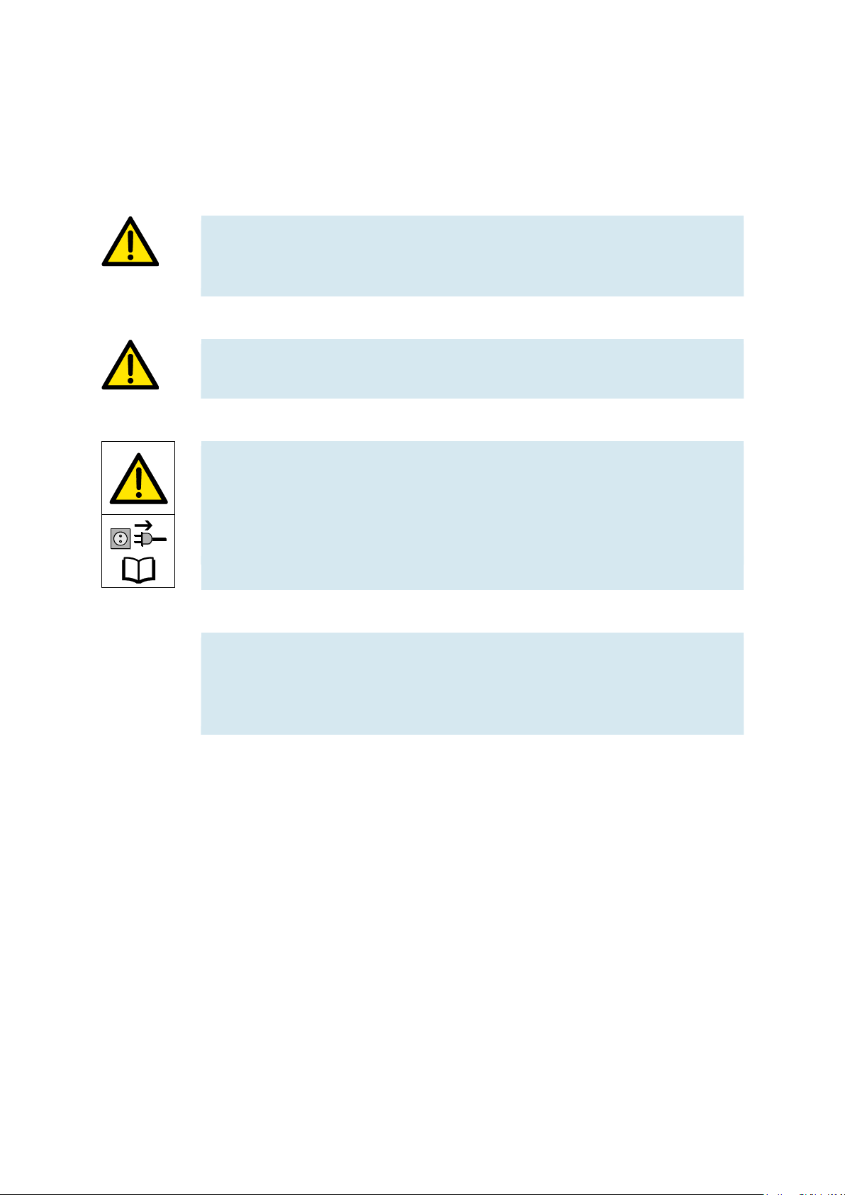
CPS Gate
© Festo Didactic 8075265 77
2 Pictogrammes
Ce document et le matériel décrit comportent des informations sur les dangers potentiels d'une utilisation
non conforme du système. Les pictogrammes utilisés sont les suivants :
Avertissement
… signifie que le non respect peut entraîner de graves dommages corporels ou
matériels.
Attention
… signifie que le non-respect peut entraîner des dommages corporels ou matériels.
Avertissement
… signifie que l'appareil doit être mis hors tension et la fiche secteur débranchée
avant d'effectuer des travaux de montage, de réparation de maintenance et
d'entretien. Conformez-vous au manuel, notamment aux consignes de sécurité. Le
non respect peut entraîner de graves dommages corporels ou matériels.
Nota
… signifie qu'il convient de respecter une consigne opératoire pour se conformer à
l'usage normal de l'appareil. Le non respect des consignes peut entraîner des
dysfonctionnements.
Page 78

CPS Gate
78 © Festo Didactic 8075265
3 Usage normal
Le CPS Gate Festo Didactic ne doit être utilisé que :
• pour un usage normal, c'est-à-dire dans le cadre de l'enseignement et de la formation professionnelle
• Lorsque ses fonctions de sécurité sont en parfait état
Le CPS Gate est construit conformément à l’état de l’art et aux règles techniques reconnues en matière de
sécurité. Une utilisation non conforme peut néanmoins mettre en danger la vie ou la santé de l’utilisateur ou
de tiers ainsi qu'affecter l’intégrité des composants.
Le système de formation de Festo Didactic est exclusivement destiné à la formation initiale et continue dans
le domaine de l’automatisation et de la technique. Il incombe à l’établissement de formation et/ou aux
formateurs de faire respecter par les étudiants les consignes de sécurité décrites dans le présent document.
Festo Didactic décline par conséquent toute responsabilité pour les dommages causés aux étudiants, à
l’établissement de formation et/ou à des tiers du fait de l'utilisation de ce jeu d’équipement en dehors du
contexte d’une pure formation, à moins que ces dommages ne soient imputables à une faute intentionnelle
ou à une négligence grossière de Festo Didactic.
L'automate CPS Gate décrit dans les présentes instructions de service est exclusivement destiné à une
intégration dans la bande transporteuse Festo Didactic
Page 79
CPS Gate
© Festo Didactic 8075265 79
4 Pour votre sécurité
4.1 Remarques importantes
La condition de base de l’utilisation en toute sécurité et du parfait fonctionnement du CPS Gate est de bien
connaître les consignes et prescriptions fondamentales de sécurité. Les présentes instructions de service
contiennent les informations essentielles pour utiliser le système en toute sécurité.
Les instructions de sécurité, notamment, doivent être respectées par tous ceux qui travaillent sur le CPS
Gate. Il convient en outre de respecter les règles et prescriptions de prévention des accidents en vigueur sur
le site d'utilisation.
4.2 Engagement de l’exploitant
L’exploitant s’engage à ne laisser travailler sur l'appareil que des personnes :
• ayant lu et compris les prescriptions fondamentales sur la sécurité au travail et la prévention des
accidents, et initiées à la manipulation de l'appareil,
• ayant lu et compris le chapitre sécurité et les avertissements des présentes instructions de service.
Le travail en toute conscience des dangers et de la sécurité par le personnel doit être vérifié à intervalles
réguliers.
4.3 Engagement des stagiaires
Toutes les personnes chargées de travailler sur l'appareil s’engagent, avant de commencer à travailler, à :
• lire le chapitre sur la sécurité et les avertissements du présent manuel,
• respecter les prescriptions fondamentales sur la sécurité au travail et sur la prévention des accidents.
Avertissement
Tous les équipements de sécurité de la machine, connectés au CPS Gate doivent être
opérationnels.
La sécurité électrique de la machine doit être assurée et attestée.
Page 80

CPS Gate
80 © Festo Didactic 8075265
5 Instructions de travail et de sécurité
Généralités
• Les étudiants doivent exclusivement travailler sur les montages sous la surveillance d'une
formatrice/d'un formateur.
• Respectez les indications données dans les fiches techniques des différents composants, en particulier
toutes les consignes de sécurité !
• Veillez à ne pas générer des dysfonctionnements susceptibles d'affecter la sécurité.
• Portez votre équipement de protection individuel (lunettes de protection, chaussures de sécurité)
lorsque vous travaillez sur les montages.
Électrotechnique
• Danger de mort en cas d'interruption du fil de protection !
– La continuité du conducteur de protection (jaune/vert) ne doit être interrompue ni à l'extérieur ni à
l'intérieur de l'appareillage.
– L'isolation du fil de protection ne doit être ni endommagée ni supprimée.
• Danger de mort par montage en série de blocs d’alimentation !
Des tensions de contact > 25 V AC ou > 60 V DC ne sont pas admissibles.
Des tensions > 50 V AC ou 120 V DC peuvent, en cas de contact, être mortelles.
– Ne montez pas de sources de tension en série.
• Danger de mort par électrocution !
Protégez de tout contact direct les sorties des blocs d’alimentation (douilles/bornes de sortie) et les
câbles qui y sont raccordés.
– Utilisez uniquement des câbles à isolation et rigidité diélectrique suffisantes.
– Utiliser des douilles de sécurité protégées contre les contacts fortuits.
• Mettre hors tension !
– Coupez l'alimentation électrique avant de travailler sur le montage.
– Notez que certains composants peuvent avoir stocké de l'énergie électrique. Vous trouverez des
informations à ce sujet dans les fiches techniques et instructions de service des composants.
– Attention !
Des condensateurs intégrés à l'appareil peuvent encore être chargés même après coupure de
toutes les sources de tension.
• Connexion et déconnexion de raccordements électriques
– N'effectuez les raccordements électriques qu'en l'absence de tension.
– Ne déconnectez les raccordements électriques qu'en l'absence de tension.
Page 81

CPS Gate
© Festo Didactic 8075265 81
• Ne dépassez pas les courants admissibles sur les câbles et les appareils.
– Comparez toujours les courants aux valeurs admissibles des appareils, câbles et fusibles.
– En cas de non-concordance, utilisez un fusible distinct monté en amont comme protection contre
les surintensités.
• Utilisez pour les connexions électriques uniquement des câbles équipés de fiches mâles de sécurité.
• Posez les câbles de liaison de sorte à éviter les pliures et cisaillements.
• Ne posez pas de câble sur des surfaces chaudes.
– Les surfaces chaudes sont repérées par un symbole de mise en garde adéquat.
• Veillez à ce que les câbles de liaison ne soient pas en permanence sous traction.
• Sauf indications contraires dans les caractéristiques techniques, l'appareil ne possède pas de fusible
intégré.
• Pour débrancher les câbles de liaison, tirez sur les fiches de sécurité, pas sur les câbles.
• En cas de
– traces visibles d'endommagement,
– fonction défectueuse,
– stockage impropre ou de
– transport non conforme
l'utilisation sans danger de l'appareil n'est plus assurée.
– Coupez immédiatement l'alimentation.
– Empêchez toute remise en marche involontaire de l'appareil.
Pneumatique
• Mettre hors pression !
– Coupez l'alimentation pneumatique avant de travailler sur le montage.
– Vérifiez à l'aide de manomètres que le montage est bien hors pression.
– Il se peut aussi que de l'énergie soit stockée dans des accumulateurs pneumatiques. Vous
trouverez des informations à ce sujet dans les fiches techniques et instructions de service des
composants.
• Ne dépassez pas la pression maximale admissible de 600 kPa (6 bar).
• Ne mettez l'air comprimé en circuit qu’après avoir branché et fixé tous les tuyaux.
• Ne débranchez pas de tuyaux sous pression.
• Risque de blessure à la mise sous pression !
Des vérins peuvent se mettre en mouvement intempestivement.
• Risque d’accident par sortie de la tige de vérin !
– Positionnez toujours les vérins pneumatiques de sorte qu'aucun obstacle n'entrave
la course de la tige.
– Veuillez vous assurer que la tige de vérin ne puisse pas heurter de composants fixes de la structure.
• Risque d'accident en cas de détachement intempestif de tuyaux !
– Utilisez des tuyaux aussi courts que possible.
– Si un tuyau se détache : coupez immédiatement l'alimentation pneumatique.
Page 82

CPS Gate
82 © Festo Didactic 8075265
• Avant de désassembler le montage, coupez l’alimentation en air comprimé.
• Bruit produit par l'échappement d'air comprimé !
– Le bruit produit par l'échappement d'air comprimé peut nuire à l'ouïe. Réduisez le bruit en utilisant
des silencieux ou portez un casque anti-bruit si le bruit est inévitable.
– Tous les orifices d'échappement des composants des jeux d'équipement sont équipés de
silencieux. Ne retirez pas ces silencieux.
Attention !
Toute réparation ou modification inappropriée peut être la source d'états de
fonctionnement imprévisibles. N'éffectuez pas de réparation sur l'appareil.
6 Informations de version
La description se rapporte aux versions suivantes :
– Automate Festo CPS Gate version 1.0/0
– Progiciel CODESYS V3 provided by Festo (pbF)
La présente description contient des informations sur le fonctionnement, le montage, l'installation et la mise
en service du CPS Gate
Version
Description
V1.0/0
Série initiale validée
Page 83

CPS Gate
© Festo Didactic 8075265 83
7 Caractéristiques techniques
Caractéristiques techniques
CPU
Processeur
Cortex-A9, Single Core, 800MHZ
Horloge en temps réel
Disponible, secourue pendant 4 semaines max. par Gold Cap
Mémoire
4 Go RAM, 1 Go flash
Tampon
1 Mo de données retain en mémoire flash
Logiciel / fonctionnalités
Système d'exploitation
Embedded Linux 4.00
Programmation d'API
CODESYS V3 (CS3)
Programmation IHM
CODESYS V3 WebVisu (WV)
Client ou serveur Ethernet TCP Modbus
Réalisable via bibliothèque CEI
Maître EtherCAT (optionnel)
Intégré dans CODESYS V3 (CS3)
Maître CANopen
Réalisable via bibliothèque CEI
OPC UA (optionnel)
Intégré dans CODESYS V3 (CS3)
Interfaces électriques
X1
Diagnostic USB (connecteur de périphérique USB type B)
X2
CAN selon ISO11898 à séparation galvanique, RJ45
X3 … X5
Interface Ethernet, 100BASE-T, RJ45 à fonction de commutateur à 3 ports
X6
Entrées TOR DI0, DI1
Tension d’entrée
Fréquence max.
Temporisation d’entrée
Surtension
Puissance dissipée
Tension min. High
Tension max. Low
24 V DC, EN 61131-2 type 1
100 Hz
≤ 10 ms
33 V
0,2 W par entrée ;
alimentation 24 mA par entrée
15 V
5 V
X7
Entrées TOR DI2, DI3
X9
Entrées TOR DI4, DI5
X10
Entrées TOR DI6, DI7
X8
Sorties TOR DO0, DO1
Alimentation
entrées/sorties TOR
Tension de sortie
Courant de sortie
Courant résiduel
(selon DIN)
Charge résistive
Fréquence de
commutation
Ohm/inductive
Protection contre les
courts-circuits /
protection thermique
Limitation du courant
Fusible
Puissance dissipée
24 V DC, EN 61131-2 type 1
0,5 A
Max. 2 A (à FM 50 %)
Nominale 48 W
100 Hz
0,7 A par canal
2 A pour courant résiduel
0,2 W par sortie
X11
Sorties TOR DO2, DO3
Alimentation CPU
Page 84
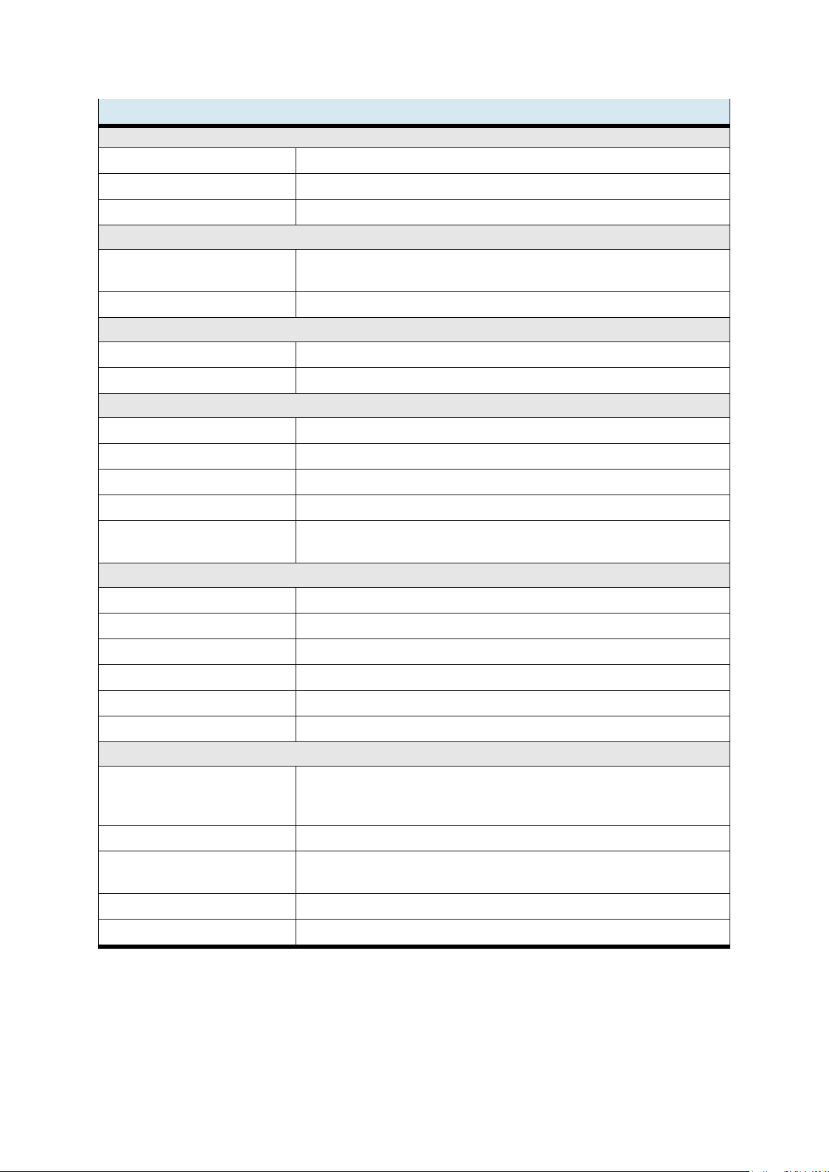
CPS Gate
84 © Festo Didactic 8075265
Caractéristiques techniques (suite)
Interfaces radio
NFC pour la configuration
4 ko EEPROM, ISO 15693
RFID pour les fonctions logistiques
Plot de lecture / écriture 13,56 MHz multiprotocole à antenne intégrée
Puissance émettrice RFID
49,83 dBµV/m @ 3m (-45,4 dBm ±2dBm)
Capteurs / actionneurs internes
Capteurs à effet Hall
4 capteurs de champ magnétique pour la détection du porte-pièce
2 capteurs de position du stoppeur.
Stoppeur
Stoppeur pneumatique Applikator, raccord pneumatique de 3 mm, 600 kPa max. (6 bars)
Eléments de commande et d’affichage
S1
Sélecteur de mode (BAS) pour API
LED d'état
36 LED de signalisation de fonctionnement et d'état
Caractéristiques mécaniques
Dimensions hors tout (L x H x P)
120 x 144 x 30 mm
Poids
Environ 660 g
Boîtier
Boîtier en aluminium avec couvercle en plastique
Degré de protection
IP20, selon EN 60529
Montage
Profilé d'aluminium extrudé 40 mm,
le montage doit assurer la conduction thermique entre l'appareil la structure de la machine
Conditions de service
Température de service
5 °C …40 °C
Température de stockage
-20 °C …70 °C
Humidité relative de l'air en service
10 % ...5 % sans condensation
Humidité relative de l'air en entrepôt
5 %...85 % sans condensation
Refroidissement
Dissipateur de chaleur passive, la convection doit être possible
Exploitation de l'appareil
Utilisation en intérieur seulement jusqu'à 3000 m au-dessus du niveau de la mer
Caractéristiques de connexion électrique
Tension d'alimentation
24 V DC (20,4 V….28,8 V), protégé contre l'inversion de polarité
alimentation uniquement par un bloc d'alimentation TBTS/TBTP avec limitation d'énergie,
fusible en amont 4 A à action retardée
Puissance absorbée
60 W max.
Puissance absorbée par les
distributeurs
4x 1 W (4x 40 mA)
Consommation de la CPU
240 mA
Consommation des sorties TOR
4x 500 mA
Page 85

CPS Gate
© Festo Didactic 8075265 85
8 Homologations/normes
Homologations
Marquage CE selon
Directive Radio Equipment Device (RED)
Spectre : ETSI EN 300330
Sécurité EN 61131-2
CEM ETSI EN 300489-1, ETSI EN 301489-3
EN 61131-2
Directive RoHS
EN 50581
RCM
Autorisation de mise sur le marché Australie
FCC
FCC ID : 2AMRG-CPSGATE
IC
IC : 22929-CPSGATE
For use in USA
FCC Statement in accordance with CFR 47, subpart 15.19
This device complies with part 15 of the FCC rules. Operation is subject to the following two conditions:
3. this device may not cause harmful interference, and
4. this device must accept any interference received, including interference that may cause undesired
operation.
No changes shall be made to the equipment without the manufacturer’s permission as this may void the
user’s authority to operate the equipment.
FCC RF Exposure Statement:
This equipment complies with FCC radiation exposure limits set forth for an uncontrolled environment. End
users must follow the specific operating instructions for satisfying RF exposure compliance.
This equipment shall be installed and operated with a minimum distance of 1 cm between the user and this
device.
For use in Canada
In accordance with RSS-Gen, section 8.4, all license-exempt radio devices shall state the following:
This device complies with ISED’s license-exempt RSSs. Operation is subject to the following two conditions:
5. This device may not cause interference; and
6. This device must accept any interference, including interference that may cause undesired operation of
the device
Le présent appareil est conforme aux CNR d’Industrie Canada applicables aux appareils radio exempts de
licence. L’exploitation est autorisée aux deux conditions suivantes :
7. l’appareil ne doit pas produire de brouillage ;
8. l’utilisateur de l’appareil doit accepter tout brouillage radioélectrique subi, même si le brouillage est
susceptible d’en compromettre le fonctionnement.
RF Exposure Statement:
Page 86

CPS Gate
86 © Festo Didactic 8075265
The equipment conforms to the RF Exposure Evaluation Limits laid down in RSS 102.
Déclaration d‘exposition RF:
L‘équipement est conforme aux valeurs limites d‘évaluation de l‘exposition aux radiofréquences selon CNR
102.
Page 87

CPS Gate
© Festo Didactic 8075265 87
9 Description
Le CPS Gate est un boîtier de commande multifonctionnel offrant des fonctions d'API. L'environnement de
programmation CODESYS, comprenant des fonctions de bibliothèque étendues, est exécuté sur un noyau
performant.
Par ses nombreuses interfaces industrielles et de médias, il se prête à une mise en œuvre dans un
environnement Industrie 4.0. Automate, capteurs, actionneurs et interfaces de communication sont réunis
sur le CPS Gate et directement en place sur l'application de terrain.
L'interface de communication sans fil NFC permet à l'appareil d'être paramétré pour l'application par un
appareil mobile. L'interface RFID sert à la lecture/écriture permanente des informations du prote-pièce. Les
porte-pièces peuvent en outre être codés par des aimants, détectés par 4 capteurs de champ magnétique
intégrés. Le stoppeur pneumatique sert à arrêter ou autoriser le transfert des porte-pièces. La position de la
tige de piston du stoppeur est détectée par 2 autres capteurs.
Schéma fonctionnel du CPS Gate
Page 88

CPS Gate
88 © Festo Didactic 8075265
10 Éléments de raccordement, d'affichage et de commande
10.1 Vue arrière
1
Réducteur d'échappement des
distributeurs 1, 2
2
Raccord d'alimentation des
distributeurs 1 ... 4
3
Bobines -MB1, -MB2 du stoppeur
interne
4
Raccord de travail du distributeur 3
5
Raccord de travail du distributeur 4
6
Bobine -MB3
7
Bobine -MB4
8
Connecteurs -X8, -X11 pour sorties TOR
et alimentations
9
Connecteurs -X3 ... -X4 pour Ethernet
10
Connecteurs -X6, -X7, -X9, -X10 pour
entrées TOR
11
Connecteur de terre fonctionnelle
12
Connecteur CAN -X2
13
Connecteur USB -X1
10.2 Vue de face
1
Stoppeur
2
Affichage de diagnostic
3
Sélecteur de mode
4
Point de fixation
5
Plaque signalétique
6
Point de fixation
Page 89
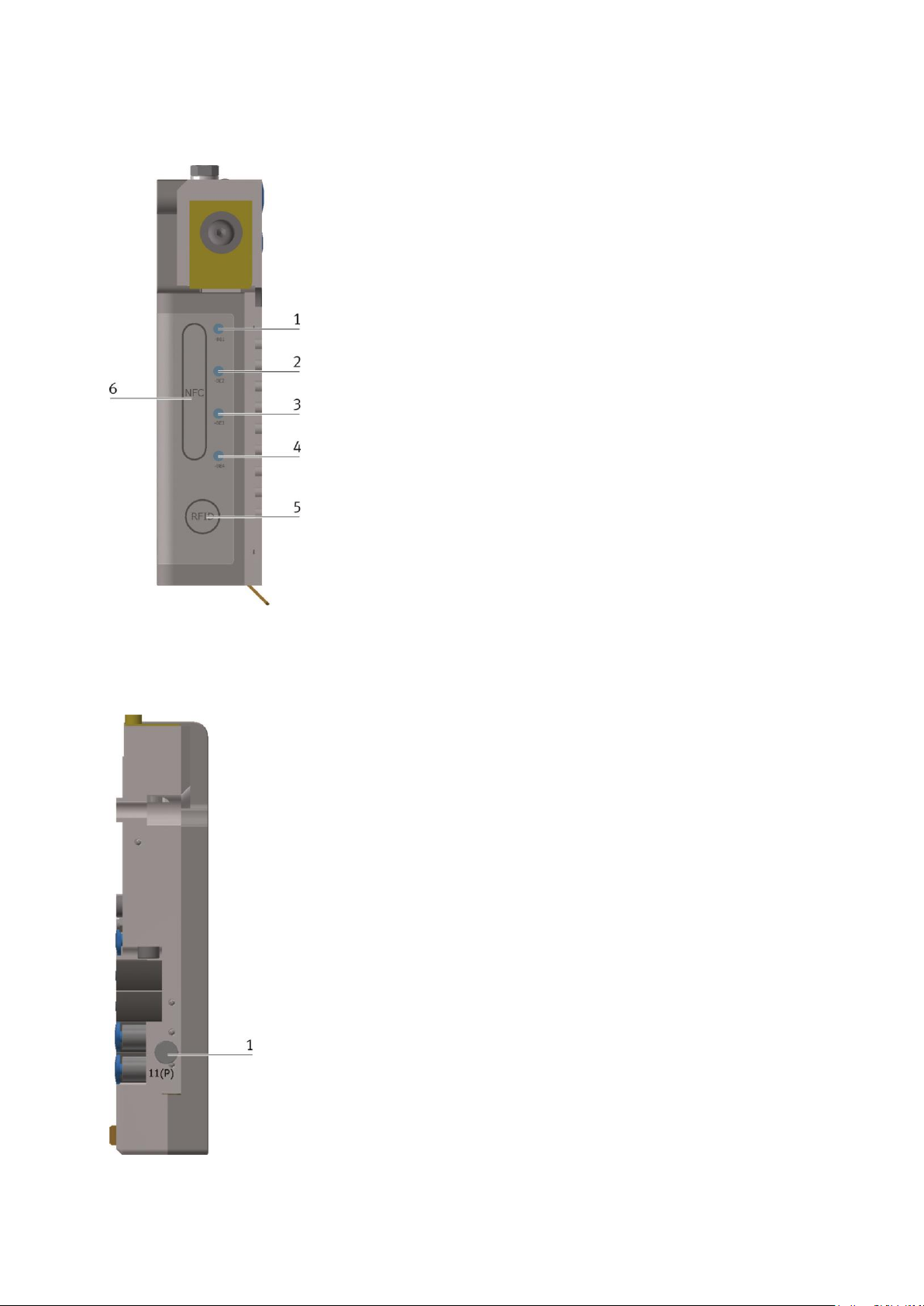
CPS Gate
© Festo Didactic 8075265 89
10.3 Vue de dessus
1
Position capteur de champ
magnétique -BE1
2
Position capteur de champ
magnétique -BE2
3
Position capteur de champ
magnétique -BE3
4
Position capteur de champ
magnétique -BE4
5
Position antenne RFID
6
Position antenne NFC
10.4 Vue de côté
1
Raccord d'alimentation pneumatique
alternatif 11 (P)
Page 90
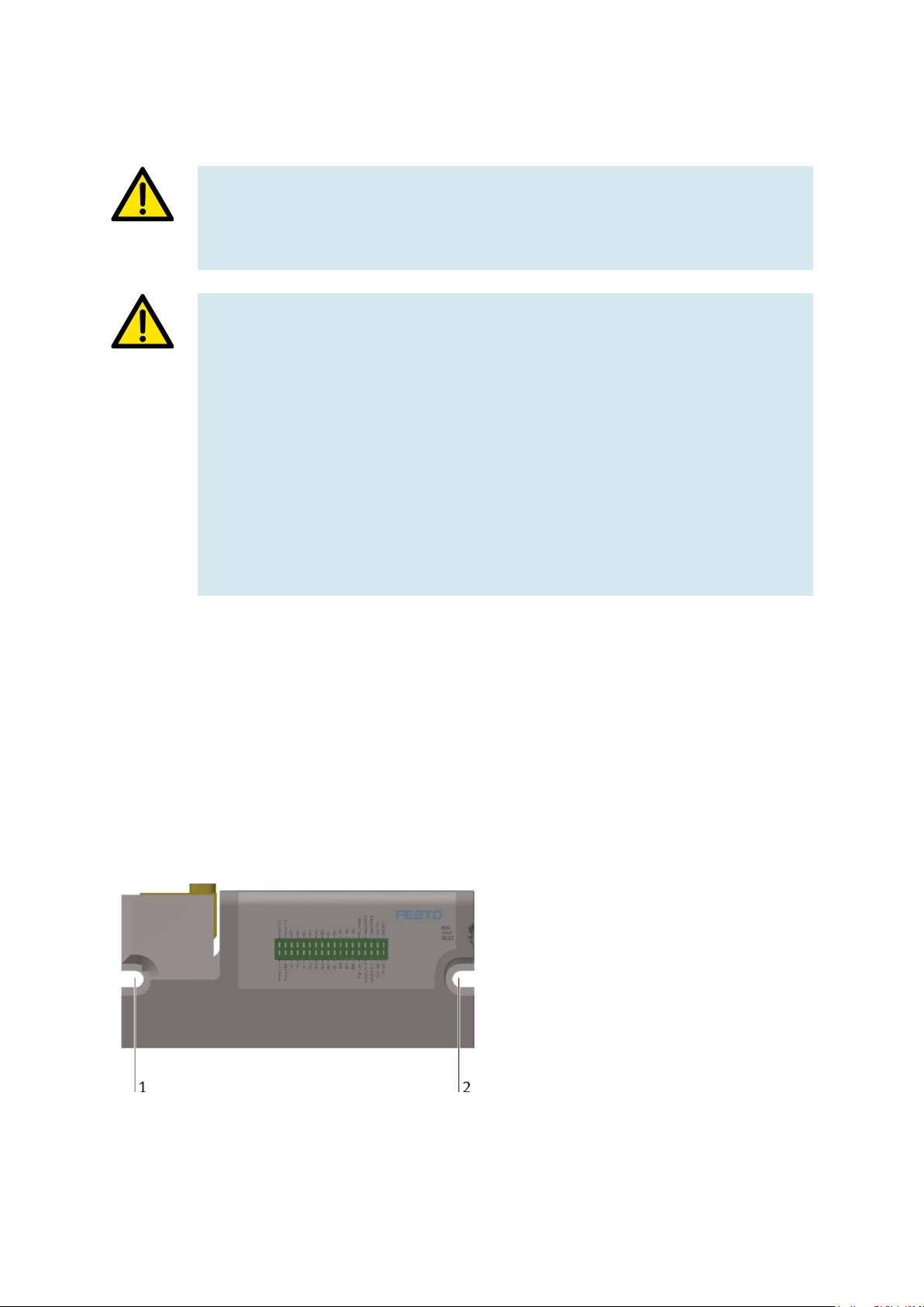
CPS Gate
90 © Festo Didactic 8075265
11 Installation
Avertissement
N'utilisez pas l'appareil pour commander des équipements touchant à la sécurité. La
sécurité fonctionnelle ne peut pas être assurée.
Attention
Les instructions de service doivent avoir été lues attentivement et respectées
scrupuleusement avant l'installation et la mise en service. Conformez-vous aux
consignes de sécurité correspondante.
Attendez, avant la mise en service, que le module soit à la température ambiante. Ne
mettez pas l'appareil sous tension en présence de condensation et attendez qu'il soit
absolument sec.
Pour éviter une surchauffe de l'appareil en cours de fonctionnement,
– n'exposez pas l'appareil directement au rayonnement solaire,
– veillez à ce que les ouïes de ventilation ne soit obturées lors du montage,
– veillez à une circulation d'air suffisante.
11.1 Montage
Vissez l'appareil sur le profilé rectangulaire en aluminium de la bande transporteuse. Les accessoires de
montage sont joints à la fourniture. Montez l'appareil uniquement à la verticale de sorte que le vérin
stoppeur effectue un mouvement vertical. Veillez à ce que le corps en aluminium de l'appareil soit
parfaitement au contact du profilé.
Les connecteurs électriques se trouvent au dos de l'appareil. Ceux-ci doivent être accessibles après le
montage.
Vissez l'appareil aux points de fixation 1 et 2
sur le profilé en aluminium de 40 mm.
Deux vis DIN 912 M5x20 mm ont été jointes
pour ce faire.
Utilisez les écrous pour rainure joints aux
endroits voulus sur le profilé d'aluminium.
Page 91

CPS Gate
© Festo Didactic 8075265 91
Veillez à ce que le rebord saillant (3) s'insère
dans la rainure longitudinale du profil.
11.2 Démontage
Le démontage s'effectue uniquement hors tension. Tous les autres appareils, connectés au CPS Gate,
doivent être hors tension.
Débranchez toutes les connexions électriques de l'appareil. Dévissez ensuite l'appareil. En cas de mise au
rebut, respectez les règlements en vigueur. L'appareil peut être amené à une déchetterie municipale ou être
retourné au constructeur.
Si vous voulez continuer à utiliser l'appareil, obturez les connecteurs électriques avec les capuchons prévus
à cet effet.
11.3 Connexion électrique
Les connexions électriques requises doivent être réalisées hors tension. Obturez les connecteurs inutilisés
avec les capuchons adéquats.
Avant la mise en service, tous les signaux électriques doivent avoir été reliés à un partenaire.
Attention
L'appareil est équipé d'un connecteur de mise à la terre fonctionnelle. Celui-ci doit être
raccordé durablement, avant la mise en service, par une connexion à faible impédance,
au circuit du conducteur de protection de l'installation.
Nota
Utilisez comme conducteur de mise à la terre fonctionnelle une tresse de cuivre souple.
Les conducteurs à âme massive sont déconseillés.
Page 92

CPS Gate
92 © Festo Didactic 8075265
Attention
Alimentez l'appareil uniquement par un bloc d'alimentation TBTS/TBTP avec
limitation d'énergie. Le fusible en amont devra être au maximum de 4 A à action
retardée.
Nota
Pour éviter des couplages parasites, la longueur du câble d'alimentation CC ne devra
pas dépasser 3 m.
Posez tous les câbles de liaison à l'écart de câbles susceptibles de conduire des
perturbations (courant triphasé, câbles de moteur) pour éviter tout couplage parasite.
Nota
Sur le dessus se trouve les antennes intégrées pour la communication RFID et NFC.
Veillez à ne pas les recouvrir.
11.3.1 Interface USB
USB, -X1
Broche
Affectation
Fonction
1
+5 V (500 mA max.)
Tension d'alimentation
2
Data-
3 Data+
4 GND 5 V (masse des signaux)
Tension d'alimentation
Le connecteur USB doit recevoir une tension de service (5 V DC) du partenaire de communication pour que
la communication soit possible.
En cas de parasitage de la communication, il est conseillé de prévoir une séparation galvanique entre le
connecteur USB et l'appareil USB externe pour interrompre la boucle de masse. Vous pouvez utiliser pour
ce faire un concentrateur USB.
Page 93

CPS Gate
© Festo Didactic 8075265 93
11.3.2 Interface CAN
Cette interface se présente sous forme d'un connecteur RJ45 à 8 pôles. Elle est séparée galvaniquement de
la tension d'alimentation de l'appareil.
CAN, -X2
Broche
Affectation
1
2
3
4
5
6
7
8
Shld
CAN-H
CAN-L
GND (masse des signaux pour CAN) couplage HF sur terre fonctionnelle
(1 MOhm || 22 nF)
NF
NF
NF
NF
NF
Blindage, couplage HF sur terre fonctionnelle (1 MOhm || 22 nF)
Remarques
– Les broches 4 … 8 non affectées ne doivent pas être utilisées par le partenaire.
– Vérifiez si, du fait de la structure globale, une résistance de terminaison s'impose.
En règle générale, les résistances de terminaison se trouvent en début et en fin
du câble bus. La valeur de résistance typique est de 120 Ohm.
– Utilisez une paire torsadée blindée.
Nota
Dans le cas d'installation défectueuse et de vitesses de transmission élevées, des
erreurs de transmission de données peuvent survenir en raison d'échos et
d'atténuations de signaux. Les erreurs de transmission peuvent être dues à :
– l'absence de résistance de terminaison entre CAN_L (broche 2)
et CAN_H (broche 1),
– un blindage non connecté,
– des dérivations,
– de grandes distances,
– des câbles inadéquats.
Page 94

CPS Gate
94 © Festo Didactic 8075265
11.3.3 Interfaces Ethernet
Les interfaces Ethernet sont réalisées sous forme de connecteur femelle RJ45 avec fonction de
commutateur.
Le commutateur Ethernet 10/100 Mbit intégré supporte Auto-MDI(X). Vous pouvez utiliser indifféremment
des câbles à conducteurs croisés et des câbles de brassage.
Les connecteurs et câbles sont conforme à CAT 5. Veuillez vous assurer que le connecteur Ethernet du
partenaire est mis à la terre.
Le connecteur de terre fonctionnelle du CPS Gate doit être mis à la terre.
Interfaces -X3, -X4, -X5
Broche
Affectation
Fonction
1
TX+
Transmit Data +
2
TX-
Transmit Data -
3
RX+
Receive Data +
44
n.c.
aucune
5
n.c.
aucune
6
RX-
Receive Data -
7
n.c.
aucune
8
n.c.
aucune
Shld
Boîtier de blindage
connecté à la terre fonctionnelle
Ethernet
3x RJ45 (commutés)
Support de transmission
au moins paire torsadée SF-UTP, 100 Ω, CAT 5,
longueur de câble maximale 100 m
Vitesse de transmission
10/100 Mbit/s
Protocoles
DHCP, DNS, FTP, HTTP, HTTPS, SSH
Page 95

CPS Gate
© Festo Didactic 8075265 95
11.3.4 Entrées TOR
Broches de connexion de l'interface -X6 … -X11
Fabricant : Wago,
Référence : 2091-1106/002-000
-X6, entrées TOR DI0, DI1
Broche
Désignation
Fonction
Nota
1
2
3
DI0
GND
+24 V
Entrée TOR 0
Masse de référence
Tension d'alimentation
avec séparation galvanique
connectée à -X8, 1+3
connectée à -X8, 2. Pour l'alimentation des capteurs
4
5
6
DI1
GND
+24 V
Entrée TOR 1
Masse de référence
Tension d'alimentation
avec séparation galvanique
connectée à -X8, 1+3
connectée à -X8, 2. Pour l'alimentation des capteurs
-X7 entrées TOR DI2, DI3
Broche
Désignation
Fonction
Nota
1
2
3
DI2
GND
+24 V
Entrée TOR 2
Masse de référence
Tension d'alimentation
avec séparation galvanique
connectée à -X8, 1+3
connectée à -X8, 2. Pour l'alimentation des capteurs
4
5
6
DI3
GND
+24 V
Entrée numérique 3
Masse de référence
Tension d'alimentation
avec séparation galvanique
connectée à -X8, 1+3
connectée à -X8, 2. Pour l'alimentation des capteurs
-X9, entrées TOR DI4, DI5
Broche
Désignation
Fonction
Nota
1
2
3
DI4
GND
+24 V
Entrée TOR 4
Masse de référence
Tension d'alimentation
avec séparation galvanique
connectée à -X8, 1+3
connectée à -X8, 2. Pour l'alimentation des capteurs
4
5
6
DI5
GND
+24 V
Entrée numérique 5
Masse de référence
Tension d'alimentation
avec séparation galvanique
connectée à -X8, 1+3
connectée à -X8, 2. Pour l'alimentation des capteurs
Page 96
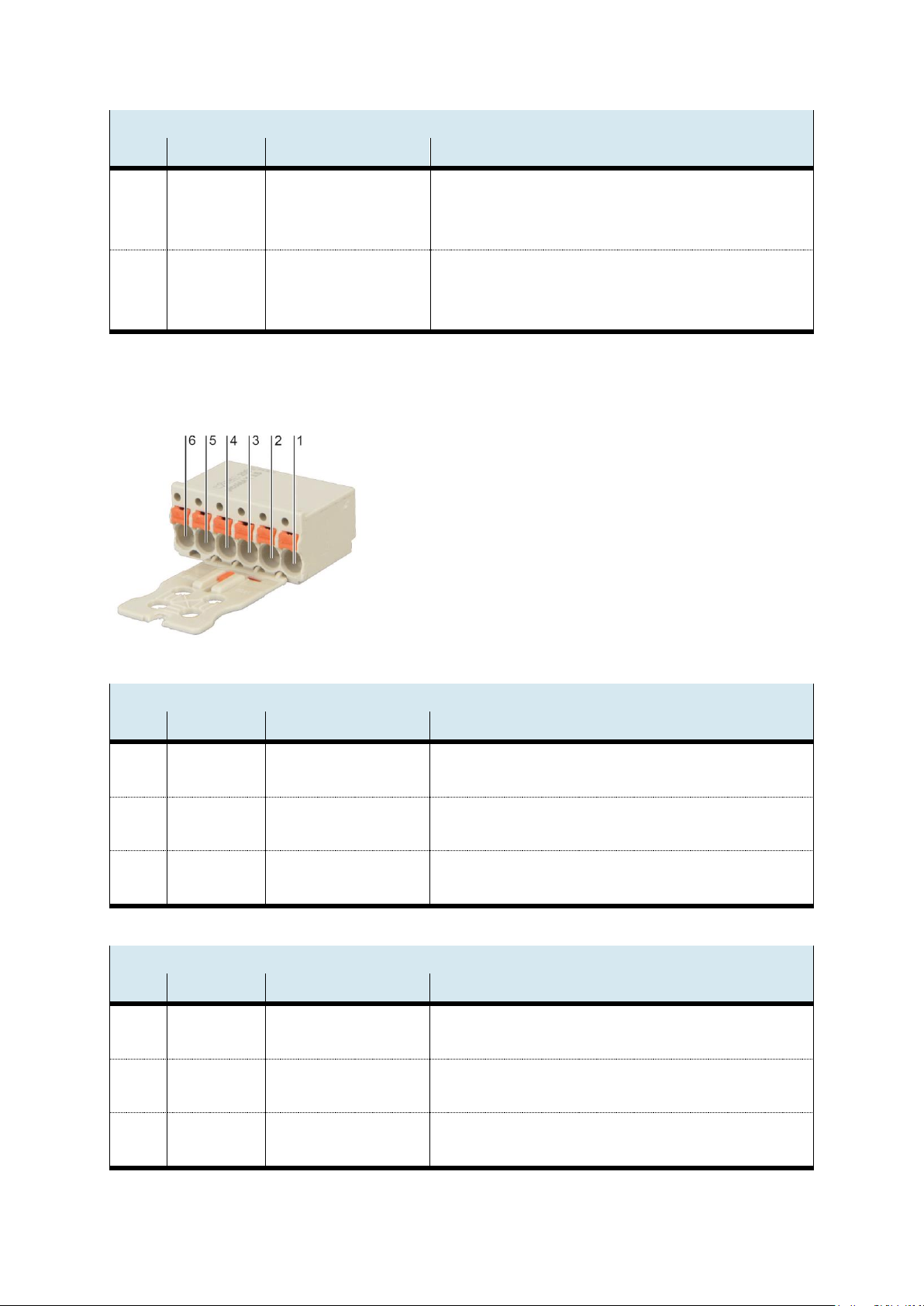
CPS Gate
96 © Festo Didactic 8075265
-X10, entrées TOR DI6, DI7
Broche
Désignation
Fonction
Nota
1
2
3
DI6
GND
+24 V
Entrée TOR 6
Masse de référence
Tension d'alimentation
avec séparation galvanique
connectée à -X8, 1+3
connectée à -X8, 2. Pour l'alimentation des capteurs
4
5
6
DI7
GND
+24 V
Entrée numérique 7
Masse de référence
Tension d'alimentation
avec séparation galvanique
connectée à -X8, 1+3
connectée à -X8, 2. Pour l'alimentation des capteurs
11.3.5 Sorties TOR, alimentation électrique
Broches de connexion de l'interface -X8, -X11
Type : Wago-2091-1406
-X8, sorties TOR DO0, DO1, tension d'alimentation des interfaces numériques
Broche
Désignation
Fonction
Nota
1 2 GND
+24 V
Masse de référence
Tension d'alimentation
GND de la source d'alimentation des interfaces numériques
Source d'alimentation +24 V des interfaces numériques
3 4 GND
DO1
Masse de référence
Sortie TOR 1
connectée à -X8, 1. Potentiel de référence pour DO1
séparé galvaniquement de l'alimentation de la CPU
5 6 GND
DO0
Masse de référence
Sortie TOR 0
connectée à -X8, 1. Potentiel de référence pour DO0
séparé galvaniquement de l'alimentation de la CPU
-X11, sorties TOR DO2, DO3, tension d'alimentation de la CPU
Broche
Désignation
Fonction
Nota 1 2
GND_CPU
+24V_CPU
Masse de référence
Tension d'alimentation
GND borne d'alimentation de la CPU
Borne d'alimentation +24 V de la CPU
3 4 GND
DO3
Masse de référence
Sortie TOR 3
connectée à -X8, 1. Potentiel de référence pour DO1
séparé galvaniquement de l'alimentation de la CPU
5 6 GND
DO2
Masse de référence
Sortie TOR 2
connectée à -X8, 1. Potentiel de référence pour DO0
séparé galvaniquement de l'alimentation de la CPU
Page 97
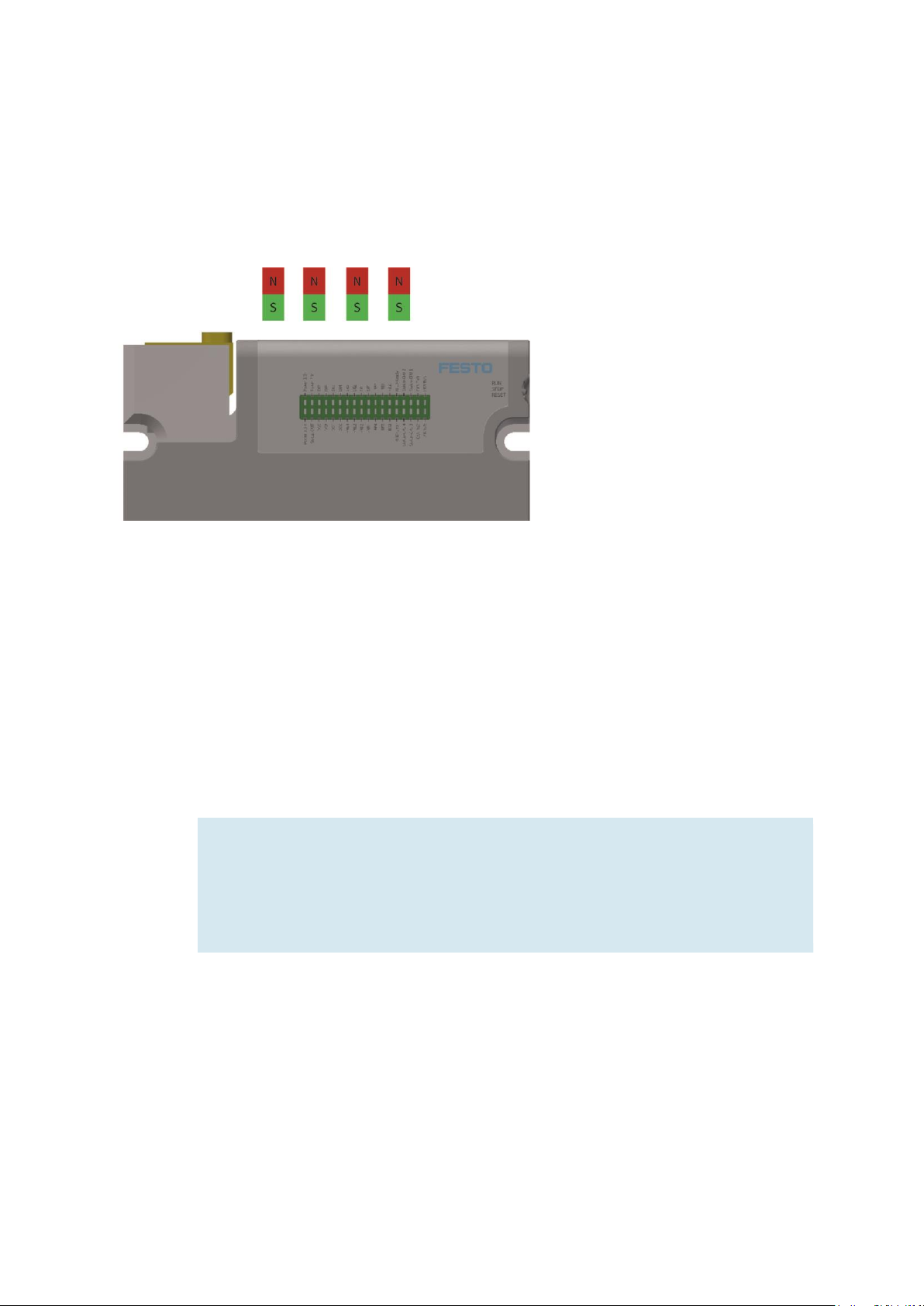
CPS Gate
© Festo Didactic 8075265 97
12 Capteurs de champ magnétique
Sur le dessus de l'appareil se trouvent quatre capteurs de champ magnétique intégrés pour la détection du
porte-pièce. Les positions des capteurs -BE1 … -BE4 sont repérées. Les aimants doivent être montés de
sorte que le pôle sud soit orienté vers le capteur.
13 RFID
Un plot de lecture/écriture RFID (Radio Frequency IDentification) est incorporé au CPS Gate. Il permet de lire
et d'écrire des informations sur un transpondeur RFID 13,56 MHz (CEI 15693), fixé sur le porte-pièce.
L'antenne RFID se trouve à la surface du CPS Gate où elle est repérée. Les transpondeurs doivent se
déplacer à une distance de 1 ... 30 mm et parallèlement à la surface de l'appareil pour assurer une
lecture/écriture fiable.
Nota
Le module RFID fonctionne par couplage inductif des signaux. Tout métal de quelque
nature que ce soit à proximité de l'antenne influence la transmission de signaux.
– Évitez tout matériau métallique à proximité de l'antenne et du transpondeur.
– Évitez de disposer plusieurs transpondeurs dans le champ de l'antenne
Page 98

CPS Gate
98 © Festo Didactic 8075265
14 NFC
Le module NFC (Near Field Communication) intégré permet de paramétrer l'appareil pour l'application. Les
données sont enregistrées dans une mémoire rémanente de 512 octets. CODESYS peut également accéder
en lecture/écriture à cette mémoire.
L'antenne NFC du CPS Gate se trouve sur le dessus de l'appareil où elle est repérée. Approchez l'appareil
mobile jusqu'à environ 10 cm pour que la communication puisse s'établir. Localisez éventuellement la
position de l'antenne NFC sur l'appareil externe à l'aide de la documentation technique.
15 Sélecteur de mode
Le sélecteur adopte 3 positions : RUN
STOP
RESET
Le sélecteur de mode permet de :
• commander le traitement d'applications CEI,
• paramétrer l'appareil,
• déclencher la réinitialisation de l'appareil.
Le tableau ci-après récapitule les fonctions du sélecteur de mode.
Page 99

CPS Gate
© Festo Didactic 8075265 99
En cours de fonctionnement
État final,
ou action
Position
du
sélecteur
Cycle
Description
Indication d'état
(LED)
Run
RUN Toutes les applications CEI sont exécutées,
celles-ci pouvant être arrêtées ou démarrées
par CODESYS IDE.
RFID
est activée
NFC
n'est pas activée ici.
La NFC peut également être activée ou
désactivée par une application CEI.
Stop
STOP Toutes les applications CEI sont arrêtées en
fin de cycle et ne peuvent plus être
redémarrées par CODESYS IDE.
NFC
La NFC étant l'interface de paramétrage, elle
ne peut être paramétrée que hors tension ou
en position « STOP » du sélecteur RUN
CODESYS.
Réinitialisation
CODESYS
Démarrage à chaud
RESET
De > 1 à <
2 s
Toutes les applications CEI sont réinitialisée
par « Reset Warm »
Reset
RESET
> 4 s
Enregistrement des données Retain. Les
applications CEI sont ensuite fermées.
Reset
RESET
> 8 s
Reboot.
Page 100
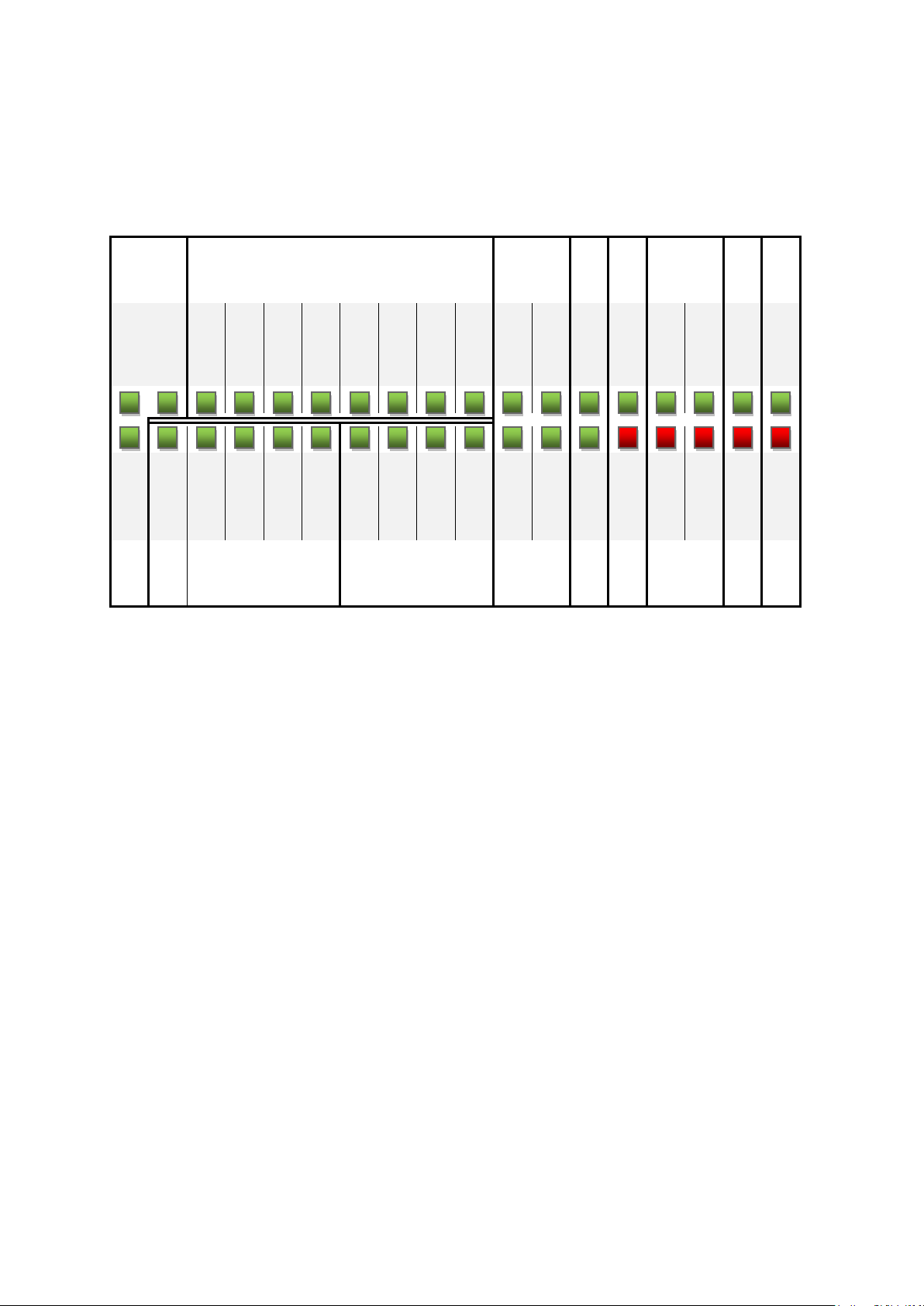
CPS Gate
100 © Festo Didactic 8075265
16 Affichage de diagnostic
Les 36 LED signalent les états suivants :
Power
Entrées TOR
Capteurs
à
effet Hall
RF
ID
Sans
fonction
C
A
N
U
S
B
Power I/O Power 5 V DI7
DI6
DI5
DI4
DI3
DI2
DI1
DI0
-BE2
-BE1
-BG1
RFID Ready État CPU 2 État CPU 1
CAN TxD
USB TxD
Power 3.3 V STAT-OUT
DO3
DO2
DO1
DO0
-MB4
-MB3
-MB2
-MB1
-BE4
-BE3
-BG2
RFID- Error
État CPU 4 État CPU 3 CAN RxD USB RxD
Sorties TOR
Distributeurs
pneumatiques
Capteurs
à
effet Hall
RF
ID
Sans
fonction
 Loading...