

Page 1
SUN G10 2S
bruciatore di gasolio
oil burner
bruleur de fuel
heizölbrenner
quemador de gasóleo
ISTRUZIONI PER L’USO L'INSTALLAZIONE E LA MANUTENZIONE
OPERATING, IN STAL LA TION AND MAIN TE NANCE INSTRUCTIONS
MODE D’EMPLOI, INSTALLATION ET ENTRETIEN
cod. 3544552/3 - 02/2007
BEDIENUNGS-, INSTALLATIONS- UND WARTUNGSANLEITUNG
INSTRUCCIONES DE USO, INSTALACIÓN Y MANTENIMIENTO
Page 2
SUN G10 2S
ItalianoEnglishFrançaisDeutschEspañol
• Leggere attentamente le av ver ten ze con te nu te in que sto libretto di istruzioni in quan to
for ni sco no importanti in di ca zio ni ri guar dan ti
la sicurezza di in stal la zio ne, l’uso la ma nu ten zio ne.
• Il libretto di istruzioni costituisce par te in te gran te ed essenziale del pro dot to e deve essere
conservato dall’utilizzatore con cura per ogni
ulteriore con sul ta zio ne.
• L’installazione e la manutenzione de vo no
essere ef fet tua te in ot tem pe ran za alle norme
vigenti, se con do le istru zio ni del costruttore e
devono essere ese gui te da per so na le pro fes sio nal men te qua li fi ca to.
• Un’errata installazione o una cattiva ma nu ten zio ne possono causare dan ni a persone animale
o cose. È esclusa qual si a si responsabilità del
co strut to re per i danni causati da er ro ri nel l’in stal la zio ne e nel l’uso e comunque per inosservanza delle istruzioni date dal co
stes so
strut to re
• Prima di effettuare qualsiasi ope ra zio ni di pulizia
o di manutenzione, di sin se ri re l’ap pa rec chio
dalla rete di ali men ta zio ne agen do sul l’in ter rut to re del l’im pian to e/o at tra ver so gli appositi
organi di in ter cet ta zio ne.
• In caso di guasto e/o cattivo fun zio na men to
del l’ap pa rec chio, di sat ti var lo, aste nen do si da
qualsiasi ten ta ti vo di ri pa ra zio ne o di intervento
diretto. Ri vol ger si esclu si va men te a per so na le
pro fes sio nal men te qua li fi ca to.
• Dopo aver rimosso l’imballaggio as si cu rar si
del l’in te gri tà del con te nu to.
• Gli elementi dell’imballaggio non de
sere la scia ti alla portata di bam bi ni in quanto
potenziali fon ti di pericolo.
vo no es-
Certificazione
La marcatura CE documenta che gli ap pa rec chi Ferroli sono con for mi ai re qui si ti contenuti nelle
direttive europee ad essi applicabili.
In particolare questo apparecchio è con for me alle se guen ti direttive CEE:
• Direttiva Rendimenti 92/42 re ce pi ta con DPR 15.11.96 n° 660
• Direttiva Bassa Tensione 73/23 (mo di fi ca ta dalla 93/68)
• Direttiva Compatibilità Elet tro ma gne ti ca 89/336 (mo di fi ca ta dalla 93/68) re ce pi ta con DPR 15.11.96
n° 615
Questo simbolo indica “At ten zio ne” ed è po sto in cor ri spon den za di tut te le av ver ten ze
re la ti ve alla si cu rez za. Attenersi scru po lo sa men te a tali pre scri zio ni per evi ta re pericolo e
danni a persone, ani ma li e cose.
Questo simbolo richiama l’at ten zio ne su una nota o un’av ver ten za im por tan te
1. Istruzioni d’uso .......................................................................................3
2. Installazione ............................................................................................4
3. Servizio e manutenzione .......................................................................10
4. Caratteristiche e dati tecnici .................................................................16
Certificato di garanzia ..............................................................................18
2
Cod. 35445523 - 02/2007 (Rev. 00)
Page 3
SUN G10 2S
1. ISTRUZIONI D’USO
1.1 Presentazione
Gentile Cliente,
La ringraziamo di aver scelto SUN G10 2S, un bruciatore Ferroli di concezione avanzata, tecnologia
all’avanguardia, elevata affidabilità e qualità costruttiva.
SUN G10 2S è un bruciatore a gasolio, la cui elevata compattezza e disegno originali lo rendono adatto
all’impiego sulla maggior parte delle caldaie oggi presenti sul mercato. La cura nel progetto e nella produzione industriale ha permesso di ottenere una macchina ben equilibrata, dagli alti rendimenti, bassi
tenori di emissioni CO ed NOx ed una fiamma molto silenziosa.
1.2 Istruzioni per il funzionamento
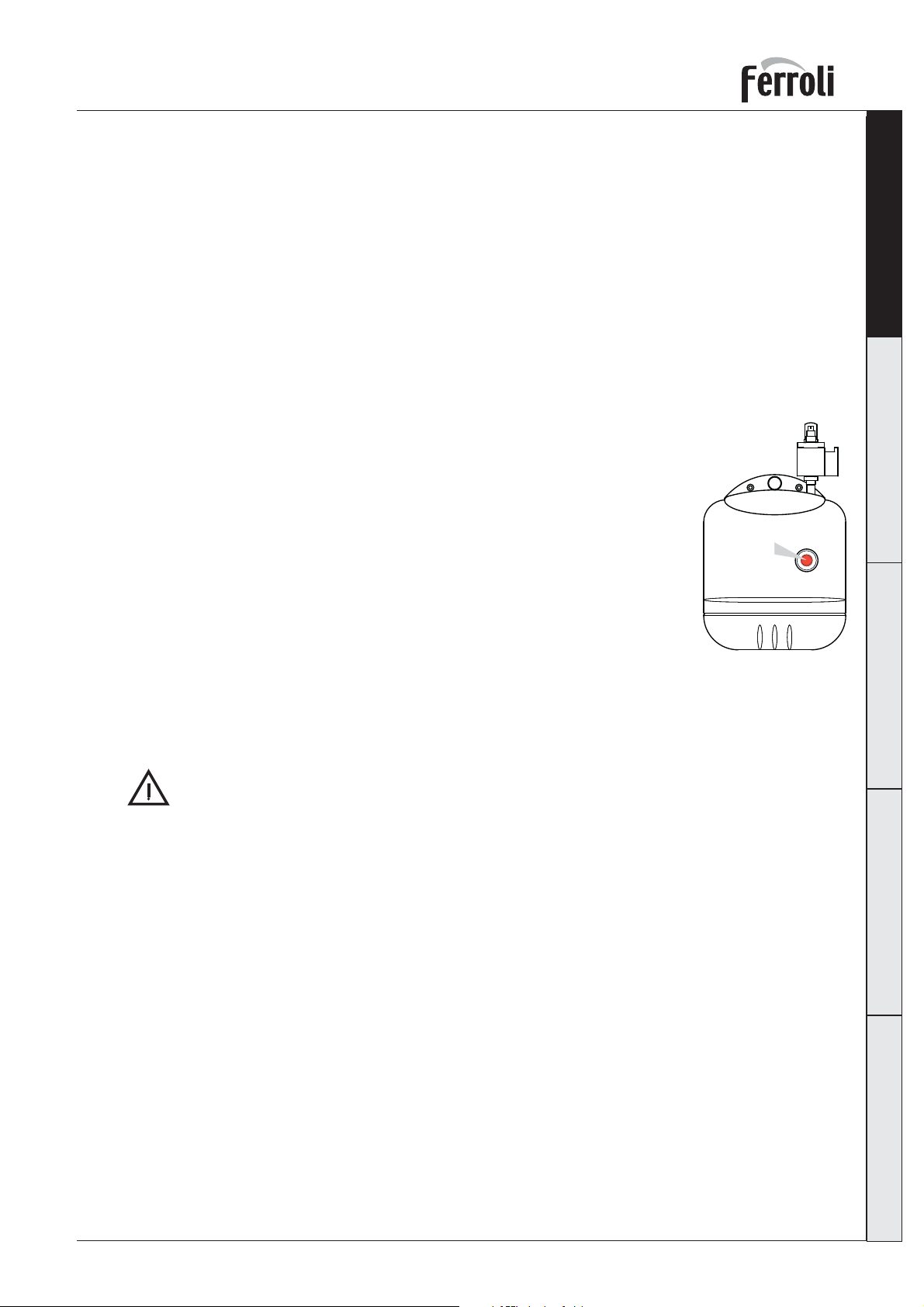
Il funzionamento del bruciatore, una volta installato e re go la to cor ret ta men te, è
completamente au to ma ti co e non richiede di fatto alcun co man do da parte dell’utente. In caso di mancanza di combustibile o anomalie il bru cia to re si arresta e
va in blocco (spia rossa sul pulsante di sblocco accesa). Si consiglia di provvedere
al rifornimento del com bu sti bi le prima del suo totale esaurimento per evitare
aspirazione di aria (fun zio na men to ir re go la re del bruciatore) o il disinnesco della
pompa (necessità di far intervenire il servizio assistenza).
Se la cisterna di combustibile è all’esterno, in zone dove la temperatura scende al
di sotto di -10 °C è necessario prov ve de re alla protezione di cisterna e tubazioni
di alimentazione ed usare gasolio in ver na le o ag giun ge re un additivo specifico
contro il gelo.
Fare attenzione che il locale in cui è installato il bruciatore, oltre che privo di oggetti
o materiali in fiam ma bi li, gas corrosivi o sostanze volatili, non sia polveroso. La polvere, infatti, ri chia ma ta
dal ventilatore, aderisce alle pale della girante e ne riduce la portata d’aria oppure causa l’ostruzione
del disco di stabilità fiamma pregiudicandone l’efficienza.
Pul san te
di riarmo
Italiano English Français Deutsch Español
fig. 1
Non permettere che il bruciatore sia manomesso da persone inesperte o da bambini.
1.3 Manutenzione
Provvedere pe rio di ca men te, almeno una volta all’anno, alla manutenzione del bruciatore. La ma nu ten zio ne
deve essere fatta da personale qualificato e di sicura qualificazione se con do le indicazioni contenute
nel capitolo 3.
1.4 Anomalie
Se il bruciatore non si avvia e la spia rossa sul pulsante di sblocco non è accesa, controllare che vi sia
alimentazione elettrica, che I’ interruttore dell’impianto termico sia inserito, i fusibili siano efficienti e vi
sia richiesta di calore in caldaia.
Se il bruciatore è fermo in blocco (spia rossa sul pulsante di sblocco accesa), attendere 15 secondi e
premere il pulsante di sblocco per ripristinare il funzionamento. Il bruciatore farà un ten ta ti vo di accensione. Se ritorna in blocco, controllare che vi sia combustibile in cisterna e che le valvole manuali poste
sul condotto di alimentazione del gasolio siano aperte. Se queste verifiche non danno esito favorevole,
contattare il servizio assistenza.
Se durante il funzionamento del bruciatore intervengono dei rumori anomali contattare il servizio assistenza.
Cod. 35445523 - 02/2007 (Rev. 00)
3
Page 4
2. INSTALLAZIONE
2.1 Disposizioni generali
ItalianoEnglishFrançaisDeutschEspañol
Questo apparecchio deve essere destinato solo all’uso per il quale è stato espressamente previsto. Questo apparecchio può essere applicato, compatibilmente alle sue caratteristiche e prestazioni ed alla sua
potenzialità termica, a caldaie ad acqua, a vapore, ad olio diatermico, e su altre utenze espres sa men te
previste dal relativo costruttore. Ogni altro uso deve considerarsi improprio e quindi pericoloso.
Non è consentito né aprire o manomettere i componenti dell’apparecchio, ad esclusione delle sole parti
previste nella manutenzione, né è consentito modificare l’apparecchio per alterarne le prestazioni o la
destinazione d’uso.
Se il bruciatore viene completato con optionals, kits o accessori si dovranno utilizzare solo prodotti
originali.
L’INSTALLAZIONE E LA TARATURA DEL BRUCIATORE DEVE ESSERE EFFETTUATA SOL TAN TO
DA PERSONALE SPECIALIZZATO E DI SICURA QUALIFICAZIONE, OT TEM PE RAN DO A
TUT TE LE ISTRU ZIO NI RIPORTATE NEL PRESENTE MANUALE TECNICO, ALLE DI SPO SI ZIO NI DI LEGGE VIGENTI, ALLE PRESCRIZIONI DI NORME NAZIONALI ED EVEN TUA LI
NORMATIVE LOCALI E SECONDO LE REGOLE DELLA BUONA TECNICA.
SUN G10 2S
2.2 Installazione in caldaia
Luogo di installazione
II locale entro il quale caldaia e bruciatore sono installati deve avere le aperture verso l’esterno se con do
quanto prescritto dalle norme vigenti. Se nello stesso locale vi sono più bruciatori o aspiratori che possono funzionare assieme, le aperture di aereazione devono essere dimensionate per il fun zio na men to
contemporaneo di tutti gli apparecchi.
Il luogo di installazione deve essere privo di oggetti o materiali infiammabili, gas corrosivi polveri o sostanze volatili che, richiamate dal ventilatore possano ostruire i condotti interni del bruciatore o la testa
di combustione. L’ambiente deve essere asciutto e non esposto a pioggia, neve o gelo.
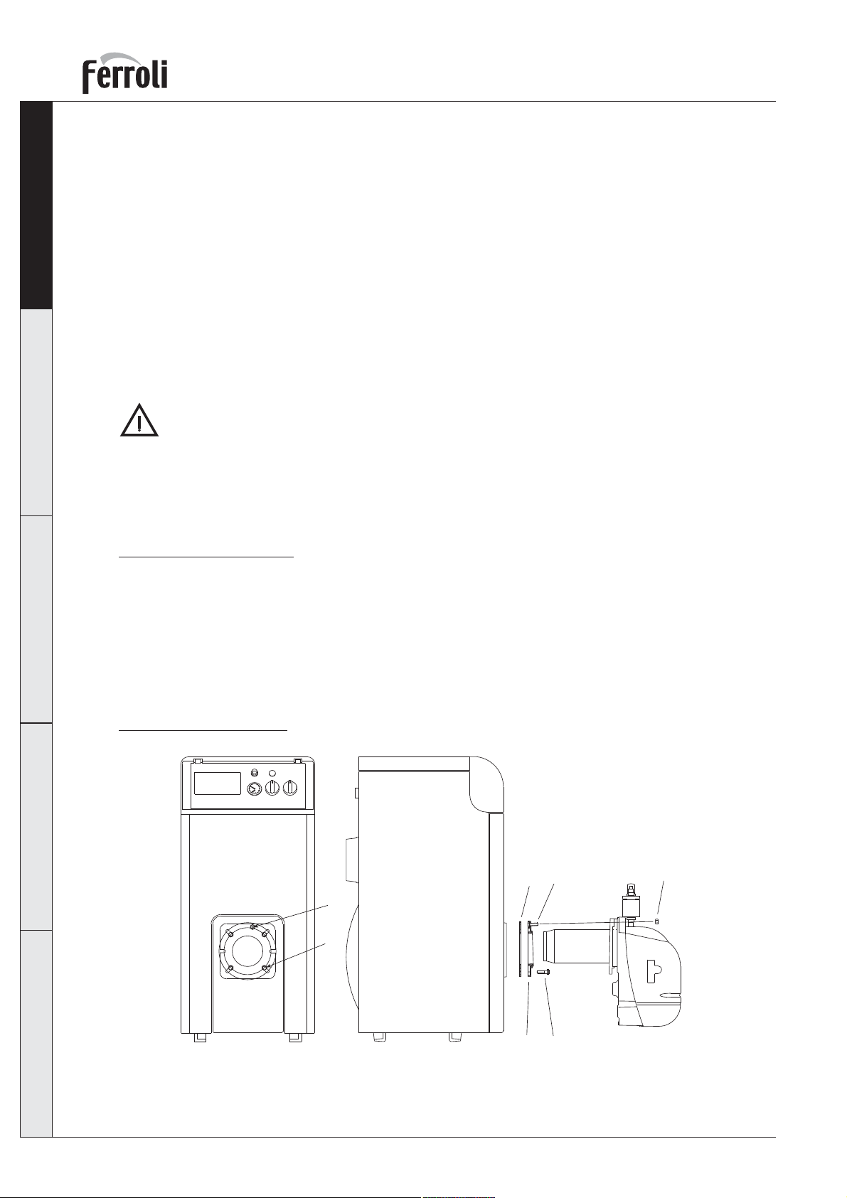
Fissaggio alla caldaia
2
1
4
4
5
fig. 2
1) Infilare la vite 2 (M8x40) nella flangia 3.
2) Fissare la flangia 3 alla caldaia con le viti 5 (Nr. 4 M8x20) interponendo la guarnizione iso lan te 1.
3) Infilare il bruciatore nella flangia caldaia e fissarlo alla vite 2 con il dado 4.
4
Cod. 35445523 - 02/2007 (Rev. 00)
5
3
Page 5
SUN G10 2S
2.3 Alimentazione combustibile
Disposizioni generali
Il bruciatore deve essere alimentato dal tipo di combustibile per il quale è predisposto, come indicato
sulla targa dell’apparecchio e nella tabella dati tecnici al cap. 4.3 di questo manuale.
II condotto di alimentazione del combustibile al bruciatore deve essere a perfetta tenuta per evitare
ingressi d’aria in pompa, deve essere dotato di un filtro sull’alimentazione a monte del bruciatore e
di tutti i dispositivi di sicurezza e controllo prescritti dalle norme vigenti. All’interno del condotto non
devono essere presenti impurità o residui di lavorazione: effettuare una pulizia dei condotti prima della
messa in opera.
Accertarsi inoltre, prima di mettere in funzione il bruciatore, che il tubo di ritorno del combustibile non
abbia occlusioni. Una eccessiva contropressione provocherebbe la rottura dell’organo di tenuta della
pompa.
La cisterna deve essere posizionata nel rispetto delle norme vigenti, e deve essere realizzata in modo
da evitare che acqua o impurità possano penetrarvi. Prima di immettervi il combustibile, deve essere
eseguita una accurata pulizia della cisterna.
Cisterna e condotto di alimentazione devono essere protetti dal gelo.
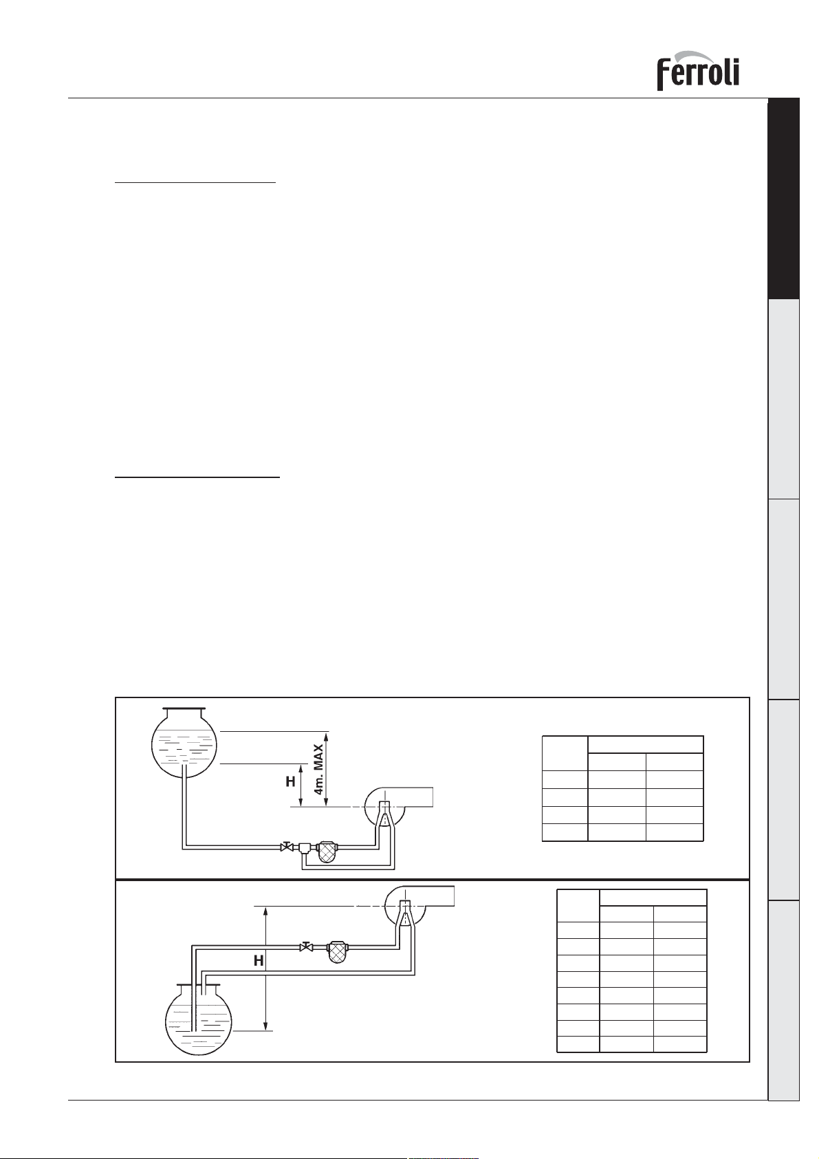
Circuito combustibile
Il bruciatore è dotato di pompa autoaspirante ed è in grado di alimentarsi autonomamente, entro i limiti
riportati di seguito. Per l’alimentazione del combustibile, i circuiti idraulici possono essere suddivisi in 4
tipologie, come riportato nelle figure seguenti:
A Alimentazione per caduta
B Alimentazione per aspirazione
C Alimentazione a sifone
D Alimentazione ad anello
Ad ogni tipologia di impianto è associata una tabella per il dimensionamento del condotto di ali men ta zio ne
in rapporto alla lunghezza (L) del tubo di aspirazione, e al dislivello (H) della cisterna. Non superare le
quote MAX riportate nelle figure per non sollecitare eccessivamente gli organi di tenuta della pompa.
Italiano English Français Deutsch Español
A
fig. 3a
B
fig. 3b
H
(m)
Øi 8 mm. Øi 10 mm.
0.5
1.0
1.5
2.0
10
20
40
60
H
(m)
Øi 8 mm. Øi 10 mm.
0.0
0.5
1.0
1.5
2.0
2.5
3.0
3.5
L (m)
20
40
80
100
L (m)
25 60
21
18
15
12
10
8
6
50
44
38
32
26
20
16
Cod. 35445523 - 02/2007 (Rev. 00)
5
Page 6
SUN G10 2S
ItalianoEnglishFrançaisDeutschEspañol
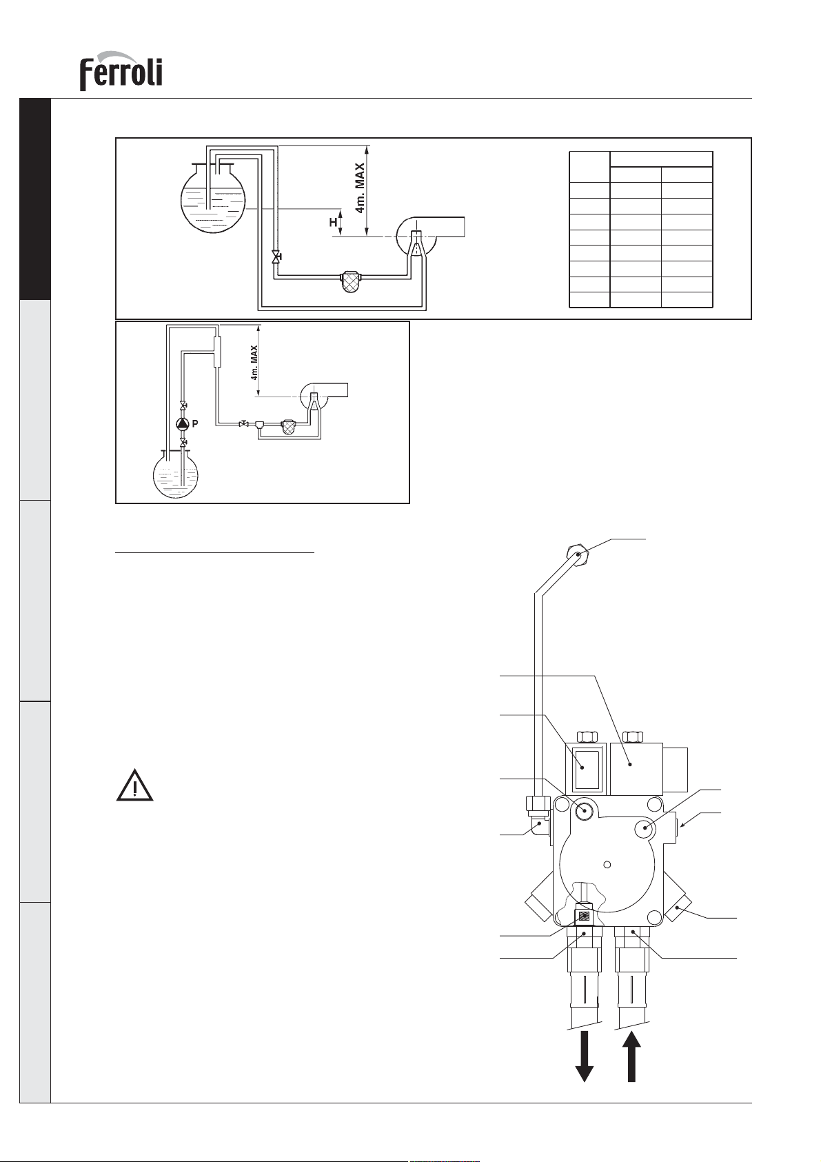
C
fig. 3c
D
Nota: per ogni curva o saracinesca som ma re alla lun-
ghez za della tubazione 0,25 metri (per di te di
carico).
L Lunghezza totale del tubo di aspirazione com pre si
i tratti ver ti ca li
H Differenza di livello
Øi Diametro interno della tubazione
fig. 3d
Collegamento alla pompa
Il bruciatore esce dalla fabbrica con il bypass interno alla
pompa chiuso, ovvero il bruciatore è pre di spo sto per col le ga men to bitubo. Togliere i tappi e collegare i due flessibili alla
pompa in aspirazione (1) e ritorno (2) come indicato in figura
4, avendo cura di non sottoporre a torsione i flessibili stessi
e di posizionarli in modo che non possano essere calpestati
o venire in contatto con parti calde della caldaia.
Volendo utilizzare il bypass interno alla pompa per col le ga men ti monotubo, è necessario togliere la vite di bypass (7)
e tappare il raccordo di ritorno (2) sulla pompa, collegando
il solo flessibile di aspi ra zio ne al raccordo (1).
P Pompa ausiliaria
(m)
0.0
0.5
1.0
1.5
2.0
2.5
3.0
3.5
H
L (m)
Øi 8 mm. Øi 10 mm.
25 60
21
18
15
12
10
8
6
50
44
38
32
26
20
16
11
8
9
Se la pompa viene fatta funzionare con ritorno
chiu so e vite di bypass inserita si dan neg gia
im me dia ta men te.
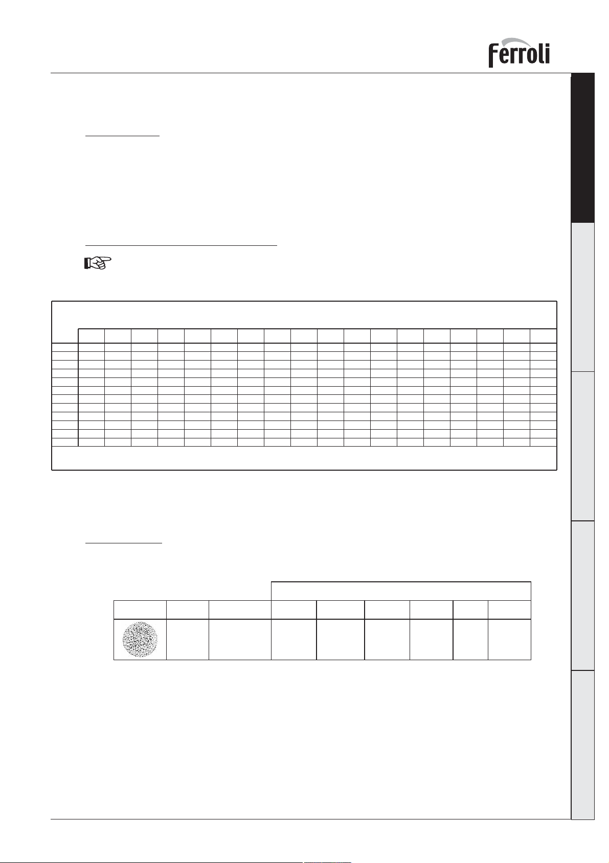
Legenda
1 Aspirazione
2 Ritorno con grano di by-pass interno
3 Mandata all’ugello
4 Regolazione pressione pompa 1° stadio
5 Attacchi manometro
6 Attacco vacuometro
7 Regolazione pressione pompa 2° stadio
8 Bobina 2° stadio
9 Bobina 1° stadio
10 Grano di by-pass
11 Ugello
6
Cod. 35445523 - 02/2007 (Rev. 00)
fig 4
5
3
10
2
6
4
7
1
Page 7
SUN G10 2S
2.4 Ugello ed elettrodi
Scelta ugello
Determinare la por ta ta com bu sti bi le richiesta, in base alla po ten za del fo co la re della caldaia ed al potere
calorifico inferiore (Hi) del combustibile utilizzato (rif. tabella dati tecnici cap. 4). In base alla portata
calcolata, ricavare dalla tabella sottostante, in funzione della pres sio ne pom pa, la gran dez za (in GPH)
dell’ugello più idonea. Nella tabella sono evidenziati in neretto i valori più idonei per il funzionamento
del bruciatore. Nel caso di bruciatori con il preriscaldatore i valore di portata effettiva sono inferiore di
circa il 10% rispetto ai valori riportati in tabella.
Tabella portata ugelli per gasolio
I valori sottoriportati sono indicativi poiché bi so gna tener presente che le portate degli ugel li
possono variare del ± 5%.
Pressione pompa bar
Ugello
8 9 10111213141516171819202122
GPH
0,85
2,89
3,05
3,23
3,39
3,54
3,68
3,82
3,96
4,09
4,21
1,00
1,10
1,20
1,25
1,35
1,50
1,65
1,75
2,00
2,25
3,40
3,74
4,08
4,25
4,59
5,10
5,61
5,95
6,80
7,65
3,61
3,97
4,33
4,50
4,87
5,41
5,95
6,31
7,21
8,15
3,80
4,18
4,56
4,75
5,13
5,70
6,27
6,65
7,60
8,55
3,99
4,38
4,78
5,00
5,38
5,90
6,58
6,98
7,97
8,97
4,16
4,58
5,00
5,20
5,62
6,24
6,87
7,29
8,33
9,37
4,33
4,77
5,20
5,40
5,85
6,50
7,15
7,58
8,67
9,75
4,50
4,95
5,40
5,60
6,07
6,75
7,42
7,87
8,99
10,12
4,65
5,12
5,59
5,80
6,28
6,98
7,68
8,15
9,31
10,47
4,81
5,29
5,77
6,00
6,49
7,21
7,93
8,41
9,61
10,85
4,96
5,45
5,95
6,20
6,69
7,43
8,18
8,67
9,91
11,15
4,33
5,10
5,61
6,12
6,35
6,88
7,65
8,41
8,92
10,20
11,47
4,45
5,24
5,76
6,29
6,55
7,07
7,86
8,64
9,17
10,48
11,79
4,57
5,37
5,91
6,45
6,70
7,26
8,06
8,87
9,41
10,75
12,09
4,68
5,51
6,06
6,61
6,85
7,44
8,26
9,09
9,64
11,01
12,39
4,79
5,64
6,20
6,76
7,05
7,61
8,46
9,30
9,86
11,27
12,68
23 24 25
4,90
5,76
6,34
6,92
7,20
7,78
8,65
9,30
9,86
11,27
12,68
5,00
5,89
6,48
7,07
7,35
7,95
8,83
9,30
9,86
11,27
12,68
Italiano English Français Deutsch Español
5,11
6,01
6,61
7,21
7,50
8,11
9,01
9,30
9,86
11,27
12,68
Portata alluscita dellugello in kg/h
Tabella spray
Gli ugelli sono disponibili con diversi spray, identificati da una o più lettere a seconda del costruttore.
Si riportano in tabella i tipi di spray più indicati per il bruciatore.
Tipo di ugello
ES
Fluidics
SF - S
SPRAY Angolo
60°
Tipo di cono
Pieno
Delavan
B
Monarch
AR
Danfoss
S
Steinen
S - SS
Hago
Cod. 35445523 - 02/2007 (Rev. 00)
7
Page 8
ItalianoEnglishFrançaisDeutschEspañol
SUN G10 2S
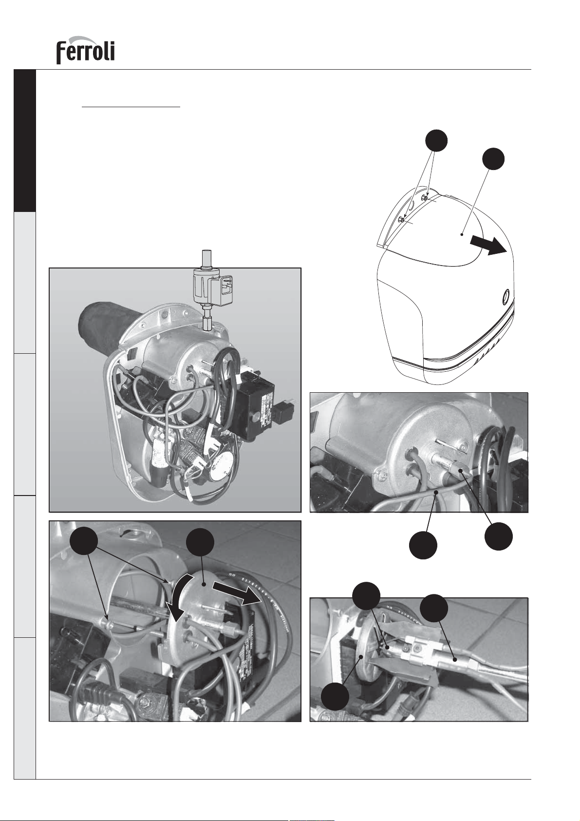
Montaggio ugello
Una volta determinato l’ugello corretto da utilizzare, pro ce de re come segue per il montaggio:
1 Svitare le viti “A”.
2 Togliere il co fa no “B”
3 Svitare per mez zo di una chiave il raccordo “C”
4 Estrarre dal raccordo il tubetto di rame “D”
5 Svitare leg ger men te le viti “E”
6 Ruotare ed estrar re il grupppo testa-portaugello “F”
7 Sfilare il portaugello “G” dalla testa di combusione “H”
8 Per mezzo di una chiave svitare l’ugello “I”
A
B
E
F
D
C
I
G
H
fig. 5
8
Cod. 35445523 - 02/2007 (Rev. 00)
Page 9
SUN G10 2S
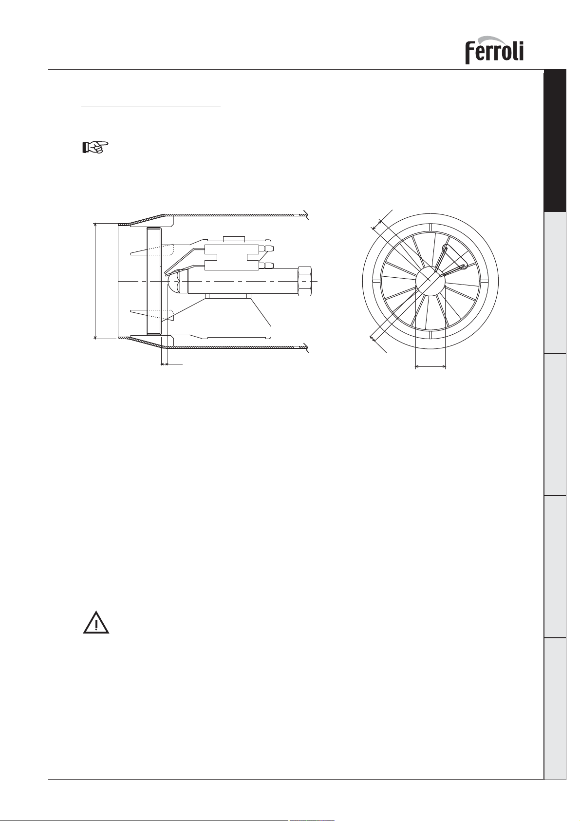
Posizionamento elettrodi
Dopo avere montato l'ugello, ve ri fi ca re il corretto posizionamento di elet tro di e deflettore, secondo le
quote sottoindicate.
E' opportuno ese gui re una ve ri fi ca del le quo te dopo ogni in ter ven to sulla testa.
Ø80
Italiano English Français Deutsch Español
6,5
3,5
5
fig. 6
Ø22
2.5 Collegamenti elettrici
Il bruciatore è dotato di 2 prese multipolari per gli allacciamenti elettrici; far riferimento allo sche ma
elet tri co nel capitolo “4 Caratteristiche e dati tecnici” per le connessioni. I collegamenti da effettuare
a cura dell’installatore sono:
• linea di alimentazione
• linea dei termostati
• eventuale lampada di blocco e/o contaore
La lunghezza dei cavi di collegamento deve permettere l’apertura del bruciatore ed eventualmente del
portellone della caldaia. In caso di guasto al cavo di alimentazione del bruciatore, la sua sostituzione va
fatta solo da persona abilitata.
Il bruciatore va collegata ad una linea elettrica monofase, 230 Volt-50 Hz.
Far verificare da per so na le professionalmente qua li fi ca to l’ef fi cien za e l’ade gua tez za del l’im -
pian to di terra, il costruttore non è responsabile per even tua li danni causati dalla man can za
di messa a terra dell’impianto. Far verificare inoltre che l’impianto elettrico sia adeguato alla
po ten za massima assorbita dall’apparecchio, indicata in targhetta dati caldaia.
E’ importante rispettare le polarità (LINEA: cavo marrone / NEUTRO: cavo blu / TERRA :
cavo giallo-verde) negli allacciamenti alla linea elettrica.
Cod. 35445523 - 02/2007 (Rev. 00)
9
Page 10
3. SERVIZIO E MANUTENZIONE
Tutte le operazioni di regolazione, messa in servizio e manutenzione devono essere effettuate da Per-
ItalianoEnglishFrançaisDeutschEspañol
so na le Qualificato e di sicura qualificazione, in conformità alle norme vigenti. Il personale della nostra
organizzazione di vendita e del Servizio Tecnico As si sten za Clienti di Zona è a vostra disposizione per
ogni ul te rio re informazione.
FERROLI S.p.A. declina ogni responsabilità per danni a cose e/o persone derivanti dalla ma no mis sio ne
del l’ap pa rec chio da parte di per so ne non qualificate e non au to riz za te.
3.1 Regolazioni
Regolazione testa e ser ran da aria
La regolazione della testa di pen de dalla portata del bru cia to re
e si ese gue ruotando in senso orario o antiorario la vite di re go la zio ne “B” fino a che la tacca incisa sull'asta "A" coin ci da
con l'indice.
Si modifica così la posizione del de flet to re rispetto al boccaglio
e di con se guen za il pas sag gio dell'aria.
SUN G10 2S
A
B
Per limitare le dispersioni al camino a caldaia spenta, il
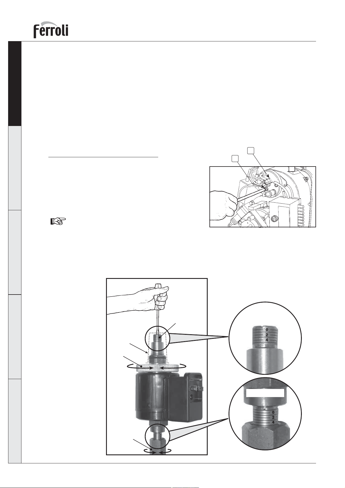
bruciatore è dotato di una serranda aria a gravità che si
chiude automaticamente all’arresto del bruciatore.
1° stadio: allentare il bullone “1” e ruotare la ghiera “2” sino al valore desiderato. Stringere il bullone
“1”.
2° stadio: togliere il cappuccio “3” e con un cacciavite ruotare la vite “4” sino al valore desiderato.
Riposizionare il cappuccio.
fig. 7
2° Sta dio
4
3
2
10
1° Sta dio
1
fig. 8
Cod. 35445523 - 02/2007 (Rev. 00)
Page 11
SUN G10 2S
Per una regolazione preliminare di testa e serranda aria al momento dell’installazione (prima di ese gui re
la messa in servizio e conseguente taratura strumentale) utilizzare la tabella sottostante:
Italiano English Français Deutsch Español
Modello
caldaia
GN1 N 05
GN1 N 06
GN1 N 07
GN1 N 08
Prextherm RSW 92
Prextherm RSW 107
Portata
termica
44.2÷64.5
53.2÷77.5
62÷90.4
70.8÷103.3
64.3÷99.5
75÷116.3
Ugello
DANFOSS
GPH
Angolo
1.1
1.25
1.5
1.75
1.5
1.75
60°
60°
60°
60°
60°
60°
Pressione
pompa 1°
bar
9
9
9
9
10
9
Pressione
pompa 2°
bar
17
18
18
17
20
22
Regolazione
aria 1°
Tacca
1
1
3
3
3
4
Regolazione
aria 2°
Tacca
1
1
5
5
6
6
Regolazione
L
12
15
20
22
22
32
Regolazione pressione pompa
- La regolazione consigliata per il funzionamento in 1° stadio è di 8÷12 bar.
- La regolazione consigliata per il funzionamento in 2° stadio è di 16÷22 bar.
3.2 Messa in servizio
Verifiche da eseguire alla prima accensione, e dopo tutte le operazioni di manutenzione che abbiano comportato la disconnessione dagli impianti o un intervento su organi di sicurezza o parti del bru cia to re:
Prima di accendere il bruciatore,
• Controllare che il bruciatore sia fissato correttamente in caldaia con le tarature preliminari indicate
precedentemente.
• Accertarsi che caldaia ed impianto siano stati riempiti d’acqua od olio diatermico, che le valvole del
circuito idraulico siano aperte e che il condotto di evacuazione fumi sia libero e correttamente dimensionato.
• Verificare la chiusura della porta caldaia, in modo che la fiamma si generi solamente all’interno della
camera di combustione.
• Montare il manometro ed il vacuometro sulla pompa (da togliere dopo la messa in funzione).
• Aprire le saracinesche lungo la tubazione del gasolio, assicurandosi che vi sia combustibile in ci ster na
e che il tubo di ritorno non abbia occlusioni.
Attenzione: Un eventuale occlusione può pro vo ca re la rottura dell’organo di tenuta della pompa.
testa
Tacca
0
3
8
10
10
20
Accensione del bruciatore
• Fornire alimentazione elettrica, chiudendo l’interruttore generale a monte del bruciatore
• Chiudere la linea dei termostati (caldaia/ambiente)
• Sbloccare l’apparecchiatura (premendo il pulsante rosso)
• Inizia il funzionamento secondo il diagramma di fig. 9:
1 Il motore del bruciatore si mette in rotazione assieme alla pompa: il gasolio aspirato viene to tal men te
inviato verso il ritorno. Si attiva contemporaneamente anche il trasformatore d’ac cen sio ne.
2 Si effettuano le fasi di preventilazione del focolare, prelavaggio di una parte del circuito gasolio,
preaccensione, con scarica fra le punte degli elettrodi.
3 Alla fine del prelavaggio l’apparecchiatura apre la valvola elettromagnetica: il gasolio giunge all’ugel-
lo, dal quale esce polverizzato. Il contatto con la scarica fra gli elettrodi, determina la formazione
della fiamma. Contemporaneamente inizia il tempo di sicurezza entro il quale la fotoresistenza deve
rivelare presenza di fiamma.
4 Se la fotoresistenza non rivela presenza di fiamma il bruciatore va in blocco (la spia rossa si il lu mi na).
Attendere circa 15 s, sbloccare e ripetere il ciclo di accensione.
Cod. 35445523 - 02/2007 (Rev. 00)
11
Page 12
ItalianoEnglishFrançaisDeutschEspañol
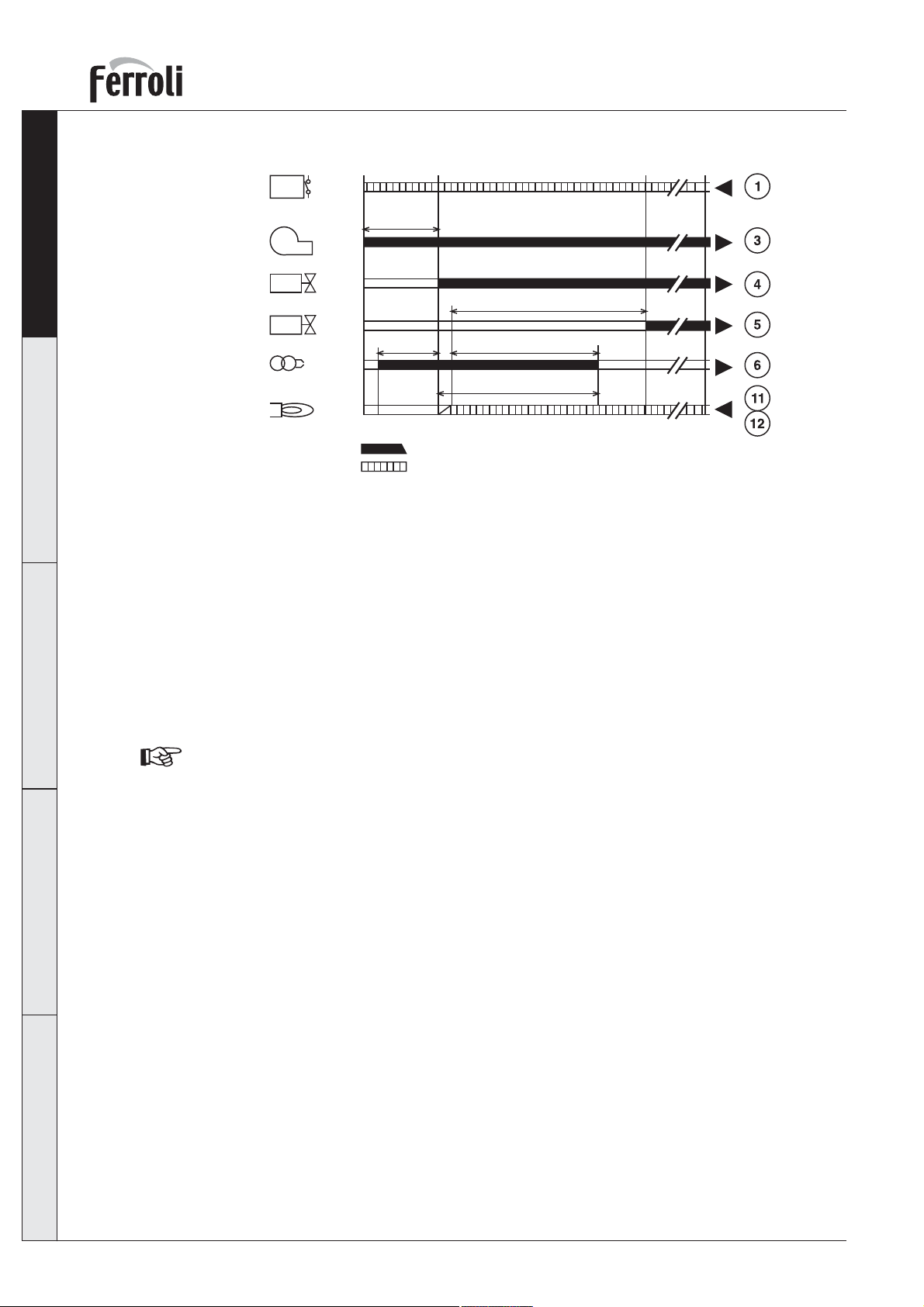
Termostati
Motore
Elettrovalvola
1° stadio
Elettrovalvola
2° stadio
Trasformatore
daccensione
Fotoresistenza
Legenda
SUN G10 2S
AB CD
R
W
SB
t1
M
BV1
t4
BV2
t3
Z
FS
Segnale in uscita
Richiesta di segnale in ingresso
fig. 9
t3n
TSA
A Inizio della messa in servizio per bruciatori senza preriscaldatore
B Momento accensione fiamma
C Funzionamento
D Arresto per regolazione R
t1 Tempo di preventilazione
t3 Tempo di preaccensione
t3n Tempo dopo l’accensione
t4 Intevallo tra segnalazione fiamma e alimentazione BV2
TSA Tempo di sicurezza alla partenza
In particolare con impianti monotubo, se la tubazione di aspirazione del combustibile è ini zial men te
vuota, perché la pompa del combustibile possa innescarsi, è necessario permettere lo sfiato
dell’aria contenuta nel tubo stesso. Si consiglia , prima di accendere il bruciatore, di allentare la
vite di collegamento al manometro sulla pompa ed eseguire poi il ciclo di accensione. Quando
il gasolio fuoriesce dalla vite, la pompa è innescata. Spegnere il bruciatore e riavvitare la vite.
12
Cod. 35445523 - 02/2007 (Rev. 00)
Page 13

SUN G10 2S
Verifiche e regolazioni durante il funzionamento
• Collegare un analizzatore di combustione all’uscita della caldaia e lasciare funzionare il bruciatore a
pieno regime per 10 minuti; verificare nel frattempo la funzionalità del condotto di evacuazione dei
fumi.
• Regolare lentamente la serranda aria fino ad ottenere il valore voluto di eccesso d’aria per il fun zio na men to, verificando tramite l’analizzatore di combustione il tenore di O
nei fumi non dovrebbe essere inferiore a 2,5% (rischio di combustione inquinante) e non dovrebbe
su pe ra re il 5% (rischio di difficoltà di accensione e produzione di fuliggine).
• Eseguire di seguito alcune accensioni. In caso di pulsazioni fiamma o difficoltà di accensione, agire
anche sulla regolazione della testa, sempre verificando tramite l’analizzatore di combustione il tenore
nei fumi.
di O
• Accertarsi che la pressione in camera di combustione sia quella indicata dal costruttore della cal-
• Eseguire l’analisi completa dei fumi di combustione e verificare il rispetto dei limiti imposti dalle norme
2
daia
vigenti.
nei fumi. Il tenore di O2
2
3.3 Manutenzione
Il bruciatore richiede una manutenzione periodica, con cadenza almeno annuale, che deve essere eseguita da personale abilitato.
Le operazioni basilari da effettuare sono:
• controllo e pulizia delle parti interne del bruciatore, di cisterna e caldaia come indicato nei paragrafi
successivi;
• analisi completa della combustione (dopo funzionamento a regime per almeno 10 minuti) e verifica
delle corrette tarature;
Italiano English Français Deutsch Español
Apertura cofano e smontaggio del
bru cia to re
Prima di effettuare qualsiasi
ope ra zio ne di pulizia o con trol lo al l’in ter no del bru cia to re, togliere l’ali men ta zio ne
elettrica al bru cia to re agen do
sull’interruttore ge ne ra le del l’im pian to e chiu de re l’ali men ta zio ne del com bu sti bi le.
• Per l’apertura, svitare le viti (A) e to glie re il cofano (B). I componenti in ter ni,
pom pa, motore, serranda, ecc. sono
di ret ta men te ac ces si bi li.
• Per lo smontaggio, svitare il dado (C),
estrarre il bruciatore dalla caldaia e po si zio nar lo in modo da accedere a testa,
elet tro di ed ugello.
fig 10
C
A
B
Verifiche su parti e componenti
Pompa
La pressione deve essere stabile al valore regolato in fase di installazione.
Non si deve avvertire rumorosità.
Nel caso di pressione instabile o pompa rumorosa, scollegare il tubo flessibile dal filtro di linea ed aspi-
rare il combustibile da un serbatoio posto vicino al bruciatore. In questo modo è possibile in di vi dua re
se causa delle anomalie è il condotto di aspirazione o la pompa.
Cod. 35445523 - 02/2007 (Rev. 00)
13
Page 14

ItalianoEnglishFrançaisDeutschEspañol
SUN G10 2S
Filtri
Controllare e pulire o sostituire se necessario i filtri di linea, in pompa, all’ugello.
Se all’interno del filtro pompa si notano ruggine o altre impurità, aspirare dal fondo della cisterna con
una pompa separata acqua ed altre impurità eventualmente depositatesi.
Ventilatore
Verificare che all’interno del ventilatore e sulle pale della girante non vi sia accumulo di polvere: riduce
la portata d’aria e causa, conseguentemente, combustione inquinante.
Testa di combustione
Verificare che tutte le parti della testa di combustione siano integre, non deformate dall’alta tem pe ra tu ra,
prive di impurità provenienti dall’ambiente e correttamente posizionate.
Ugelli
Evitare di pulire il foro dell’ugello al fine di non danneggiarli
Sostituire l’ugello ogni 2-3 anni, o quando necessario. Il cambio dell’ugello richiede un controllo della
combustione.
Fotoresistenza
Pulire il vetrino da polvere eventuale. La fotoresistenza è inserita in sede a pressione, per estrarre tirarla
verso l’esterno.
Tubi flessibili
Controllare che il loro stato sia buono, che non siano stati calpestati o deformati.
Cisterna
Ogni 5 anni, circa, aspirare l’acqua dal fondo della cisterna con una pompa separata.
3.4 Risoluzione dei problemi
Problema Possibile causa/ Soluzione consigliata
Il bruciatore non parte Mancanza energia elettrica / Chiudere interruttori controllare fusibili
Apparecchiatura in blocco / Sbloccare apparecchiatura
Apparecchiatura elettrica difettosa / Sostituire
Pompa bloccata / Sostituire
Motore elettrico difettoso / Sostituire
Il bruciatore durante la Collegamenti elettrici errati / Controllare
preventilazione si Fotoresistenza in cortocircuito / Sostituire fotoresistenza
arresta in blocco Luce estranea investe la fotoresistenza / Eliminare fonte di luce
Apparecchiatura elet tri ca difettosa / Sostituire
Valvola gasolio difettosa / Sostituire
Il bruciatore esegue Manca il combustibile in cisterna, o vi è acqua sul fondo / Rifornire combustibile
preventilazione e ciclo o aspirare l’acqua
di accensione ma non Valvole alimentazione linea gasolio chiuse / Aprire
c’è innesco fiamma e Filtri sporchi (linea – pompa - ugello) / Pulire
il bruciatore va Pompa disinnescata / Innescare e cercare causa disinnesco
in blocco. Elettrodi d’accensione mal regolati, o sporchi / Regolarli o pulirli
Ugello otturato, sporco o deformato / Sostituire
Regolazioni testa e serranda non adatte / Regolare
Elettrodi difettosi o a massa / Sostituire
Trasformatore d’accensione difettoso / Sostituire
Cavi elettrodi difettosi o a massa / Sostituire
Cavi elettrodi deformati da alta temperatura / Sostituire e proteggere
14
Cod. 35445523 - 02/2007 (Rev. 00)
Page 15

SUN G10 2S
Collegamenti elettrici valvola o trasformatore errati / Controllare
Apparecchiatura difettosa / Sostituire
Giunto motore-pompa rotto / Sostituire
Aspirazione pompa collegata al tubo di ritorno / Correggere collegamento
La fiamma si accende Fotoresistenza difettosa / Sostituire
regolarmente ma Fotoresistenza sporca / Pulire fotoresistenza
il bruciatore va in Apparecchiatura difettosa / Sostituire
blocco al termine del
tempo di sicurezza
Accensione con Testa mal regolata / Regolare
pulsazioni o con Elettrodi d’accensione mal regolati o sporchi / Regolare o pulire
distacco fiamma, Serranda ventilatore mal regolata, troppa aria / Regolare
accensione ritardata Ugello non adatto al bruciatore o alla caldaia / Vedere tabella ugelli
Ugello difettoso / Sostituire
Pressione pompa non adatta / Regolare tra min 10 e max 14 bar
Pompa rumorosa, Ingresso aria nella tubazione di aspirazione / Bloccare i raccordi
pressione pulsante Dislivello bruciatore cisterna troppo elevato / Alimentare bruciatore con circuito ad anello
Diametro tubazione troppo piccolo / Aumentare diametro
Filtri in aspirazione sporchi / Pulire
Valvole alimentazione linea gasolio chiuse / Aprire
Solidificazione paraffina per bassa temperatura / Aggiungere additivo nel gasolio
Italiano English Français Deutsch Español
e pompa ausiliaria
La pompa si disinnesca Tubo di ritorno non immerso nel combustibile / Portarlo alla stessa altezza del tubo di
dopo una sosta aspirazione
prolungata Ingresso d’aria nella tubazione di aspirazione / Bloccare i raccordi
Pompa con perdita Perdita dall’organo di tenuta / Sostituire pompa
di gasolio
Alimentazione Impianto dì alimentazione o pompa ostruiti difettosi / Alimentare il bruciatore da un
combustibile irregolare serbatoio posto vicino al bruciatore per individuare se il problema dipende da pompa o
impianto
Fuliggine Aria insufficiente / Regolare testa e serranda ventilatore
Bacharach scuro Ugello sporco o usurato / Sostituire
Filtro ugello sporco / Pulire o sostituire
Pressione pompa errata / Regolare
Disco di stabilità fiamma sporco, allentato o deformato / Pulire, bloccare o sostituire
Ventilazione locale caldaia insufficiente / Verificare aperture di ventilazione locale, pulirle
o aumentarle
Bacharach giallo Eccesso aria / Regolare testa e serranda ventilatore.
Testa di combustione Regolazione testa errata o aria insufficiente / Regolare testa, aprire serranda aria
sporca Ugello o filtro ugello sporco / Sostituire
Angolo o portata ugello non adatti / Sostituire
Ugello allentato / Bloccare
Impurità dall’ambiente sul disco di stabilità / Pulire
Cod. 35445523 - 02/2007 (Rev. 00)
15
Page 16

SUN G10 2S
4. CARATTERISTICHE E DATI TECNICI
4.1 Dimensioni
ItalianoEnglishFrançaisDeutschEspañol
197 210
125
Ø100
421
296
408
Ø 170
Ø 140
238
Ø101
263
fig. 11
4.2 Vista generale e componenti principali
13
16
8
17
3
4
Legenda
18
7
14
5
6
10
19
fig. 12
91211
1
2
15
1 Pompa gasolio
2 Motore
3 Valvola elettromagnetica
4 Corpo bruciatore
5 Pulsante di sblocco
6 Apparecchiatura
7 Fotoresistenza
8 Trasformatore d'accensione
9 Flangia attacco bruciatore
10 Linea ugello
16
11 Elettrodi di accensione
12 Boccaglio
13 Attuatore elettrico regolazione aria
14 Spina allacciamento elettrico
15 Ventola
16 Regolazione testa di com bu stio ne
17 Regolazione pressione pom pa
18 Presa di pressione
19 Spina 2° stadio
Cod. 35445523 - 02/2007 (Rev. 00)
Page 17

SUN G10 2S
4.3 Tabella dati tecnici
Bruciatore SUN G10 2S
Potenza
Portata
Combustibile
Funzionamento
Alimentazione elettrica 220-240V 50HZ
Motore W110
Potenza Assorbita W 160
Grado di protezione IP 40
4.4 Campo di lavoro
1.2
0.8
0.6
0.4
0.2
Pressione (mbar)
-0.2
fig. 13
4.5 Schema elettrico
1° stadio
kW 47,5
kg/h 4
Hi 11,86
Gasolio
1
0
40.0 50.0 60.0 70.0 80.0 90.0 100.0 110.0 120.0
Potenza (kW)
kWh/kg
Densità 0,82-0,85
Viscosità a 20°C 1,5° E
kg/dm
V/Hz
Min
3
Intermittente
2° stadio
MaxMin
118,663,2
bistadio
Italiano English Français Deutsch Español
105,3
Legenda
BZ1 Contaore 1° stadio
BZ2 Contaore 2° stadio
F Fusibile
FR Fotoresistenza
IG Interruttore ge ne ra le
LS Lampada si cu rez za
MB Motore bruciatore
PB Presa bruciatore
SC Spina
TR1 Ter mo sta to caldaia - am bien te
TR Trasformatore d'accensione
TR2 Termostato 2° stadio
TS Termostato sicurezza
VE1 Valvola elettromagnetica 1° stadio
VE2 Valvola elettromagnetica 2° stadio
R Relé
AT Attuatore aria
Cod. 35445523 - 02/2007 (Rev. 00)
fig. 14
17
Page 18

Certificato di Garanzia
Certificato di Garanzia
La presente garanzia convenzionale è valida per gli apparecchi destinati alla
commercializzazione, venduti ed installati sul solo territorio italiano
La Direttiva Europea 99/44/CE ha per oggetto taluni aspetti della vendita e delle garanzie dei beni di consumo e regolamenta
il rapporto tra venditore finale e consumatore. La direttiva in oggetto prevede che in caso di difetto di conformità del prodotto,
il consumatore ha diritto a rivalersi nei confronti del venditore finale per ottenerne il ripristino senza spese, per un periodo
di 24 mesi dalla data di acquisto.
Ferroli S.p.A., pur non essendo venditore finale nei confronti del consumatore, intende comunque supportare le responsabilità
del venditore finale con una propria Garanzia Convenzionale, fornita tramite la propria rete di assistenza tecnica autorizzata
alle condizioni riportate di seguito.
Oggetto della Garanzia e Durata
Con la presente garanzia convenzionale l'azienda produttrice garantisce da tutti i difetti di fabbricazione e di funzionamento
gli apparecchi venduti per 24 mesi dalla data di consegna, documentata attraverso regolare documento di acquisto, purché
avvenuta entro 3 anni dalla data di fabbricazione del prodotto. La messa in servizio del prodotto deve essere effettuata a
cura della società installatrice. Entro 30 giorni dalla messa in servizio il Cliente può richiedere ad un Centro di Assistenza
autorizzato il primo controllo gratuito. In questo caso, se il bruciatore è stato abbinato ad una caldaia Ferroli, sullo
scambiatore principale della caldaia viene esteso un ulteriore anno di garanzia (quindi 3 anni), sempre a decorrere
dalla data di consegna.
Modalità per far valere la presente Garanzia
In caso di guasto, il cliente deve richiedere entro il termine di decadenza di 30 giorni lintervento del Centro Assistenza di
zona, autorizzato Ferroli S.p.A.
I nominativi dei Centri Assistenza autorizzati sono reperibili:
attraverso il sito internet dellazienda costruttrice;
attraverso il numero verde 800-59-60-40.
I costi di intervento sono a carico dellazienda produttrice, fatte salve le esclusioni previste e riportate nella presente
Dichiarazione. Gli interventi in garanzia non modificano la data di decorrenza o la durata della stessa.
CERTIFICATO DI GARANZIA
Esclusioni
Sono escluse dalla presente garanzia i guasti e gli eventuali danni causati da:
trasporto non effettuato a cura dellazienda;
inosservanza delle istruzioni e delle avvertenze previste dallazienda produttrice e riportate sui manuali di utilizzo a corredo
del prodotto;
errata installazione o inosservanza delle prescrizioni di installazione, previste dallazienda produttrice e riportate sui
manuali di installazione a corredo del prodotto;
inosservanza di norme e/o disposizioni previste da leggi e/o regolamenti vigenti, in particolare per assenza o difetto di
manutenzione periodica;
anormalità o anomalie di qualsiasi genere nellalimentazione degli impianti idraulici, elettrici, di erogazione del combustibile,
di camini e/o scarichi;
inadeguati trattamenti dell'acqua di alimentazione, trattamenti disincrostanti erroneamente effettuati;
corrosioni causate da condensa o aggressività d'acqua;
gelo, correnti vaganti e/o effetti dannosi di scariche atmosferiche;
mancanza di dispositivi di protezione contro le scariche atmosferiche;
trascuratezza, incapacità d'uso, manomissioni effettuate da personale non autorizzato o interventi tecnici errati effettuati
sul prodotto da soggetti estranei alla rete di assistenza autorizzata Ferroli;
impiego di parti di ricambio non originali Ferroli;
manutenzione inadeguata o mancante;
parti soggette a normale usura di impiego (anodi, guarnizioni, manopole, lampade spia, ecc.);
cause di forza maggiore indipendenti dalla volontà e dal controllo dellazienda produttrice;
non rientrano nella garanzia le operazioni di pulizia e manutenzione ordinaria, né eventuali attività o operazioni per
accedere al prodotto (smontaggio mobili o coperture, allestimento ponteggi, ecc.).
Responsabilità
Il personale autorizzato dalla azienda produttrice interviene a titolo di assistenza tecnica nei confronti del Cliente; linstallatore
resta comunque lunico responsabile dellinstallazione che deve rispettare le prescrizioni di legge e le prescrizioni tecniche
riportate sui manuali di installazione a corredo del prodotto.
Le condizioni di garanzia convenzionale qui elencate sono le uniche offerte da Ferroli Spa. Nessun terzo è autorizzato a
modificare i termini della presente garanzia né a rilasciarne altri verbali o scritti.
Diritti di legge
La presente garanzia si aggiunge e non pregiudica i diritti dellacquirente previsti dalla direttiva 99/44/CEE e relativo
decreto nazionale di attuazione.
FERROLI S.p.A. - Via Ritonda 78/a - 37047 San Bonifacio (Verona) Italy - tel. +39.045.6139411 - fax. +39.045.6100933 - www.ferroli.it
Page 19

SUN G10 2S
• Carefully read the warnings in this instruction
booklet, as they provide important indications
on the safety of installation, operation and
maintenance.
• The instruction booklet is an integral and essential part of the product and must be carefully
kept by the user for fu tu re reference.
• The installation and maintenance operations
must be performed according to the standards
in force, the instructions of the manufacturer
and must be carried out by professionally
qualified personnel.
• Incorrect installation or poor maintenance may
cau se damage to people, animals or things. The
manufacturer declines all liability for damage
deriving from errors in the installation and
operation of the appliance, and in any case
from the failure to observe the instructions
provided by the manufacturer.
• Before performing any cleaning or maintenance
operations, disconnect the appliance from the
mains power supply using the system switch
and/or the corresponding on-off devices.
• In the event of faults and/or poor operation
of the appliance, it should be deactivated. Do
not attempt to repair the appliance. Contact
professionally qualified personnel only.
• After having removed the packaging, check
that the contents are intact.
• The parts of the packaging must not be left
within the reach of children, as they are potential
sources of danger.
Italiano English Français Deutsch Español
Certification
The CE Mark attests that Ferroli appliances conform to the requirements specified in the corresponding European directives.
In particular, this appliance conforms to the following EEC directives:
• Directive 92/42, Efficiency, accepted into Italian law by Presidential Decree no. 660, 15.11.96
• Directive 73/23, Low Voltage, (amended by no. 93/68)
• Directive 89/336, Electromagnetic Compatibility (amended by no. 93/68) accepted into Italian law
by Presidential Decree no. 615, 15/11/96
This symbol indicates “Warning” and is placed near all warnings regarding safety. Such
provisions must be strictly adhered to so as to avoid danger and damage to people, animals and things.
This symbol highlights a note or an important warning
1. Operating instructions ..........................................................................20
2. Installation ............................................................................................21
3. Service and maintenance ......................................................................27
4. Characteristics and technical specifications ..........................................33
Cod. 35445523 - 02/2007 (Rev. 00)
19
Page 20

1. OPERATING INSTRUCTIONS
1.1 Introduction
ItalianoEnglishFrançaisDeutschEspañol
Dear Customer,
Thank you for having chosen the SUN G10 2S, an advanced-concept FERROLI burner featuring cutting-
edge technology, high reliability and constructional quality.
The SUN G10 2S is an oil burner, whose compact dimensions and original design make it ideal for use
with most of the boilers currently present on the market. The attention paid to the design and industrial
production of the appliance has resulted in a product that is well-balanced and highly efficient, with very
low CO and NOx emissions and a very silent flame.
1.2 Operating instructions
The operation of the burner, once correctly installed and adjusted, is completely
automatic and does not require any intervention by the user. In the event of no fuel
or operating anomalies, the burner stops and shuts-down (the red light on the reset
button turns on). It is recommended to replete the supply of fuel before it runs out
completely, to avoid the inlet of air (irregular operation of the burner) or the loss of
prime of the pump (in which case the assistance of the service centre is required).
If the fuel tank is outside, in areas where the temperature falls below -10 °C, the
tank and fuel supply pipes must be adequately protected. Use winter oil or add a
specific anti-freeze.
Make sure that the room where the burner is installed is free of inflammable objects
or materials, corrosive gas or volatile substances, and is not dusty. Dust, in fact, is
sucked in by the fan and sticks to the blades of the rotor and reduces air flow, or
alternatively blocks the flame stability disk, compromising efficiency.
SUN G10 2S
Burner
reset
button
fig. 1
Do not allow the burner to be tampered with by inexpert persons or children.
1.3 Maintenance
Make sure that maintenance is performed on the burner periodically, at least once a year. The maintenance operations must be performed by qualified and specialist personnel according to the indications
contained in chapter 3.
1.4 Anomalies
If the burner does not ignite and the red light on the reset button is not on, check that there is electrical power, that the heating system switch is on, that the fuses are intact and that there is an effective
request for heat from the boiler.
If the burner is still off (red light on the reset button on), wait 15 seconds and press the reset button to
reset operation. The burner will attempt to ignite. If it shuts down again, check that there is fuel in the
tank and that the manual valves located on the oil supply pipe are open. If these checks do not resolve
the problem, contact the service centre.
If noise is produced during the operation of the burner, contact the service centre.
20
Cod. 35445523 - 02/2007 (Rev. 00)
Page 21

SUN G10 2S
2. INSTALLATION
2.1 general instructions
This appliance must only be used for the purposes it has been specifically designed for. This appliance
may be applied, according to its characteristics, performance and heating capacity, to water boilers,
steam boilers, diathermic oil boilers and other utilities, as expressly envisaged by the manufacturer of
such. All other uses are considered improper and thus dangerous.
The appliance may not be opened nor its components tampered with, except for the parts included in
the maintenance operations. The appliance may not be modified to alter its per for man ce or use.
If the burner is fitted with optional devices, kits or accessories, only original products should be used.
THE BURNER MUST ONLY BE INSTALLED AND ADJUSTED BY QUALIFIED AND SPECIALIST
PERSONNEL, IN COMPLETE COMPLIANCE WITH ALL THE INSTRUCTIONS REPORTED IN
THIS TECHNICAL MANUAL, THE LEGAL STANDARDS IN FORCE, THE PRESCRIPTIONS OF
THE UNI AND CEI STANDARDS AND ANY LOCAL STANDARDS, AND ACCORDING TO
THE RULES OF GOOD PRACTICE.
2.2 installation in the boiler
Place of installation
The room in which the boiler and burner are installed must have openings to the outside according to
the standards in force. If the same room features a series of burners or air inlet devices that can operate
at the same time, the ventilation openings must be large enough for the simultaneous operation of all
the appliances.
The place of installation must be free of inflammable objects or materials, cor ro si ve gas, dust or volatile
substances that, sucked in by the fan, may block the internal tubing of the burner or the combustion
head. The environment must be dry and not exposed to rain, snow or frost.
Italiano English Français Deutsch Español
Fastening to the boiler
2
1
4
5
fig. 2
1) Insert screw 2 (m8x40) in flange 3.
2) Fasten flange 3 to the boiler using screws 5 (4 ea., m8x20), with the insulating gasket 1 placed in
between.
3) Insert the burner into the boiler flange and fasten it to screw 2 using nut 4.
5
3
4
Cod. 35445523 - 02/2007 (Rev. 00)
21
Page 22

2.3 Fuel supply
ItalianoEnglishFrançaisDeutschEspañol
SUN G10 2S
General instructions
The burner must be supplied by the type of fuel it is set for, as shown on the rating plate on the appliance
and in the table of technical specifications in Chap. 4.3 of this manual.
The pipe supplying fuel to the burner must be perfectly sealed, to avoid air entering into the pump,
must be fitted with a filter upstream of the burner, and all the safety and control devices required by
the standards in force. There must be no impurities or processing residues inside the pipe: clean the
pipes before using.
In addition, before operating the burner, make sure that the fuel return pipe is not blocked. Excessive
backpressure will break the pump seal device.
The tank must be positioned as required by the standards in force, and must be built and installed in a
way that no water or impurities may enter. The tank must be carefully cleaned before filling with fuel.
The tank and supply pipe must be protected from frost.
Fuel circuit
The burner is fitted with a self-suction pump that can supply itself autonomously, within the limits shown
below. The fuel supply circuits can be divided into 4 types, as shown in the following figure:
A Gravity feed
B Suction feed
C Siphon feed
D Ring feed
For each type of system there is a table for sizing the supply pipe in relation to the length (L) of the
inlet pipe, and the difference in height (H) from the tank. Do not exceed the MAX distances shown in
the figures so as not to excessively stress the pump seal devices.
A
L (m)
Øi 8 mm. Øi 10 mm.
10
20
40
60
Øi 8 mm. Øi 10 mm.
25 60
21
18
15
12
10
8
6
20
40
80
100
L (m)
50
44
38
32
26
20
16
fig. 3a
B
fig. 3b
H
(m)
0.5
1.0
1.5
2.0
H
(m)
0.0
0.5
1.0
1.5
2.0
2.5
3.0
3.5
22
Cod. 35445523 - 02/2007 (Rev. 00)
Page 23

SUN G10 2S
7
C
fig. 3c
D
Nota: for each curve or gate valve, add 0.25 metres
to the length of the pipe (pressure drop).
L Total length of the inlet pipe, including the vertical
sections
H Difference in height
Øi Internal diameter of pipes
P Auxiliary pump
fig. 3d
Connection to the pump
The burner leaves the factory with the internal pump bypass
closed, that is, the burner is fitted for two-pipe connection.
Remove the caps and connect the two flexible pipes to the
pump inlet (1) and return (2), as shown in Figure 4, making
sure the flexible pipes are not twisted and that they are
positioned so that they will not be stepped on or come into
contact with the hot parts of the boiler.
If the internal pump bypass needs to be used for single-pipe
connections, remove the bypass screw (10) and cap the
return fitting (2) on the pump, connecting only the flexible
pipe to the inlet fitting (1).
(m)
0.0
0.5
1.0
1.5
2.0
2.5
3.0
3.5
H
L (m)
Øi 8 mm. Øi 10 mm.
25 60
21
18
15
12
10
8
6
50
44
38
32
26
20
16
Italiano English Français Deutsch Español
11
8
9
If the pump is operated with the return closed
and the bypass screw inserted, it will be damaged immediately.
Key
1 Suction
2 Return with internal by-pass screw
3 Delivery to nozzle
4 1st stage pump pressure adjustment
5 Pressure gauge connections
6 Vacuum gauge connection
7 2nd stage pump pressure adjustment
8 2nd stage coil
9 1st stage coil
10 By-pass screw
11 Nozzle
fig 4
Cod. 35445523 - 02/2007 (Rev. 00)
5
3
10
2
6
4
1
23
Page 24

2.4 Nozzle and electrodes
ItalianoEnglishFrançaisDeutschEspañol
Nozzle
GPH
0,85
1,00
1,10
1,20
1,25
1,35
1,50
1,65
1,75
2,00
2,25
SUN G10 2S
Choosing the nozzle
Determine the required fuel flow-rate, based on the heat input of the boiler and the minimum heat output
(Hi) of the fuel used (see table of technical specifications, Chap. 4). Based on the flow-rate calculated, use
the table below, according to the pump pressure, to determine the most suitable nozzle size (in GPH).
The bold values in the table are the most suitable for the operation of the burner. In the case of burners
with preheater, the effective flow-rate value is lower by around 10% than the values shown in table.
Table of oil nozzle flow-rates
The values shown below are purely indicative, as it should be remembered that the flow-rates
of the nozzles may change by ± 5%.
Pump pressure (bar)
8 9 10111213141516171819202122
4,68
4,57
4,45
4,33
4,21
4,09
3,96
3,82
3,68
3,54
3,39
3,23
3,05
2,89
3,40
3,74
4,08
4,25
4,59
5,10
5,61
5,95
6,80
7,65
3,61
3,97
4,33
4,50
4,87
5,41
5,95
6,31
7,21
8,15
3,80
4,18
4,56
4,75
5,13
5,70
6,27
6,65
7,60
8,55
3,99
4,38
4,78
5,00
5,38
5,90
6,58
6,98
7,97
8,97
4,16
4,58
5,00
5,20
5,62
6,24
6,87
7,29
8,33
9,37
4,33
4,77
5,20
5,40
5,85
6,50
7,15
7,58
8,67
9,75
4,50
4,95
5,40
5,60
6,07
6,75
7,42
7,87
8,99
10,12
4,65
5,12
5,59
5,80
6,28
6,98
7,68
8,15
9,31
10,47
4,81
5,29
5,77
6,00
6,49
7,21
7,93
8,41
9,61
10,85
4,96
5,45
5,95
6,20
6,69
7,43
8,18
8,67
9,91
11,15
5,10
5,61
6,12
6,35
6,88
7,65
8,41
8,92
10,20
11,47
5,24
5,76
6,29
6,55
7,07
7,86
8,64
9,17
10,48
11,79
5,37
5,91
6,45
6,70
7,26
8,06
8,87
9,41
10,75
12,09
5,51
6,06
6,61
6,85
7,44
8,26
9,09
9,64
11,01
12,39
11,27
12,68
4,79
5,64
6,20
6,76
7,05
7,61
8,46
9,30
9,86
23 24 25
4,90
5,00
5,76
5,89
6,34
6,48
6,92
7,07
7,35
7,20
7,95
7,78
8,83
8,65
9,30
9,30
9,86
9,86
11,27
11,27
12,68
12,68
5,11
6,01
6,61
7,21
7,50
8,11
9,01
9,30
9,86
11,27
12,68
Flow-rate at the outlet in kg/h
Table of spray values
The nozzles are available with different sprays, identified by one or more letters, depending on the
manufacturer. The table shows the most suitable types of spray for the burner.
Type of nozzle
ES
Fluidics
SF - S
SPRAY Angle
60°
Type of cone
Full
Delavan
B
Monarch
AR
Danfoss
S
Steinen
S - SS
Hago
24
Cod. 35445523 - 02/2007 (Rev. 00)
Page 25

SUN G10 2S
Fitting nozzles
After determining the right nozzle to use, go ahead and fit them as follows:
1 Unscrew the screws “A”
2 Take off the casing “B”
3 Using a wrench, unscrew the coupling “C” by half a turn
4 Take the copper tube “D” out of the coupling
5 Slightly unscrew the screws “E”
6 Turn and take out the head/nozzle-holder assembly “F”
7 Remove the nozzle holder “G” from the combustion head “H”
8 Using a wrench, unscrew the nozzle “I”
Italiano English Français Deutsch Español
A
B
E
F
H
fig. 5
Cod. 35445523 - 02/2007 (Rev. 00)
D
C
I
G
25
Page 26

ItalianoEnglishFrançaisDeutschEspañol
SUN G10 2S
Positioning the electrodes
After having fitted the nozzle, check the correct positioning of the electrodes and the baffle, according
to the distances shown below.
The distances should be checked after any operations performed on the head.
6,5
Ø80
3,5
5
fig. 6
Ø22
2.5 Electrical connections
The burner is fitted with a multi-pole socket for the electrical connections; refer to the wiring diagram in
Chapter “4 Characteristics and technical specifications” for the connections. The following connections
are to be performed by the installer:
• power line
• thermostat line
• any shut-down and/or hour counter lights
The length of the connection cables must allow the burner, and the boiler door, if required, to be opened. In the event of faults involving the burner power cable, it should only be replaced by specialist
persons.
The burner should be connected to a single-phase, 230 Volt-50 Hz electrical line.
Have professionally qualified personnel check the efficiency and the suitability of the earth
system; the manufacturer is not responsible for any damage caused by the failure to earth
the system. Also check that the electrical system is adequately rated for the maximum power
absorbed by the appliance, indicated on the boiler rating plate.
The correct polarity must be respected (PHASE: brown wire / NEUTRAL: blue wire / EARTH:
yellow - green wire) in the electrical connections.
26
Cod. 35445523 - 02/2007 (Rev. 00)
Page 27

SUN G10 2S
3. SERVICE AND MAINTENANCE
All the adjustment, commissioning and maintenance operations must be performed by Qualified Personnel, in compliance with the standards in force. The local sales organisation and Customer Service
Centre is available for any further information.
FERROLI S.p.A. declines all liability for damage to persons and/or things deriving from tampering with
the appliance by non-authorised persons
3.1 Settings
Head and air damper adjustment
The adjustment of the head depends on the flow-rate of the
burner. The head is adjusted by rotating the adjustment screws
“B” clockwise or anticlockwise until the notch on rod “A” is n
line with the reference.
This modifies the position of the baffle in respect to the draught tube, and as a consequence the flow of air.
To limit the amount of dispersion from the stack when
the boiler is off, the burner is fitted with a gravityclosing air damper that closes automatically when the
burner stops.
1° stage: to unloose the nut “1” and swivel the ring “2” till the desired value. To tighten the nut
“1”.
2° stage: to remove the cap “3” and swivel the screw “4” with a screwdriver till the desired value.
Reposition the cap.
A
B
Italiano English Français Deutsch Español
fig. 7
fig. 8
2nd - Stage
4
3
2
1st - Stage
1
Cod. 35445523 - 02/2007 (Rev. 00)
27
Page 28

SUN G10 2S
To perform a preliminary adjustment of head and air damper during installation (before commissioning
and consequently calibrating the appliance using instruments), use the table below:
ItalianoEnglishFrançaisDeutschEspañol
3.2 Commissioning
Model
boiler
GN1 N 05
GN1 N 06
GN1 N 07
GN1 N 08
Prextherm RSW 92
Prextherm RSW 107
Heat
input
44.2÷64.5
53.2÷77.5
62÷90.4
70.8÷103.3
64.3÷99.5
75÷116.3
Nozzle
DANFOSS
Angle
GPH
1.1
1.25
1.5
1.75
1.5
1.75
60°
60°
60°
60°
60°
60°
Pump
pressure
1°
bar
9
9
9
9
10
9
Pump
pressure
2°
bar
17
18
18
17
20
22
Air
adjustement
1°
Tacca
1
1
3
3
3
4
Air
regulation
2°
Tacca
1
1
5
5
6
6
Head
adjustement
Tacca
L
0
12
3
15
8
20
10
22
10
22
20
32
Pump pressure regualtion
- Recommended regulation for working in 1° stage is 8÷12 bar.
- Recommended regulation for working in 2° stage is 16÷22 bar.
Checks to be performed on first ignition, and after all maintenance operations that involve the disconnection of the appliance from systems or intervention on the safety devices or parts of the burner:
Before igniting the burner,
• Check that the burner is correctly fastened to the boiler, and the preliminary adjustments described
previously have been performed.
• Make sure that boiler and the system have been filled with water or diathermic oil, that the valves in
the water circuit are open and that the flue gas exhaust pipe is free and correctly sized.
• Check that the boiler door is closed, so that the flame only propagates inside the combustion chamber.
• Fit the pressure gauge and the vacuometer to the pump (removed before operation).
• Open the gate valves in the oil pipes, making sure that there is fuel in the tank and that the return
pipe is not blocked.
Attention: Blockages may cause the pump seal device to break.
Igniting the burner
• Connect electrical power by closing the main switch upstream of the burner
• Close the thermostat line (boiler/room)
• Reset the appliance (pressing the red button)
• Operation will start according to Figs. 10a and 10b and the diagram in Fig. 9:
1 The burner motor will start turning, together with the pump: the oil fed in is completely sent to the
return (Fig. 10a). The ignition transformer is activated at the same time.
2 The following phases are performed: pre-ventilation of the furnace, pre-washing of part of the oil
circuit, pre-ignition, with discharge between the tips of the electrodes.
3 At the end of the pre-washing phase, the appliance opens the electromagnetic valve (Fig. 10b): the
oil reaches the nozzle, from where it is sprayed. Contact with the discharge between the electrodes
ignites the flame. At the same time, the safety time starts, within which the photo cell must detect
the flame.
4 If the photo cell does not detect the flame, the burner shuts-down (the red light comes on).
Wait around 15 seconds, reset and repeat the ignition cycle.
28
Cod. 35445523 - 02/2007 (Rev. 00)
Page 29

SUN G10 2S
Thermostats
motor
AB CD
R
W
SB
t1
M
Italiano English Français Deutsch Español
1st-stage
solenoid valve
2nd-stage
solenoid valve
Ignition
transformer
Photo-cell
Key
A Start of commissioning for burners with no pre-heater
B Flame ignition time
C Operation
D Stop for R adjustment
t1 Pre-ventilation time
t3 Pre-ignition time
t3n Time after ignition
t4 Interval between flame signal and BV2 supply
TSA Safety time on starting
BV1
BV2
t3
Z
FS
Output signal
Input signal request
fig. 9
t4
t3n
TSA
In particular, with single-tube systems, if the fuel inlet pipe is initially empty, the air contained
in the pipe must be vented for the fuel pump to be primed. It is recommended, before igniting
the burner, to loosen the pressure gauge connection screw on the pump and then perform the
ignition cycle.
When the oil comes out of the screw, the pump is primed. Switch off the burner and tighten the
screw.
Cod. 35445523 - 02/2007 (Rev. 00)
29
Page 30

ItalianoEnglishFrançaisDeutschEspañol
3.3 Maintenance
SUN G10 2S
Checks and adjustments during operation
• Connect a combustion analyser to the boiler outlet and operate the burner at full power for 10 minutes; in the meantime, check the operation of the flue gas exhaust pipe.
• Slowly adjust the air damper until reaching the required excess air value for operation, using the
combustion analyser to check the O2 content in the flue gas. The O2 content in the flue gas should
not be less than 2.5% (risk of polluting combustion) and should not exceed 5% (risk of difficulty in
ignition and production of soot).
• Then perform a number of ignition cycles. In the event of flame pulsation or difficulty in igniting, adjust
the head, again using the combustion analyser to check the O2 content in the flue gas.
• Make sure that the pressure in the combustion chamber corresponds to the value indicated by the
manufacturer of the boiler
• Perform a complete analysis of the flue gas and check compliance with the limits set by the standards
in force.
The burner requires periodic maintenance, to be performed at least once a year by authorised enabled.
The following basic operations must be performed:
• check and clean the internal parts of the burner, the tank and the boiler, as shown in the following
paragraphs;
• complete analysis of combustion (after normal operation for at least 10 minutes) and check the adjustments are correct;
Opening the cover and dismantling
the burner
Before performing any cleaning
operations or checks inside the
burner, disconnect the burner
from the power supply using
the main switch and close the
fuel supply.
• To open the appliance, unscrew the
screws (A) and remove the cover (B).
The internal components, pump, motor,
damper, etc. can be accessed directly.
• To dismantle the appliance, unscrew the
nut (C), remove the burner from the boiler and position it so as to allow access
to the head, electrodes and nozzle.
fig 10
C
A
B
Checking the parts and components
Pump
The pressure must be stable at the value set during installation, and in any case between 10 and 14
bars. No noise must be produced.
In the case of instable pressure or noisy pump, disconnect the flexible pipe from the line filter and feed
in the fuel from a tank located near the burner. This identifies whether the cause of the anomaly is the
inlet pipe or the pump.
30
Cod. 35445523 - 02/2007 (Rev. 00)
Page 31

SUN G10 2S
Filters
Check and clean or replace, if necessary, the filters in the line, pump and nozzle.
If there is rust or other impurities in the pump filter, use a separate pump to remove water and other
impurities from the bottom of the tank.
Fan
Check that dust is not accumulated inside the fan and on the rotor blades: this reduces the air flow and
causes, as a consequence, polluting combustion.
Combustion head
Check that all the parts of the combustion head are intact, not deformed by the high temperatures, free
of impurities from the surrounding environment, and correctly positioned.
Nozzles
Avoid cleaning the hole of the nozzles, so as to not damage them
Replace the nozzles every 2-3 years, or when necessary. Combustion must be checked when changing
the nozzle.
Photo cell
Clean the glass for dust. The photo cell is pushed into place; to remove it, simply pull it out.
Flexible pipes
Check that they are in good condition, that they have not been stepped on or deformed.
Tank
Every 5 years or so, remove the water from the bottom of the tank using a separate pump.
Italiano English Français Deutsch Español
3.4 Troubleshooting
Problem Possibile causes/Recommended solution
The burner does not ignite
During pre-ventilation, the
burn er shuts down
The burner performs the preven ti la tion and ignition cy cle,
but there is no flame and the
burner shuts-down.
No electrical power /Close the switches, check the fuses
Appliance shut-down/Reset the appliance
Electrical devices defective/Replace
Pump blocked/Replace
Electric motor defective/Replace
Electrical connections incorrect /Check
Photo cell short-circuited/Replace the pho to cell
External light strikes the photo cell/Elim i nate source of light
Electrical devices defective/Replace
Oil valve defective/Replace
No fuel in the tank, or water on the bot tom/Top up fuel or re move the water
Oil supply valve closed/Open
Filters dirty (line – pump - nozzle)/Clean
Pump not primed/Prime and look for cause of loss of prime
Ignition electrodes poorly adjusted, or dirty/Adjust or clean
Nozzle blocked, dirty or deformed/Re place
Head and damper poorly adjusted/Adjust
Electrodes defective or earthed/Replace
Ignition transformer defective/Replace
Electrode cables defective or earthed/Re place
Electrode cables deformed due to high tem per a ture/Replace and pro tect
Electrical connections to the valve or trans form er incorrect /Check
Defective appliance/Replace
Motor-pump joint broken/Replace
Pump inlet connected to the return pipe/Cor rect the con nec tion
Cod. 35445523 - 02/2007 (Rev. 00)
31
Page 32

SUN G10 2S
The flame is ignited normally,
but the burner shuts down at
the end of the safety time
Ignition with pulsating or
dis joint ed flame, delayed
ItalianoEnglishFrançaisDeutschEspañol
ig ni tion
Pump noisy, fluctuating pres sure
The pump loses prime after
ex tend ed shut-down
Pump leaks oil
Fuel supply irregular
Photo cell defective/Replace
Photo cell dirty /Clean photo cell
Defective appliance/Replace
Head poorly adjusted /Adjust
Ignition electrodes poorly ad just ed or dirty /Adjust or clean
Fan damper poorly adjusted, too much air /Ad just
Nozzle not suitable for the burn er or the boiler /See nozzle ta ble
Nozzle defective /Replace
Pump pressure not suitable /Ad just be tween min 10 and max 14 bars
Air in the inlet piping /Tighten the fittings
Too much difference in height between the burner and the tank/Supply burner
using a ring circuit and aux il ia ry pump
Pipe diameter too small /Increase diameter
Inlet filters dirty /Clean
Oil supply valve closed /Open
Paraffin solidification due to low temperature /Add additive to the oil
Return pipe not immersed in the fuel /Move to same height as the inlet pipe
Air in the inlet piping /Tighten the fittings
Seal device leaking/Replace pump
Supply system or pump blocked or defective /Supply the burner from a tank
lo cat ed near the burner to iden ti fy whether the problem depends on the pump
or the system
Bacharach soot dark
Bacharach yellow
Combustion head dirty
Insufficient air /Adjust the head and fan damper
Dirty or worn nozzle/Replace
Nozzle filter dirty/Clean or replace
Incorrect pump pressure/Adjust between min 10 and max 14 bars
Flame stability disk dirty, loose or deformed /Clean, tighten or replace
Insufficient ventilation in the boiler room/Check ventilation openings in the
room, clean or enlarge
Excess air /Adjust the head and fan damper.
Head poorly adjusted or insufficient air /Adjust the head, open the air damper
Nozzle or nozzle filter dirty/Replace
Incorrect nozzle angle or flow-rate/Replace
Nozzle loose /Tighten
Impurities from the surrounding environment on the stability disk/Clean
32
Cod. 35445523 - 02/2007 (Rev. 00)
Page 33

SUN G10 2S
4. CHARACTERISTICS AND TECHNICAL SPECIFICATIONS
4.1 Dimensions
125
421
296
263
197 210
Ø100
fig. 11
408
Ø 170
Ø 140
238
Ø101
Italiano English Français Deutsch Español
4.2 Overall view and main components
13
16
8
17
3
4
Key
1 Oil pump
2 Motor
3 Electromagnetic valve
4 Burner body
5 Reset button
6 Appliance
7 Photo cell
8 Ignition transformer
9 Burner attachment flange
10 Nozzle line
18
7
14
5
6
19
fig. 12
11 Ignition electrodes
12 Draught tube
13 Air regulation electrical actuator
14 Electrical connection plug
15 Fan
16 Combustion head adjustment
17 Pump pressure adjustment
18 Pressure test point
19 2° stage plug
10
91211
1
2
15
Cod. 35445523 - 02/2007 (Rev. 00)
33
Page 34

4.3 Table of technical specifications
ItalianoEnglishFrançaisDeutschEspañol
4.4 Operating field
fig. 13
SUN G10 2S
Burner SUN G10 2S
min.
min.
1
2
st
stage
nd
Power
Flow rate
Fuel
Operation
Electrical power supply 220-240V 50HZ
Motor W110
Power Input W160
Protection rating IP 40
1.2
1
0.8
0.6
0.4
0.2
Pressure (mbar)
0
-0.2
40.0 50.0 60.0 70.0 80.0 90.0 100.0 110.0 120.0
Diesel oil
Hi 11,86
Density 0,82-0,85
Viscosity at 20°C 1,5° E
kW 47,5 118,6
kg/h 4 10
kWh/kg
3
kg/dm
Intermittent
V/Hz
twin-stage
max.
stage
2nd stage
63,2
5,3
Power (kW)
4.5 Wiring diagram
Key
BZ1 1st-stage hour meter
BZ2 2nd-stage hour meter
F Fuse
FR Photo-cell
IG Main switch
LS Safety lamp
MB Burner motor
PB1 Burner socket
SC Plug
TR1 1st-stage boiler thermostat
TR Ignition transformer
TR2 2nd-stage thermostat
TS Safety thermostat
VE1 1st-stage electromagnetic valve
VE2 2nd-stage electromagnetic valve
R Relé
AT Air actuator
fig. 14
34
Cod. 35445523 - 02/2007 (Rev. 00)
Page 35

SUN G10 2S
Italiano English Français Deutsch Español
Should you require help during installation
call our Technical Helpline on
08707 282 885 option 1
To book a Ferroli service engineer
call Ferroli caresafe on
08707 282 885 option 2
Phone numbers:
Installer
Service Engineer
BECAUSE OF OUR CONSTANT ENDEAVOUR FOR IMPROVEMENT DETAILS
MAY VARY SLIGHTLY FROM THOSE QUOTED IN THESE INSTRUCTIONS.
ALL SPECIFICATIONS SUBJECT TO CHANGE
Please note - to avoid incurring unnecessary expense, in the event of a boiler shut down, check this is
not caused by lack of electricity supply, gas supply or low water pressure before calling our Customer
Service Helpline.
Lichfi eld Road, Branston Industrial Estate, Burton Upon Trent, Staffordshire DE14 3HD
Tel. 08707 282 885 - Fax 08707 282 886
Cod. 35445523 - 02/2007 (Rev. 00)
35
Page 36

Page 37

FERROLI S.p.A.
Via Ritonda 78/a
37047 SAN BONIFACIO - VR - ITALY
IT
tel. 045/6139411
fax 045/6100233
FÉRROLI LTD.
Lichfield Road
Branston Industrial Estate
Burton-Upon-Trent
GB
Staffordshire
United Kingdom
DE14 3HD
FERROLI FRANCE
12, Avenue Condorcet
FR
Techniparc - Z.A.C. de la Noue Rousseau
91240 Saint Michel sur Orge
Tel. 01 69 46 56 46 - Fax 01 69 46 19 17
FERROLI INDUSTRIE
Kamenzerstrasse 35
DE
D-O 1896
Pulsnitz
Deutschland
FÉRROLI ESPAÑA, S.A.
Sede Central y Fábrica:
Polígono Industrial de Villayuda
Tel. 947 48 32 50 - Fax: 947 48 56 72
Apartado de Correos 267 - 09007 Burgos
ES
SERVICIO DE ATENCIÓN AL CLIENTE
Tel. 902 197 397
e-mail: usuario@ferroli.es
CENTRO
Tel. 91 661 23 04
Fax 91 661 09 73
e-mail: madrid@ferroli.es
LEVANTE - NORTE
Tel. 91 661 23 04
Fax 91 661 09 73
e-mail: norlev@ferroli.es
Dirección Comercial:
Edificio Férroli - Avda. de Italia, n° 2
28820 Coslada (Madrid)
Tel. 91 661 23 40 - Fax: 91 661 09 91
e-mail: comercial@ferroli.es - http://www.ferroli.es
SERVICIO DE ATENCIÓN AL PROFESIONAL
Tel. 902 48 10 10
e-mail: profesional@ferroli.es
Jefaturas Regionales de Ventas
CENTRO - NORTE
Tel. 947 48 32 50
Fax 947 48 56 72
e-mail: burgos@ferroli.es
CATALUÑA - BALEARES
Tel. 93 729 08 64
Fax 93 729 12 55
e-mail: barna@ferroli.es
NOROESTE
Tel. 981 79 50 47
Fax 981 79 57 34
e-mail: coruna@ferroli.es
ANDALUCIA
Tel. 95 560 03 12
Fax 95 418 17 76
e-mail: sevilla@ferroli.es
 Loading...