


FERROLI ROMA 55 FF
WALL MOUNTED,
FANNED FLUE BOILER
INSTALLATION
& SERVICING
INSTRUCTIONS
G.C. Appliance No. 4126705
Please read these Instructions
thoroughly before using
the appliance
Phone numbers:
Installer ________________________
Service Engineer _________________
Serial N° ________________________
These Instructions are to be left with the User or adjacent to the gas meter.
FERROLI HELPINE
FOR SERVICE INFORMATION OR
HELP TELEPHONE: 08707 282 885
ALWAYS QUOTE SERIAL NUMBER
FOR IMMEDIATE ASSISTANCE

ROMA 55 FF
2

ROMA 55 FF
LIST OF CONTENTS
1 General description and information
2 Technical data
3 Boiler flow diagram
4 Key boiler flow diagram
5 Installation data
5.01 Water systems
5.02 Open (vented) systems
5.03 Sealed systems
5.04 Pump selection
5.05 Drain points
5.06 Hot storage vessel
5.07 Quality of componets
5.08 Corrosion inhibitors, flushing
5.09 Flue system
5.10 Se duct terminator
5.11 Ventilation
6 Terminal position (outside)
7 Terminal position
8 Location
8.01 Boiler location
9 Boiler connection
9.01 Gas supply
10 Electricity supply and connections
11 Boiler flow diagram
12 Electrical functional
13 Illustrated wiring diagram
14 Installation procedure
14.1 Unpacking
14.2 Prepare the boiler
14.3 Prepare the wall
14.4 Prepare the flue and air pipes
14.5 Mouting the boiler
14.6 Connections services
15 Commissioning
16 Fault finding
16.1 Fault finding
16.2 Fault finding
17 Replacement of parts
17.01 General procedures and notes
17.02 Acces
17.03 Fan
17.04 Pilot burner assembly
17.05 Electrode
17.06 Thermocouple
17.07 Thermostats
17.08 Main burner/injectors
17.09 Heat exchanger
17.10 Combustion chamber insulation
17.11 Viewing window
17.12 Pressure switch
17.13 Gas control valve
17.14 Viewing window
17.15 Control box components
18 Routine servicing
18.01 General
18.02 Pre-servicing
18.03 Servicing procedures
18.04 Reassembly
19 Parts
20 Parts list
3

ROMA 55 FF
1. General description and information
1.1 Information
1. Installation must be carried out by a competent person, and in accordance with the relevant requirements of the
current issues of:
A. Gas Safety (Installation & Use) Regulations.
B. Building Regulations.
C. Building Standards (Scotland) Regulations.
D. I.E.E. Wiring Regulations.
E. Bye-laws of the local water undertaking.
Guidance on Installation is provided in this booklet, but due account must be taken of the detailed recommendations
of the current issues of:
BS 5440 Part 1: Flues.
BS 5440 Part 2: Ventilations.
BS 6798: Installation.
BS 5449: Pumped systems.
BS 5546: Domestic hot water.
BS 6700: Water supply.
BS 6891: Gas supply.
BS 7074 Part 1: Expansion vessels.
For installation in timber framed buildings, refer to the British Gas Publication Guide for gas installation in timber
framed housing - REF DM2.
2. It is essential that the boiler be installed strictly in accordance with these Instructions and the documents, detailed
above.
3. To avoid the possibility of injury, care must be taken when handling sheet metal componets.
1.2 General description
The ROMA 55 FF is a wall mounted fanned flue boiler, sultable for connection to sealed or open vented water systems,
supplying central heating and/or indirect (stored) domestic hot water.
A balanced flue system is supplied, suitable for horizontal and vertical termination only, but which can, if desired, be
taken from the rear, sides or top of the boiler*.
NOTE
* Side exit or vertical exit requires the optional side / vertical flue turret.
4
ROMA 55 FF
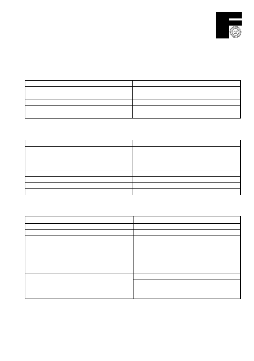
2. Technical data
GAS MAXIMUN OF RANGE MINIMUM OF RANGE
HEAT INPUT 20 KW 68,200 Btu/h 10 kW 34,100 Btu/h
HEAT OUTPUT 16 KW 55,000 Btu/h 7.3 kW 25,000 Btu/h
BURNER PRESSURE 12 mbar 4.7 in wg 2.4 mbar 1.0 in wg
GAS RATE - AFTER 10 MINUTES 1.9 m
GAS CONNECTION SIZE / POSITION 1/2" Bsp / left hand side, rear base
WATER OPEN VENTED SEALED
MAXIMUN HEAD OR PRESSURE 30 m 43.5 psi 3.0 bar 43.5 psi
MINIMUM HEAD OR PRESSURE 0.2 m 8" 0.8 bar 11.6 psi
MAXIMUM FLOW TEMPERATURE 85° C85° C
TEMPERATURE DIFFERENTIAL 11° C
MINIMUM WATER FLOW RATE 0.36 m3/h 12.7 ft3/h
WATER CONTENT 0.5 litres 0.11 gal.
CONNECTIONS 22 mm
3
/h 66 ft3/H 0.95 m3/h 33 ft3/h
if pressurised type
beetween flow and return connections, recommended
compression, right hand side, rear, top
ELECTRICAL
SUPPLY Mains supply 230 V ~ 50 Hz fused 3 Amp.
POWER CONSUMPTION 50 Watt (without pump)
CONNECTIONS MAINS / CONTROL 5 wire electrical lead
Brown - Live Permanent
Blue - Neutral mains supply
Green/Yellow - Earth 230 V ~
Black - Switched Live from external controls
Red - Live to external controls
CONNECTIONS PUMP 3 wire electrical lead
Brown - Live To
Blue - Neutral circulating
Green/Yellow - Earth pump
}
}
5

3. Boiler flow diagram
ROMA 55 FF
6

ROMA 55 FF
4. Key boiler flow diagram
POS. G.C. No. DESCRIPTION Q.ty
3. Flue/air intake (side outlet) 1
16. Complete fan RL 85/0034A1 3025LH 422 1
21a. Main injector N.G. 1.25 9
21b. Main injector L.P.G. 0.72 9
23. Thermocouple 1
24. Complete spark electrode 1
25. Pilot 1
27. Copper heat exchanger 1
43. Air pressure switch 1
44. Combination gas valve V4600C 1193 1
49. Overheat cut/off thermostat 1
50. Central heating limit thermostat 1
58. Combustion chamber pressure test point (+) 1
59. Flue outlet pressure test point (-) 1
63. C.H. boiler thermostat 1
66. Microswitch combination gas valve 1
67. Ignition transformer (CAST) 1
79. Capacitor fan IMF 1
80. Complete P.C.B. VF.1 1
87. Venturi flue testpoint 1
103. Relay 1
104. Fuse 2A 1
105. Complete burner set 1
106. Gascock 1
107. Flue/air intake flange rear outlet 1
108. Combustion chamber outlet cover 1
109. Combustion chamber insulation, back and sides 1
110. Eco split wire 1
111. Combustion chamber front panel 1
112. Pilot injector N.G. 0.27 1
112b. Pilot injector L.P.G. 0.22 1
133. Pump overrun thermostat 1
7
5. Installation data
MAX. 150 mm.
*h/3 min/mm
INDIRECT
CYLINDER.
ROMA 55 FF
INDYRECT
CYLINDER
*h/3 min/mm
HEATING
SYSTEM
ROMA
* h = maximum head developed by pump.
5.1 Water System
General
1. The ROMA 55 FF will supply central heating and, via an indirect cylinder, stored hot water.
2. All water systems must be in accordance with the Bye-Laws of the Local Water Undertaking.
3. Only fully pumped systems can be used.
4. Two pipe heating systems are recommended.
5. Systems can be either of the open (vented) or sealed type.
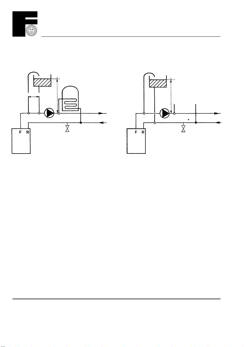
5.2 Open (Vented) System
1. Further guidance: BS 5449, BS 6798 and British Gas Publications.
2. Two typical systems are shown above. Note that close coupled or combined feed and vents are permitted.
3. Cold Feed: Minimum 15 mm copper but minimum 22 mm if combined with open vent.
4. Open Vend: Minimum 22 mm copper.
5. No valves between the boiler and the open vent.
6. A Bypass must be fitted which allows a minimum flow of 6 litres/min. (1.3 gal/min.)
OPEN VENTED
CLOSE COUPLED
FEED AND VENT.
ROMA
OPEN VENTED
FEED ON RETURN
HEATING
SYSTEM.
8
ROMA 55 FF
ROMA
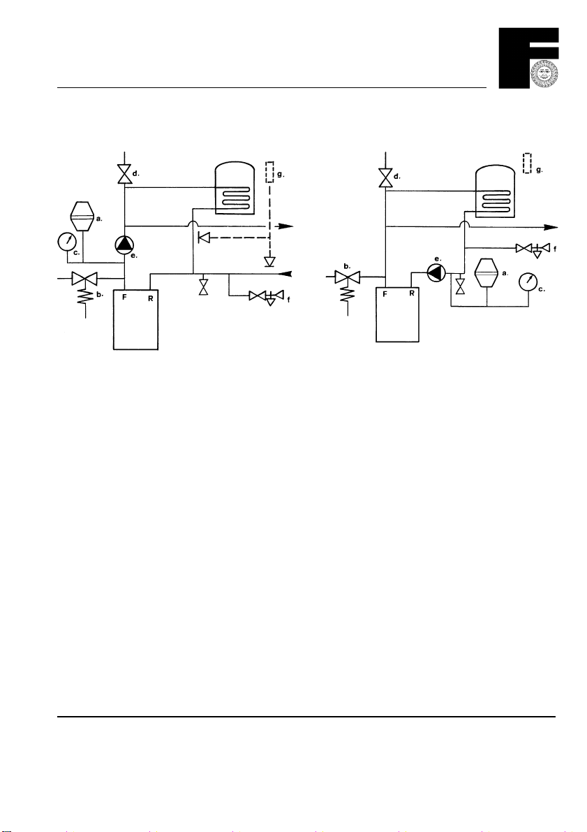
5.3 Sealed System
1. Further guidance: BS 5449, BS 6798, BS 7074 Part 1, British Gas Publications.
2. Two typical sealed systems are shown, above.
3. COMPONENTS:
a) EXPANDION VESSEL.
To BS 4814. Sized according to BS 5449 and/or BS 7074 Part 1. Positioned on the inlet to the pump.
b) SAFETY VALVE.
Always on the flow and next to the boiler. Non adjustable and set to 3 bar. Routed direct to drain in an area not
susceptable to freezing, nor where it is hazardous. Do not reduce pipe size from that on the valve.
c) PRESSURE GAUGE (May incorporate a temperature gauge).
Must have a fill pressure indicator, and be readily visible to the User. Range 0 to 4 bar.
d) AIR VENT. Highest point of the system.
e) PUMP. Suitable for the system. See 5.4.
f) FILLING POINT.
Shall be at low level, in accordance with local Water Authority requirement, and generally have a stop valve to BS 1010,
as well as a double check valve. Filling can be achieved either by means of a temporary hose or via a cistern used for
no other purpose, with a minimum static head of 300 mm to the highest point of system.
g) SYSTEM MAKE UP.
Can be achieved either automatically - from an independent cistern used for no other purpose, or from a manually filled
top up bottle through a double check valve, OR manually, by a temporary hose connection.
IMPORTANT
Any method of filling and of make up MUST comply with Regulations of the Local Water Authority.
SEALED SYSTEM
PUMP ON THE FLOW
ROMA
SEALED SYSTEM
PUMP ON THE FLOW
9
ROMA 55 FF
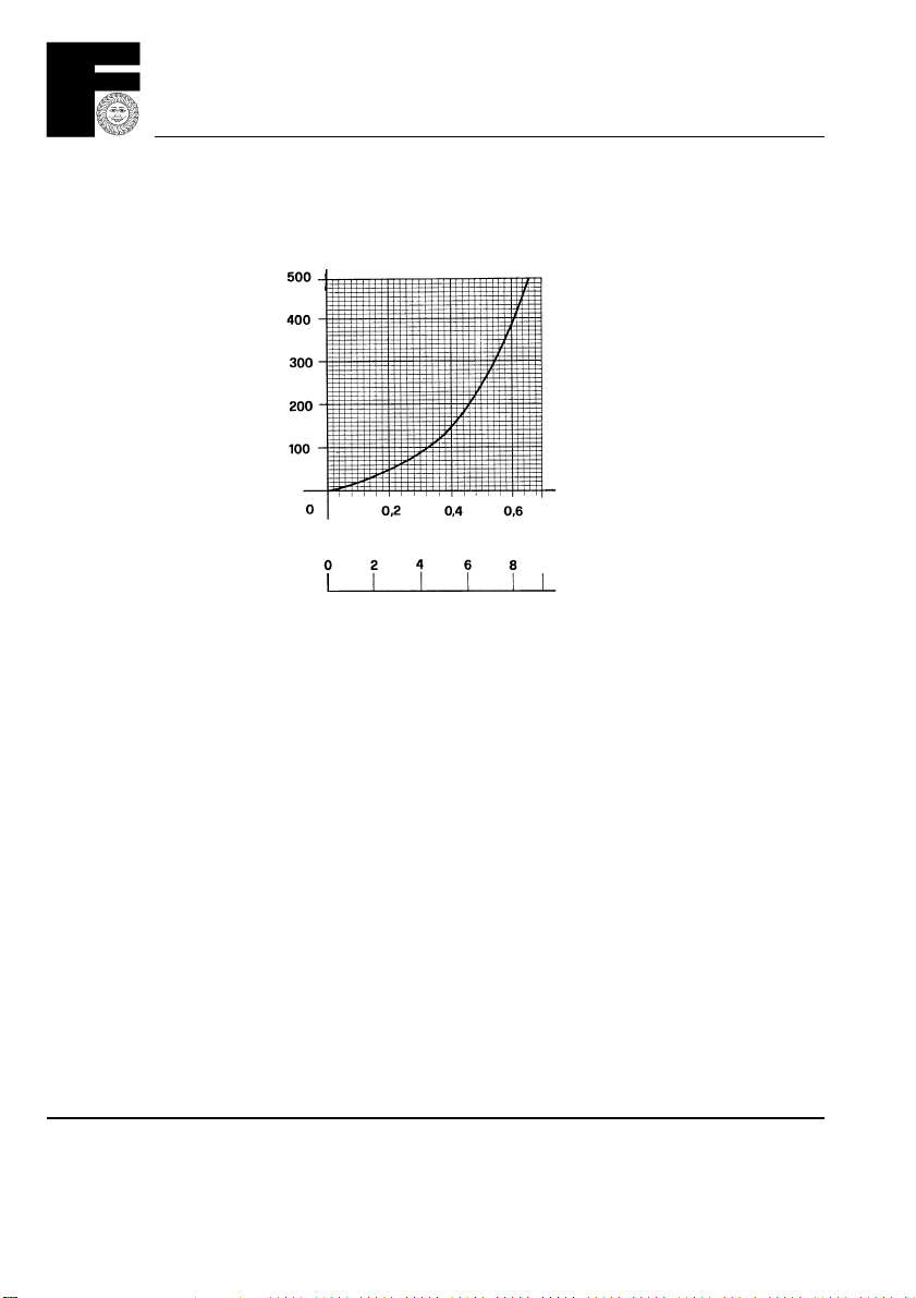
Boiler pressure loss
mbar
litres/sec
gal/min
5.4 Pump selection
Suitable pump should be fitted taking due account of the pressure loss across the boiler.
Pump to comply with BS 1394. A minimum flow rate of 6 litres/min (1.3 gal/min) is required.
5.5 Drain points
Must be provided to enable the system to be drained - taps to BS 2879.
5.6 Hot water storage cylinder
Must be either of the indirect coil type or a direct cylinder suitably adapted by fitment of an immersion calorifier. Direct
cylinders must not be used.
5.7 Quality of components
All components, fittings, and joint must be suitable for temperatures up to 110°C and, for sealed systems, pressures
up to 3 bar.
5.8 Flushing
Any system, new or old, must be flushed in accordance with the Commissioning Instructions. It is essential that as much
residual sludge and debris be removed as is possible.
10

ROMA 55 FF
5.9 Flue system
1. Further guidance: BS 5440 Part 1.
2. Flue types: Fanned. Balanced, and hence appliance is room sealed.
3. Termination: Outside. Horizontal. Vertical.
4. Direction: From boiler, to rear, either side and vertical (side & vertical required optional flue turret).
5. Maximum length: Two separate flue kits are available.
KIT Part No. MAXIMUM LENGHT mm
Rear - Inner to outer wallface Side - Boiler side to outer wallface
A (1 m) 3980221 820 808
B (2m) 3980222 Not Permitted 1808
Vertical & Side flue turret part No. 3980220
Vertical terminal part No. 39800570
Order one kit only - joining of flue kits is not permitted.
With vertical termination maximum flue length is 2 metres.
5.10 Se duct termination
Termination in the Se Duct is exactly as termination on an outside wall. No adaptation of the flue system is required.
Simply ensure that the plastic air duct is flush the inside face of the Se Duct.
Do not remove the terminal.
Don't foget that on Se Duct you will need an adequate width inside to push the flue system through any obstructions
before entering the Se Duct. See section 7 (page 13).
5.11 Ventilation
1. Further guidance: BS 5440, Part 2.
2. Ventilation for a room or space: None Required - This is a room sealed appliance.
3. Ventilation for a compartment: Cooling air is required:
MINIMUM AIR VENT FREE AREA. COMPARTMENTS
VENT Compartment ventilated to:
POSITION Room or space Direct to outside
HIGH LEVEL 180 cm
LOW LEVEL 180 cm
2
2
90 cm
90 cm
2
2
11

ROMA 55 FF
6. Terminal position (outside)
A Quinnell Barratt and Quinnell guard (part. no. C2) should be screwed to the wall centrally over the terminal, when the
distance is less than 2 m above a balcony, above ground or above a flat roof to which people have access.
6.01 Terminal position
Minimum Clearances (mm)
POS. mm TERMINAL POSITION
A 300 Directly below an opening
B 75 Below gutters, soil and drain pipes
C 200 Below eaves
D 200 Below balconies, car port roof
E 75 From vertical drain or soil pipe
F 300 From internal or external corner
G 300 Above ground, roof, or balcony
H 600 From surface facing the terminal
I 1200 From terminal facing the terminal
J 1200 From opening in car port, to dwelling
K 1500 Vertically from a terminal on same wall
L 300 Horizontally from a terminal on same wall
1000 • Below plastic gutter
500 • Below painted eaves etc.
Otherwise protect with suitable shield at least 1 m long
}
12
ROMA 55 FF
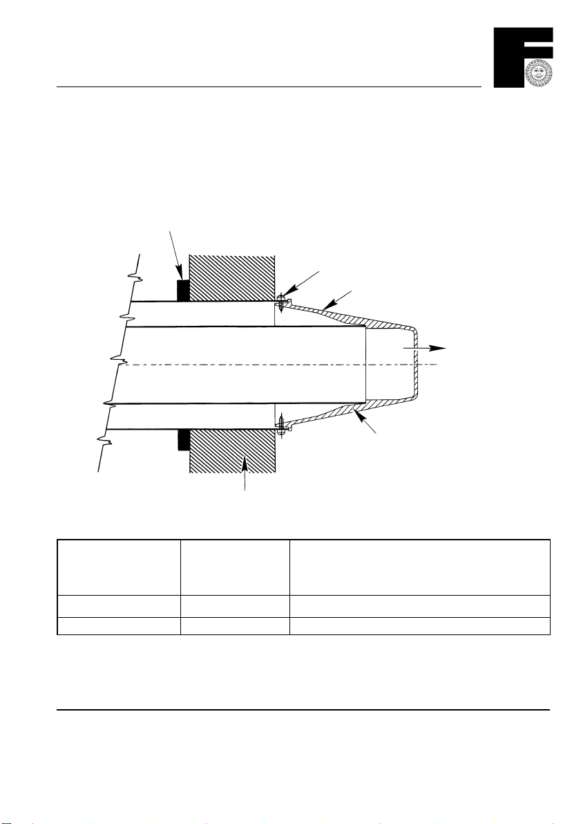
7. Terminal position horizontal, seduct, u duct
Standard se duct or u duct
Terminal position - The terminal must be situated relative to the Seduct or U Duct as shown.
Horizontal Only.
Flue lengths - Two lengths are available.
MAKE GOOD AND SEAL
FIXING SCREW
AIR INTAKE
TERMINAL
FLUE OUTLET
WALL
Part No. / Item Rear Flues Side Flues
Wall Thickness Wall Thickness + Distance from side wall
(Max) (Max)
3980221 820 mm 808 mm
3980222 not permited 1808 mm
Installation - The exposed wall face MUST be made good and SEALED.
Note that the air duct MUST be retained by screws at the appliance. Further guidance BS 5440: Part 1.
13

ROMA 55 FF
8. Location
1. Further guidance: BS 6798.
2. Not suitable for external installation.
3. Must be mounted on a suitable load bearing flat wall.
4. Combustable walls are not suitable.
5. Dimensions of the boiler.
WEIGHT EMPTY 30 kg 66 lb
WEIGHT FULL 30.5 kg 67 lb
HEIGHT 655 mm 26.8 in
WIDTH 370 mm 14.6 in
DEPTH 300 mm 11.7 in
CLEARANCES
IN FRONT 600 mm 24.0 in
TO SIDES 5 mm 0.2 in
ABOVE 100 mm 4.0 in
BELOW 150 mm 6.0 in
6. The space for installation will need to take into account minimum clearences required for safe operation and
subsequent Servicing. Note that the minimum clearance at the front can be via an openable door.
* A top clearance of at least 150 mm (6 in) is desiderable at installation.
7. The boiler may be installed in any room or internal space, although particular attention is drawn to the requirements
of the current. I.E.E. Wiring Regulations, and, in Scotland, the electrical provisions of the Building Regulation applicable
in Scotland, with respect to the installation of the boiler in a room or internal space containing a bath or shower. When
this boiler is installed in a room containing a bath or shower, any electrical switch or appliance control, utilising mains
electricity should be so situated that it cannot be touched by a person using the bath or shower.
14
 Loading...