

Page 1

cod. -- — 11/2010 (Rev. 00)
ECONCEPT SOLAR ST
INSTRUCTIONS FOR USE, INSTALLATION AND MAINTENANCE
Page 2

ECONCEPT SOLAR ST
2 EN
B
Declaration of conformity
Manufacturer: FERROLI S.p.A.
Address: Via Ritonda 78/a 37047 San Bonifacio VR Italy
declares that this unit complies with the following EU directives:
• Gas Appliance Directive 2009/142
• Efficiency Directive 92/42
• Low Voltage Directive 73/23 (amended by 93/68)
• Electromagnetic Compatibility Directive 89/336 (amended by 93/68)
President and Legal Representative
Cav. del Lavoro
Dante Ferroli
B
This symbol indicates "Caution" and is placed next to all safety warnings. Strictly follow
these instructions in order to avoid danger and damage to persons, animals and things.
A
This symbols calls attention to a note or important notice.
cod. -- - 11/2010 (Rev. 00)
• Carefully read the warnings in this instruction booklet since they provide important information on safe
installation, use and maintenance.
• This instruction booklet is an integral part of the
product and must be carefully kept by the user for future reference.
• If the unit is sold or transferred to another owner or if
it is to be moved, always make sure that the booklet
accompanies the boiler so that it can be consulted
by the new owner and/or installer.
• Installation and maintenance must be carried out by
professionally qualified personnel, according to current regulations and the manufacturer's instructions.
• Incorrect installation or poor maintenance can cause
damage or physical injury. The manufacturer declines any responsibility for damage caused by errors in installation and use or by failure to follow the
manufacturer's instructions.
• Before carrying out any cleaning or maintenance operation, disconnect the unit from the electrical power supply using the switch and/or the special cut-off devices.
• In case the unit breaks down and/or functions poorly,
deactivate it, do not make any attempt to repair it or
directly intervene. Contact professionally qualified
personnel. Any repair/replacement of products must
only be carried out by qualified professional personnel using exclusively genuine parts. Failure to comply with the above could affect the safety of the unit.
• Periodical maintenance carried out by qualified personnel
is essential for guaranteeing good operation of the unit.
• This unit must only be used for the purpose for which
it was designed. Any other use is considered improper and therefore hazardous.
• After removing the packing, check the integrity of the
contents. Packing materials must not be left within the
reach of children as they are potentially hazardous.
• In case of doubt do not use the unit, and contact the
supplier.
• The images shown in this manual are a simplified
representation of the product. In this representation
there may be slight, unimportant differences with the
supplied product.
Page 3

ECONCEPT SOLAR ST
3
cod. -- - 11/2010 (Rev. 00)
1 Operating instructions ............................................................................................................ 4
1.1 Introduction............................................................................................................................................. 4
1.2 Control panel ..........................................................................................................................................5
1.3 Lighting and turning off........................................................................................................................... 7
1.4 Adjustments............................................................................................................................................ 8
2 Installation .............................................................................................................................. 13
2.1 General Instructions .............................................................................................................................13
2.2 Place of installation ............................................................................................................................. 13
2.3 Plumbing connections ..........................................................................................................................13
2.4 Gas connection .................................................................................................................................... 14
2.5 Electrical connections........................................................................................................................... 15
2.6 Fume ducts........................................................................................................................................... 16
2.7 Condensate drain connection...............................................................................................................20
3 Service and maintenance......................................................................................................21
3.1 Adjustments.......................................................................................................................................... 21
3.2 Starting ................................................................................................................................................. 22
3.3 Maintenance......................................................................................................................................... 26
3.4 Trouble shooting................................................................................................................................... 27
4 Technical data and characteristics ...................................................................................... 29
4.1 Dimensions and connections ...............................................................................................................29
4.2 General view and main components ....................................................................................................30
4.3 Water circuit .........................................................................................................................................31
4.4 Technical data table .............................................................................................................................33
4.5 Diagrams ..............................................................................................................................................34
4.6 Wiring diagram .....................................................................................................................................36
4.7 DBM29 (ECOTRONIC tech) - Solar Controller ....................................................................................38
4.8 FZ4B low temperature zone card .........................................................................................................47
Page 4

ECONCEPT SOLAR ST
4 EN
cod. -- - 11/2010 (Rev. 00)
1. Operating instructions
1.1 Introduction
Thank you for choosing ECONCEPT SOLAR ST, a floor-standing boiler with incorporated solar hot water tankFERROLI featuring advanced design, cutting-edge technology, high reliability and quality construction . Please read this
manual carefully since it provides important information on safe installation, use and maintenance
ECONCEPT SOLAR ST is a high-efficiency, low emissions, sealed chamber premix condensing heat generator for
heating and hot water production, running on natural gas or LPG and equipped with a microprocessor control system.
The boiler shell consists of an aluminium lamellar exchanger and a ceramic premix burner equipped with electronic
ignition and ionisation flame control, modulating speed fan and modulating gas valve.
The boiler is arranged for connection to one or more solar collectors, which are used for domestic hot water production
. In fact, the unit has a special, incorporated stratified solar hot water tank and an advanced circuit with variable-speed
solar pump , for maximising the saving obtainable from a solar panel system.
Regarding the production of hot water for heating, ECONCEPT SOLAR ST it is fitted standard with a double internal
circulation, enabling the simultaneous and independent management of two heating zones: a low temperature zone
(floor system) and a high temperature zone (radiators, towel warmers, etc.).
Page 5
ECONCEPT SOLAR ST
5EN
cod. -- - 11/2010 (Rev. 00)
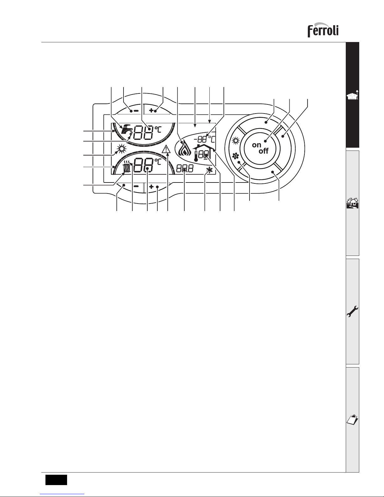
1.2 Control panel
fig. 1 - Control panel
Key
1 = DHW temperature setting decrease button
2 = DHW temperature setting increase button
3 = Heating system temperature setting decrease
button (high temperature zone)
4 = Heating system temperature setting increase
button (high temperature zone)
5 = Display
6 = Summer / Winter mode selection button
7 = Economy / Comfort mode selection button
8 = Reset button
9 = Unit On / Off button
10 = "Sliding Temperature" menu button (high tem-
perature zone)
11 = Set DHW temperature reached
12 = DHW symbol
13 = DHW mode
14 = DHW outlet temperature / setting (flashing dur-
ing "Exchanger protection" function)
15 = Eco (Economy) or Comfort mode
16 = External sensor temperature (with optional ex-
ternal probe)
17 = Appears on connecting the external Probe or the
Remote Timer Control (optionals)
18 = Room temperature (with optional Remote Timer
Control - low temperature zone)
19 = Burner lit and actual power (flashing during
"Flame protection" function)
20 = Antifreeze operation
21 = Heating system pressure
22 = Fault
23 = Heating delivery temperature / setting - high
temperature zone (flashing during “Exchanger
protection” function )
24 = Heating symbol
25 = Heating mode
26 = Set heating delivery temperature reached
27 = Summer mode
e
c
o
c
o
m
f
o
r
t
m
o
d
e
r
e
s
e
t
ecomfort
bar
5
7910
21
86
43
12 14
11
13
15 16
17182021222325
24
26
27
19
Page 6

ECONCEPT SOLAR ST
6 EN
cod. -- - 11/2010 (Rev. 00)
Indication during operation
Heating
A heating demand (generated by the Room Thermostat or Remote Timer Control) is indicated by flashing of the hot air
above the radiator (details 24 and 25 - fig. 1).
The display (detail 23 - fig. 1) shows the actual heating delivery temperature and, during heating standby time, the message "d2".
The heating graduation marks (detail 26 - fig. 1) light up as the heating sensor temperature reaches the set value.
fig. 2
Domestic hot water (DHW)
A hot water tank heating demand is indicated by flashing of the hot water under the tap (details 12 and 13 - fig. 1).
The display (detail 14 - fig. 1) shows the actual hot water outlet temperature and, during DHW standby time, the message "d1".
The DHW graduation marks (detail 11 - fig. 1) light up as the hot water tank sensor temperature reaches the set value.
fig. 3
Exclude hot water tank (economy)
Hot water tank temperature maintaining/heating can be excluded by the user. If excluded, domestic hot water will only
be delivered by the solar circuit; the latter is managed by the controller DBM29 whose specifications are given in
cap. 4.7 "DBM29 (ECOTRONIC tech) - Solar Controller".
When hot water tank heating is activated (default setting), the COMFORT symbol (detail 15 - fig. 1) is activated on the
display, and when off, the ECO symbol (detail 15 - fig. 1) is activated on the display.
The hot water tank can be deactivated by the user (ECO mode ) by pressing the economy/comfort button (detail 7 fig. 1). To activate the COMFORT mode, press theeconomy/comfort button (detail 7 - fig. 1) again.
e
c
o
c
o
m
f
o
r
t
m
o
d
e
r
e
s
e
t
eco
bar
e
c
o
c
o
m
f
o
r
t
m
o
d
e
r
e
s
e
t
eco
bar
e
c
o
c
o
m
f
o
r
t
m
o
d
e
r
e
s
e
t
bar
e
c
o
c
o
m
f
o
r
t
m
o
d
e
r
e
s
e
t
comfort
bar
comfort
Page 7

ECONCEPT SOLAR ST
7EN
cod. -- - 11/2010 (Rev. 00)
1.3 Lighting and turning off
Boiler not electrically powered
fig. 4 - Boiler not powered
B
The antifreeze system does not work when the power and/or gas to the unit are turned off. To avoid damage
caused by freezing during long idle periods in winter, it is advisable to drain all the water from the boiler, DHW
circuit and system; or drain just the DHW circuit and add a suitable antifreeze to the heating system, complying
with that prescribed in sec. 2.3.
Boiler lighting
Switch on the power to the unit.
fig. 5 - Boiler ignition
• For the following 180 seconds the display will show FH which identifies the heating system air venting cycle.
• During the first 5 seconds the display will also show the card software version.
• Open the gas cock ahead of the boiler.
• When the message FH disappears, the boiler is ready to operate automatically whenever domestic hot water is
drawn or in case of a room thermostat demand.
Turning the boiler off
Press the button (detail 9 - fig. 1) for 1 second.
fig. 6 - Turning the boiler off
e
c
o
c
o
m
f
o
r
t
m
o
d
e
r
e
s
e
t
e
c
o
c
o
m
f
o
r
t
m
o
d
e
r
e
s
e
t
e
c
o
c
o
m
f
o
r
t
m
o
d
e
r
e
s
e
t
Page 8

ECONCEPT SOLAR ST
8 EN
cod. -- - 11/2010 (Rev. 00)
When the boiler is turned off, the electronic board is still powered.
Domestic hot water and heating operation are disabled. The antifreeze system remains activated.
To re-light the boiler, press the button (detail 9 fig. 1) again for 1 second.
fig. 7
The boiler will be immediately ready to operate whenever domestic hot water is drawn or in case of a room thermostat demand.
1.4 Adjustments
Summer/Winter Switchover
Press the button (part 6 - fig. 1) for 1 second.
fig. 8
The display will activate the Summer symbol (part 27 - fig. 1): the boiler will deliver tap water only. The antifreeze system
stays on.
To turn off Summer mode, press button (part 6 - fig. 1) again for 1 second.
Heating temperature adjustment (high temperature zone)
Use the heating buttons (details 3 and 4 -
fig. 1
) to adjust the temperature from a min. of 20°C to a max. of 90°C.
fig. 9
This temperature becomes the maximum system delivery temperature also for the low temperature zone. Do not set a
lower value than that of “Heating temperature adjustment (low temperature zone)”:
e
c
o
c
o
m
f
o
r
t
m
o
d
e
r
e
s
e
t
eco
bar
e
c
o
c
o
m
f
o
r
t
m
o
d
e
r
e
s
e
t
eco
bar
e
c
o
c
o
m
f
o
r
t
m
o
d
e
r
e
s
e
t
eco
bar
Page 9

ECONCEPT SOLAR ST
9EN
cod. -- - 11/2010 (Rev. 00)
Heating temperature adjustment (low temperature zone)
With optional remote timer control installed
Use the "Heating temperature adjustment" button (see relevant manual) to adjust the temperature from a min. of 10°C
to a max. of 40°C.
Without optional remote timer control installed
The heating temperature adjustment for the low temperature zone is fixed at 40°C.
This setting must only be modified by qualified Personnel.
Room temperature adjustment
Room temperature adjustment of the high temperature zone can only be managed by a room thermostat; whereas room
temperature adjustment of the low temperature can be managed by a room thermostat or a remote timer control.
Room temperature adjustment (with optional room thermostat)
Using the room thermostat, set the temperature required in the rooms. If the room thermostat is not present, the boiler
will keep the system at the set system delivery set point temperature.
Room temperature adjustment (with optional remote timer control)
Using the remote timer control, set the required temperature in the rooms. The boiler will adjust the system water according
to the required room temperature. For operation with remote timer control, refer to the relevant instruction manual.
Domestic hot water (DHW) temperature adjustment
Use the DHW buttons (details 1 and 2 - fig. 1) to adjust the temperature from a min. of 10°C to a max. of 65°C.
fig. 10
Sliding temperature
When the optional external probe is installed, the control panel display (detail 5 - fig. 1) shows the actual outside temperature read by the probe. The boiler control system works with "Sliding Temperature". In this mode, the heating system temperature is controlled according to the outside weather conditions in order to ensure high comfort and energy
saving throughout the year. In particular, as the outside temperature increases, the system delivery temperature is decreased according to a specific "compensation curve".
With the Sliding Temperature adjustment, the temperature set with the heating buttons (details 3 and 4 - fig. 1) becomes
the maximum system delivery temperature (high and low temperature zone). It is advisable to set a maximum value to
allow system adjustment throughout its useful operating range.
The boiler must be adjusted at the time of installation by qualified personnel. Adjustments can in any case be made by
the user to improve comfort .
e
c
o
c
o
m
f
o
r
t
m
o
d
e
r
e
s
e
t
eco
bar
Page 10

ECONCEPT SOLAR ST
10 EN
cod. -- - 11/2010 (Rev. 00)
Compensation curve and curve offset - High Temperature Zone
Press the button (detail 10 - fig. 1) once to display the actual compensation curve (fig. 11), which can be modified
with the DHW buttons (details 1 and 2 - fig. 1).
Adjust the required curve from 1 to 10 according to the characteristic (fig. 13).
By setting the curve to 0, sliding temperature adjustment is disabled.
fig. 11 - Compensation curve
Press the heating buttons (details 3 and 4 - fig. 1) to access parallel curve offset (fig. 14), modifiable with the
DHW buttons (details 1 and 2 - fig. 1).
fig. 12 - Parallel curve shift
Press the button (detail 10 - fig. 1) again to exit parallel curve adjustment mode.
Compensation curve and curve offset - Low Temperature Zone with optional Remote Timer Control
connected
Refer to the relevant instruction manual.
Compensation curve and curve offset - Low Temperature Zone without optional Remote Timer Control connected
Press the ECONOMY/COMFORT button (detail 7 - fig. 1) for 10 seconds; parameter o01 or the actual compensation
curve is displayed, which can be modified with the DHW buttons (details 1 and 2 - fig. 1).
Adjust the required curve from 1 to 10 according to the characteristic (fig. 13). By setting the curve to 0, sliding temperature adjustment is disabled.
Press the heating button (detail 4 - fig. 1) to access parameter o02 or parallel curve offset (fig. 14), modifiable with the
DHW buttons (details 1 and 2 - fig. 1).
Press the ECONOMY/COMFORT button (detail 7 - fig. 1) again for 10 seconds to exit parallel curve adjustment mode .
Page 11

ECONCEPT SOLAR ST
11EN
cod. -- - 11/2010 (Rev. 00)
References for Compensation curve and curve offset
If the room temperature is lower than the required value, it is advisable to set a higher order curve and vice versa. Proceed by increasing or decreasing in steps of one and check the result in the room.
fig. 13 - Compensation curves
fig. 14 - Example of parallel compensation curve shift
Adjustments from remote timer control (for Low Temperature Zone only)
A
If the Remote Timer Control (optional) is connected to the boiler, the above adjustments are managed according to that given in table 1. Also, the control panel display (detail 5 - fig. 1) shows the actual room temperature
read by the Remote Timer Control.
Table. 1
DHW temperature adjustment Adjustment can be made from the Remote Timer Control menu and the boiler
control panel.
Eco/Comfort selection On disabling DHW from the Remote Timer Control menu, the boiler selects
the Economy mode. In this condition, the ECONOMY/COMFORT button
(detail 7 - fig. 1) on the boiler panel is disabled .
On enabling DHW from the Remote Timer Control menu, the boiler selects
the Comfort mode. In this condition , one of the two modes can be selected
with the ECONOMY/COMFORT button (detail 7 - fig. 1) on the boiler panel .
20
30
40
50
60
70
80
90
85
20 10 0 -10 -20
1
2
3
4
5
68910 7
20
30
40
50
60
70
80
90
85
20 10 0 -10 -20
1
2
3
4
5
6
8910
7
20 10 0 -10 -20
20
30
40
50
60
70
80
90
85
1
2
3
4
568910 7
OFFSET = 20 OFFSET = 40
Page 12

ECONCEPT SOLAR ST
12 EN
cod. -- - 11/2010 (Rev. 00)
System water pressure adjustment
The filling pressure with system cold, read on the boiler water gauge, must be approx. 1.0 bar. If the system pressure
falls to values below minimum, the boiler card will activate fault F37 (fig. 15).
fig. 15 - Low system pressure fault
Operate the filling cock (detail 1 - fig. 16) and bring the system pressure to a value above 1.0 bar.
At the bottom of the boiler there is a pressure gauge (detail 2 - fig. 16) to show the pressure even when there is no power
supply.
fig. 16 - Filling cock
A
Once the system pressure is restored, the boiler will activate the 180-second air venting cycle indicated on the
display by FH.
At the end of the operation always close the filling cock (detail 1 - fig. 16)
e
c
o
c
o
m
f
o
r
t
m
o
d
e
r
e
s
e
t
Page 13

ECONCEPT SOLAR ST
13EN
cod. -- - 11/2010 (Rev. 00)
2. Installation
2.1 General Instructions
BOILER INSTALLATION MUST ONLY BE PERFORMED BY QUALIFIED PERSONNEL, IN ACCORDANCE WITH ALL THE
INSTRUCTIONS GIVEN IN THIS TECHNICAL MANUAL, THE PROVISIONS OF CURRENT LAW, THE PRESCRIPTIONS
OF NATIONAL STANDARDS AND LOCAL REGULATIONS AND THE RULES OF PROPER WORKMANSHIP
2.2 Place of installation
The combustion circuit is sealed with respect to the place of installation, therefore the unit can be installed in any room.
However, the place of installation must be sufficiently ventilated to prevent the creation of dangerous conditions in case
of even small gas leaks. This safety standard is required by EEC Directive no. 90/396 for all gas units, including those
with sealed chamber.
Therefore the place of installation must be free of dust, flammable materials or objects, or corrosive gases. The room
must be dry and not subject to freezing.
A
If the unit is enclosed in a cabinet or mounted alongside, a space must be provided for removing the casing
and for normal maintenance operations
2.3 Plumbing connections
Important
The heating capacity of the unit must be previously established by calculating the building's heat requirement according
to the current regulations. The system must be provided with all the components for correct and regular operation. It is
advisable to install shutoff valves between the boiler and heating system allowing the boiler to be isolated from the system if necessary.
B
The safety valve outlet must be connected to a funnel or collection pipe to prevent water spurting onto the floor
in case of overpressure in the heating circuit. Otherwise, if the discharge valve cuts in and floods the room,
the boiler manufacturer cannot be held liable.
Do not use the water system pipes to earth electrical appliances.
Before installation, carefully wash all the pipes of the system to remove any residuals or impurities that could affect proper operation of the unit.
B
Also, a filter must be installed on the system return piping to prevent impurities or sludge from the system clogging and damaging the heat generators.
The filter must be installed when replacing generators in existing systems. The manufacturer declines any liability for damage caused to the generator by failure to install or inadequate installation of this filter.
Carry out the relevant connections according to the diagram in sec. 4.1and the symbols given on the unit.
The unit has an internal double circulation, which enables the management of two heating zones: a low temperature
zone (floor system) and a high temperature zone (radiators, towel warmers,etc.).
Solar system
The unit has a specific internal circuit for connection to one or more external solar collectors. The internal circuit of
ECONCEPT SOLAR ST comprises: stratified solar hot water tank with solar coil, flow limiter, filling unit, solar safety
valve, variable-speed pump and solar expansion tank. Make the corresponding connections , respecting the instructions
given below.
• It is best to use steel or copper pipes in the solar circuit. Given the high temperatures the heat transfer fluid can
reach, the use of plastic pipes , e.g. in PE or similar materials, is not allowed. Deformation or breakage of the pipes
can cause a general system failure !
• The widths of the pipes must be correctly sized . In particular, too large a size slows the system speed and reduces
its efficiency . To minimise pressure loss in the solar circuit, the speed of flow in the copper pipe must not exceed
1.5 m/s. For ideal transmission of heat, for the collectors a nominal flow of 40 l/h for every m2 of gross collector area
is necessary .
• All the components of the system must be sized in order to ensure an even volumetric flow rate with the required
nominal flow rate .
• The pipes outside the boiler must be provided with adequate thermal protection to prevent excessive heat loss. In
particular, in case if pipes laid outdoors, use insulation resistant to atmospheric agents , UV rays and bird damage.
Page 14

ECONCEPT SOLAR ST
14 EN
cod. -- - 11/2010 (Rev. 00)
• The solar circuit must be perfectly tight. Check all the joins between pipes and correct execution of any welds. Use
pressure fittings only of the thermal resistance guaranteed by their manufacturer is equal to 200ºC.
• The presence of air in the solar circuit considerably affects its efficiency . It is necessary to install venting devices in
the highest points of the solar circuit (e.g. at the tops of the columns) and make sure the system is completely vented
after commissioning and after every maintenance operation . The delivery and return pipes must be installed with
adequate slopes towards the vents, avoiding the creation of air pockets. Automatic or manual devices (recommended) can be used as venting devices. The venting devices must be resistant to temperatures up to 150°C. If the system is not working and the automatic venting devices are not blocked, steam can come out . Therefore the automatic
venting devices must be blocked while the system is working.
• The solar circuit must be filled with suitable heat transfer fluid, specific for solar systems. Recommended products:
"FERSOL LT" or "FERSOL ULTRA LT" which provide adequate antifreeze protection for temperatures to -12°C and
-25°C respectively. In general, choose the type of fluid according to the outside temperature in relation to the heating
system in the place of installation . Add approx. 7°C to this temperature (e.g. -5°C) as a safety factor : therefore in
the above example, the antifreeze protection of "FERSOL LT" fluid will suffice. FERSOL premixed solar fluid contains non-toxic propylene glycols and corrosion inhibitors thermostable to 300°C (peak temperature limit condition
reachable for very short periods).
• For solar system filling and venting operations, refer to sec. 3.2. For periodical fluid and maintenance checking operations, refer tosec. 3.3.
System water charcteristics
In the presence of water harder than 25° Fr (1°F = 10ppm CaCO3), the use of suitably treated water is advisable in order
to avoid possible scaling in the boiler. The treatment must not in any case reduce the hardness to values below 15°F
(Decree 236/88 for uses of water intended for human consumption). Water treatment is indispensable in the case of
very large systems or with frequent replenishing of water in the system. If partial or total emptying of the system becomes necessary in these cases, it is advisable to refill it with treated water.
Antifreeze system, antifreeze fluids, additives and inhibitors
The boiler is equipped with an antifreeze system that turns on the boiler in heating mode when the system delivery water
temperature falls under 6°C. The device will not come on if the electricity and/or gas supply to the unit are cut off. If it
becomes necessary, it is permissible to use antifreeze fluid, additives and inhibitors only if the manufacturer of these
fluids or additives guarantees they are suitable for this use and cause no damage to the heat exchanger or other components and/or materials of the boiler unit and system. It is prohibited to use generic antifreeze fluid, additives or inhibitors that are not expressly suited for use in heating systems and compatible with the materials of the boiler unit and
system.
2.4 Gas connection
B
Before making the connection, ensure that the unit is arranged for operation with the type of fuel available and
carefully clean all the pipes of the gas system to remove any residues that could affect good functioning of the
boiler.
The gas must be connected to the relative connector (see fig. 33) in conformity with current standards, with rigid metal
pipes or with continuous flexible s/steel wall tubing, placing a gas cock between the system and the boiler. Make sure
that all the gas connections are tight. The capacity of the gas meter must be sufficient for the simultaneous use of all
equipment connected to it. The diameter of the gas pipe leaving the boiler does not determine the diameter of the pipe
between the unit and the meter; it must be chosen according to its length and loss of head, in conformity with current
standards.
B
Do not use the gas pipes to earth electrical appliances.
Page 15

ECONCEPT SOLAR ST
15EN
cod. -- - 11/2010 (Rev. 00)
2.5 Electrical connections
Connection to the electrical grid
B
The unit's electrical safety is only guaranteed when correctly connected to an efficient earthing system executed according to current safety standards. Have the efficiency and suitability of the earthing system checked
by professionally qualified personnel. The manufacturer is not responsible for any damage caused by failure
to earth the system. Also make sure that the electrical system is adequate for the maximum power absorbed
by the unit, as specified on the boiler dataplate.
The boiler is prewired and provided with a Y-cable and plug for connection to the electricity line. The connections to the
grid must be made with a permanent connection and equipped with a bipolar switch whose contacts have a minimum
opening of at least 3 mm, interposing fuses of max. 3A between the boiler and the line. It is important to respect the
polarities (LINE: brown wire / NEUTRAL: blue wire / EARTH: yellow-green wire) in making connections to the electrical
line. During installation or when changing the power cable, the earth wire must be left 2 cm longer than the others.
B
The user must never change the unit's power cable. If the cable gets damaged, switch off the unit and have it
changed solely by professionally qualified personnel. If changing the electric power cable, use solely “HAR
H05 VV-F” 3x0.75 mm2 cable with a maximum outside diameter of 8 mm.
Solar collector temperature probe
The unit is provided with a temperature probe for positioning on the circuit at the outlet of the last collector .The probe
must be connected to the controller after carrying out the solar circuit filling operations described in sec. 2.3. The controller is located on the left side on the back of the electrical box. The probe must be connected to terminals 5 and 6,
removing the resistances (to be kept for future use).
Room thermostat (optional)
B
CAUTION: The room thermostat must have clean contacts. CONNECTING 230 V. TO THE TERMINALS OF
THE ROOM THERMOSTAT WILL IRREPARABLY DAMAGE THE ELECTRONIC CARD.
When connecting a remote timer control or a timer switch, do not take the power supply for these devices from
their cut-out contacts. Their power supply must be taken with a direct connection from the mains or with batteries, depending on the kind of device.
External probe (optional)
Connect the probe to its respective terminals. The maximum permissible length for the boiler - external probe connection electrical cable is 50 m. A normal 2-wire cable can be used. The external probe should preferably be installed on
the North, North-West wall or that facing the largest area of living room. The probe must never be exposed to the early
morning sun or, insofar as possible, direct sunlight; protect it if necessary. In any case, the probe must not be installed
near windows, doors, ventilation openings, flues or heat sources that could affect the reading.
fig. 17 - External probe positioning not recommended
Page 16

ECONCEPT SOLAR ST
16 EN
cod. -- - 11/2010 (Rev. 00)
Accessing the electrical terminal block
Follow the instructions given in fig. 18 to access the electrical connections terminal block. The layout of the terminals
for the various connections is given in the wiring diagram in fig. 36.
fig. 18 - Accessing the terminal block
2.6 Fume ducts
The unit is a "C-type" with sealed chamber and forced draught ; the air inlet and fume outlet must be connected to one
of the following extraction/suction systems. The unit is approved to work with all the Cxy flue configurations specified
on the dataplate (some configurations are given by way of example in this section). Some configurations may be expressly limited or not permitted by law, standards or local regulations. Before proceeding with installation, check and
carefully observe the above-mentioned prescriptions. Also comply with the provisions on the positioning of wall and/or
roof terminals and the minimum distances from windows, walls, ventilation openings, etc.
B
This C-type unit must be installed using the fume suction and exhaust ducts supplied by the manufacturer in
accordance with UNI-CIG 7129/92. Failure to use them automatically invalidates every warranty and relieves
the manufacturer of any liability.
A
For fume exhaust pipes longer than 1 metre, during installation take in account the natural expansion of the
materials when the boiler is working.
To prevent deformations, leave an expansion space of approx. 2 ÷ 4 mm for every metre of pipe.
fig. 19 - Expansion
2 ÷ 4 mm
Page 17

ECONCEPT SOLAR ST
17EN
cod. -- - 11/2010 (Rev. 00)
Connection with coaxial pipes
fig. 20 - Examples of connection with coaxial pipes ( = Air / = Fumes)
For coaxial connection, fit the unit with one of the following starting accessories. For the wall hole dimensions, refer to
sec. 4.1. Any horizontal sections of the fume exhaust must be kept sloping slightly towards the boiler, to prevent any
condensate from flowing back towards the outside and causing dripping.
fig. 21 - Starting accessory for coaxial ducts
Before proceeding with installation, check with table 2 that the maximum permissible length is not exceeded, bearing in
mind that every coaxial bend gives rise to the reduction indicated in the table. For example, a Ø 60/100 duct comprising
a 90° bend + 1 horizontal metre has a total equivalent length of 2 metres.
Table. 2 - Max. length coaxial ducts
ECONCEPT SOLAR ST 18 ECONCEPT SOLAR ST 25
Coaxial 60/100 Coaxial 80/125 Coaxial 60/100 Coaxial 80/125
Max. permissible length 6 m 16 m 5 m 15 m
Reduction factor 90° bend 1 m 0.5 m 1 m 0.5 m
Reduction factor 45° bend 0.5 m 0.25 m 0.5 m 0.25 m
C
13
C
13
C
33
C
33
C
33
C
13
Ø 100
Ø 60
120
142
Ø 80
Ø 127
120
147
Ø 100
Ø 60
041002X0 041006X0 041001X0
Page 18

ECONCEPT SOLAR ST
18 EN
cod. -- - 11/2010 (Rev. 00)
Connection with separate pipes
fig. 22 - Examples of connection with separate pipes ( = Air / = Fumes)
For connection of the separate ducts, fit the unit with the following starting accessory:
fig. 23 - Starting accessory (code 041039X0) for separate ducts
Before proceeding with installation, make sure the maximum permissible length has not been exceeded, by means of
a simple calculation:
1. Establish the layout of the system of split flues, including accessories and outlet terminals.
2. Consult the table 4 and identify the losses in m
eq
(equivalent metres) of every component, according to the instal-
lation position.
3. Check that the sum total of losses is less than or equal to the maximum permissible length in table 3.
Table. 3 - Max. length separate ducts
Separate ducts
ECONCEPT SOLAR ST 18 ECONCEPT SOLAR ST 25
Max. permissible length 80 m
eq
75 m
eq
C
53
C
33
C
53
B
23
C
13
Ø 81Ø 81
65
87
65
Page 19

ECONCEPT SOLAR ST
19EN
cod. -- - 11/2010 (Rev. 00)
Table. 4 - Accessories
Connection to collective flues
fig. 24 - Examples of connection to flues ( = Air / = Fumes)
If you are then going to connect the ECONCEPT SOLAR ST boiler to a collective flue or a single flue with natural
draught, the flue must be expressly designed by professionally qualified technical personnel in conformity with the current standards and be suitable for airtight chamber units equipped with a fan.
In particular, flues must have the following characteristics:
• Be sized according to the method of calculation stated in the current standards.
• Be airtight to the products of combustion, resistant to the fumes and heat and waterproof for the condensate.
• Have a circular or quadrangular cross-section, with a vertical progression and with no constrictions.
• Have the ducts conveying the hot fumes adequately distanced or isolated from combustible materials.
• Be connected to just one unit per floor.
• Be connected to just one type of unit (or all and only forced draught units or all and only natural draught units).
• Have no mechanical suction devices in the main ducts.
• Be at a lower pressure, all along their length, under conditions of stationary operation.
• Have at their base a collection chamber for solid materials or condensation equipped with a metal door with an airtight closure.
Losses in m
eq
Air
inlet
Fume exhaust
Vertical Horizontal
Ø 80 PIPE 1 m M/F 1KWMA83W 1.0 1.6 2.0
BEND 45° M/F 1KWMA65W 1.2 1.8
90° M/F 1KWMA01W 1.5 2.0
PIPE SECTION with test point 1KWMA70W 0.3 0.3
TERMINAL air, wall 1KWMA85A 2.0 -
fumes, wall with antiwind 1KWMA86A - 5.0
FLUE Split air/fumes 80/80 1KWMA84U - 12.0
C
83
C
43
C
43
Page 20

ECONCEPT SOLAR ST
20 EN
cod. -- - 11/2010 (Rev. 00)
2.7 Condensate drain connection
The boiler is equipped with an internal trap to drain condensate. Fit the inspection union A and flexible tube B, pressing
it in for approx. 3 cm and securing it with a clamp. Fill the trap with approx. 0.5 l. of water and connect the flexible tube
to the drainage system.
fig. 25
Page 21

ECONCEPT SOLAR ST
21EN
cod. -- - 11/2010 (Rev. 00)
3. Service and maintenance
All adjustment, conversion, commissioning and maintenance operations described below must only be carried out by Qualified Personnel (meeting the professional technical requirements prescribed by current regulations) such as those of the
Local After-Sales Technical Service.
FERROLI declines any liability for damage and/or injury caused by unqualified and unauthorised persons tampering with
the unit.
3.1 Adjustments
Gas conversion
The unit can operate on natural gas or LPG and is factory-set for use with one of these two gases, as clearly shown on
the packing and on the dataplate. Whenever a gas different from that for which the unit is arranged has to be used, a
conversion kit will be required, proceeding as follows:
1. Remove the casing.
2. Open the sealed chamber.
3. Replace the nozzle A inserted in the mixer, with that contained in the conversion kit.
4. Reassemble and check the tightness of the connection.
5. Apply the label, contained in the conversion kit, near the dataplate.
6. Refit the sealed chamber and casing.
7. Modify the parameter for the type of gas:
• put the boiler in standby mode
• press the DHW buttons (details 1 and 2 - fig. 1) for 10 seconds. the display shows "P01" flashing.
• Press the DHW buttons fig. 1 (details 1 and 2 - ) to set parameter 00 (for natural gas) or 01 (for LPG ).
• press the DHW buttons (details 1 and 2 - fig. 1) for 10 seconds.
• the boiler will return to standby mode
8. Check the working pressure.
9. Using a combustion analyser connected to the boiler fume outlet, check that the CO
2
content in the fumes, with the
boiler operating at max. and min. power, matches that given in the technical data table for the corresponding type
of gas.
fig. 26 - Gas nozzle replacement
A
Page 22

ECONCEPT SOLAR ST
22 EN
cod. -- - 11/2010 (Rev. 00)
TEST mode activation
Press the heating buttons (details fig. 13 and 4 - ) together for 5 seconds to activate the TEST mode. The boiler lights
at the maximum heating power set as described in the following section.
The heating symbol (detail 24 - fig. 1) and DHW symbol (detail 12 - fig. 1) flash on the display; the heating power and
actual flame current value (uA x 10) will be displayed alongside.
fig. 27 - TEST mode (heating power = 100%)
Press the heating buttons (details 3 and 4 - fig. 1) to increase or decrease the power (min.=0%, max.=100%).
Press the DHW button "-" (detail 1 - fig. 1) and boiler power is immediately adjusted to min. (0%). Press the DHW button
"+" (detail 2 - fig. 1) and boiler power is immediately adjusted to max. (100%).
If the TEST mode is activated and enough hot water is drawn to activate the DHW mode, the boiler remains in TEST
mode but the 3-way valve goes to DHW.
To deactivate the TEST mode, repeat the activation sequence.
The TEST mode is automatically disabled in any case after 15 minutes or on stopping of hot water drawing (in case of
drawing of hot water enough to activate DHW mode).
Heating power adjustment
To adjust the heating power, switch the boiler to TEST mode (see sec. 3.1). Press the heating buttons (details 3 and 4
- fig. 1) to increase or decrease the power (min. = 00 - max. = 100). Press the RESET button within 5 seconds and the
max. power will remain that just set. Exit TEST mode (see sec. 3.1).
3.2 Starting
Before lighting the boiler
• Open any on-off valves between the boiler and the systems.
• Check the tightness of the gas system, proceeding with caution and using a soap and water solution to detect any
leaks in connections.
• Check correct prefilling of the expansion tank (ref. sec. 4.4).
• Fill the water system and make sure all air contained in the boiler and the system has been vented, by opening the
air vent valve on the boiler and any vent valves on the system.
• Fill the condensate trap and check correct connection of the condensate elimination system.
• Make sure there are no water leaks in the system, DHW circuits, connections or boiler.
• Check correct connection of the electrical system and efficiency of the earthing system
• Make sure the gas pressure value for heating is that required.
• Make sure there are no flammable liquids or materials in the immediate vicinity of the boiler
Checks during operation
• Turn the unit on as described in sec. 1.3.
• Make sure the fuel circuit and water systems are tight.
• Check the efficiency of the flue and air-fume ducts while the boiler is working.
• Check the correct tightness and functionality of the condensate elimination system and trap.
• Make sure the water is circulating properly between the boiler and the systems.
• Make sure the gas valve modulates correctly in the heating and domestic hot water production phases.
e
c
o
c
o
m
f
o
r
t
m
o
d
e
r
e
s
e
t
eco
bar
Page 23

ECONCEPT SOLAR ST
23EN
cod. -- - 11/2010 (Rev. 00)
• Check proper boiler lighting by doing several tests, turning it on and off with the room thermostat or remote control.
• Using a combustion analyser connected to the boiler fume outlet, check that the CO2 content in the fumes, with the boiler
operating at max. and min. output, corresponds to that given in the technical data table for the corresponding type of gas.
• Make sure the fuel consumption indicated on the meter matches that given in the technical data table on sec. 4.4.
• Check the correct programming of the parameters and carry out any necessary customization (compensation curve,
power, temperatures, etc.).
Solar circuit
The solar circuit is managed by the Controller DBM29 whose specifications are given in cap. 4.7 "DBM29 (ECOTRONIC
tech) - Solar Controller".
To start the solar system it is necessary to use the special filling pump and carry out the following procedure , respecting
the order of steps described below. Do this when the collectors are cold, i.e. in the morning or evening. If this is not
possible, protect the panels with covers that opaque to the sun's rays.
fig. 28 - Solar circuit
Key
1 Filling cock
7 Pressure gauge
9 Filters
10 Container
11 Drain cock
12 Flow limiter
16 Pump
17 Vent
10
9
7
16
17
1
12
11
Mandata solare
Ritorno solare
Page 24

ECONCEPT SOLAR ST
24 EN
cod. -- - 11/2010 (Rev. 00)
1. Solar circuit tightness test
Open the venting device in the solar collector circuit (ref. 17 - fig. 28).
Remove the boiler casing front panels. Open the solar circuit filling cock (ref. 1 - fig. 28) and drain cock (ref. 11 - fig. 28) .
Fit a hose from the cock (ref. 11) to the container (ref. 10 - fig. 28) and from the pump (ref. 16 - fig. 28) to the cock (ref. 1).
fig. 29 - Closed
fig. 30 - Open
Turn the flow limiter (ref. 12 - ) adjuster screw to the horizontal position (fig. 29), which closes itfig. 28.
Pump the heat transfer fluid into the circuit with the filling pump (ref. 16), until it comes out the drain cock (ref. 11 - fig.28)
Maintain the circulation of the fluid, venting the system through the vent of the collectors (ref. 17 - fig. 28).
After venting, close the drain cock (11) and the venting device (ref. 17).
Bring the pressure to 4.5 bar and close the cock (ref. 1 - fig. 28).
Wait a few minutes, visually checking the unions and welds and recheck the pressure, which must remain stable on
the pressure gauge (ref. 7 - fig. 28).
Eliminate any leaks detected and, if necessary, do another tightness check with solar heat transfer fluid.
2. Flushing the solar circuit
Keeping the system filled and the flow limiter screw (12) in the horizontal position (closed), connect a filter (9) on the
drain pipe connected to the cock (11)
Open the cock (11) and cock (1), depressurising the solar circuit
Check the closing of the system venting device (17)
Using the pump (16), pump the solar heat transfer fluid from the container (10) in the solar circuit, for about 10-15 minutes (depending on the length of the system pipes)
Check the filter (9) and clean it if necessary.
3. Filling the solar circuit
Check the solar expansion tank prefilling pressure (ref. 308 - fig. 34), which should be approx. 0.3-0.5 bar below the
filling pressure (final) so that, even cold, the tank membrane is under some tension (recommended value: 1.5 bar).
Close the cock(11) and fill the solar circuit, pressurising it .
If a pressure of 2 bar (recommended value cold for systems with a height difference of up to 15 metres between the
highest point of the solar collector and the expansion tank) is reached, also close the cock (1) and turn the flow limiter
screw (12) to the upright position (open).
Disconnect the hoses and the filling pump from the cocks ref. 1 and ref. 11 of fig. 28.
4. Solar circuit venting
• Activate mode FH (see specifications in cap. 4.7 "DBM29 (ECOTRONIC tech) - Solar Controller").
• The solar pump will start operating in continuous mode.
• Open the system vent and ensure complete venting .
• Deactivate mode FH (see specifications in cap. 4.7 "DBM29 (ECOTRONIC tech) - Solar Controller").
• The pressure gauge should indicate 1.5 - 2 bar in the circuit. If necessary, pressurise again by repeating the above steps.
L/min
12
L/min
12
Page 25

ECONCEPT SOLAR ST
25EN
cod. -- - 11/2010 (Rev. 00)
5. Adjusting the flow limiter
ECONCEPT SOLAR ST is equipped with a variable-speed solar pump controlled by an advanced control system, which
optimises the flow rate in the solar circuit according to working conditions and heat demands.
For correct operation, the flow rate in the solar circuit must be preset during commissioning, by means of the flow limiter,
(fig. 31) to a value of 2 l/min per panel.
fig. 31 - Flow limiter
Activate the “Flow limiter adjustment” mode (see specifications in
cap. 4.7 "DBM29 (ECOTRONIC tech) - Solar Controller"
).
Using an adjusting wrench (9 mm), operate on the control of the limiter (4 - fig. 31) and adjust the flow rate.
Deactivate the “Flow limiter adjustment” mode (see specifications in
cap. 4.7 "DBM29 (ECOTRONIC tech) - Solar Controller"
).
6. Solar collector temperature sensor
To connect the solar collector sensor it is necessary to disconnect the resistance “A” from the terminals on the cable
“PT1000”. Then connect the solar collector probe “311” to the same terminals.
fig. 32 - Solar collector sensor connection
L/min
12
10
8
6
4
2
4
A
M
B
PT 1000
M
B
PT 1000
A
311
Page 26
ECONCEPT SOLAR ST
26 EN
cod. -- - 11/2010 (Rev. 00)
3.3 Maintenance
Periodical check
To ensure proper operation of the unit over time, have qualified personnel carry out a yearly check, providing for the
following:
• The control and safety devices (gas valve, flowmeter, thermostats, etc.) must function correctly.
• The fume exhaust circuit must be perfectly efficient.
(Sealed chamber boiler: fan, pressure switch, etc. - The sealed chamber must be tight: seals, cable glands, etc.)
(Open chamber boiler: anti-backflow device, fume thermostat, etc.)
• The air/fume terminal and ducts must be free of obstructions and leaks
• The burner and exchanger must be clean and free of deposits. For cleaning do not use chemical products or wire
brushes.
• The electrode must be free of scale and properly positioned.
• The gas and water systems must be tight.
• The water pressure in the cold water system must be approx. 1 bar; otherwise bring it to that value.
• The circulating pump must not be blocked.
• The expansion tank must be filled.
• The gas flowrate and pressure must match that given in the respective tables.
A
The boiler casing, control panel and aesthetic parts can be cleaned with a soft damp cloth, if necessary
soaked in soapy water. Do not use any abrasive detergents and solvents.
Solar circuit
Make sure to periodically check the condition and pressure of the fluid in the system when cold, at least once every 23 years, if possible at the end of the most critical period in relation to the risk of prolonged stagnation of the fluid in the
collectors (overheating of the fluid due to maximum insolation with system idle/not used: e.g. the check should be carried out immediately after the summer holidays).
If FERSOL solar fluid is used, the condition of the fluid, or protection stability , is visually indicated by its pink/purple colour
and a change to a different colour (colourless) indicates deterioration to a minimum protection level .At this point, change
all the fluid or in any case check that the pH is not below 8 , in which case change the fluid so as to avoid problems.
Do not dilute the fluid with water or other fluids. When necessary, top up only with the same product.
Do not use in systems executed with materials that are not compatible with moderately alkaline liquids (PH 8 - 10).
Information regarding disposal: The fluid is not considered hazardous for the health and the environment, nevertheless
it must not be disposed of or diluted in potable waters (e.g. ground waters) or water for food products.
Page 27

ECONCEPT SOLAR ST
27EN
cod. -- - 11/2010 (Rev. 00)
3.4 Trouble shooting
Diagnostics
The boiler is equipped with an advanced self-diagnosis system. In case of a boiler fault, the display will flash together
with the fault symbol (detail 22 - fig. 1) indicating the fault code (detail 21 - fig. 1).
There are faults that cause permanent shutdown (marked with the letter "A"): to restore operation just press the RESET
button (detail 8 - fig. 1) for 1 second or RESET on the optional remote timer control if installed; if the boiler fails to start,
it is necessary to first eliminate the fault.
Other faults (marked with the letter "F") cause temporary shutdowns that are automatically reset as soon as the value
returns within the boiler's normal working range.
List of faults DBM05C boiler card
Table. 5 - List of faults
Fault
code
Fault Possible cause Cure
A01 The burner fails to light
No gas
Check the regular gas flow to the boiler and that the air has
been eliminated from the pipes
Detection/ignition electrode fault
Check the wiring of the electrode and that it is correctly
positioned and free of any deposits
Faulty gas valve Check the gas valve and replace it if necessary
Insufficient gas supply pressure Check the gas supply pressure
Trap clogged Check the trap and clean it if necessary
A02
Flame present signal with
burner off
Electrode fault Check the ionisation electrode wiring
Card fault Check the card
A03
Overtemperature protection
activation
Heating sensor damaged
Check the correct positioning and operation of the heating
sensor
No water circulation in the system Check the circulating pump
Air in the system Vent the system
A04 Fume extraction duct safety
device activation
Fault F07 generated 3 times in the last 24
hours
See fault F07
A05 Fan protection activation
Fault F15 generated for 1 hour
(consecutive)
See fault F15
A06
No flame after ignition stage
(6 times in 4 min.)
Ionisation electrode fault Check the position of the ionisation electrode and replace it if
necessary
Flame unstable Check the burner
Gas valve Offset fault Check the Offset adjustment at minimum power
air/fume ducts blocked
Remove the obstruction from the flue, fume extraction and air
inlet ducts and terminals
Trap clogged Check the trap and clean it if necessary
F07 High fume temperature
Flue partially obstructed or insufficient
Check the efficiency of the flue, fume extraction ducts and
outlet terminal
Fume sensor position Check correct positioning and operation of the fume sensor
F10 Delivery sensor 1 fault
Sensor damaged
Check the wiring or replace the sensorWiring shorted
Wiring disconnected
F11 Return sensor fault
Sensor damaged
Check the wiring or replace the sensorWiring shorted
Wiring disconnected
F12 DHW sensor fault
Sensor damaged
Check the wiring or replace the sensorWiring shorted
Wiring disconnected
F13 Fume sensor fault
Sensor damaged
Check the wiring or replace the sensorWiring shorted
Wiring disconnected
F14 Delivery sensor 2 fault
Sensor damaged
Check the wiring or replace the sensorWiring shorted
Wiring disconnected
F15 Fan fault
No 230V power supply Check the 3-pin connector wiring
Tachometric signal interrupted Check the 5-pin connector wiring
Fan damaged Check the fan
Page 28

ECONCEPT SOLAR ST
28 EN
cod. -- - 11/2010 (Rev. 00)
List of faults DBM29 solar card
Low temperature zone card fault FZ4B
The controller indicates the boiler operating mode and its faults through the incorporated display: "St" means Standby
(no demand in progress), "CH" means that the zone controller requests the boiler for activation of heating mode, "DH"
means Domestic Hot Water production. The fault codes are given below:
The fault codes are also displayed in the corresponding menu of the Remote Control during normal operation.
F21 Incorrect system water pressure
The pressure is reaching the maximum
value
Check the system
Check the safety valve
Check the expansion tank
A26 System protection activation Fault F40 generated 3 times in the last hour See fault F40
F34 Supply voltage under 170V Electric mains trouble Check the electrical system
F35 Faulty mains frequency Electric mains trouble Check the electrical system
F37 Incorrect system water pressure
Pressure too low Fill the system
Sensor damaged Check the sensor
F39 External probe fault
Probe damaged or wiring shorted Check the wiring or replace the sensor
Probe disconnected after activating the
sliding temperature
Reconnect the external probe or disable the sliding
temperature
F40 Incorrect system water pressure Pressure too high
Check the system
Check the safety valve
Check the expansion tank
A41 Sensor positioning Delivery sensor disconnected from the pipe Check correct positioning and operation of the heating sensor
F42 Heating sensor fault Sensor damaged Replace the sensor
F47
System water pressure sensor
fault
Wiring disconnected Check the wiring
Fault
code
Possible cause Cure
F82 Regulator configuration fault Only with Parameter P26=1, Stand alone
F83 Solar Collector PT1000 sensor
The sensor fault, understood as a short circuit or open circuit, causes deactivation of the
Solar Pump and shutter closing. The protection is immediately deactivated on eliminating the
fault.
To signal this fault, the symbol S3 will be deactivated, whereas the Fault symbol and the
backlight will start flashing.
F84 Solar Collector Return NTC sensor
The sensor fault, understood as a short circuit or open circuit, causes deactivation of the
Solar Pump . The protection is immediately deactivated on eliminating the fault.
To signal this fault, the symbol S4 will be deactivated, whereas the Fault symbol and the
backlight will start flashing.
F85 Boiler card communication fault
Only with Parameter P26=0, Communicating
The fault, understood as no communication with the boiler card for 60 consecutive seconds,
causes deactivation of the Solar Pump and shutter closing. The protection is immediately
deactivated on eliminating the fault.
F87 Protection for no circulation
Only with Parameter P25<>0, Operation without flowmeter
This fault is activated when, with the Solar Pump activated, the card does not detect flow in
the solar circuit for 10 consecutive minutes. The fault causes deactivation of the Solar Pump.
After checking and eliminating the fault , the protection can be removed, activating and deactivating the OFF mode.
Fault
code
Possible cause Cure
F70 NTC sensor fault (T1) With circuit / contact open
F71 NTC sensor fault (T2) With circuit / contact open
F72 NTC sensor fault (T3) With circuit / contact open
F73 NTC sensor fault (T4) With circuit / contact open
F74 Communication with boiler card not present
F75 Communication with Remote Control (RT1) not present (Only with Remote Control connected)
F76 Communication with Remote Control (RT2) not present (Only with Remote Control connected)
F77 Communication with Remote Control (RT3) not present (Only with Remote Control connected)
Fault
code
Fault Possible cause Cure
Page 29

ECONCEPT SOLAR ST
29EN
cod. -- - 11/2010 (Rev. 00)
4. Technical data and characteristics
4.1 Dimensions and connections
fig. 33 - Dimensions and connections
7 Gas inlet
8 Cold water inlet
10 System delivery
11 System return
192 Recirculation
320 Low temperature delivery
321 Low temperature return
323 Mixed DHW outlet
327 Solar system delivery
328 Solar system return
1057
180 120
221
600
180 120
221
120 180
Mod. 18 Mod. 25
600
1800
47
110
904857 68
415541
44
54
45
327 - Ø 3/4
328 - Ø 3/4
321 - Ø 3/4
11 - Ø 3/4
8 -
Ø 3/4
7 - Ø 1/2
192 - Ø 3/4
10 - Ø 3/4
323 - Ø 3/4
320 - Ø 3/4
Page 30
ECONCEPT SOLAR ST
30 EN
cod. -- - 11/2010 (Rev. 00)
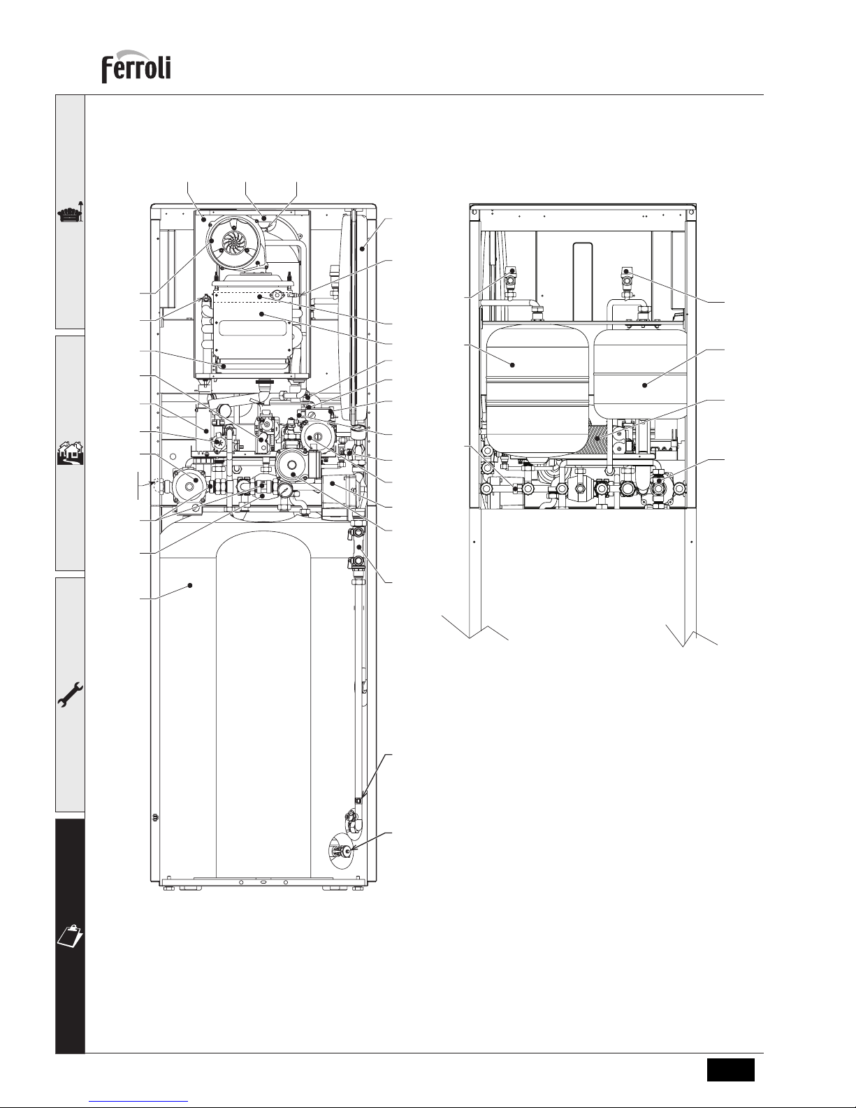
4.2 General view and main components
fig. 34 - Main components
5 29 191
56
82
188
22
161
14a
36
246
32
95
196
278
16
193
44
194
179
14b
14c
318a
315a
180
74
310
130
312
308
40
316
314
233
186
179
317a
319a
Page 31

ECONCEPT SOLAR ST
31EN
cod. -- - 11/2010 (Rev. 00)
4.3 Water circuit
fig. 35 - Water circuit
56
44
14a
32
11
10
7
95
241
246
36
186
161
278
16
196
145
179
179
194
193
154
97
191
233
155
130
311
309
310
Valvola regolazione
portata
314
313
180
321
316
315a
317a
319a
320
318a
40
322
323
8
179
14b
308
179
145
326
74
Indicatore di portata
14c
312
Page 32

ECONCEPT SOLAR ST
32 EN
cod. -- - 11/2010 (Rev. 00)
Key fig. 34-35-36
5 Sealed chamber
7 Gas inlet
8 Cold water inlet
10 System delivery
11 System return
14a Safety valve
14b Safety valve
14c Safety valve
16 Fan
22 Burner
29 Fume outlet manifold
32 Heating circulating pump
36 Automatic air vent
40 DHW expansion tank
44 Gas valve
56 Expansion tank
72 Room thermostat (not supplied)
72a Low temperature zone room thermostat (not
supplied)
74 System filling cock
82 Detection electrode
95 Diverter valve
97 Magnesium anode
130 Hot water tank circulating pump
138 External probe (not supplied)
139a Low temperature zone remote timer control (not
supplied)
145 Pressure gauge
154 Condensate outlet
155 Hot water tank temperature probe
161 Condensing heat exchanger
179 Non-return valve
180 Hot water tank
186 Return sensor
188 Ignition electrode
191 Fume temperature sensor
193 Trap
194 Exchanger
196 Condensate tray
233 Hot water tank drain cock
241 Bypass
246 Pressure transducer
256 Modulating heating circulating pump signal
278 Double sensor (Safety + Heating)
308 Solar expansion tank
309 Solar system filling cock
310 Solar system circulating pump
311 Collector temperature sensor
312 Flowmeter unit
313 Solar system drain cock
314 Solar return sensor
315a
Low temperature mixing valve
A = BROWN: FZ4B (9) - VALVE (6)
B = BLUE: FZ4B (10) - VALVE (2)
C = BLACK: FZ4B (11) - VALVE (3)
316 DHW mixing valve
317a Low temperature safety thermostat
318a Low temperature circulating pump
319a Low temperature modulation sensor
320 Low temperature delivery
321 Low temperature return
322 DHW recirculation return
323 Mixed DHW outlet
326 Solar system venting cock
Page 33

ECONCEPT SOLAR ST
33EN
cod. -- - 11/2010 (Rev. 00)
4.4 Technical data table
ECONCEPT SOLAR
ST 18
ECONCEPT SOLAR
ST 25
Data Unit Value Value
Max. heating capacity kW 18 25.2 (Q)
Min. heating capacity kW 3 5.3 (Q)
Max. Heat Output in heating (80/60°C) kW 17.7 24.6 (P)
Min. Heat Output in heating (80/60°C) kW 2.9 5.2 (P)
Max. Heat Output in heating (50/30°C) kW 19 26.6
Min. Heat Output in heating (50/30°C) kW 3.2 5.7
Max. heating capacity in hot water production kW 18 27
Min. heating capacity in hot water production kW 3 5.3
Max. Heat Output in hot water production kW 17.7 26.5
Min. Heat Output in hot water production kW 2.9 5.2
Efficiency Pmax (80-60°C) % 98.3 98.3
Efficiency Pmin (80-60°C) % 97.3 97.3
Efficiency Pmax (50-30°C) % 105.4 105.4
Efficiency Pmin (50-30°C) % 107.2 107.2
Efficiency 30% % 109.1 109.1
Efficiency class Directive 92/42 EEC NOx emission class - 5 5 (NOx)
Gas supply pressure G20 mbar 20 20
Max. gas delivery G20
m
3
/h
1.9 2.86
Min. gas delivery G20
m
3
/h
0.32 0.56
Gas supply pressure G31 mbar 37 37
Max. gas delivery G31 kg/h 1.41 2.11
Min. gas delivery G31 kg/h 0.23 0.41
Max. working pressure in heating bar 3 3 (PMS)
Min. working pressure in heating bar 0.8 0.8
Max. heating temperature °C 95 95 (tmax)
Heating water content litres 1 1.5
Heating expansion tank capacity litres 8 8
Heating expansion tank prefilling pressure bar 1 1
Max. working pressure in hot water production bar 9 9 (PMW)
Min. working pressure in hot water production bar 0.25 0.25
Hot water content litres 180 180
DHW circuit expansion tank capacity litres 12 12
DHW circuit expansion tank prefilling pressure bar 3 3
DHW flow rate 't 30°C
(flow rate obtained without supply of solar circuit)
l/
10min
230 260
DHW flow rate 't 30°C
(flow rate obtained without supply of solar circuit)
l/h 650 890 (D)
Solar expansion tank capacity litres 18 18
Protection rating IP X5D X5D
Power supply voltage V/Hz 230V/50Hz 230V/50Hz
Electrical power input W 280 280
Electrical power input in hot water production W 180 180
Empty weight kg 120 125
Type of unit C13-C23-C33-C43-C53-C63-C83-B23-B33
PIN CE 0461BT0920 0063BR3161
Page 34

ECONCEPT SOLAR ST
34 EN
cod. -- - 11/2010 (Rev. 00)
4.5 Diagrams
High Temperature zone circulating pumps Head/Pressure loss (ECONCEPT SOLAR ST 18)
A Boiler pressure losses
1 - 2 - 3 Circulating pump speed
Low Temperature zone circulating pumps Head/Pressure loss (ECONCEPT SOLAR ST 18)
B Boiler pressure losses
1 - 2 - 3 Circulating pump speed
0
1
2
3
4
5
6
7
0 500 1.000 1.500 2.000
Q [l/h]
H [m H
2
O]
A
3
2
1
0
1
2
3
4
5
6
7
0 500 1.000 1.500 2.000
Q [l/h]
H [m H
2
O]
B
3
2
1
Page 35

ECONCEPT SOLAR ST
35EN
cod. -- - 11/2010 (Rev. 00)
High Temperature zone circulating pumps Head/Pressure loss (ECONCEPT SOLAR ST 25)
A Boiler pressure losses
1 - 2 - 3 Circulating pump speed
Low Temperature zone circulating pumps Head/Pressure loss (ECONCEPT SOLAR ST 25)
B Boiler pressure losses
1 - 2 - 3 Circulating pump speed
0
1
2
3
4
5
6
7
0 500 1.000 1.500 2.000
Q [l/h]
H [m H
2
O]
3
2
1
A
0
1
2
3
4
5
6
7
0 500 1.000 1.500 2.000
Q [l/h]
H [m H
2
O]
B
3
2
1
Page 36

ECONCEPT SOLAR ST
36 EN
cod. -- - 11/2010 (Rev. 00)
4.6 Wiring diagram
fig. 36 - Wiring diagram
72 A
95
155
191
16
186
188
82
T°T°
278
139 A
138
DBM05D
DSP05
256
310
314
319a
318a
317a
DBM29
FZ4B
72
311
3.9 KOhm
32
16
44
NL
230V
50Hz
130
246
GND
OUT
+5V
123456
MODULDIRECT SENSOR
78
MIX
12345678910111213141516 17 18 19 20 21 22 23 24 25 26 27 28 29 30 31 32 33
315a
AB C
123456789101112
1110987654321
32121
Page 37

ECONCEPT SOLAR ST
37EN
cod. -- - 11/2010 (Rev. 00)
A
Attention: Before connecting the collector temperature sensor, remove the resistance between terminals 5
and 6 of controller DBM29.
A
Attention: Before connecting the room thermostat on the direct zone, remove the jumper on the terminal
block .
A
Attention: The boiler is arranged for operation with room thermostat on the low temperature zone. On connecting the remote timer control it will be necessary to configure the controller FZ4B. To do this, press the
AUTOCFG button (see fig. 37) until all the LEDs of theFZ4B card flash. The boiler will then be ready to operate
with remote timer control on the low temperature.
To reconnect the room thermostat in place of the remote timer control, carry out the above procedure again,
bringing the room thermostat to demand status (voltage-free contact).
fig. 37 - Controller FZ4B
AUTOCFG
OK
-
+
FZ4B
Page 38

ECONCEPT SOLAR ST
38 EN
cod. -- - 11/2010 (Rev. 00)
4.7 DBM29 (ECOTRONIC tech) - Solar Controller
User interface
fig. 38
1 Activated: solar collector temperature sufficient for exchange, normal operation
Flashing: solar collector cold recognition
2 Activated: solar collector antifreeze function
3 Activated: shutter closed for hot water tank max. temperature reached
Deactivated: shutter open, normal operation
4 Activated: solar collector temperature ok, normal operation
Flashing: solar collector cooling on
5 Solar circulating pump on
6 Boiler in DHW mode
7 Boiler in heating mode
8 Solar card fault
9 Boiler burner on
11 Upper hot water tank / solar collector return temperature
12 Hot water tank / solar collector temperature
13 Activated: Solar collector temperature ok, normal operation
Deactivated: solar collector temperature sensor fault
Flashing: solar collector limit temperature function
14 Activated: solar collector return temperature ok, normal operation
Deactivated: solar collector return temperature sensor fault
15 Activated: boiler hot water tank temperature correct, normal operation
Flashing: hot water tank cooling function
16 Actual solar circulating pump speed (A=Min., E=Max.)
21 Solar collector temperature sensor info
22 Solar collector return temperature sensor info
23 Activated: excess heat elimination/supplementary heating demand
Deactivated: no excess heat elimination/supplementary heating demand
A ON/OFF / Enter button
B Parameter selection button
C Parameter selection button
D Service menu access / information button
12
11
23167
13
AB CD
1
2
3
4
14
5
15
621 22 9
8
Page 39
ECONCEPT SOLAR ST
39EN
cod. -- - 11/2010 (Rev. 00)
Lighting
Whenever the power to the regulator is switched on, the display activates all the symbols for 2 seconds; in the next 5
seconds, the display will show the regulator software version.
Standby mode
After the lighting stage, if there are no faults and/or higher priority demands, the regulator goes to standby mode. The
following information is displayed:
• Standby: temperature of Solar Collector PT1000 sensor S3 with range 1¸175°C, the symbol S3 will be lit up; tem-
perature of Solar collector Return NTC sensor S4 with range 1¸125°C, the symbol S4 will be lit up.
• Press the Info button for 1 second and the regulator returns to standby mode.
Operation
Solar Circulating Pump activation
If the temperature of the Hot Water Tank Sensor is lower than the Tank max. temperature parameter value (Installer
parameter, default value equal to 60°C) and if the difference (positive) between the temperature of Solar Collector Sensor S3 and the temperature of the Hot Water Tank Sensor is higher than or equal to the Activation temperature differential parameter value (Installer parameter, default value equal to 6°C) then the ECOTRONIC tech regulator activates
the Solar Circulating Pump .
To signal this mode, the Solar Circulating Pump symbol will be lit up.
Solar Circulating Pump modulation
When the Solar Circulating Pump is working and the Solar Circulating Pump Operation parameter (Installer parameter,
default value equal to 0=On/Off ) is set to 1, the modulation algorithm is:
1. If the difference between the temperature of Solar Collector Sensor S3 and Solar Collector Return Sensor S4 is less
than or equal to the Minimum - Solar Circulating Pump Modulation temperature differential parameter value (Installer
parameter, default value equal to 10°C), the Solar Circulating Pump works at speed 1 (Min. power, 40%). To signal
this mode, the symbol A will be lit up.
2. If the difference between the temperature of Solar Collector Sensor S3 and the Solar Collector Return Sensor S4 is
greater than the Minimum - Solar Circulating Pump Modulation temperature differential parameter value (Installer
parameter, default value equal to 10°C), the Solar Circulating Pump works at speed 2 (55%). To signal this mode,
the symbol B will be lit up
3. If the difference between the temperature of Solar Collector Sensor S3 and the Solar Collector Return Sensor S4 is
greater than the Minimum - Solar Circulating Pump Modulation temperature differential parameter value (Installer
parameter, default value equal to 10°C) plus the Solar Circulating Pump modulation temperature differential parameter value (Installer parameter, default value equal to 5°C), the Solar Circulating Pump works at speed 3 (70%). To
signal this mode, the symbol C will be lit up.
4. If the difference between the temperature of Solar Collector Sensor S3 and the Solar Collector Return Sensor S4 is
greater than the Minimum - Solar Circulating Pump Modulation temperature differential parameter value (Installer
parameter, default value equal to 10°C) plus double the Solar Circulating Pump Modulation temperature differential
parameter value (Installer parameter, default value equal to 5°C), the Solar Circulating Pump works at speed 4
(85%). To signal this mode, the symbol D will be lit up.
5. If the difference between the temperature of Solar Collector Sensor S3 and the Solar Collector Return Sensor S4 is
greater than the Minimum - Solar Circulating Pump Modulation temperature differential parameter value (Installer
parameter, default value equal to 10°C) plus triple the Solar Circulating Pump Modulation temperature differential
parameter value (Installer parameter, default value equal to 5°C), the Solar Circulating Pump works at speed 5 (Max.
power , 100%). To signal this mode, the symbol E will be lit up.
N.B.: If, at the moment of Solar Circulating Pump activation, the ECOTRONIC tech regulator does not have to set
speed 5 (Max. power , 100%), the Solar Circulating Pump will work in any case at speed 5 (Max. power, 100%)
in the first second of operation .
If the Solar Circulating Pump Operation parameter (Installer parameter , default value equal to 1=Modulating)
is set to 0 there will be no modulation: the Solar Circulating Pump will work in on/off mode according to the
normal Solar Circulating Pump activation/deactivation algorithms . To signal this mode, the symbol E will al-
ways be lit up.
Page 40

ECONCEPT SOLAR ST
40 EN
cod. -- - 11/2010 (Rev. 00)
Solar Circulating Pump deactivation
If the temperature of the Hot Water Tank Sensor is lower than the Tank max. temperature parameter (Installer parameter, default value equal to 60°C) and if the difference (positive) between the temperature of Solar Collector Sensor S3
and the temperature of Solar Collector Return Sensor S4 is less than or equal to the Deactivation temperature differential parameter value (Installer parameter , default value equal to 4°C) then the ECOTRONIC tech regulator deactivates
the Solar Circulating Pump.
If the temperature of the Hot Water Tank Sensor is higher than or equal to the Tank max. temperature parameter value (Installer parameter , default value equal to 60°C) then the ECOTRONIC tech regulator deactivates the Solar Circulating Pump.
To signal this mode, the Solar Circulating Pump symbol will be deactivated.
Off mode
If there are no faults, it is always possible to press the ON/OFF button for 3 seconds to switch the regulator to Off mode
. All demands are terminated, the shutter will be closed and the display shows the message OFF .
Only the Antifreeze protection and the Circulating Pump anti-shutdown remain active . To return the system to an operating mode, press the ON/OFF button again for 3 seconds .
FH mode
If there are no faults it is always possible to press the button ¯ for 10 seconds to switch the regulator to FH mode. The
FH mode lasts 10 minutes: during this time, the Solar Circulating Pump will be activated at speed 5 (Max. power, 100%)
and deactivated every 10 seconds; to signal this mode the display will indicate FH and the Solar Circulating Pump symbol and the symbol E will light up and go off every 10 seconds . The FH mode can be terminated by switching the regulator to Off mode and then to ON mode .
Flow limiter adjustment mode
If there are no faults, it is always possible to press the button - for 10 seconds to switch the regulator to Flow Limiter
Adjustment mode .
To signal the Flow Limiter Adjustment mode, the Radiator and Tap symbols will start flashing together . The Solar Circulating Pump is immediately activated in continuous mode and at speed 5 (Max. power, 100%) .
The Flow Limiter Adjustment mode ends automatically after 2 minutes or by pressing the button for 10 seconds.
System Cooling function (Collector and Hot Water Tank)
This function depends on the System cooling parameter value (Installer parameter, default value equal to 1=On) .
During normal operation, if the temperature of the Hot Water Tank Sensor is higher than the Tank max. temperature parameter value (Installer parameter, default value equal to 60°C) and lower than the Hot water tank limit temperature parameter value (Installer parameter , default value equal to 80°C) and if the temperature of Solar Collector Sensor S3 is
higher than the System Cooling function activation collector temperature parameter value (Installer parameter , default
value equal to 120°C) then the ECOTRONIC tech regulator activates the Solar Circulating Pump to cool the collector .
To signal this mode, the Solar Panel symbol will start flashing .
The function ends when the temperature of Solar Collector Sensor S3 becomes lower than the System Cooling function
activation collector temperature parameter value (Installer parameter, default value equal to 120°C) - 2°C.
During normal operation, if the temperature of the Hot Water Tank Sensor is higher than the Tank max. temperature
parameter value (Installer parameter, default value equal to 60°C) and lower than the Hot water tank limit temperature
parameter value (Installer parameter , default value equal to 80°C) and if the temperature of Solar Collector Sensor S3
is lower than the Tank max. temperature parameter value (Installer parameter, default value equal to 60°C) - 5°C then
the ECOTRONIC tech regulator activates the Solar Circulating Pump to cool the hot water tank.
To signal this mode, the Hot Water Tank symbol will start flashing .
The function ends when the temperature of Solar Collector Sensor S3 becomes higher than the Tank max. temperature
parameter value (Installer parameter, default value equal to 60°C) - 2°C.
Page 41
ECONCEPT SOLAR ST
41EN
cod. -- - 11/2010 (Rev. 00)
Hot Water Tank Cooling function (solar collector overheating prevention)
This function depends on the Tank cooling parameter value (Installer parameter, default value equal to 0=Off); also, if
the System Cooling function is active (Collector and Hot Water Tank), the latter has priority over the Hot Water Tank
Cooling Function .
During normal operation, if the temperature of the Hot Water Tank Sensor is higher than the Tank max. temperature
parameter value (Installer parameter, default value equal to 60°C) and lower than the Hot water tank limit temperature
parameter value (Installer parameter , default value equal to 80°C) then the ECOTRONIC tech regulator leaves the Solar Circulating Pump on to prevent overheating of the solar collector.
If the temperature of the Hot Water Tank Sensor becomes higher than or equal to the Hot water tank limit temperature
parameter value (Installer parameter , default value equal to 80°C) and if the temperature of Solar Collector Sensor S3
is lower than the Hot water tank limit temperature (Installer parameter, default value equal to 80°C) – 5°C then the ECOTRONIC tech regulator activates the Solar Circulating Pump to cool the hot water tank.
To signal this mode, the Hot Water Tank symbol will start flashing .
Hot Water Tank Limit Temperature function
The Solar Circulating Pump will be deactivated if the temperature of the Hot Water Tank Sensor becomes higher than or equal
to the Hot water tank limit temperature parameter value (Installer parameter, default value equal to 80°C); in this case, as well
as shutting down the Solar Circulating Pump, the ECOTRONIC tech regulator must also close the shutter .
To signal this mode, the Solar Circulating Pump symbol will go off, and the Shutter symbol will be lit up.
The function ends when the temperature of the Hot Water Tank Sensor becomes lower than the Hot water tank limit
temperature parameter value (Installer parameter, default value equal to 80°C) – 2°C.
Solar Collector Limit Temperature function
The Solar Circulating Pump will be deactivated if the temperature of Solar Collector Sensor S3 becomes higher than or
equal to the Collector limit temperature parameter value (Installer parameter, default value equal to 140°C); in this case,
as well as shutting down the Solar Circulating Pump, the ECOTRONIC tech regulator must also close the shutter .
To signal this mode, the Solar Circulating Pump symbol will be off, the Shutter symbol lights up and the symbol S3 above
the collector will start flashing .
The function ends when the temperature of Solar Collector Sensor S3 becomes lower than the Collector limit temperature parameter value (Installer parameter, default value equal to 140°C) - 2°C.
Solar Collector Cold recognition function
This function depends on the Collector minimum limit parameter value (Installer parameter, default value equal to 0=Off).
During normal operation, if the temperature of Solar Collector Sensor S3 is lower than the Collector minimum temperature parameter value (Installer parameter, default value equal to 10°C) then the ECOTRONIC tech regulator will deactivate the Solar Circulating Pump.
To signal this mode, the Sun symbol will start flashing.
The function ends when the temperature of Solar Collector Sensor S3 becomes higher than the Collector minimum temperature parameter value (Installer parameter, default value equal to 10°C) + 2°C.
Solar Collector Antifreeze function
This function depends on the Antifreeze protection function parameter value (Installer parameter, default value equal to 0=Off).
During normal operation, if the temperature of Solar Collector Sensor S3 is lower than the Antifreeze temperature (Installer
parameter , default value equal to 4°C), the Solar Circulating Pump will be activated as long as the temperature of Solar Collector Sensor S3 is higher than the Antifreeze temperature (Installer parameter , default value equal to 4°C) + 1°C.
Solar Circulating Pump Anti-shutdown function
After 24 hours of inactivity, the Solar Circulating Pump is activated for 3 seconds .
Page 42

ECONCEPT SOLAR ST
42 EN
cod. -- - 11/2010 (Rev. 00)
FAULTS
LCD display off
Make sure the regulator is powered: using a digital multimeter, check the presence of voltage at terminals 24 and 25 .
In case of no voltage, check the wiring.
In case of sufficient voltage (Range 195 – 253 Vac), check the fuse. The fuse is located inside the regulator : to access
it, follow steps 1 and 2 of the section "Accessing internal terminal blocks".
LCD display on
Any operation error conditions are shown on the regulator LCD display .
Fault 82 - Regulator configuration fault
Make sure parameter P26 is set to “0”.
Fault 83 - Solar Collector PT1000 Sensor S3 faulty
The fault, understood as a short circuit or open circuit, of the sensor causes deactivation of the Solar Circulating Pump
and shutter closing . On eliminating the fault, the protection is immediately deactivated .
To signal this fault, the symbol S3 will be deactivated whereas the Fault symbol, the symbol S3 and the backlight will
start flashing .
Fault 84 - Solar Collector Return NTC Sensor S4 faulty
The fault, understood as a short circuit or open circuit, of the sensor does not cause deactivation of the Solar Circulating
Pump . The system must simply work as though the Basic System were set . On eliminating the fault, the protection is
immediately deactivated.
To signal this fault, the symbol S4 will be deactivated whereas the Fault symbol, the symbol S4 and the backlight will
start flashing .
Fault 85 - Boiler card communication fault
Make sure parameter P26 is set to “0”.
Fault 87 - Protection for no circulation
Only with FLOWMETER ENABLED
This fault is activated when, with the Solar Pump activated, the card does not detect flow in the solar circuit for 10 consecutive minutes . The fault causes deactivation of the Solar Pump. After checking and eliminating the fault, the protection can be removed, activating and deactivating the Off mode .
Make sure parameter P25 is correctly set.
Fault code Card Description Fault
F82 Regulator configuration fault
F83 Solar Collector PT1000 Sensor S3
F84 Solar Collector Return NTC Sensor S4
F85 Boiler card communication fault
F87 Protection for no circulation
Page 43
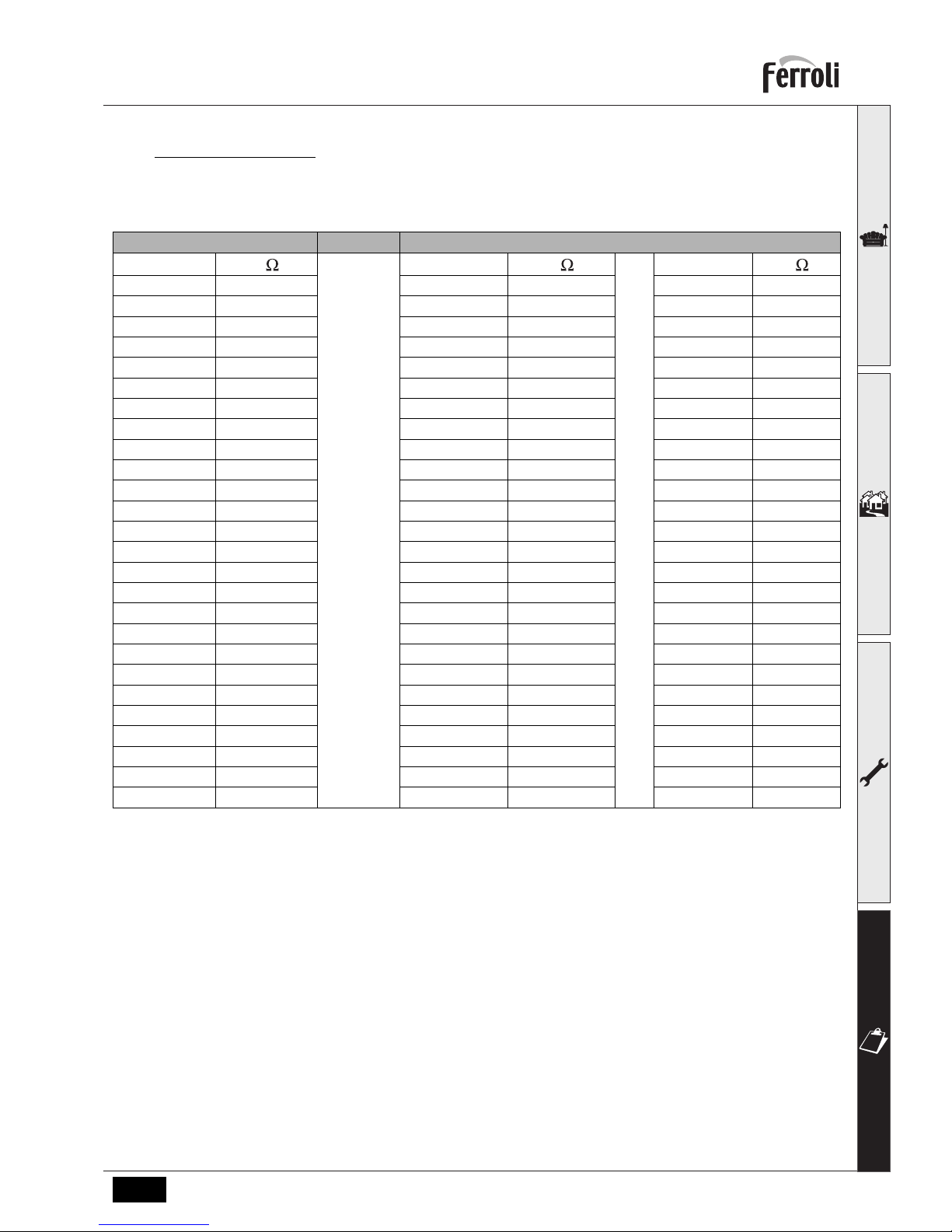
ECONCEPT SOLAR ST
43EN
cod. -- - 11/2010 (Rev. 00)
Sensor characteristics
The temperature sensors can be checked with a digital multimeter : disconnect the sensor from regulator and check
correspondence with the following tables .
NTC PT 1000
T(°C)
R ( )
T(°C)
R ( )
T(°C)
R ( )
-10 54932 -10 961.5 120 1462
-5 42080 -5 980.75 125 1481.25
0 32505 0 1000 130 1500.5
5 25308 5 1019.25 135 1519.75
10 19854 10 1038.5 140 1539
15 15689 15 1057.75 145 1558.25
20 12483 20 1077 150 1577.5
25 9999 25 1096.25 155 1596.75
30 8060 30 1115.5 160 1616
35 6537 35 1134.75 165 1635.25
40 5332 40 1154 170 1654.5
45 4374 45 1173.25 175 1673.75
50 3608 50 1192.5 180 1693
55 2991 55 1211.75 185 1712.25
60 2492 60 1231 190 1731.5
65 2086 65 1250.25
195 1750.75
70 1754 70 1269.5 200 1770
75 1481 75 1288.75
80 1257 80 1308
85 1070 85 1327.25
90 915 90 1346.5
95 785 95 1365.75
100 677 100 1385
105 585 105 1404.25
110 507 110 1423.5
115 442 115 1442.75
Page 44

ECONCEPT SOLAR ST
44 EN
cod. -- - 11/2010 (Rev. 00)
SERVICE MENU
The regulator Service Menu is accessed by pressing the Info button for 10 seconds . Press the Up/Down buttons to
select “tS”, “In”, “Hi” or “rE” . tS" means Transparent Parameters Menu, "In" Information Menu, "Hi" History Menu, and
"rE" History Menu Reset. After selecting the Menu, press the Info button to access it .
“tS” - Transparent Parameters Menu
The regulator has 26 editable transparent parameters:
Press the Up/Down buttons to scroll the list of parameters, in increasing or decreasing order respectively. To modify the
value of a parameter just press the Enter button in relation to the parameter, then edit it with the Up/Down buttons: the
change will be automatically saved.
Press the Enter button to return to the list of parameters .
Press the Info button to return to the Service Menu . Press the Info button for 10 seconds to exit the regulator Service
Menu or exiting is automatic after 15 minutes .
Sch. Description of Transparent Parameters Range Default
P01 System layout setting
(DO NOT MODIFY)
0-3 1
P02 Activation temperature differential (°C) 1-20°C 6°C
P03 Deactivation temperature differential (°C) 1-20°C 4°C
P04 Tank max. temperature (°C) 20-95°C 60°C
P05 Collector limit temperature (°C) 110-160°C 140°C
P06 System cooling parameter (0=Off, 1=On) 0-1 1=On
P07 System cooling function activation collector temperature (°C) 100-150°C 120°C
P08 Collector min. limitation parameter (0=Off, 1=On) 0-1 0=Off
P09 Collector min. temperature (°C) 10-90°C 10°C
P10 Antifreeze protection function parameter (0=Off, 1=On) 0-1 0=Off
P11 Antifreeze temperature (°C) 1-10°C 4°C
P12 Tank cooling parameter (0=Off, 1=On) 0-1 0=Off
P13 Thermostat activation temperature (°C) 0-95°C 40°C
P14 Thermostat deactivation temperature (°C) 0-95°C 45°C
P15 Thermal quantity balance parameter (0=Off, 1=On) 0-1 0=Off
P16 Solar circuit max. flow rate (l/min) 0-20 6 l/min
P17 Not implemented 00
P18 Antifreeze liquid protection rating (%) 0-50 % 25 %
P19 Solar Circulating Pump output operation mode (0=OFF continuous, 1=auto and 2=ON continu-
ous)
0-2 1=Auto
P20 FREE CONTACT relay operation mode
(0=OFF continuous, 1=auto, 2=ON continuous,
3=Boiler activation/deactivation)
0-3 1=Auto
P21 Minimum - Solar Circulating Pump
modulation temperature differential (°C)
5-20°C 10°C
P22 Solar Circulating Pump modulation temperature differential (°C) 2-20°C 5°C
P23 Solar Circulating Pump operation (0=On/Off, 1=Modulating) 0-1 1
P24 Hot water tank limit temperature (°C) 70-95°C 80°C
P25 Flowmeter type selection (0=Operation without flowmeter , 1=DN8, 2=DN10, 3=DN15,
4=DN20, 5=DN25)
0-5 0
P26 Operation type selection (0=Communicating, 1=Stand alone) 0-1 0
Page 45

ECONCEPT SOLAR ST
45EN
cod. -- - 11/2010 (Rev. 00)
“In” - Information Menu
The regulator can display the following information:
Press the Up/Down buttons to scroll the list of information. To display the value just press the Enter button in relation to
the parameter . In case of damaged Sensor, the regulator displays hyphens .
Press the Enter button to return to the list of information .
Press the Info button to return to the Service Menu . Press the Info button for 10 seconds to exit the regulator Service
Menu or exiting is automatic after 15 minutes .
“Hi” - History Menu
The microprocessor can memorise the total hours with regulator fed (Ht), the last 10 boiler faults and other information
; the History datum item H1: represents the most recent fault that occurred; the History datum item H10: represents the
least recent fault that occurred.
Press the Up/Down buttons to scroll the list of faults . To display the value press the Enter button in relation to the parameter .
Press the Enter button to return to the list of faults .
Press the Info button to return to the Service Menu . Press the Info button for 10 seconds to exit the card Service Menu
or exiting is automatic after 15 minutes .
t01 S1: PT1000 sensor - Not used (°C) --
t02 S2: Hot water tank NTC sensor (°C)
Only with parameter P26=1, Stand alone
--
t03 S3: Solar collector PT1000 sensor (°C) between 01 and 175°C
t04 S4: Solar Return Collector NTC sensor (°C) between 01 and 125°C
F05 Solar circuit flow rate (Lt_min)Only with Flowmeter connected and activated 00-99 Lt_min
P06 Actual modulating circulating pump speed (40%=Speed 1¸ 100%=Speed 5) 0-100%
Ht No. hours ECOTRONIC Tech operation (Supply) between 0 and 9999 hours
H01 Fault code
H02 Fault code
H03 Fault code
H04 Fault code
H05 Fault code
H06 Fault code
H07 Fault code
H08 Fault code
H09 Fault code
H10 Fault code
H11 No. hours Solar Circulating Pump operation between 0 and 9999 hours
H12 No. hours AUX1 output relay operation between 0 and 9999 hours
H13 No. hours AUX2 output relay operation between 0 and 9999 hours
H14 No. hours FREE CONTACT output relay operation between 0 and 9999 hours
H15 Max. temp. S1: PT1000 sensor Not used (°C) --
H16 Max. temp. S2: Hot water tank NTC sensor (°C) Only with parameter P26=1, Stand alone --
H17 Max. temp. S3: Solar Collector PT1000 sensor (°C) between 01 and 175°C
H18 Max. temp. S4: Solar Return Collector NTC sensor (°C) between 01 and 125°C
H19 No. litres solar circuit (litres)Only with Flowmeter connected and activated between 0 and 9999 litres
H20 Average circulating pump speed (%)Cumulative calculation performed only if the circulating
pump is working
0-100%
BIL Thermal quantity balance (KWh)Cumulative calculation performed only if the circulating pump
is working
between 0 and 9999 kWh
Page 46

ECONCEPT SOLAR ST
46 EN
cod. -- - 11/2010 (Rev. 00)
“rE” - History Reset
Press the ON/OFF button for 3 seconds to delete all the information stored in the History Menu : the card will automatically exit the Service Menu, in order to confirm the operation.
Press the Info button for 10 seconds to exit the card Service Menu or exiting is automatic after 15 minutes .
THERMAL QUANTITY BALANCE (CALCULATION)
The Regulator performs the accumulated energy calculation only if the Solar Circulating Pump is working : the value is
then displayed through the parameter BIL in the History menu, see Service Menu section.
B
This function depends on the value of parameter P15 Thermal Quantity Balance (Installer parameter, default
value equal to 0=Off) which must be set to 1 .
NON-MODULATING CIRCULATING PUMP (WITHOUT FLOWMETER)
The value of the following parameters must be correctly set:
• P16 Solar circuit max. flow rate (l/min)
• P18 Antifreeze liquid protection rating (%)
• P23 Solar circulating pump operation (0=On/Off)
Accumulated energy (kWh) =
Value P16 * 60 x (deltaT: S3 – S4) x 1,163 x ((100-Value P18)/100) / 1000
MODULATING CIRCULATING PUMP (WITH FLOWMETER)
The value of the following parameters must be correctly set:
• P18 Antifreeze liquid protection rating (%)
• P23 Solar Circulating Pump operation (1=Modulating)
• P25 Flowmeter type selection
Accumulated energy (kWh) =
Value measured by flowmeter *60 x (delta T:S3-S4) x 1,163 x ((100-valueP18)/100)/1000
N.B.: The regulator performs the instantaneous calculation every second and updates the value of parameter BIL
every time the accumulated energy increases by 1kW .
In case of a power failure, the Regulator does not lose the accumulated energy calculation : the data is saved
once every 10 minutes, therefore when the power is restored and the solar circulating pump restarts, the cal-
culation can begin again without loss of data .
Page 47

ECONCEPT SOLAR ST
47EN
cod. -- - 11/2010 (Rev. 00)
4.8 FZ4B low temperature zone card
Service Menu
Press the Ok button for 5 seconds to access the zone controller Service Menu.
Press the buttons and to select:
"tS" = Transparent Parameters Menu
"In" = Information Menu
"Hi" = History Menu (of the zone controller)
"rE" = History Menu Reset (of the zone controller).
After selecting the Menu, press the Ok button to access it.
“tS” - Transparent Parameters Menu
The zone controller is provided with 35 transparent parameters also modifiable from Remote Control (Service Menu):
Press the "+" and "-" buttons to scroll the list of parameters in increasing or decreasing order respectively. To modify
the value of a parameter, press the Ok button after selecting it: press the + and - buttons to modify it, and the setting
will be automatically saved. Press the Ok button to return to the list of parameters. Press the Ok button for 3 seconds
to return to the Service Menu. Press the Ok button for 5 seconds to exit the Service Menu.
Remote
Control
Zone Card
FZ4B
Boiler Card
(if prearranged)
Description
transparent parameters
Range
Default
(for mixed
zone)
Recommended for
Direct Zone
01 P01 Zone1 Min. Temperature 10-90°C 10°C 10°C
02 P02 Zone1 Max. Temperature 10-90°C 40°C 70÷80°C
03 P03 Zone1 calculated set point offset 0-40°C 10°C 0°C
04 P04 Do not modify 10-90°C 90°C
05 P05 o01 Zone1 External Probe Curve 0-10 0
06 P06 o02 Zone1 External Probe Offset 20-40°C 30°C
07 P07 Zone2 Min. Temperature 10-90°C 10°C
08 P08 Zone2 Max. Temperature 10-90°C 80°C
09 P09 Zone2 calculated set point offset 0-40°C 0°C
10 P10 DO NOT MODIFY 10-90°C 90°C
11 P11 o03 Zone2 External Probe Curve 0-10 0
12 P12 o04 Zone2 External Probe Offset 20-40°C 30°C
13 P13 Zone3 Min. Temperature 10-90°C 10°C
14 P14 Zone3 Max. Temperature 10-90°C 80°C
15 P15 Zone3 calculated set point offset 0-40°C 0°C
16 P16 DO NOT MODIFY 10-90°C 90°C
17 P17 o05 Zone3 External Probe Curve 0-10 0
18 P18 o06 Zone3 External Probe Offset 20-40°C 30°C
19 P19 Mixing valve on+off time 0-15sec 15sec
20 P20 Mixing valve boost 0-120sec 0sec
21 P21 Mixing valve on time for °C 0-15sec/°C 1sec/°C
22 P22 DO NOT MODIFY 0-20°C 4°C
23 P23 DO NOT MODIFY 70-85°C 80°C
24 P24 DO NOT MODIFY 0-60°C 0°C
25 P25 DO NOT MODIFY 0-1 0
26 P26 DO NOT MODIFY 10-65° 55°C
27 P27 Post-circulation time 0-20 min 10 min
28 P28 DO NOT MODIFY 0-1 0
29 P29 Delay for Zone 0-255 sec. 30 sec.
30 P30 DO NOT MODIFY 0-1 0
31 P31 DO NOT MODIFY 0-3 min 3 min
32 P32 DO NOT MODIFY 0-10°C 5°C
33 P33 DO NOT MODIFY 0-10 min 2 min
34 P34 DO NOT MODIFY 0-1 0
35 P35 DO NOT MODIFY 0-1 0
Page 48

ECONCEPT SOLAR ST
48 EN
cod. -- - 11/2010 (Rev. 00)
Description of parameters
The "Min. Zone Temperature" and "Max. Zone Temperature" parameters define the delivery temperature adjustment
range for each zone; in case of Remote Control, the user delivery temperature adjustment will come within this range
and be modulated by the Remote Control during operation; in case of Chronothermostat: on closing of the contact, the
delivery temperature adjustment will be set to the "Max. Zone Temperature" parameter value; on closing of the contact,
the demand will be eliminated. The "Zone calculated set point offset" parameter defines an offset for the required delivery temperature set point. Example: if the Remote Control demands 52°C and this parameter is set to 10°C, the zone
controller will demand 62°C from the boiler; in case of Chronothermostat, this value will be added to the "Max. Zone
Temperature" parameter. The "Zone External Probe Curve" and "Zone External Probe Offset" parameters are used for
the sliding temperature in case of Chronothermostat.
fig. 39 - Compensation curves
fig. 40 - Example of parallel compensation curve shift
The "Mixing valve on+off time" and "Mixing valve on time for °C" parameters are used for adjustment of the mixing valve.
Example: with the parameters set to the default value (therefore 15sec and 1sec/°C), if the delivery temperature required for the mixed zone is 32°C and the actual delivery temperature measured by the mixed zone sensor is 28°C, the
mixing valve will remain in opening 4sec (=(32°C-28°C)*1sec/°C) every 15sec. The same rule (in absolute value) is applied for closing.
The "Mixing Valve Boost" parameter defines the mixing valve forced opening time. With every new demand, the mixing
valve is opened for this time, before starting adjustment.
The "Post-circulation time" parameter defines the post-circulation time and is activated on the last zone which ends the
temperature demand.
The "Delay for Zone Valves" parameter defines a waiting time between the zone controller demand and activation of
the boiler circulating pump.
20
30
40
50
60
70
80
90
85
20 10 0 -10 -20
1
2
3
4
5
68910 7
20
30
40
50
60
70
80
90
85
20 10 0 -10 -20
1
2
3
4
5
6
8910
7
20 10 0 -10 -20
20
30
40
50
60
70
80
90
85
1
2
3
4
568910 7
OFFSET = 20 OFFSET = 40
Page 49

ECONCEPT SOLAR ST
49EN
cod. -- - 11/2010 (Rev. 00)
"In" - Information Menu
The card can display the following information:
Press the + and - buttons to scroll the list of information in increasing or decreasing order respectively. To display the
value of a parameter, press the Ok button after selecting it: in case of damaged sensor, the card displays hyphens.
Press the Ok button again to return to the list of parameters. Press the Ok button for 3 seconds to return to the Service
Menu. Press the Ok button for 5 seconds to exit the Service Menu.
"Hi" - History Menu
The card can store the last 10 faults: the History datum item H1: represents the most recent fault that occurred; the
History datum item H10: represents the least recent fault that occurred.
The codes of the faults saved are also displayed on the corresponding menu of the Remote Control.
Press the + and - buttons to scroll the list of faults. To display the value of a parameter, press the Ok button after selecting it.
Press the Ok button for 3 seconds to return to the Service Menu. Press the Ok button for 5 seconds to exit the Service Menu.
"rE" - History Reset
Press the Ok button for 3 seconds to delete all the faults stored in the History Menu: the card will automatically exit the
Service Menu, in order to confirm the operation.
Press the Ok button for 3 seconds to return to the Service Menu.
Information during operation
The controller indicates the boiler operating mode and its faults through the incorporated display: "St" means Standby
(no demand in progress), "CH" means that the zone controller requests the boiler for activation of heating mode, "DH"
means Domestic Hot Water production. The fault codes are given below:
The fault codes are also displayed on the corresponding menu of the Remote Control during normal operation.
t01 NTC sensor (T1) between 05 and 125°C
t02 NTC sensor (T2) between 05 and 125°C
t03 NTC sensor (T3) between 05 and 125°C
t04 NTC sensor (T4) between -30 and 70°C (Negative values flash)
t05 Remote Control (RT1) or On/Off Thermostat demand On/Of
t06 Remote Control (RT2) or On/Off Thermostat demand On/Of
t07 Remote Control (RT3) or On/Off Thermostat demand On/Of
t08 Zone 1 Heating set point (Calculation) between 05 and 125°C
t09 Zone 2 Heating set point (Calculation) between 05 and 125°C
t10 Zone 3 Heating set point (Calculation) between 05 and 125°C
t11 Zone Card Heating set point (Calculation) between 05 and 125°C
Fault
code
Possible cause Cure
F70 NTC sensor fault (T1) With circuit / contact open
F71 NTC sensor fault (T2) With circuit / contact open
F72 NTC sensor fault (T3) With circuit / contact open
F73 NTC sensor fault (T4) With circuit / contact open
F74 Communication with boiler card not present
F75 Communication with Remote Control (RT1) not present (Only with Remote Control connected)
F76 Communication with Remote Control (RT2) not present (Only with Remote Control connected)
F77 Communication with Remote Control (RT3) not present (Only with Remote Control connected)
Page 50

ECONCEPT SOLAR ST
50 EN
cod. -- - 11/2010 (Rev. 00)
User settings
The settings for Heating, such as max. delivery temperature, external probe curve (with optional external probe connected to boiler), weekly time programming, etc., are independent for each zone; these are modified through the Remote Control of the corresponding temperature zone. In case of direct zones, make sure to set a similar max. delivery
temperature for all the temperature zones. With Room Chronothermostats, on closing of the contact the delivery temperature is adjusted to the max. value set by the zone controller. The settings relevant to DHW such as Domestic Hot
Water temperature, weekly time programming (with boiler prearranged: see relevant documentation), etc., are managed
in parallel; these are modified through the temperature zone Remote Controls. In case of DHW weekly time programming, the zone controller overlaps programmes coming from the single Remote Controls.
Conversion of low temperature zone to high temperature zone
The low temperature zone can become a high temperature zone. Follow the instructions given below (also refer to the
table of parameters FZ4B):
1. Parameter 2 card FZ4B 40°C to 70°C ÷ 80°C
2. Parameter 3 card FZ4B 10°C to 0°C
3. Disconnect the safety thermostat (317A) from the delivery pipe.
4. Do not disconnect or bypass the mixing valve (ref. 315a)
Page 51

Page 52

FERROLI S.p.A.
Via Ritonda 78/a
37047 San Bonifacio - Verona - ITALY
www.ferroli.it
 Loading...