

Page 1
Ferm BV • P.O. Box 134 • 8280 AC Genemuiden • NL • www.ferm.com 0210/25
Ferm Bench Morticer
FBM-370
USER’S MANUAL
Art.nr. 733600
Screwfix Art.nr. 18914
UK Subject to change
Document Ref:
FBM-370/18914/PMR26/Issue 1/April 02
Copyright ©
These instructions are the sole property of Ferm-Omega Tools and may not be reproduced
Page 2
FERM TABLE BENCH MORTICER
FBM-370
USERS MANUAL
TECHNICAL SPECIFICATIONS
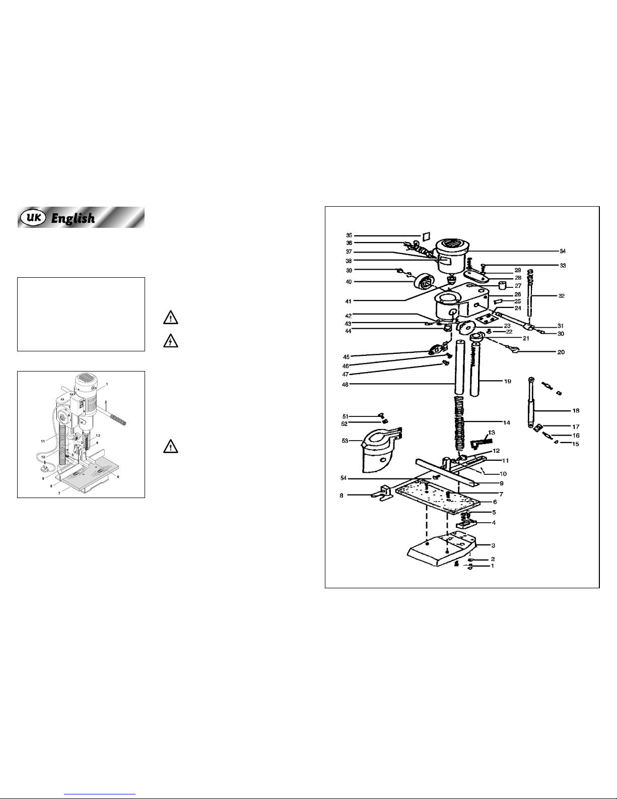
PRODUCT INFORMATION
1. Machine head
2. Handle
3. Depth set guide
4. Chisel and bit
5. Fence clamping lever
6. Hold down clamp
7. Fence
8. Table
9. Bracket
10. Gear column
11. Guide column
12. Protection guard
PACKAGE CONTENTS
1 Mortising machine
1 3/4" Chisel Bush
1 Allen key 5 mm
1 Allen key 6 mm
1 Mortise chisel set 13mm
1 Chuck key
1 Arbor
1 Chuck
Check the machine, loose parts and accessories for
transport damage.
SAFETY INSTRUCTIONS
The following symbols are used in these instructions for
use:
Denotes risk of personal injury, loss of life or
damage to the tool in case of non-observance of the
instructions in this manual.
Denotes risk of electric shock.
Carefully read this manual before using the machine.
Make sure that you know how the machine functions and
how to operate it. Maintain the machine in accordance
with the instructions to make sure it functions properly.
Keep this manual and the enclosed documentation with
the machine.
Ferm products are manufactured to high quality standards they are safe and fit for purpose at time of sale, but
all tools can be dangerous if the correct precautions are
not taken. Always follow these instructions, do not carry
out the operation until you are sure you can do so in safety. Remember consider the work environment for safe
operation as well as safety for tool use.
Warning! When using electric tools, basic safety
precautions should always be followed to reduce
the risk of fire, electric shock and personal injury. Read all
these instructions before attempting to operate this product.
Save these instructions for future reference.
Voltage | 230 V~
Frequency | 50 Hz
Power input | 450 W
IP-code | IP40
Speed, no load | 2800/min
Mortising capacity | 13 mm
Max. drilling capacity | 16 mm
Max. chisel travel | 115 mm
Nett weight | 25 kg
Lpa (sound pressure) | 72.3 dB(A)
Lwa (sound power level) | 85.3 dB(A)
Vibration value | 2.5 m/s
2
2 Ferm Ferm 7
EXPLODED VIEW
Page 3

6 Ferm
PERSONAL SAFETY
Use Personal Protection Safety Equipment
Protect eyes with safety glasses or goggles note: the use
of safety protective eyewear without the CE mark can
lead to serious injury if the glass breaks. A suitable dust
mask should be worn if cutting drilling or sanding is dusty,
in particular chipboard or MDF.
Approved safety footwear and headgear should worn as
appropriate, for example on building works or when
heavy weights are involved.
Dress properly
Do not wear loose clothing or jewellery. It can get caught
in moving parts. Non-skid footwear is recommended
when working out doors. Wear protective hair covering
to contain long hair.
Stay alert
Watch what you are doing Use common sense. Do not
operate tools when tired or after taking alcohol or prescription/ non-prescription drugs.
OPERATIONAL SAFETY
Concentrate
Do not allow routine, which occurs when using the
machine frequently, to lead to mistakes. Remember that
a slight lack of concentration can result in serious injuries
in a split second.
Keep work area clean
Cluttered areas and benches invite injuries.
Consider the work environment
Do not expose power tools to rain or use them in damp
or wet locations. Keep work area well lit. Do not use
power tools in the presence of flammable liquids, vapours or gases.
Guard against electric shock
This unit contains dangerous voltages. Use a RCD (residual current device) to provide protection against electrical shock. Prevent body contact with grounded surfaces (e.g. pipes, radiator, ranges or refrigerators).
Keep children and pets away
Do not let children or pets come into contact with the
tool, extension cable or work area.
Do not force the tool
It will work better and safer at the rate for which it was
intended.
Use the right tool
Do not force small tools or attachments to do the job of a
heavy-duty tool. Do not use tools for purposes for which
they were not intended; for example do not use a circular
saw for cutting trees or logs.
Do not abuse cable
Never carry tool by the cable or pull it to disconnect it
from the power socket. Keep cable away from heat, oil
and sharp edges. Do not touch the metal plug pins when
connecting or removing the plug.
Secure Work
Use clamps or a vice to hold work. It is safer than using
your hand and it frees both hands to operate the tool.
Do not over-reach
Keep a proper footing and balance at all times.
Disconnect tools from power supply
When not in use, before servicing and when changing
accessories such as blades, bits and cutters.
Always switch off and unplug the appliance from
the power supply when making adjustments
Remove adjusting keys and wrenches
Ensure that they are removed from the tool before switching on.
Avoid unintentional starting
Do not carry plugged in tools with your finger on the
switch. Check that the switch is off before plugging in to
socket.
Outdoor use extension cables
When the tool is used outdoors use only an extension
cable intended for outdoor use and marked accordingly.
Use a RCD (residual current device) to provide protection against electrical shock. Do not use in rain or damp
conditions.
Connect a dust extraction device
Whenever there are facilities for fitting a dust extraction
system, make sure it is connected and used.
Use recommended accessories
The use of any other accessory or attachment other than
recommended in the instructions or catalogue may present a risk of personal injury.
Ferm 3
SPARE PARTS LIST FBM-370 PART 2
REF NR DESCRIPTION FERM NR
45 GUARD COVER
46 SCREW
47 SCREW
48 GUIDE COLOMN
51 SCREW
52 NUT
53 PROTECTING CASING
54 SCREW
Page 4

Ferm 5
BEFORE USING THE BENCH
MORTISER
Ensure the mortiser is unplugged from mains and is
switched off.
Refer to illustration below.
• The mortiser should be mounted on a stable surface
and secured with suitable bolts/screws (not supplied)
through the two holes in the centre of the footplate.
• Use washers as necessary to make sure the unit is
securely fixed. The footplate is cast iron, do not over
tighten the fixings.
• Route the mains cable well away from the
chisel/chuck and front side of mortiser, ensure that it
cannot get caught in moving parts or the workpiece.
ASSEMBLY
Ensure the machine is switched off and unplugged
from mains.
The machine is delivered with the metal parts protected
by a rust inhibiting grease; this should be removed before
assembly with biodegradable, non-flammable and nontoxic solvent.
Refer to illustrations below.
Fasten the handle (2)
• Slide the handle into the hole on boss on right side of
machine making sure the rear end of the handle does
not foul the guide rod behind it.
• Tighten the Allen bolt with the 5mm wrench supplied
to secure the handle.
Remove packing piece
• Lower the machine head with the handle and remove
the black H section packing piece from the gear
column, this is used for transporting the machine
only.
• Allow the machine head to move to its upper position.
Attach the support bracket
Place the support bracket between the gear and guide
columns and secure with the two cap head Allen bolts,
tighten with the 6mm wrench.
Attach the wood base (8)
• The wood base is fixed to the machine footplate with
the two countersunk screws provided.
• Tighten with a suitable crosshead screwdriver (not
supplied).
Attach the fence (7)
Take the clamp bracket (6) and attach to the shorter slotted bracket on the fence assembly (7) with the red thumb
knob and washer supplied.
Attach the fence assembly to the support
bracket
• Remove the red lever from the fence clamp by
undoing the Allen screw and removing it, the spring
and lever from the top of the clamp.
• Put the threaded part of the clamp with the washer
provided through the long slotted bracket on the
fence assembly.
• Screw into the threaded hole in the support bracket
hand tight. Refit the lever, spring and Allen screw and
tighten with 5mm wrench.
Note: The clamp lever can be adjusted for the best operating position by pulling up the lever and turning to the
desired position.
4 Ferm
SPARE PARTS LIST FBM-370 PART 1
REF NR DESCRIPTION FERM NR
1 BOLT
2 LOCK WASHER
3 BASE
4 BRACKET A
5 HEX KEY SCREW
6 WOOD BASE
7 SCREW
8 HOLD DOWN CLAMP
9 FENCE
10 WASHER
11 BRACKET B
12 KNOB
13 HANDLE
14 SPRING
15 NUT
16 SCREW
17 WASHER
18 DAMPER
19 GEAR COLOMN
20 KNOB
21 DEPTH SET GUIDE
22 SCREW
23 GEAR
24 GEAR ACCESS PLATE
25 WARNING PLATE
26 GEAR CASING
27 GUIDE SLEEVE
28 STEP PLATE
29 WASHER
30 SET SCREW
31 GEAR SHAFT
32 HANDLE
33 SCREW
34 MOTOR
35 NAME PLATE
36 POWER CORD
37 SWITCH
38 WARNING PLATE
39 NUT
40 INNER SPRING
41 CHUCK
42 SCREW
43 CHISEL BUSHING SCREW
44 CHISEL BUSING
Page 5

Attaching/removing chisels and bits
The chisels and bits are sharp! Wear suitable gloves during this operation. (Do not wear gloves while
operating this machine).
• Remove the counter sunk crosshead screws from
the left and right red covers on the machine head with
a suitable screwdriver (not supplied).
• Loosen the chuck with the chuck key supplied.
• Loosen the chisel bush screw with the 5mm wrench
supplied.
• Slide the bit into the chisel.
• Insert the chisel (with the bit inside) into bush with
the opening facing either left or right to allow for chip
ejection during operation. Secure the chisel by tightening the bush screw with the 5mm wrench.
• Slide the bit upwards into the chuck; ensure there is
at least 2.4 – 5.5mm (3/32" – 7/32") protruding from
the end of the chisel. Tighten the bit in the chuck with
the chuck key.
Note: The chuck key stows in the clips on the red
covers.
• Replace the securing screws in the red covers.
• Removal of chisels and bits is a reverse of these
instructions.
Fitting the external drill chuck
• Remove the chisel and bit as previously described.
• Degrease the arbour and the inside of the separate
chuck.
• Push the tapered end of the arbour into the plain end
of the chuck and tap gently with a soft face hammer.
• Insert the small diameter end of the arbour into the
machine’s chuck and tighten with the chuck key.
• Close and secure red door.
Fitting the safety shield
• Slacken the nut/bolt on the safety shield clamp and
slide the assembly on to the boss at lower part of the
machine head.
• Secure by tightening the clamp nut/bolt, make sure
the assembly is securely fixed and that there is
enough room to unscrew the bush securing screw.
Note: During operation the safety shield should be in
the down position.
OPERATING THE MORTISER
• Plug into a suitable mains supply and switch on.
• Check that the chuck guard is in the down position.
To switch the drill ON
Push the green button on the left hand side of the
machine head in.
To switch the drill OFF
Push the red button on the left hand side of machine head
in.
Note: This is a no volt release switch and will not operate without the power connected.
MORTISING
Ensure the mortiser is unplugged from mains and is
switched off.
• Position the fence to locate the workpiece in the
desired location.
• Clamp the workpiece with the clamp and tighten
thumb knob to secure.
• Set the depth stop in the desired position and tighten
the thumbwheel to secure.
Switch the machine ON
• Let the motor come to full speed
• Lower the handle slowly until the mortise is complete.
Note: Do not mortise deeper the 1" (25mm) in one go,
for deeper mortises take several steps so the chips can
be ejected easily.
• When the mortising is finished switch off, raise the
machine head to upper position and unplug from
mains.
MORTISING SLOTS
Operate as for mortising
• Slots and mortises longer than _" (12.5mm) can be
made by moving the workpiece along the fence after
the initial cut.
• Make sure the open part of the chisel is facing in the
direction you moving so the chips will be ejected
easily.
Ferm 10
GUARANTEE
The guarantee conditions can be found on the separately
enclosed guarantee card.
We declare under our sole responsibility that this
product is in conformity with the following
standards or standardized documents
EN55014-1, EN-55014-2,
EN61000-3-2, EN61000-3-3,
EN61029-1, Annex 1 of MD
in accordance with the regulations
98/37/EEC
73/23/EEC
89/336/EEC
from 03-07-2001
GENEMUIDEN NL
W. Kamphof
Quality department
CE
ı
DECLARATION OF CONFORMITY
(UK)
9 Ferm
Page 6

CLEANING
Clean the mortiser with a soft brush or a wiper moistened with a suitable biodegradable solvent. Do not use inflammable liquids like petrol or alcohol, they are a fire risk
and will damage the plastic parts.
After cleaning protect metal parts from rust with a light
coating of rust inhibiting spray.
FAULTS
Switch OFF immediately at the mains plug and
remove the plug when:
• The plug or cable is damaged.
• The switch on the machine is defective.
• You smell or see smoke caused by scorched insulation in the machine.
The mortiser does not work when switched on
• Damaged plug/fuse.
Replace as required.
• Defective switch.
Take to local dealer for repair.
Excessive Sparking
• Indicates dirt in the motor or worn bushes.
Take the drill to your Ferm dealer.
Overheating
• Clean the motor ventilation with brush or dry cloth.
• The drill is overloaded.
Apply less load. Use sharp drills.
• The motor is defective.
Take to your Ferm Dealer.
Maintain tools with care
Keep tools sharp and clean for better and safer performance.
Follow instructions for changing accessories. Inspect
tool and extension cables periodically and if damaged,
have them repaired by a qualified person or authorised
service body. Keep handles free from oil or grease. Keep
the ventilation slots clean to prevent motor overheating.
Check for damaged parts
Do not use a tool with damaged parts, before further use
a damaged tool must be carefully checked by a qualified
person to determine that it will operate properly. Check
for alignment of moving parts, binding or breakage of
parts, mounting and other conditions that may affect its
operation.
A damaged part or guard should be properly repaired by
an authorised service centre, unless indicated otherwise
in the instruction manual. Have defective switches
replaced by an authorised service centre. Do not use a
tool if the switch does not turn on and off.
Have your tool repaired by an expert
This appliance is manufactured in accordance with relevant safety standards. Only experts must carry out repairing of electrical appliances, otherwise considerable danger for the user may result.
Storing tools
When not in use tools should be stored in the dry, out of
reach of children.
ELECTRICAL INFORMATION
This product is complete with a pre-wired mains plug. If
the plug needs replacing follow these instructions.
Wire correctly
The mains wires in this machine are coloured in the following way:
BLUE • Neutral (N)
BROWN • Live (L)
EARTH • Green/Yellow (E)
Securing wires
Secure wires carefully and firmly to the correct terminals. Secure the mains cable in the plug cord grip firmly
Fit a 5 -amp fuse. If a 13 amp (BS1363) plug is used a 5 amp
fuse must be fitted.
Recycle/Dispose of old plug and cable
Prevent inadvertent connection to socket and risk of
electric shock. If in doubt always consult a Qualified
Electrician.
ENVIROMENT
At the end of this products or its accessories life please
recycle where facilities exist. Phone the Helpline for current advice on recycling.
Helpline
For any questions relating to operational or safety
matters contact:
Ferm Customer Helpline on: 0115 966 1199
Monday-Friday 8am – 6pm
Saturday 9am – 1 pm
Blue
(Neutral)
Green & Yellow
(Earth)
Brown
(Live)
Fuse
(5 Amp)
Ferm 12
USING THE MACHINE AS A DRILL
If required the wood base can be removed to increase the
height capacity, the machine footplate has groves for clamps
or a machine vice.
• Remove the chisel and bit, mount the external drill
chuck as previously described.
• Insert a drill into the chuck.
• Make sure the drill is suitable for the material you are
using, that it is sharp and the shank is in good condition.
• Tighten using the chuck key provided. Remove the
chuck key.
• Make sure the drill is secure in the chuck, if it slips during
drilling the shank will be damaged and you will not be
able to centre it in the chuck next time its used.
• Set the depth stop as required
• Secure the workpiece. Always use clamps to secure the
workpiece.
Never hold the workpiece with your hand.
• When the drilling is finished switch off, raise the machine
head to upper position and unplug from mains.
DURING USE
• Let the bit come to full speed before mortising/drilling
the work piece.
• Use appropriate feed rate for the drill bit/material being
used.
• Do not force the mortiser. Press the machine head
downwards with gentle pressure. Let the machine do
the work.
• Clamp material properly. Do not use hand or foot to
support the work piece. Use a suitable clamp to secure
the workpiece against the fence/table
• Be aware that this is a powerful machine. Unclamped or
unsupported workpieces can kick causing injury.
• Do not hold workpieces with your hands while drilling
them.
• Do not wear gloves while drilling; they can get caught in
the bit resulting in injury.
• Never mortise/drill several workpieces at the same
time.
• Use constant gentle pressure.
• If the bit seizes, switch off, unplug and rotate the bit anticlockwise to release. Never switch the machine on with
the bit jammed.
• Do not use the machine without the safety guard in position.
• Remove chips from the table and clamp etc with a suitable brush (switch the mortiser off first). Do not use your
hands
• Regularly inspect the chisel/bit (switch the machine off
first) during use for signs of damage or wear and sharpen/replace when required. Only use recommended
drill bits suitable for the material and speed you are
using.
• Ensure you remove the chuck key - after tightening the
drill bit make it a habit to remove the key straight away.
• Switch the machine off before removing the plug from
the mains socket.
• Be careful. Keep your hands away from the chisel/bit.
• Do not use the drill as a press.
MAINTENCE, CARE AND REPAIR
SHARPENING
Protect your hands. Chisels and bits are sharp!
Ensure the mortiser is unplugged from mains and is
switched off.
To sharpen the bit
Refer to illustration below.
• Remove the bit from the machine.
• Check for wear and dullness, replace if badly worn, if
not-
• Sharpen the inner edge of the spurs and the cutting
edge of the twist with a suitable three-cornered file.
To sharpen the chisel
Refer to illustration below.
• Remove the chisel from the machine.
• Examine the walls of the chisel, if they are noticeably
thin the chisel cannot be sharpened and will have to
be replaced. If not, fix the chisel, cutting edge up, in a
vice.
• Use a drill with a suitable rotary stone to sharpen the
inner edges.
Caution! Use very slow speed for this operation
and sharpen a little at a time otherwise you will
overheat the chisel and its temper will be drawn.
• Remove the chisel from the vice after sharpening and
remove any burrs from the outside with a file or by
rubbing flat on a sharpening stone.
11 Ferm
 Loading...