

Page 1
Ferm BV • P.O. Box 30159 • 8003 CD Zwolle • NL • www.ferm.com 0407-30.1
UK Subject to change
D Änderungen vorbehalten
NL Wijzigingen voorbehouden
F Sous réserve de modifications
E Reservado el derecho de modificaciones
técnicas
P Reservado o direito a modificações
I Con reserva di modifiche
S Ändringar förbehålles
SF Pidätämme oikeuden muutoksiin
N Rett till endringer forbeholdes
DK Ret til ændringer forbeholdes
www.ferm.com
UK
D
NL
F
E
I
S
SF
N
DK
USERS MANUAL 04
GEBRAUCHSANWEISUNG 07
GEBRUIKSAANWIJZING 11
MODE D’EMPLOI 14
MANUAL DE INSTRUCCIONES 18
MANUALE UTILIZZATI 21
BRUKSANVISNING 25
KÄYTTÖOHJE 28
BRUKSANVISNING 32
BRUGERVEJLEDNING 35
Art.nr. BJM1006
FBJ-710P
Page 2
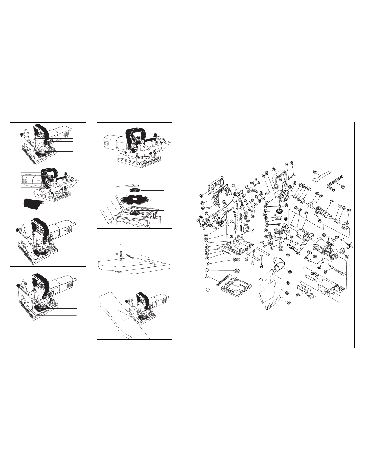
Fig.A
Fig.B
Fig.C
Fig.D
Fig.E
Fig.F
Fig.G
10 - 15 cm
19
18
21
20
17
16
20
9
11
10
4
8
7
15
A
20
9
2
11
10
13
14
12
3
7
15
1
6
8
4
2 Ferm
Ferm 43
EXPLODED VIEW
Page 3
42 Ferm
Fig.H
Fig.I
Fig.J
7
15
A
|
l
l
l
l
|
l
l
l
l
|
l
l
l
l
|
l
l
l
l
|
l
l
l
l
|
l
l
l
l
|
l
l
l
l
|
l
l
l
l
|
4
5
|
l
l
l
l
|
l
l
l
l
|
l
l
l
l
|
l
l
l
l
|
l
l
l
l
|
l
l
l
l
|
l
l
l
l
|
l
l
l
l
|
Ferm 3
SPARE PARTS LIST FBJ-710
REF NR DESCRIPTION FERM NR
407650 UPPER FLANGE 003
407651 LOWER FLANGE 004
407652 STOPPED PIN + NUT 005 + 006
407653 LOCKING KNOB COMPLETE 015 - 019
407655 ADJUSTING KNOB 028
407658 SPINDLE GEAR 054
407659 HANDLE 059
407660 PINION GEAR 066
406059 ROTOR 071
406060 STATOR 077
406061 CARBON BRUSH SET 079
406062 CARBON BRUSH HOLDER 080
406063 SWITCH 082
406064 SWITCH ACTUATOR 086
406065 PULL-ROD FOR SWITCH 090
407661 DUST BAG COMPLETE 096 - 099
407662 WRENCH 100
Page 4
BISCUIT JOINTER
THE NUMBERS IN THE FOLLOWING TEXT
CORRESPOND WITH THE PICTURES AT PAGE 2
& 3
TECHNICAL SPECIFICATIONS
PACKAGE CONTENTS
The package contains:
1 Biscuit Jointer
1 Saw blade
1 Wrench
1 Adjustment plate
1 Allen wrench
1 Dust collection bag
1 Instruction manual
1 Safety instructions
1 Guarantee card
Check the machine, loose parts and accessories for
transport damage.
PRODUCT INFORMATION
Fig.A
The FBJ-710 Biscuit Jointer is suitable for cutting grooves
for biscuit dowel joints in solid wood, plywood,
chipboard, fibre board, plexiglass and artificial marble.
1. On/off switch
2. Auxiliary handle
3. Spindle lock
4. Angle stop
6. Scale for the fence angle
7. Cutting depth adjustment knob
8. Clamping lever for angle adjustment
9. Clamping lever for height adjustment
10. Knob for height adjustment
11. Scale for the height adjustment
12. Base plate
13. Dust bag connection
14. Dust bag
15. Motor base
SAFETY INSTRUCTIONS
The following symbols are used throughout this manual:
Denotes risk of personal injury, loss of life or
damage to the tool in case of non-observance of
the instructions in this manual.
Denotes risk of electric shock.
Carefully read this manual before using the machine.
Make sure that you know how the machine functions and
how to operate it. Maintain the machine in accordance
with the instructions to make sure it functions properly.
Keep this manual and the enclosed documentation with
the machine.
ELECTRIC SAFETY
Always check that the power supply corresponds to
the voltage on the rating plate.
Your machine is double insulated in accordance
with EN 50144; therefore no earth wire is
required.
Replacing cables or plugs
Immediately throw away old cables or plugs when they
have been replaced by new ones. It is dangerous to insert
the plug of a loose cable in the wall socket.
Using extension cables
Only use an approved extension cable suitable for the
power input of the machine. The minimum cable size is
1.5 mm2. When using a cable reel always unwind the reel
completely.
SPECIAL SAFETY PRECAUTIONS
• Sawdust and splinters must not be removed while
the machine is running.
• Do not use cutting discs or circular saw blades in the
machine.
• Protect saw blades against shocks and impacts.
• Only use properly sharpened blades, otherwise
increased cutting forces will shatter the work piece.
• Before use, inspect the saw blade for any damage. Do
not use saw blades which are cracked, ripped or
otherwise damaged.
• Make sure that the work piece is sufficiently
supported or clamped. Keep your hands away from
the surface to be cut.
• Use the machine only with the auxiliary handle
• When saw blades have to be mounted on the thread
of the spindle, make sure that the spindle has
sufficient thread.
• Make sure that the saw blade has been mounted and
fastened properly. Do not use reducing rings or
adapters to make the saw blade fit properly.
• Apply the machine to the work piece only when the
machine is switched on.
• When working with the machine always hold the
machine firmly with both hands and provide for a
secure stance.
• Persons under 16 years of age are not permitted to
operate this machine.
Voltage | 230 V~
Frequency | 50 Hz
Power input | 710 W
No-load speed | 11000/min
Disc diameter | 100 mm
Blade bore diameter | 20+22 mm
Max. cutting depth | 18 mm
Fence adjustment | 0 - 90°
Spindle dimension | M10
Weight | 3.0 kg
Lpa (sound pressure) | 89.6 dB(A)
Lwa (sound power level) | 102.6 dB(A)
Vibration value | 1.9 m/s
2
4 Ferm Ferm 41
Page 5
• Always wear safety goggles and hearing protection. If
desired or required also use another protection for
example an apron or helmet.
• Always disconnect the plug from the socket before
carry out any work on the machine. Only plug-in
when the machine is switched off.
• Keep mains lead clear from working range of the
machine. Always lead the cable away behind you.
• Do not stop the blade by hand after switching off.
• The base plate must not be clamped down while the
blade is extended. Lowering and raising the blade
must be a smooth operation.
ADJUSTING THE MACHINE
ADJUSTING THE CUTTING DEPTH
Fig.B
• Move the motor base (15) as far as possible
backwards.
• Set the cutting depth by turning the cutting depth
adjustment knob (7).
• Move the motor base forwards and check if the pin
(A) will fall in the notch of the adjustment knob.
The following table shows the relationship of the
markings on the adjustment knob to cutting depth,
thickness of material and associated biscuit dowel:
Marking Thickness Biscuit Cutting
of material Dowel depth in mm
0 8-12 mm No. 0 8.0
10 12-15 mm No. 10 10.0
20 > 15 mm No. 20 12.3
S-Simplex 13.0
D-Duplex 14.7
Max. - - 18.0
ADJUSTING THE CUTTING ANGLE
Fig. C
• The cutting angle can be set by unlocking the
clamping lever (8) and put the angle stop (4) in the
required angle.
• Should the clamping lever be in the way when
working with the tool, then pull the clamping lever
out and fasten it in a different position without
changing the cutting angle.
ADJUSTING THE HEIGHT
Fig. D
• The correct height can be set by unlocking the
clamping lever (9) and turning the knob for the height
adjustment (10) to the desired height with aid of the
scale (11).
• The height must corresponds to half of the material
thickness of the working piece, the groove for the
biscuit dowel must always be in the middle of the
working piece.
• Should the clamping lever be in the way when
working with the tool, then pull the clamping lever
out and fasten it in a different position without
changing the height.
MOUNTING ACCESSORIES
Disconnect the plug from the main socket
MOUNTING SAW BLADE
Fig. E
• Loosen the allen screw (16) with the supplied allen
wrench and open the top of the base plate
• Press the spindle lock and turn the spindle (17) until it
engages in the lock. Keep the spindle lock pressed
during this procedure.
• Remove the flange nut (18) from the spindle using the
wrench (19).
• Position the saw blade (20) on the flange (21).
• Place the flange nut (18) on the spindle (17) and
tighten it with the wrench.
• The flange nut has two sides. One for sawblades with
bore 20 mm and the otherside for sawblades with
bore 22 mm.
Take care that the flange nut will be placed with the
correct side on the spindle.
• Release the spindle lock and check that the spindle is
unlocked by rotating it.
• Close the top of the base plate and fasten the allen
screw (16) with the supplied allen wrench.
Make sure that the top of the base plate is securely
closed before operating the machine.
MOUNTING DUST BAG
Fig. A
For dust extraction the dust bag (14) can be used.
Insert the dust bag (14) into the vacuuming connection
(13). Empty the dust bag regularly so that the vacuuming
performance remains intact.
OPERATION
SWITCHING ON AND OFF
Never use the spindle lock while the machine is
working.
• To switch the machine on slide the on/off switch
forwards.
• To switch the machine off, depress the on/off switch,
the switch will automatically move to the ‘off’
position.
Never use the spindle lock to stop the motor.
MARKING THE WORKPIECES
Fig. F
Before starting with the Biscuit Jointer the workpieces
must be marked as following:
• Place the two workpieces, which must be connected,
on top of each other.
• Fasten the workpieces and mark the center of the
groove.
• The space between two grooves should be 10-15
cm, this doesn’t concerns for smaller workpieces.
Smaller workpieces don’t have to be marked.
Ferm 540 Ferm
Page 6

Ferm 39
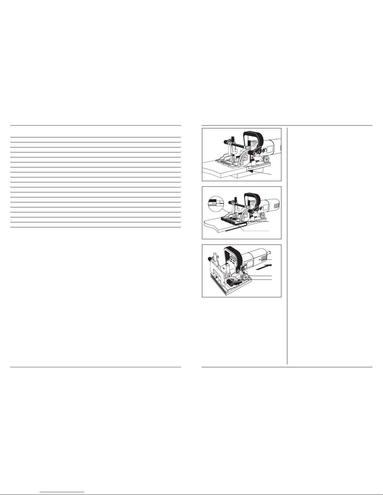
POSITIONING OF THE MACHINE
Based on the size of the workpieces the machine can be
positioned in several ways.
LARGE WORKPIECES
Fig. G
• Place the machine near the workpiece.
• The middle of the base plate (this point is marked on
the base plate) must facing the centre of the groove in
the workpiece (see marking the workpiece).
SMALL WORKPIECES
Fig. H
• Place the machine near the workpiece.
• The side of the machine must be facing the side of the
workpiece.
WORKPIECESTHINNER THAN 16 MM
Fig. I
• Place the machine near the workpiece.
• Place the adjustment plate (5) on the angle stop (4).
• Take care for setting the height, the groove for the
biscuit dowel must be in the middle of the workpiece.
For workpieces thinner than 16mm it is not possible to
make the groove for the biscuit dowel in the middle of
the workpiece without the aid of the adjustment plate.
SAWING GROOVES
• Move the motor base backward.
• Place the machine near the workpiece.
• Position the machine (see positioning of the
machine)
• Hold the machine with both hands and switch the
machine on.
• Push the motor base carefully forward as far as
possible.
• Move the motor base backward and switch the
machine off.
JOINING THE WORKPIECES
When the grooves in both workpieces have been made
the workpieces can be joined together:
• Put glue in both grooves.
• Place the biscuit dowel in the groove of one
workpiece.
• Place the other workpiece on the biscuit dowel.
• Fasten the workpieces and wait till the glue is dry.
CHECKING THE CUTTING DEPTH
Fig. J
Always check the cutting depth after mounting a
saw blade:
• Disconnect the plug from the socket.
• Move the motor base (15) as far as possible backwards.
• Set the cutting depth in the maximum position by
turning the depth adjustment knob (7).
• Move the motor base forwards till the pin (A) will fall
in the notch of the adjustment knob (7).
Turn the saw blade till one tooth of the saw blade is in
the front position.
• Measure the distance from the side of the base plate
to the tooth of the saw blade
• Check if the distance is 18 mm. the maximum
position is 18 mm.
SETTING THE CUTTING DEPTH
When the cutting depth is not correct, it can be adjusted
as following:
• Move the motor base (15) as far as possible
backwards.
• Loosen the pin (A).
• Set the cutting depth by turning the screw, the screw
is positioned at the back of the pin (A).
• Repeat the procedure till the cutting depth is correct
• Fasten the pin (A).
MAINTENANCE
Make sure that the machine is not live and
unplugged when carrying out maintenance work
on the motor.
The Ferm machines have been designed to operate over
along period of time with a minimum of maintenance.
Continuous satisfactory operation depends upon
proper machine care and regular cleaning.
Cleaning
Regularly clean the machine housing with a soft cloth,
preferably after each use. Keep the ventilation slots free
from dust and dirt. If the dirt does not come off use a soft
cloth moistened with soapy water. Never use Solvents
such as petrol, alcohol, ammonia water, etc. These
solvents may damage the plastic parts. Keep the moving
parts of the machine clean, like the guiding pillars, the
mechanism of the heigt adjustment and angle
adjustment, to ensure good working.
Lubrication
The machine requires no additional lubrication.
Faults
Should a fault occur, e.g. after wear of a part, please
contact your local Ferm dealer.
In the back of this manual you find an exploded view
showing the parts that can be ordered.
ENVIRONMENT
In order to prevent the machine from damage during
transport, it is delivered in a sturdy packaging. Most of
the packaging materials can be recycled. Take these
materials to the appropriate recycling locations.
6 Ferm
Page 7
GUARANTEE
The guarantee conditions can be found on the separately
enclosed guarantee card.
We declare under our sole responsibility that this
product is in conformity with the following standards or
standardized documents
EN60475-1, EN60475-2-5, EN55014-1,
EN-55014-2, EN61000-3-2, EN61000-3-3
in accordance with the regulations.
98/37EEC
73/23EEC
89/336EEC
from 01-03-2004
ZWOLLE NL
W. Kamphof
Quality department
BISCUIT JOINTER
DIE NUMMERN IM NACHFOLGENDEN TEXT
KORRESPONDIEREN MIT DEN ABBILDUNGEN
AUF SEITE 2 & 3
TECHNICAL DATEN
INHALT DER VERPACKUNG
Die Verpackung enthält:
1 Schattenfugenfräse
1 Scheibenfräser
1 Schraubenschlüssel
1 Einstellplatte
1 Innensechskantschlüssel
1 Staubsack
1 Betriebsanleitung
1 Sicherheitsheft
1 Garantiekarte
Überprüfen Sie die Maschine, lose Teile und Zubehör auf
Transportschäden.
PRODUKT INFORMATION
Abb.A
Die Schattenfugenfräse FBJ-710 ist bestimmt zum Fräsen
von Nuten für Schattenfugenverbindungen in
Massivholz, Sperrholz, Spannplatten, Faserplatten und
Kunstmarmor.
1. Ein-Aus-Schalter
2. Handgriff
3. Spindelarretierung
4. Parallelanschlag
6 Skala für den Parallelanschlag
7. Knopf zur Einstellung der Schnitttiefe
8. Klemmhebel für die Winkeleinstellung
9. Klemmhebel für die Höheneinstellung
10. Knopf zur Höheneinstellung
11. Skala zur Höheneinstellung
12. Grundplatte
13. Spanauswurf
14. Staubsack
15. Antriebsmotor
Netzspannung | 230 V~
Netzfrequenz | 50 Hz
Nennaufnahmeleistung | 710 W
Nullastdrehzahl | 11000 U/min
Scheibenfräserdurchmesser | 100 mm
Scheibenfräserbohrung | 20 mm/22 mm
Maximale Schnitttiefe | 18 mm
Anschlagwinkel | 0 – 90°
Spindelgewinde | M10
Gewicht | 3,0 kg
Schalldruck (Lpa) | 89.6 dB(A)
Schallleistungspegel (Lwa) | 102.6 dB(A)
Schwingungswert (aw) | 1.9 m/s
2
CE
ı
DECLARATION OF CONFORMITY
(UK)
Ferm 7
INDSTILLING AF FRÆSEDYBDE
Når fræsedybden ikke er korrekt, kan den justeres på
følgende måde.
• Flyt motorhuset (15) så langt tilbage som muligt.
• Løsn stiften (A).
• Indstil fræsedybden ved at dreje på skruen, som er
bagved stiften (A).
• Gentag dette, indtil fræsedybden er korrekt.
• Sæt stiften (A) fast.
VEDLIGEHOLDELSE
Sørg for, at maskinen ikke er strømførende, og at
stikket er trukket ud, når motoren vedligeholdes.
Maskinerne fra Ferm er udviklet til at fungere længe uden
problemer med et minimum af vedligeholdelse. Ved at
rengøre maskinen regelmæssigt og behandle den
korrekt, bidrager De til en længere levetid for maskinen.
Rengøring
Rengør regelmæssigt maskinkappen med en blød klud,
helst efter hvert brug. Sørg for at ventilationshullerne er
fri for støv og snavs.
Brug en blød klud, der er vædet i sæbevand til at fjerne
hårdnakket snavs. Brug ingen opløsningsmidler, så som
benzin, alkohol, ammoniak, osv. Den slags stoffer
beskadiger kunststofdelene.
Smøring
Maskinen behøver ingen ekstra smøring.
Fejl
Kontakt Deres Ferm-forhandler, hvis der opstår fejl som
følge af slitage af en del. Bagerst i denne brugsanvisning
finder De en reservedelstegning med de reservedele,
der kan bestilles.
MILJØ
For at undgå transportbeskadigelse leveres maskinen i
en solid emballage. Emballagen er så vidt muligt lavet af
genbrugsmateriale. Genbrug derfor emballagen.
Når de udskifter Deres maskinen bør De tage den gamle
maskine med til Deres lokale Ferm-forhandler. Der vil
maskinen blive bearbejdet på miljøvenlig vis.
GARANTI
Læs det separat vedlagte garantikort for
garantibetingelserne.
Vi erklærer herved, udelukkende på eget ansvar, at dette
produkt opfylder følgende standarder eller
standardiserede dokumenter
EN60475-1, EN60475-2-5, EN55014-1,
EN-55014-2, EN61000-3-2, EN61000-3-3
i henhold til følgende direktiver:
98/37EEC
73/23EEC
89/336EEC
01-03-2004
ZWOLLE NL
W. Kamphof
Quality department
CE
ı
KONFORMITETSERKLÆRING
(DK)
38 Ferm
Page 8

MONTERING AF TILBEHØR
Tag stikket ud af stikkontakten.
MONTERING AF SAVKLINGE
Fig. E
• Løsn unbrakoskruen (16) ved hjælp af den
medfølgende unbrakonøgle, og løft låget til
bundpladen.
• Tryk på spindellåsen, og drej spindlen (17), til den går
ind i låsen. Hold spindellåsen trykket ned under
denne procedure.
• Afmonter flangemøtrikken (18) på spindlen ved
hjælp af skruenøglen (19).
• Anbring savklingen (20) på flangen (21).
• Anbring flangemøtrikken (18) på spindlen (17), og
stram den med skruenøglen.
• Flangemøtrikken har to sider. En side til savklinger
med en huldiameter på 20 mm og den anden side til
savklinger med en huldiameter på 22 mm.
Kontroller, at flangemøtrikken er anbragt med den
korrekte side mod spindlen.
• Udløs spindellåsen og kontroller, at spindlen ikke er
låst ved at dreje den.
• Luk låget på bundpladen, og fastgør unbrakoskruen
(16) med unbrakonøglen.
Kontroller, at toppen på bundpladen er lukket, før
maskinen tændes.
MONTERING AF STØVPOSE
Fig. A
Støvposen (14) kan bruges til støvudsugning.
Tilslut støvposen (14) til støvudsugningsforbindelsen
(13). Tøm regelmæssigt støvposen.
BRUG AF MASKINEN
TÆND OG SLUK
Brug kun spindellåsen, når maskinen er tændt.
• Skub tænd-sluk-knappen frem for at tænde
maskinen.
• Tryk på tænd-sluk-knappen igen for at slukke
maskinen, og knappen vil automatisk stille sig på
"sluk".
Brug aldrig spindellåsen til at slukke for motoren.
MARKERING AF ARBEJDSEMNERNE
Fig. F
Før skyggefugefræseren tændes, skal arbejdsemnerne
markeres på følgende måde:
• Anbring de to arbejdsemner, som skal forbindes,
oven på hinanden.
• Fastgør arbejdsemnerne, og marker midten af
fugespalten.
• Afstanden mellem to fugespalter bør være 10-15 cm.
Dette gælder dog ikke for mindre arbejdsemner,
som ikke skal markeres.
ANBRINGELSE AF MASKINEN
Afhængig af arbejdsemnernes størrelse, kan maskinen
anbringes på flere måder.
STØRRE ARBEJDSEMNER
Fig. G
• Anbring maskinen tæt på arbejdsemnet.
• Midten af bundpladen (er markeret på bundpladen)
skal vende mod midten af arbejdsemnets fugespalte
(se markering af arbejdsemnerne).
MINDRE ARBEJDSEMNER
Fig. H
• Anbring maskinen tæt på arbejdsemnet.
• Maskinens side skal vende mod arbejdsemnets side.
ARBEJDSEMNER SMALLERE END 16 MM
Fig. I
• Anbring maskinen tæt på arbejdsemnet.
• Anbring justeringspladen (5) på vinkelstoppet (4).
• Sørg for, at skyggefugen til dyvlen er i midten af
arbejdsemnet.
Hvis arbejdsemnerne er smallere end 16 mm, kan
skyggefugen til dyvlen kun laves i midten af arbejdsemnet
ved brug af justeringspladen.
SAVNING AF FUGESPALTER
• Flyt motorhuset tilbage.
• Anbring maskinen tæt på arbejdsemnet.
• Anbring maskinen (se anbringelse af maskinen)
• Hold maskinen med begge hænder, og tænd den.
• Skub forsigtigt motorhuset så langt frem som muligt.
• Træk motorhuset tilbage, og sluk for maskinen.
SAMLING AF ARBEJDSEMNER
Når fugespalterne i begge arbejdsemner er lavet, kan
arbejdsemnerne samles:
• Put lim i begge fugespalter.
• Anbring dyvlen i et af arbejdsemnernes fugespalter.
• Anbring det andet arbejdsemne på dyvlen.
• Fastgør arbejdsemnerne, og vent til limen er tør.
KONTROL AF FRÆSEDYBDE
Fig. J
Kontroller altid fræsedybden, efter savklingen er
monteret:
• Tag stikket ud af stikkontakten.
• Træk motorhuset (15) så langt tilbage som muligt.
• Indstil fræsedybden på den maksimale position ved at
dreje knappen til justering af fræsedybden (7).
• Flyt motorhuset frem, indtil stiften (A) glider ind i
hakket på justeringsknappen.
Drej savklingen, indtil en af savklingens tænder er i
forreste position.
• Mål afstanden mellem bundpladens side og
savklingens tand.
• Kontroller, at afstanden er 18 mm. Den maksimale
position er 18 mm.
Ferm 37
SICHERHEITSVORSCHRIFTEN
In dieser Betriebsanleitung erscheinen folgende
Piktogramme:
Verweist auf Verletzungsgefahr, Gefahr für Leben
und mögliche Beschädigung der Maschine, falls die
Anweisungen in dieser Betriebsanleitung nicht befolgt werden.
Deutet das Vorhandensein elektrischer Spannung
an.
Lesen Sie diese Betriebsanleitung aufmerksam, bevor Sie
die Maschine in Betrieb nehmen. Machen Sie sich
vertraut mit der Funktionsweise und der Bedienung.
Warten Sie die Maschine entsprechend den
Anweisungen, damit sie immer einwandfrei funktioniert.
Die Betriebsanleitung und die dazugehörende
Dokumentation müssen in der Nähe der Maschine
aufbewahrt werden.
ELEKTRISCHE SICHERHEIT
Überprüfen Sie immer, ob Ihre Netzspannung der
des Typenschilds entspricht.
Die Maschine ist nach EN 50144 doppelisoliert;
daher ist Erdung nicht erforderlich.
Austauschen von Kabeln oder Steckern
Entsorgen Sie alte Kabel oder Stecker, unmittelbar
nachdem Sie durch neue ersetzt sind. Das Anschließen
eines Steckers eines losen Kabels an eine Steckdose ist
gefährlich.
Verwendung von Verlängerungskabeln
Benutzen Sie nur ein genehmigtes Verlängerungskabel,
das der Maschinenleistung entspricht. Die Ader müssen
einen Mindestquerschnitt von 1,5 mm2haben. Befindet
das Kabel sich auf einem Haspel. muß es völlig abgerollt
werden.
SPEZIELE SICHERHEITSVORSCHRIFTEN
• Sägestaub und Späne brauchen beim Betrieb der
Maschine nicht entfernt zu werden.
• Benutzen Sie mit der Maschine keine Trennscheiben
oder Kreissägeblätter.
• Schützen Sie Scheibenfräser gegen Stoß und Schlag.
• Verwenden Sie nur unbeschädigte, scharfe Scheiben,
da anderenfalls das Werkstück splittern könnte.
• Inspizieren Sie vor dem Beginn der Arbeit den
Scheibenfräser auf Beschädigungen. Verwenden Sie
keine verbogenen, gerissenen oder sonst wie
beschädigten Scheiben.
• Achten Sie darauf, dass das Werkstück sorgfältig
aufliegt und eingespannt ist. Halten Sie Ihre Hände
von der Bearbeitungsstelle fern.
• Halten Sie die Fräse nur am Handgriff.
• Vergewissern Sie sich, dass beim Anbringen eines
Scheibenfräsers auf der Antriebsspindel ausreichend Gewindegänge vorhanden sind.
• Achten Sie darauf, dass der Scheibenfräser sorgfältig
fest sitzt. Verwenden Sie beim Anbringen eines
Scheibenfräsers keine Unterlegscheiben oder
sonstigen Hilfsmittel, um den Sitz zu verbessern.
• Bewegen Sie den Scheibenfräser nur bei
eingeschalteter Maschine auf das Werkstück zu.
• Halten und führen Sie die Maschine bei der Arbeit
immer mit zwei Händen und sorgen Sie selbst für
einen festen Stand.
• Personen unter 16 Jahren dürfen die Maschine nicht
bedienen.
• Tragen Sie bei der Arbeit eine Sicherheitsbrille und
einen Gehörschutz. Falls erforderlich tragen Sie auch
andere Schutzmittel, beispielsweise eine Schürze
und einen Schutzhelm.
• Vor allen Arbeiten am Gerät müssen Sie den
Netzstecker ziehen. Stecken Sie den Netzstecker
nur bei ausgeschalteter Maschine ein.
• Halten Sie das Anschlusskabel fern von der
Arbeitsstelle; führen Sie es immer hinter Ihnen längs.
• Bremsen Sie den Scheibenfräser nach dem
Ausschalten nicht mit der Hand ab.
• Bei offen liegendem Scheibenfräser darf die
Grundplatte nicht festgeklemmt sein. Das Auf- und
Abbewegen der Scheibe muss leicht gehen.
EINSTELLUNG DER MASCHINE
EINSTELLUNG DER SCHNITTIEFE
Abb. B
• Ziehen Sie den Antriebsmotor (15) so weit wie
möglich zurück.
• Stellen Sie die gewünschte Schnitttiefe mit dem
Knopf zur Einstellung der Schnitttiefe (7) ein.
• Schieben Sie den Motor nach vorne und prüfen Sie,
ob der Zapfen (A) in die Kerbe des Einstell-knopfes
einrastet.
Die folgende Tabelle gibt die Beziehung der
Markierungen a Einstellknopf zur Schnitttiefe, zur
Material-stärke und des betreffenden Schattendübels an:
Markierung Material- Schatten- Schnitttiefe
Stärke dübel in mm
0 8-12 mm No. 0 8.0
10 12-15 mm No. 10 10.0
20 > 15 mm No. 20 12.3
S-Simplex 13.0
D-Duplex 14.7
Max. - - 18.0
EINSTELLUNG DES SCHNITTWINKELS
Abb. C
• Zum Einstellen des Schnittwinkels lösen Sie den
Arretierhebel (8) und stellen den Parallelanschlag (4)
in die gewünschte Lage.
• Sollte der Arretierhebel beim Fräsen im Wege sein,
ziehen Sie ihn heraus und setzen ihn in einer anderen
Stellung ein, ohne den Schnittwinkel zu ändern.
EINSTELLUNG DER HÖHE
Abb. D
• Zum Einstellen der richtigen Höhe lösen Sie den
Arretierhebel (9) und drehen den Höheneinstellknopf (10) mithilfe der Skala (11) in die gewünschte
Höhe.
8 Ferm
Page 9

• Die Höhe muss die halbe Randflächenhöhe des
Werkstücks betragen. Die Nut für den Schatten-dübel
muss immer in der Mitte des Werkstückrands liegen.
• Sollte der Arretierhebel beim Fräsen im Wege sein,
ziehen Sie ihn heraus und setzen ihn in einer anderen
Stellung fest, ohne die Höhe zu ändern.
MONTAGEZUBEHÖR
Lösen Sie den Stift von der Grundplatte
EINSETZEN DES SCHEIBENFRÄSERS (Abb. E)
• Lösen Sie die Innensechskantschraube (16) mit dem
mitgelieferten Innensechskantschlüssel und öffnen
Sie die Abdeckhaube der Grundplatte.
• Drücken Sie die Spindelarretierung und drehen Sie
die Antriebsspindel (17), bis sie einrastet.
Halten Sie die Spindelarretierung während der
ganzen Zeit gedrückt.
• Entfernen Sie mit dem Schraubenschlüssel (19) den
Spannflansch (18) von der Antriebsspindel.
• Legen Sie den Scheibenfräser (20) auf die
Distanzbuchse (21).
• Bringen Sie den Spannflansch (18) wieder an der
Antriebsspindel (17) an und drehen Sie mit dem
Schraubenschlüssel fest.
• Der Spannflansch hat zwei Seiten, eine für
Scheibenfräser mit einer Mittelbohrung von 20 mm
und eine für Scheibenfräser mit 22 mm
Mittelbohrung.
Achten Sie darauf, dass Sie den Spannflansch mit der
richtigen Seite auf der Antriebsspindel an-bringen.
• Lassen Sie die Spindelarretierung los und prüfen Sie
durch Drehen der Antriebsspindel, dass sie nicht
mehr blockiert ist.
• Schließen Sie die Grundplattenabdeckhaube wieder
und drehen Sie die Innensechskantschraube mit dem
Innensechskantschlüssel wieder fest.
Vergewissern Sie sich vor Beginn der Arbeit, dass
die Grundplatte ordnungsgemäß geschlossen ist.
ANBRINGEN DES STAUBSACKS
Abb. A
Zum Auffangen der Frässpäne kann der Staubsack
verwendet werden.
Setzen Sie den Staubsack (14) in den Spanauswurf (13)
ein. Entleeren Sie den Staubbeutel regelmäßig, um eine
einwandfreie Funktion zu gewährleisten.
ARBEITEN MIT DER
SCHATTENFUGENFRÄSE
EIN- UND AUSSCHALTEN.
Benutzen Sie die Spindelarretierung niemals bei
laufendem Motor
• Zum Einschalten des Motors schieben Sie den EinAus-Schalter nach vorne.
• Zum Ausschalten drücken Sie den Ein-Aus-Schalter,
wodurch er von selbst in die Ausstellung
zurückspringt.
Benutzen Sie die Spindelarretierung nicht zum
Anhalten des Motors.
ANREIßEN DES WERKSTÜCKS
Abb. F
Bevor Sie mit der Schattenfugenfräse zu arbeiten
beginnen, muss das Werkstück folgendermaßen angerissen werden:
• Legen Sie die beiden Stücke, die verbunden werden
sollen, flach gegeneinander.
• Spannen Sie die beiden Stücke ein und zeichnen Sie
die Mitte der Nut an.
• Der Abstand zwischen zwei Nuten muss 10-15 cm
betragen. Dies gilt nicht für kleinere Werkstücke,
diese brauchen nicht angerissen zu werden.
ANSETZEN DER MASCHINE
Je nach der Größe der Werkstücke kann die Maschine
auf verschiedene Arten angesetzt werden.
GROßE WERKSTÜCKE
Abb. G
• Stellen Sie die Maschine nahe an das Werkstück.
• Die Mittenmarkierung an der Grundplatte muss der
angezeichneten Mitte der neuen Nut gegenüberliegen.
KLEINE WERKSTÜCKE
Abb. H
• Stellen Sie die Maschine nahe an das Werk stück.
• Die Arbeitsseite der Maschine muss am Werkstück
anliegen.
WERKSTÜCKE DÜNNER ALS 16 MM
Abb. I
• Stellen Sie die Maschine nahe an das Werkstück.
• Legen Sie die Einstellplatte (5) auf den
Parallelanschlag (4).
• Stellen Sie die Höhe sorgfältig ein; die Nut für den
Schattendübel muss genau in der Randmitte des
Werkstücks liegen.
Für weniger als 16 mm dicke Werkstücke kann die Nut
für den Schattendübel nicht ohne die Hilfe der
Einstellplatte genau in der Randmitte des Werkstücks
hergestellt werden.
FRÄSEN EINER NUT
• Ziehen Sie den Motor zurück.
• Stellen Sie die Maschine nahe an das Werkstück.
• Setzen Sie die Maschine an (siehe oben: 'Ansetzen
der Maschine').
• Halten Sie die Maschine mit beiden Händen fest und
schalten Sie sie ein.
• Drücken Sie die Grundplatte langsam so weit, wie es
geht, nach vorne.
• Ziehen Sie die Grundplatte zurück und schalten Sie
die Maschine aus (Schalter drücken).
VERBINDEN DER WERKSTÜCKE
Nachdem in beiden Werkstücken eine Nut angebracht
worden ist, können sie miteinander verbunden werden.
Ferm 9
SIKKERHEDSFORSKRIFTER
I denne brugsanvisning anvendes de følgende
piktogrammer:
Angiver risiko for legemensbeskadigelse, livsfare
eller maskinskade, hvis instruktionerne i denne
brugsanvisning tilsidesættes.
Angiver elektrisk spænding.
Læs denne brugsanvisning godt igennem før maskinen
tages i brug. Sørg for at De kender maskinens funktion og
betjening. Vedligehold maskinen i følge instruktionerne,
for at maskinen altid kan fungere optimalt. Bevar denne
brugsanvisning og den vedlagte dokumentation til
maskinen.
ELEKTRISK SIKKERHED
Kontroller altid om netspændingen svarer til
værdien på typeskiltet.
Maskinen er dobbeltisoleret i henhold til EN
50144; det er derfor ikke nødvendigt med en
jordledning.
Ved udskiftning af ledninger og stik
Kasser gamle ledninger og stik, så snart de er skiftet ud
med nye. Det er farligt at sætte et stik fra en løs ledning i
en stikkontakt.
Ved brug af forlængerledninger
Brug udelukkende godkendte forlængerledninger, der
er beregnede til maskinens effekt. Lederne skal have et
gennemsnit på mindst 1,5 mm2. Hvis forlængerledningen
sidder på en tromle, rulles ledningen helt af.
SÆRLIGE
SIKKERHEDSFORANSTALTNINGER
• Savsmuld og flis må ikke fjernes, mens maskinen er i
drift.
• Brug ikke skæreskiver eller runde savklinger i
maskinen.
• Beskyt savklingerne mod stød.
• Brug kun klinger, som er korrekt slebet, ellers
ødelægges arbejdsemnet.
• Kontroller savklingen for skader før brug. Brug ikke
revnede eller på anden måde ødelagte savklinger.
• Kontroller, at arbejdsemnet er tilstrækkeligt
understøttet eller fastspændt. Hold hænderne væk
fra den overflade, der skal skæres i.
• Maskinen må kun bruges sammen med
hjælpehåndtaget.
• Ved montering af savklinger på spindlens gevind
kontrolleres det, at gevindet passer i længden.
• Kontroller, at savklingen er korrekt monteret og
fastspændt. Der må ikke anvendes reduktionsringe
eller tilpasningsstykker for at få klingen til at passe
korrekt.
• Anbring først maskinen på arbejdsemnet, når
maskinen er tændt.
• Hold altid maskinen med begge hænder, og sørg for
sikker fodstilling under arbejdet.
• Personer under 16 år må ikke betjene maskinen.
• Brug altid beskyttelsesbriller og høreværn. Der kan
også benyttes andet beskyttelsesudstyr, f.eks.
beskyttelsesforklæde eller hjelm.
• Tag altid stikket ud af kontakten, før der udføres
arbejde på maskinen. Sæt altid stikket i, når maskinen
er slukket.
• Sørg for, at hovedledningen holdes væk fra
maskinens arbejdsområde. Hold altid kablet bag dig.
• Stop ikke savklingen med hånden, efter at maskinen
er slukket.
• Bundpladen må ikke fastspændes, mens klingen
stikker frem. Klingen skal hæves og sænkes jævnt.
JUSTERING AF MASKINE
JUSTERING AF FRÆSEDYBDE
Fig. B
• Flyt motorhuset (15) så langt tilbage som muligt.
• Indstil fræsedybden ved at dreje knappen til justering
af fræsedybden (7).
• Flyt motorhuset frem og kontroller, at stiften (A)
glider ind i hakket på justeringsknappen.
Nedenstående tabel angiver forholdet mellem
markeringerne på justeringsknappen og fræsedybde,
materialetykkelse og den tilknyttede dyvel:
Markering Materiale- Dyvel Fræse-
tykkelse dybde i mm
0 8-12 mm No. 0 8.0
10 12-15 mm No. 10 10.0
20 > 15 mm No. 20 12.3
S- Simplex 13.0
D- Duplex 14.7
Max. - - 18.0
JUSTERING AF FRÆSEVINKEL
Fig. C
• Fræsevinklen kan indstilles ved at låse spændearmen
op (8) og indstille vinkelstoppet (4) i den krævede
vinkel.
• Hvis spændearmen er i vejen, når der arbejdes med
værktøjet, trækkes spændearmen ud og fastgøres i
en anden position uden at ændre fræsevinklen.
HØJDEJUSTERING
Fig. D
• Den korrekte højde indstilles ved at låse
spændearmen op (9) og dreje knappen til justering af
højde (10) til den ønskede højde ved hjælp af skalaen
(11).
• Højden skal svare til halvdelen af arbejdsemnets
tykkelse, og skyggefugen til dyvlen skal altid være i
midten af arbejdsemnet.
• Hvis spændearmen er i vejen, når der arbejdes med
værktøjet, trækkes spændearmen ud og fastgøres i
en anden position uden at ændre højden.
36 Ferm
Page 10

GARANTI
Garantibetingelsene er å finne på det vedlagte
garantikortet.
Vi erklærer på eget ansvar at dette produktet er i
samsvar med følgende standarder eller standardiserte
dokumenter.
EN60475-1, EN60475-2-5, EN55014-1,
EN-55014-2, EN61000-3-2, EN61000-3-3
i samsvar med bestemmelsene.
98/37EEC
73/23EEC
89/336EEC
fra 01-03-2004
ZWOLLE NL
W. Kamphof
Kvalitetsavdelingen
VINKELSLIBER
TALLENE I DEN FØLGENDE TEKST
KORRESPONDERER MED AFBILDNINGERNE PÅ
SIDE 2 & 3.
TEKNISKE SPECIFIKATIONER
EMBALLAGENS INDHOLD
Kassen indeholder:
1 Skyggefugefræser
1 Savklinge
1 Skruenøgle
1 Justeringsplade
1 Unbrakonøgle
1 Støvpose
1 Brugsanvisning
1 Sikkerhedsfolder
1 Garantikort
Kontroller maskinen, løsdele og tilbehør for
transportskade.
PRODUKTINFORMATION
Fig. A
FBJ-710 skyggefugefræser er velegnet til at fræse
skyggefuger til dyvelsamlinger i massivt træ, krydsfiner,
spånplader, fiberplader, plexiglas og kunstigt marmor.
1. Tænd-sluk-knap
2. Hjælpehåndtag
3. Spindellås
4. Vinkelstop
6. Skala til vinkelanslag
7. Knap til justering af fræsedybde
8. Spændearm til vinkeljustering
9. Spændearm til højdejustering
10. Knap til højdejustering
11 Skala til højdejustering
12. Bundplade
13. Tilslutning til støvpose
14. Støvpose
15. Motorhus
Spænding | 230 V~
Frekvens | 50 Hz
Indgangseffekt | 710 W
Tomgangshastighed | 11.000/min.
Skivens diameter | 100 mm
Klingens huldiameter | 20+22 mm
Maksimal fræsedybde | 18 mm
Justering af anslag | 0-90°
Spindelstørrelse | M10
Vægt | 3.0 kg
Lpa (lydtryk) | 89.6 dB(A)
Lwa (lydeffekt) | 102.6 dB(A)
Vibrationsværdi | 1.9 m/s
2
CE
ı
ERKLÆRING AV ANSVARSFORHOLD
(N)
Ferm 35
• Bringen Sie in beiden Nuten Klebstoff an.
• Setzen sie in eine der beiden Nuten einen
Schattendübel ein.
• Schieben Sie das andere Werkstück über den Dübel
• Spannen Sie die Werkstücke ein und warten sie auf
das Aushärten des Klebstoffs.
PRÜFEN DER SCHNITTIEFE
Abb. J
Prüfen Sie nach dem Einsetzen eine Scheibenfräsers
immer die Schnitttiefe:
• Ziehen Sie den Netzstecker.
• Ziehen Sie den Motor (15) so weit wie möglich
zurück.
• Stellen Sie mit dem Tiefeneinstellknopf (7) die
größtmögliche Schnitttiefe ein.
• Bewegen Sie den Motor nach vorne, bis der Stift (A)
in die Nut des Einstellknopfes (7) einrastet.
Drehen Sie die Scheibe, bis ein Zahn der Scheibe
nach vorne gerichtet ist.
• Messen Sie den Abstand von der Zahnspitze bis zur
Grundplatte.
• Prüfen Sie, ob der Abstand 18 mm beträgt, wenn er
18 mm betragen soll.
EINSTELLEN DER SCHNITTIEFE
Wenn die Schnitttiefe neu eingestellt werden soll,
handeln Sie folgendermaßen:
• Ziehen Sie den Motor (15) so weit wie möglich
zurück.
• Lösen Sie den Stift (A).
• Stellen Sie durch Drehen der Schraube in der
Rückseite des Stiftes (A) die Tiefe neu ein.
• Wiederholen Sie die Einstellung, bis die Schnitttiefe
richtig ist.
• Arretieren Sie den Stift (A).
WARTUNG
Bei der Ausführung von Wartungsarbeiten muss
die Maschine außer Betrieb und der Netzstecker
gezogen sein.
Die Maschinen von Ferm sind entworfen, um während
einer langen Zeit problemlos und mit minimaler
Wartung zu funktionieren. Sie Verlängern die
Lebensdauer, indem Sie die Maschine regelmäßig
reinigen und fachgerecht behandeln.
Reinigen
Reinigen Sie das Maschinengehäuse regelmäßig mit
einem weichen Tuch, vorzugsweise nach jedem Einsatz.
Halten Sie die Lüfterschlitze frei von Staub und Schmutz
Entfernen Sie hartnäckigen Schmutz mit einem weichen
Tuch, angefeuchtet mit Seifenwasser. Verwenden Sie
keine Lösungsmittel wie Benzin, Alkohol, Ammonia,
usw. Derartige Stoffe beschädigen die Kunststoffteile.
Schmieren
Die Maschine braucht keine zusätzliche Schmierung.
Störungen
Wenden Sie sich in Störungsfällen, z.B. durch Verschleiß
eines Teils, an Ihren örtlichen Ferm-Vertragshändler.
Am Ende dieser Betriebsanleitung finden Sie eine
Zeichnung der erhältlichen Ersatzteile.
UMWELT
Um Transportschäden zu verhinderen, wird die
Maschine in einer soliden Verpackung geliefert. Die
Verpackung besteht weitgehend aus verwertbarem
Material. Benutzen Sie also die Möglichkeit zum
Recyclen der Verpackung.
Bringen Sie bei Ersatz die alten Maschinen zu Ihren
örtlichen Ferm-Vertagshändler. Er wird sich um eine
umweltfreundliche Verarbeitung ïhrer alten Maschine
bemühen.
GARANTIE
Lesen Sie die Garantiebedingungen auf der separat
beigefügten Garantiekarte.
Wir erklären unsere alleinige Verantwortung, dass
dieses Produkt konform den nachstehenden Standards
oder standardisierten Dokumenten ist.
EN60475-1, EN60475-2-5, EN55014-1,
EN-55014-2, EN61000-3-2, EN61000-3-3
Gemäß den Vorschriften.
98/37EEC
73/23EEC
89/336EEC
vom 01-03-2004
ZWOLLE NL
W. Kamphof
Quality Department
CE
ı
KONFORMITÄTSERKLÄRUNG
(D)
10 Ferm
Page 11

LAMELLENFREES
DE NUMMERS IN DE NU VOLGENDE TEKST
VERWIJZEN NAAR DE AFBEELDINGEN OP
PAGINA 2 & 3.
TECHNISCHE SPECIFICATIES
INHOUD VAN DE VERPAKKING
De verpakking bevat:
1 Lamellenfrees
1 Freesblad
1 Sleutel
1 Afstelplaat
1 Inbussleutel
1 Stofzak
1 Gebruiksaanwijzing
1 Veiligheidskatern
1 Garantiekaart
Controleer de machine, losse onderdelen en
accessoires op transportschade.
PRODUCT INFORMATIE
Fig. A
De FBJ-710 lamellenfrees is geschikt voor het frezen van
sleuven voor lamello’s in massief hout, multiplex,
spaanplaat, vezelplaat, plexiglas of gipsmarmer
1. Aan-/uitschakelaar
2. Bijgeleverde handgreep
3. Asvergrendeling
4. Hoekstop
6. Schaal voor geleiderhoek
7. Afstelknop freesdiepte
8. Klem voor hoekafstelling
9. Klem voor hoogteafstelling
10. Knop voor hoogteafstelling
11 Schaal voor hoogteafstelling
12. Bodemplaat
13. Aansluiting voor stofzak
14. Stofzak
15. Motorvoet
VEILIGHEIDSVOORSCHRIFTEN
In deze gebruiksaanwijzing worden de volgende
pictogrammen gebruikt:
Duidt op mogelijk lichamelijk letsel, levensgevaar
of kans op beschadiging van de machine indien de
instructies in deze gebruiksaanwijzing worden genegeerd.
Geeft elektrische spanning aan.
Lees deze gebruiksaanwijzing aandachtig door voor u de
machine in gebruik neemt. Zorg dat u kennis heeft van de
werking van de machine en op de hoogte bent van de
bediening. Onderhoud de machine volgens de
instructies opdat deze altijd goed functioneert. Bewaar
deze gebruiksaanwijzing en de bijgevoegde
documentatie bij de machine.
ELEKTRISCHE VEILIGHEID
Controleer altijd of uw netspanning overeenkomt
met de waarde op het typeplaatje van de machine.
De machine is dubbel geïsoleerd overeenkomstig
EN 50144; een aardedraad is daarom niet nodig.
Bij vervanging van snoeren of stekkers
Gooi oude snoeren of stekkers direct weg zodra ze
door nieuwe exemplaren zijn vervangen. Het is
gevaarlijk om de stekker van een los snoer in het
stopcontact te steken.
Bij gebruik van verlengsnoeren
Gebruik uitsluitend een goedgekeurd verlengsnoer, dat
geschikt is voor het vermogen van de machine. De aders
moeten een doorsnede hebben van minimaal 1,5 mm2.
Wanneer het verlengsnoer op een haspel zit, rol het
snoer dan helemaal af.
SPECIALE VEILIGHEIDSMAATREGELEN
• Verwijder nooit zaagsel of splinters bij een draaiende
machine.
• Gebruik geen snijschijven of cirkelzaagbladen in de
machine.
• Voorkom schokken of stoten van de freesbladen.
• Gebruik alleen scherpe bladen; als u dit niet doet,
kunt u uw werkstuk verbrijzelen.
• Controleer voordat u begint uw freesblad op
beschadigingen. Gebruik geen freesbladen die
barsten, scheuren of andere beschadigingen
vertonen.
• Het werkstuk moet goed ondersteund of
vastgeklemd zijn. Kom niet met uw handen in de
buurt van het te frezen oppervlak.
• Werk altijd met de bijgeleverde handgreep.
• Zorg voor voldoende schroefdraad, als een
freesblad op de schroefdraad van de as gemonteerd
moet worden.
• Het freesblad dient correct gemonteerd en goed
vastgezet te worden. Gebruik geen verloopringen of
passtukken om een freesblad passend te krijgen.
Spanning | 230 V~
Frequentie | 50 Hz
Opgenomen vermogen | 710 W
Onbelast toerental | 11000 omw/min
Schijfdiameter | 100 mm
Boringdiameter freesblad | 20+22 mm
Max. freesdiepte | 18 mm
Afstelling geleider | 0 - 90°
Afmeting as | M10
Gewicht | 3,0 kg
Lpa (geluidsdruk) | 89.6 dB(A)
Lwa (geluidsenergieniveau) | 102.6 dB(A)
Trillingsniveau | 1.9 m/s
2
Ferm 11
PLASSERING AV MASKINEN
Maskinen kan plasseres på flere måter, avhengig av
lamellenes størrelse.
STORE LAMELLER
Fig. G
• Plasser maskinen nær lamellen.
• Midten av bunnplaten (dette er merket av på
bunnplaten) skal peke mot midten av sporet på
lamellen (se Merking av lamellene).
SMÅ LAMELLER
Fig. H
• Plasser maskinen nær lamellen.
• Siden på maskinen skal vende mot siden på lamellen.
LAMELLER TYNNERE ENN 16MM
Fig. I
• Plasser maskinen nær lamellen.
• Sett justeringsplaten (5) på vinkelsperren (4).
• Sørg for å stille inn korrekt høyde. Sporet for
lamellskjøten skal være midt på lamellen.
På lameller som er tynnere enn 16 mm, er det ikke mulig
å lage sporet for lamellskjøten midt på lamellen uten å
bruke justeringsplaten.
SAGE SPOR
• Trekk motordelen bakover.
• Plasser maskinen nær lamellen.
• Plasser maskinen i ønsket stilling (se Plassering av
maskinen).
• Hold maskinen med begge hender, og slå på
maskinen.
• Skyv forsiktig motordelen så langt frem som mulig.
• Trekk motordelen bakover, og slå av maskinen.
FESTE LAMELLENE TIL HVERANDRE.
Når du har laget spor i begge lamellene, kan du feste dem
til hverandre:
• Ha lim i begge sporene.
• Plasser lamellskjøten i sporet på den ene lamellen.
• Plasser den andre lamellen på lamellskjøten.
• Sett lamellene i klemme, og vent til limet har tørket.
KONTROLLERE SKJÆREDYBDEN
Fig. J
Husk alltid å kontrollere skjæredybden når du har
montert et sagblad:
• Trekk støpselet ut av stikkontakten.
• Trekk motordelen (15) så langt bakover som mulig.
• Still inn maksimal skjæredybde ved å vri på
justeringsknotten for skjæredybde (7).
• Skyv motordelen frem til tappen (A) låses i hakket på
justeringsknotten (7).
Drei på sagbladet til en av tennene på bladet er i
frontposisjon.
• Mål avstanden fra siden av bunnplaten til tannen på
sagbladet.
• Kontroller om avstanden er 18 mm. Maksimal
innstilling er 18 mm.
STILLE INN SKJÆREDYBDE
Hvis skjæredybden ikke er riktig, stiller du den inn på
følgende måte:
• Trekk motordelen (15) så langt bakover som mulig.
• Frigjør tappen (A).
• Still inn skjæredybden ved å vri på skruen som er
plassert bak tappen (A).
• Gjenta denne prosedyren til du har oppnådd ønsket
skjæredybde.
• Lås tappen (A) på plass.
VEDLIKEHOLD
Kontroller at maskinen ikke er tilkoblet en
strømkilde når det skal utføres vedlikeholdsarbeid
på motoren.
Maskinene fra Ferm er konstruert slik at de kan fungere
uten problemer med et minimum av vedlikehold. Hvis
maskinen rengjøres regelmessig og behandles på riktig
måte, bidrar dette til å gi maskinen en lang levetid.
Rengjøring
Rengjør maskinhuset regelmessig med en myk klut, helst
etter hver bruk. Sørg for at ventilasjonsåpningene er fri
for støv og skitt. Hardnakket skitt fjernes med en myk
klut som er fuktet med såpevann. Bruk ikke løsemidler
som bensin, alkohol, ammoniakk o.kl. Slike stoffer
skader kunststoffdelene.
Smøring
Maskinen trenger ikke ekstra smøring.
Feil
Hvis det skulle opptre en feil som følge av f.eks. slitasje på
en del, må man ta kontakt med den lokale Fermforhandleren.
Bakerst i denne bruksanvisningen finnes det en
deltegning med de deler som kan bestilles.
MILJØ
For å unngå transportskader leveres maskinen i solid
emballasje. Emballasjen er i den grad dette er mulig
fremstilt av resirkulerbart materiale. Benytt derfor
anledningen til å resirkulere emballasjen.
34 Ferm
Page 12

• Bruk alltid vernebriller og hørselsvern. Annet
beskyttelsesutstyr, som arbeidsforkle eller hjelm,
kan også brukes hvis det er ønskelig eller påkrevd.
• Trekk alltid støpselet ut av stikkontakten før det skal
utføres vedlikeholdsarbeid på maskinen. Maskinen
må være slått av når støpselet settes inn i
stikkontakten.
• Påse at strømledningen ligger utenfor maskinens
arbeidsområde. La ledningen ligge bak deg når du
arbeider med maskinen.
• Forsøk aldri å stoppe sagbladet med hendene etter at
maskinen er slått av.
• Bunnplaten må ikke klemmes ned når bladet er
trukket ut. Bladet skal senkes og heves med en myk
bevegelse.
JUSTERE MASKINEN
JUSTERE SKJÆREDYBDE
Fig. B
• Trekk motordelen (15) så langt bakover som mulig.
• Still inn skjæredybden ved hjelp av knotten for
justering av skjæredybde (7).
• Skyv motordelen forover, og kontroller at tappen
(A) låses i hakket på justeringsknotten.
Tabellen nedenfor viser forholdet mellom merkene på
justeringsknotten og skjæredybde, lamelltykkelse og
aktuell lamellskjøt:
Merke Lamell- Lamell- Skjære-
tykkelse skjøt dybde i mm.
0 8-12 mm No. 0 8.0
10 12-15 mm No. 10 10.0
20 > 15 mm No. 20 12.3
S- Simplex 13.0
D- Duplex 14.7
Max. - - 18.0
JUSTERE SKJÆREVINKEL
Fig. C
• Juster skjærevinkelen ved å frigjøre klemmearmen
(8) og sette vinkelsperren (4) i ønsket vinkel.
• Hvis klemmearmen er i veien når du bruker
maskinen, kan du trekke den ut og feste den i en
annen posisjon uten å forandre skjærevinkel.
JUSTERE HØYDE
Fig. D
• Still inn ønsket høyde ved å frigjøre klemmearmen
(9) og vri knotten for høydejustering (10) til ønsket
høyde ved hjelp av skalaen (11).
• Skjærehøyden skal være halvparten av
lamelltykkelsen, og sporet for lamellskjøten skal
alltid være midt på lamellen.
• Hvis klemmearmen er i veien når du bruker
maskinen, kan du trekke den ut og feste den i en
annen posisjon uten å forandre høyden.
MONTERE TILLEGGSUTSTYR
Trekk støpselet ut av stikkontakten.
MONTERE SAGBLADET
Fig. E
• Løsne sekskantskruen (16) ved hjelp av
sekskantnøkkelen som fulgte med maskinen, og åpne
lokket til bunnplaten.
• Trykk på spindellåsen, og vri spindelen (17) til den
låses på plass. Hold spindellåsen trykket ned under
denne prosedyren.
• Fjern flensmutteren (18) fra spindelen ved hjelp av
skrunøkkelen (19).
• Plasser sagbladet (20) på flensen (21).
• Sett flensmutteren (18) tilbake på spindelen (17), og
stram til ved hjelp av skrunøkkelen.
• Flensmutteren har to sider. Den ene er beregnet på
sagblader med en borediameter på 20 mm, og den
andre på sagblader med en borediameter på 22 mm.
Påse at du setter flensmutteren på spindelen med
riktig borediameterside opp.
• Frigjør spindellåsen, og kontroller at spindelen er
frigjort ved å snurre på den.
• Lukk igjen lokket på bunnplaten, og fest
sekskantskruen (16) ved hjelp av sekskantnøkkelen.
Kontroller at lokket på bunnplaten er skikkelig
festet før du starter maskinen.
MONTERE STØVPOSEN
Fig. A
Du bruker støvposen (14) til støvoppsamling.
Sett støvposen (14) inn i vakuuminntaket (13). Tøm
støvposen med jevne mellomrom for optimal
vakuumfunksjon.
BRUK AV MASKINEN
SLÅ MASKINEN AV OG PÅ.
Bruk aldri spindellåsen før maskinen er startet.
• Skyv av/på-bryteren fremover for å slå på maskinen.
• Trykk på av/på-bryteren for å slå av maskinen.
Bryteren går automatisk tilbake til "av"-posisjon.
Forsøk aldri å stoppe motoren ved hjelp av
spindellåsen.
MERKING AV LAMELLENE
Fig. F
Før du starter lamellfresen, må lamellene merkes på
følgende måte:
• Plasser de to lamellene, som må være koblet til
hverandre, oppå hverandre.
• Fest lamellene, og merk midten av sporet.
• Avstanden mellom spor skal være 10-15 cm. Dette
gjelder ikke for mindre lameller – de trenger ikke å
merkes.
Ferm 33
• Plaats de machine alleen tegen een werkstuk als hij
ingeschakeld is .
• Houd de machine altijd stevig met beide handen vast
en neem daarbij een stabiele houding aan.
• Personen jonger dan 16 jaar mogen niet met deze
machine werken.
• Draag altijd een veiligheidsbril en
gehoorbescherming. Gebruik zonodig of indien
gewenst ook andere beschermende middelen, zoals
een schort of een helm.
• Haal altijd de stekker uit het stopcontact voordat u
aan het apparaat zelf werkzaamheden uit gaat
voeren. Steek de stekker alleen in het stopcontact als
de machine uitgeschakeld is.
• Houd het netsnoer altijd weg van het werkgebied van
de machine. Laat de kabel altijd achter u langs lopen.
• Probeer nadat u de machine uitgeschakeld hebt,
nooit het blad met de hand te stoppen.
• De bodemplaat mag nooit bij een uitstekend
freesblad vastgeklemd worden. Het blad dient
gemakkelijk omhoog en omlaag te kunnen bewegen.
HET AFSTELLEN VAN DE
MACHINE
HET AFSTELLEN VAN DE FREESDIEPTE
Fig. B
• Breng de voet van de motor (15) zover mogelijk naar
achteren.
• Stel de freesdiepte met de betreffende afstelknop (7) in.
• Breng de motorvoet naar voren en controleer of de
pen (A) in de inkeping van de afstelknop valt.
De volgende tabel geeft het verband aan tussen de
markeringen op de afstelknop en de freesdiepte,
materiaaldikte en bijbehorende lamello:
Markering Dikte Lamello Freesdiepte
materiaal in mm
0 8-12 mm No. 0 8.0
10 12-15 mm No. 10 10.0
20 > 15 mm No. 20 12.3
S-Simplex 13.0
D-Duplex 14.7
Max. - - 18.0
HET AFSTELLEN VAN DE FREESHOEK
Fig. C
• De freeshoek kan ingesteld worden door klem (8)
los te maken en de hoekstop (4) in de gewenste hoek
te plaatsen.
• Als de klem tijdens het werken met het apparaat in
de weg zou zitten, kunt u deze lostrekken en weer in
een andere positie terugplaatsen, zonder de
freeshoek te veranderen.
HOOGTEAFSTELLING
Fig. D
• De juiste hoogte kunt u instellen, door de
betreffende klem (9) los te maken en de knop voor
hoogte-instelling (10) met behulp van de schaal (11)
naar de gewenste hoogte te verdraaien.
• De hoogte moet overeenkomen met de helft van de
materiaaldikte van het werkstuk. De sleuf voor de
lamello moet zich altijd in het midden van het
werkstuk bevinden.
• Mocht de klem tijdens het werken met het apparaat
in de weg zitten, trek deze dan los en plaats hem weer
terug in een andere positie, zonder de hoogte te
veranderen.
MONTAGETOEBEHOREN
Haal de stekker uit het stopcontact.
MONTAGE VAN HET FREESBLAD
Fig. E
• Draai de inbusbout (16) met de meegeleverde
inbussleutel los en open de bovenkant van de
bodemplaat.
• Druk de asvergrendeling in en verdraai de as (17)
totdat deze in de vergrendeling valt. Houd de
asvergrendeling tijdens deze procedure aangedrukt.
• Verwijder met sleutel (19) de flensmoer (18) van de
as.
• Plaats het freesblad (20) op de flens (21).
• Plaats de flensmoer (18) terug op de as (17) en draai
deze met de sleutel vast.
• De flensmoer is dubbelzijdig, de ene zijde is voor
freesbladen met boringen van 20 mm en de andere
zijde voor freesbladen met boringen van 22 mm.
Let erop dat de flensmoer altijd met de juiste zijde op
de as wordt geplaatst.
• Maak de asvergrendeling los en controleer of de as
vrij kan draaien.
• Sluit de bovenkant van de bodemplaat en draai de
inbusbouten (16) met de meegeleverde inbussleutel
vast.
Let erop dat de bovenkant van de bodemplaat
stevig gesloten is voordat u met de machine gaat
werken.
MONTAGE VAN DE STOFZAK (
Fig. A
U kunt de stofzak (14) gebruiken voor het afzuigen van
stof. Breng de stofzak (14) in de afzuigaansluiting (13)
aan. Maak de stofzak regelmatig leeg, zodat de
vacuümwerking blijft functioneren.
GEBRUIK
AAN- EN UITSCHAKELEN.
Gebruik de asvergrendeling nooit bij een draaiende
machine.
• Schuif de aan-/uitschakelaar naar voren om de
machine in te schakelen.
• Als u de machine uit wilt zetten, hoeft u de
aan/uitschakelaar alleen maar in te drukken, waarna
de schakelaar automatisch naar de uitstand schuift.
Probeer de motor nooit met de asvergrendeling te
stoppen.
12 Ferm
Page 13

HET AFTEKENEN VAN HET WERKSTUK
Fig. F
Teken het werkstuk als volgt af, voordat u met de
lamellenfrees begint:
• Plaats de beide werkstukken die aan elkaar
gekoppeld moeten worden, bovenop elkaar.
• Maak de werkstukken vast en markeer het midden
van de sleuf.
• De ruimte tussen twee sleuven dient 10-15 cm te
bedragen. Dit geldt niet bij kleinere werkstukken;
deze hoeven niet gemarkeerd te worden.
POSTIONEREN VAN DE MACHINE
Afhankelijk van de grootte van de werkstukken, kan de
machine op verschillende manieren gepositioneerd
worden.
GROTE WERKSTUKKEN
Fig. G
• Plaats de machine in de buurt van het werkstuk.
• Het midden van de bodemplaat (zie de markering op
de bodemplaat) moet tegenover het midden van de
sleuf in het werkstuk komen (zie de markering op het
werkstuk).
KLEINE WERKSTUKKEN
Fig. H
• Plaats de machine in de buurt van het werkstuk.
• De zijkant van de machine moet gelijk komen met de
zijkant van het werkstuk.
WERKSTUKKEN DUNNER DAN 16 MM
Fig. I
• Plaats de machine in de buurt van het werkstuk.
• Plaats de afstelplaat (5) op de hoekstop (4).
• Stel de hoogte zorgvuldig in. De sleuf voor de lamello
moet in het midden van het werkstuk komen.
Bij werkstukken die dunner zijn dan 16 mm is het niet
mogelijk zonder afstelplaat de sleuf voor de lamello in
het middel van het werkstuk te krijgen.
HET FREZEN VAN SLEUVEN
• Breng de voet van de motor naar achteren.
• Plaats de machine in de buurt van het werkstuk.
• Breng de machine in positie (zie het positioneren van
de machine).
• Houd de machine met beide handen vast en schakel
de machine aan.
• Duw de bodem van de machine voorzichtig zo ver
mogelijk naar voren.
• Duw de voet van de motor weer naar achteren en
schakel de machine uit.
DE WERKSTUKKEN AAN ELKAAR
KOPPELEN
Als in beide werkstukken de sleuven zijn aangebracht,
kunnen deze aan elkaar gekoppeld worden:
• Breng in beide sleuven lijm aan.
• Plaats de lamello in de sleuf van één van de
werkstukken.
• Schuif het andere werkstuk op deze lamello.
• Maak de werkstukken vast en laat de lijm drogen.
HET CONTROLEREN VAN DE
FREESDIEPTE
Fig. J
Als u een nieuw freesblad monteert, dient u altijd de
freesdiepte te controleren:
• Haal de stekker uit het stopcontact.
• Breng de voet van de motor (15) zover mogelijk naar
achteren.
• Stel de freesdiepte met de afstelknop voor de
freesdiepte (7) in op de maximale positie.
• Breng de motorvoet naar voren, totdat de pen (A) in
de inkeping van de afstelknop (7) valt.
• Verdraai het zaagblad totdat zich aan de voorkant
een tand bevindt.
• Meet de afstand van de zijde van de bodemplaat tot
de tand van het freesblad.
• Controleer of deze 18 mm is, wat met de maximale
diepte overeenkomt.
HET BIJSTELLEN VAN DE FREESDIEPTE
Als de freesdiepte niet correct is, kan deze als volgt
worden bijgesteld:
• Breng de voet van de motor (15) zover mogelijk naar
achteren.
• Maak de pen (A) los.
• Stel de freesdiepte in door de schroef die zich aan de
achterkant van pen (A) bevindt, te verdraaien.
• Herhaal deze procedure totdat de freesdiepte
correct is.
• Maak pen (A) weer vast.
ONDERHOUD
Let erop dat er geen spanning op de machine staat
en de stekker uit het stopcontact is, voordat u met
onderhoud aan de motor gaat beginnen.
De machines van Ferm zijn ontworpen om gedurende
lange tijd probleemloos te functioneren met een
minimum aan onderhoud. Door de machine regelmatig
te reinigen en op de juiste wijze te behandelen, draagt u
bij aan een hoge levensduur van uw machine.
Reinigen
Reinig de machine-behuizing regel matig met een zachte
doek, bij voorkeur iedere keer na gebruik. Zorg dat de
ventilatiesleuven vrij van stof en vuil zijn.
Gebruik bij hardnekkig vuil een zachte doek bevochtigd
met zeepwater. Gebruik geen oplosmiddelen als
benzine, alcohol, ammonia, etc. Dergelijke stoffen
beschadigen de kunststof onderdelen.
Smeren
De machine heeft geen extra smering nodig.
Storingen
Indien zich een storing voordoet als gevolg van
bijvoorbeeld slijtage van een onderdeel, neem dan
contact op met uw plaatselijke Ferm-dealer.
Achterin deze gebruiksaanwijzing vindt u een
onderdelentekening met de na te bestellen onderdelen.
Ferm 13
LAMELLFRES
TALLENE I FØLGENDE TEKST VISER TIL BILDENE
PÅ SIDE 2 & 3.
TEKNISKE SPESIFIKASJONER
PAKKENS INNHOLD
Pakken inneholder:
1 Lamellfres
1 Sagblad
1 Skrunøkkel
1 Justeringsplate
1 Sekskantnøkkel
1 Støvpose
1 Bruksanvisning
1 Sikkerhetshefte
1 Garantikort
Kontroller at maskinen, løse deler og tilbehør ikke har
fått transportskader.
PRODUKTINFORMASJON
Fig. A
FBJ-710 lamellfres er beregnet på skjæring av spor for
lamellskjøter i heltre, kryssfiner, kartong, fiberplater,
pleksiglass og kunstig marmor .
1. Av/på-bryter
2. Håndtak
3. Spindellås
4. Vinkelsperre
6. Skala for verneskjermvinkel
7. Justeringsknott for skjæredybde
8. Klemmearm for vinkeljustering
9. Klemmearm for høydejustering
10. Knott for høydejustering
11 Skala for høydejustering
12. Bunnplate
13. Feste for støvpose
14. Støvpose
15. Motordel
SIKKERHETSFORSKRIFTER
I denne bruksanvisningen benyttes følgende symboler:
Henviser til mulig personskade, livsfare eller fare
for skader på maskinen hvis instruksene i denne
bruksanvisningen ikke overholdes.
Viser til elektrisk spenning.
Les denne bruksanvisningen nøye før maskinen tas i
bruk. Sørg for å vite hvordan maskinen virker og
hvordan den skal betjenes. Vedlikehold maskinen i
henhold til instruksene, slik at den alltid virker som den
skal. Oppbevar denne bruksanvisningen og den vedlagte
dokumentasjonen ved maskinen.
ELEKTRISK SIKKERHET
Kontroller alltid om nettspenningen er i
overensstemmelse med verdien på typeskiltet.
Maskinen er dobbelt isolert i henhold til EN
50144; det er derfor ikke nødvendig med
jordledning.
Utskifting av ledninger og støpsler
Kast gamle ledninger og støpsler så snart de har blitt
erstattet av nye. Det er farlig å stikke støpselet på en løs
ledning i stikkontakter.
Bruk av skjøteledninger
Bruk utelukkende en godkjent skjøteledning som er
egnet til maskinens effekt. Ledningene må ha et
tverrsnitt på minst 1,5 mm2. Hvis skjøteledningen sitter
på en rull, må den rulles helt ut.
SPESIELLE SIKKERHETSFORHOLDSREGLER
• Sagflis og spon må ikke fjernes underveis mens du
bruker maskinen.
• Bruk ikke skjæreskiver eller sirkelsagblad i maskinen.
• Beskytt sagbladene mot støt og slag.
• Bruk alltid skarpe blader slik at lamellen ikke skades
som følge av for stor skjærekraft.
• Kontroller at sagbladet ikke er skadet før bruk. Bruk
ikke sagblad som har sprekker eller rifter eller andre
skader.
• Sørg for at lamellen er tilstrekkelig støttet eller
festet. Hold hendene borte fra overflaten som skal
skjæres.
• Hold alltid i håndtaket under bruk av maskinen.
• Ved montering av sagbladet på spindelen må du påse
at det er nok gjenger på spindelen.
• Kontroller at sagbladet er korrekt montert og sitter
godt fast. Reduksjonsring eller adapter må ikke
brukes til å feste sagbladet.
• Maskinen må kun brukes på lamellen når den er slått
på.
• Hold maskinen godt fast med begge hender under
bruk, og sørg for at du står støtt.
• Personer under 16 år må ikke bruke denne
maskinen.
Spenning | 230 V~
Frekvens | 50 Hz
Inngangseffekt | 710 W
Tomgangshastighet | 11 000/min
Skivediameter | 100 mm
Bladets borediameter | 20 + 22 mm
Maks. skjæredybde | 18 mm
Verneskjermjustering | 0-90°
Spindeldimensjoner | M10
Vekt | 3.0 kg
Lydtrykk | 89.6 dB (A)
Lydstyrkenivå | 102.6 dB (A)
Vibrasjonsverdi | 1.9 m/s
2
32 Ferm
Page 14

• Mittaa etäisyys tukilevyn sivusta sahanterän
hampaaseen.
• Varmista, että etäisyys on 18 mm. Suurin
mahdollinen asetus on 18 mm.
LEIKKAUSSYYVYYDEN SÄÄTÄMINEN.
Jos leikkaussyvyys ei ole oikea, sitä voidaan säätää
seuraavasti:
• Siirrä moottoriosa (15) ääriasentoonsa taaksepäin.
• Irrota tappi (A).
• Määritä leikkaussyvyys kiertämällä ruuvia. Ruuvi on
tapin (A) takana.
• Toista, kunnes leikkaussyvyys on haluttu.
• Kiinnitä tappi (A).
HOITO
Varmista, että koneessa ei ole virtaa ja että se on
irrotettu virtalähteestä, kun huollat moottoria.
Ferm-koneet on suunniteltu toimimaan pitkään ja
mahdollisimman pienellä huoltotarpeella. Puhdistamalla
ja käyttämällä sitä oikealla tavalla voit itsekin vaikuttaa
koneen käyttöikään.
Puhdistaminen
Puhdista koneen ulkopinta säännöllisesti pehmeällä
kankaalla. Parasta olisi puhdistaa se jokaisen
käyttökerran jälkeen. Pidä koneen jäähdytysaukot
puhtaina. Jos lika on pinttynyt, voit käyttää
saippuavedellä kostutettua kangaspalaa. Älä kuitenkaan
käytä liuottimia kuten bensiiniä, alkoholia, ammoniakkia
jne, koska ne vahingoittavat koneen muoviosia.
Voitelu
Konetta ei tarvitse voidella.
Häiriöt
Jos koneen toiminnassa ilmenee häiriö esim. jonkin osan
kulumisen johdosta, ota yhteyttä lähimpään Fermjälleenmyyjään. Näiden käyttöohjeiden lopusta löydät
kokoonpanopiirustuksen ja varaosalistan..
YMPÄRISTÖ
Kuljetusvaurioiden välttämiseksi kone on pakattu
tukevaan laatikkoon. Tämä pakkaus on mahdollisimman
ympäristöystävällinen. Kierrätä se.
Jos vaihdat koneen uuteen, voit viedä vanhan koneen
Ferm-jälleenmyyjällesi, joka huolehtii
ympäristöystävällisestä jätehuollosta.
TAKUU
Lue takuuehdot koneen mukaan liitetystä takuukortista.
Vakuutamme omalla vastuullamme, että tämä tuote on
seuraavien standardien tai standardoitujen
dokumenttien mukainen.
EN60475-1, EN60475-2-5, EN55014-1,
EN-55014-2, EN61000-3-2, EN61000-3-3
määräysten mukainen.
98/37EEC
73/23EEC
89/336EEC
Voimassa 01-03-2004
ZWOLLE NL
W. Kamphof
Laadunvalvontaosasto
CE
ı
TODISTUS STANDARDINMUKAISUUDESTA
(SF)
Ferm 31
MILIEU
Om transportbeschadiging te voorkomen, wordt de
machine in een stevige verpakking geleverd. De
verpakking is zo veel mogelijk gemaakt van recyclebaar
materiaal. Maak daarom gebruik van de mogelijkheid om
de verpakking te recyclen.
Breng oude machines wanneer u ze vervangt naar uw
plaatselijke Ferm-dealer. Daar zal de machine op
milieuvriendelijke wijze worden verwerkt.
GARANTIE
Lees voor de garantievoorwaarden de apart bijgevoegde
garantiekaart.
Wij verklaren dat dit product
voldoet aan de volgende
normen of normatieve documenten
EN60475-1, EN60475-2-5, EN55014-1,
EN-55014-2, EN61000-3-2, EN61000-3-3
overeenkomstig de bepalingen in de richtlijnen
98/37EEC
73/23EEC
89/336EEC
van 01-03-2004
ZWOLLE NL
W. Kamphof
Quality department
LAMELLEUSE
LES CHIFFRES DU TEXTE SUIVANT
CORRESPONDENT AUX ILLUSTRATIONS PAGE
2 & 3.
CARACTERISTIQUES TECHNIQUES
CONTENU DE L’EMBALLAGE
L’emballage contient :
1 Fraiseuse à rainurer
1 Lame de scie
1 Clé plate
1 Plaque de réglage
1 Clé coudée six pans
1 Sac collecteur de sciure
1 Mode d’emploi
1 Cahier de sécurité
1 Certificat de garantie
Vérifiez si la machine, les pièces détachées et les
accessoires n’ont pas été endommagés au transport.
INFORMATIONS PRODUIT
Fig. A
La fraiseuse à rainurer FBJ-710 est conçue pour creuser
des rainures pour montages à lamelles d'assemblage
dans le bois massif, le contre-plaqué, les panneaux de
particules, les panneaux de fibres, le Plexiglas et le
marbre artificiel.
1. Commutateur Marche/Arrêt
2. Poignée auxiliaire
3. Verrou de la broche
4. Butée d'angle
6. Echelle pour angle de la protection
7. Molette de réglage de profondeur de coupe
8. Levier de blocage pour réglage d'angle
9. Levier de blocage pour réglage de la hauteur
10. Molette de réglage de la hauteur
11 Echelle pour réglage de la hauteur
12. Embase
13. Raccord pour sac à sciure
14. Sac à sciure
15. Bloc moteur
Tension | 230 V~
Fréquence | 50 Hz
Puissance d'entrée | 710 W
Vitesse à vide | 11 000 tr/min
Diamètre du disque | 100 mm
Diamètre de l'alésage de lame | 20+22 mm
Profondeur de coupe maximale | 18 mm
Réglage de la protection | 0 – 90°
Dimension de la broche | M10
Poids | 3,0 kg
Pression sonore | 89.6 dB(A)
Niveau de puissance sonore | 102.6 dB(A)
Vibrations | 1.9 m/s
2
CE
ı
CONFORMITEITSVERKLARING
(NL)
14 Ferm
Page 15

CONSIGNES DE SÉCURITÉ
Dans ce mode d’emploi, il est fait usage des
pictogrammes suivants:
Indique un éventuel risque de lésion corporelle, un
danger de mort ou un risque d’endommagement
de la machine si les instructions de ce mode d’emploi ne sont
pas respectées.
Indique la présence de tension électrique.
Risque d’incendie.
Lisez attentivement ce mode d’emploi avant d’utiliser la
machine. Assurez-vous d’avoir bien pris connaissance du
fonctionnement de la machine et de son utilisation.
Entretenez la machine conformément aux instructions
afin qu’elle fonctionne toujours correctement.
Conservez ce mode d’emploi et la documentation jointe
à proximité de la machine.
SÉCURITÉ ÉLECTRIQUE
Vérifiez toujours si la tension de votre réseau
correspond à la valeur mentionnée sur la plaque
signalétique.
La machine est doublement isolée conformément
à la norme EN 50144 ; un fil de mise à la terre n’est
pas donc pas nécessaire.
En cas de changement de câbles ou de fiches
Jetez immédiatement les câbles ou fiches usagés dès
qu’ils sont remplacés par de nouveaux exemplaires. Il est
dangereux de brancher la fiche d’un câble défait dans une
prise de courant.
En cas d’emploi de câbles prolongateurs
Employez exclusivement un câble prolongateur
homologué, dont l’usage est approprié pour la puissance
de la machine. Les fils conducteurs doivent avoir une
section minimale de 1,5 mm
2
. Si le câble prolongateur se
trouve dans un dévidoir, déroulez entièrement le câble.
CONSIGNES DE SECURITE SPECIALES
• Ne retirez pas la sciure et les éclats de bois tant que la
machine fonctionne.
• N'utilisez pas de disques de coupe ni de lames de scie
circulaire dans la machine.
• Protégez les lames de scie contre les chocs et les
impacts.
• N'utilisez que des lames correctement affûtées,
sinon l'augmentation des forces de coupe fera
éclater la pièce à travailler.
• Avant utilisation, inspectez la lame pour détecter
toute détérioration éventuelle. N'utilisez pas de
lames fissurées, fendues ou endommagées de
quelque manière que ce soit.
• Assurez-vous que la pièce à travailler est
correctement soutenue ou fixée. Gardez les mains
éloignées de la surface à couper.
• N'utilisez la machine qu'avec la poignée auxiliaire.
• Lorsque des lames de scie doivent être montées sur
le filetage de la broche, assurez-vous que la broche
possède un filetage suffisant.
• Assurez-vous que la lame a été montée et serrée
correctement. N'utilisez pas de bagues de réduction,
ni d'adaptateurs pour installer la lame correctement.
• N'appliquez la machine sur la pièce à travailler
qu'après avoir mis la machine en marche.
• Lorsque vous travaillez avec la machine, tenez-la
toujours fermement des deux mains et adoptez une
position sûre.
• L'utilisation de cette machine est interdite aux
personnes de moins de 16 ans.
• Portez toujours des lunettes de protection et un
casque antibruit. Au besoin, utilisez également une
autre protection comme un tablier ou un casque, par
exemple.
• Débranchez toujours le cordon d'alimentation avant
de procéder à toute intervention sur la machine ellemême. Avant de brancher le cordon d'alimentation,
assurez-vous que la machine est en position Arrêt.
• Tenez toujours le cordon d'alimentation éloigné de
la zone de travail de la machine. Eloignez-le en le
repoussant toujours derrière vous.
• Après avoir arrêté la machine, ne tentez pas
d'arrêter la lame avec votre main.
• Il ne faut pas fixer l'embase pendant que la lame est
sortie. L'abaissement ou l'élévation de la lame doit se
faire en douceur.
REGLAGE DE LA MACHINE
REGLAGE DE LA PROFONDEUR DE COUPE
Fig. B
• Ramenez le bloc moteur (15) aussi loin que possible
en arrière.
• Réglez la profondeur de coupe en tournant la
molette de réglage appropriée (7).
• Ramenez le bloc moteur vers l’avant et vérifiez si la
broche (A) tombe dans l'encoche de la molette de
réglage.
Le tableau suivant montre le rapport entre les
marquages sur la molette de réglage et la profondeur de
coupe, l'épaisseur du matériau et la lamelle d'assemblage
associée :
Marquage Epaisseur Lamelle Profondeur
du matériau d'assemblage de coupe
en mm
0 8-12 mm No. 0 8.0
10 12-15 mm No. 10 10.0
20 > 15 mm No. 20 12.3
S- Simplex 13.0
D- Duplex 14.7
Max. - - 18.0
Ferm 15
LISÄLAITTEIDEN ASENTAMINEN
Irrota pistoke pistorasiasta.
SAHANTERÄN ASENTAMINEN
Kuva E
• Irrota kuusiokoloruuvi (16) koneen mukana
toimitetulla kuusiotappiavaimella ja avaa tukilevyn
kansi.
• Paina akselilukkoa ja kierrä akselia (17), kunnes se
lukittuu. Pidä akselilukkopainike alhaalla tehdessäsi
tämän.
• Irrota laippamutteri (18) akselista ruuviavaimella
(19).
• Aseta sahanterä (20) laippaan (21).
• Aseta laippamutteri (18) akseliin (17) ja kiristä se
ruuviavaimella.
• Laippamutterissa on kaksi puolta. Toinen puoli sopii
sahanterille, joiden reiän halkaisija on 20 mm, ja
toinen sahanterille, joiden reiän halkaisija on 22 mm.
Varmista, että laippamutteri tulee akseliin oikein
päin.
• Vapauta akselilukko ja tarkista akselia pyörittämällä,
ettei se ole lukossa.
• Sulje tukilevyn kansi ja kiinnitä kuusiokoloruuvi (16)
koneen mukana toimitetulla kuusiotappiavaimella.
Varmista ennen koneen käyttöä, että tukilevyn
kansi on kunnolla kiinni.
PÖLYPUSSIN ASENTAMINEN
Kuva A
Pölynpoistoon voidaan käyttää pölypussia (14).
Aseta pölypussi (14) pölynimuriliitäntään (13). Tyhjennä
pölypussi säännöllisesti, jotta imuteho pysyy hyvänä.
KÄYTTÖ
KÄYNNISTÄMINEN JA SAMMUTTAMINEN
Älä koskaan käytä akselilukkoa, kun kone on
käynnissä.
• Käynnistä kone työntämällä virtakytkintä eteenpäin.
• Sammuta kone vapauttamalla virtakytkin. Kytkin
siirtyy automaattisesti off-asentoon.
Älä koskaan käytä moottorin pysäyttämiseen
akselilukkoa.
TYÖSTETTÄVIIN KAPPALEISIIN
TEHTÄVÄT MERKINNÄT
Kuva F
Tee ennen liitosjyrsimen käyttöä työstettäviin
kappaleisiin merkinnät seuraavasti:
• Laita toisiinsa liitettävät kaksi kappaletta toistensa
päälle.
• Kiinnitä työstettävät kappaleet ja merkitse liitoksen
keskikohta.
• Kahden liitoksen välillä täytyy olla 10 - 15 cm. Tämä ei
kuitenkaan koske pieniä kappaleita. Pieniä kappaleita
ei tarvitse merkitä.
KONEEN SIJOITTAMINEN
Kone voidaan sijoittaa useilla tavoilla työstettävän
kappaleen koon mukaan.
SUURET KAPPALEET
Kuva G
• Sijoita kone lähelle työstettävää kappaletta.
• Tukilevyn keskikohdan (merkitty tukilevyyn) täytyy
olla työstettävän kappaleen uran keskikohtaan päin
(katso kappaleeseen tehty merkintä).
PIENET KAPPALEET
Kuva H
• Sijoita kone lähelle työstettävää kappaletta.
• Koneen sivun täytyy olla työstettävän kappaleen
sivun suuntainen.
OHUET KAPPALEET PAKSUUS ALLE 16 MM
Kuva I
• Sijoita kone lähelle työstettävää kappaletta.
• Kiinnitä säätölevy (5) kulmanrajoittimeen (4).
• Säädä korkeus huolella. Liitoksen uran täytyy olla
työstettävän kappaleen keskellä.
Jos työstettävän kappaleen paksuus on alle 16 mm,
kappaleen keskelle ei voi työstää liitoksen uraa ilman
säätölevyä.
URIEN TYÖSTÄMINEN
• Siirrä moottoriosaa taaksepäin.
• Sijoita kone lähelle työstettävää kappaletta.
• Sijoita kone asemaansa (katso kohta "Koneen
sijoittaminen")
• Pitele konetta molemmin käsin ja käynnistä se.
• Työnnä moottoriosa varovasti eteenpäin
ääriasentoonsa.
• Työnnä moottoriosa taaksepäin ja sammuta kone.
TYÖSTETTÄVIEN KAPPALEIDEN
LIITTÄMINEN
Kun molempiin työstettäviin kappaleisiin on työstetty
urat, kappaleet voidaan liittää yhteen:
• Laita liimaa molempiin uriin.
• Laita liitoskappale toisen työstettävän kappaleen
uraan.
• Aseta toinen työstettävä kappale liitoskappaleeseen.
• Kiinnitä työstettävät kappaleet ja odota, kunnes liima
on kuivaa.
LEIKKAUSSYVYYDEN
TARKISTAMINEN
Kuva J
Tarkista leikkaussyvyys aina sahanterän asentamisen
jälkeen:
• Irrota pistoke pistorasiasta.
• Siirrä moottoriosa (15) ääriasentoonsa taaksepäin.
• Säädä leikkaussyvyys ääriasennossa kiertämällä
syvyydensäätönuppia (7).
• Siirrä moottoriosaa eteenpäin, kunnes tappi (A)
asettuu säätönupissa olevaan koloon (7).
Käännä sahanterää, kunnes terän yksi hammas on
etuasennossa.
30 Ferm
Page 16

TURVAOHJEET
Näissä ohjeissa käytetään seuraavia symboleja:
Käytetään, kun on olemassa loukkaantumisvaara,
hengenvaara tai koneen rikkoutumisvaara, mikäli
annettuja ohjeita ei noudateta.
Sähköjännite.
Lue nämä ohjeet huolellisesti ennen laitteen
käyttöönottoa. Tutustu laitteen toimintaan ja käyttöön
liittyviin tietoihin. Laitteen moitteettoman toiminnan
varmistamiseksi laite on huollettava näiden ohjeiden
mukaisesti. Säilytä nämä ohjeet ja muut tiedot
myöhempää käyttöä varten.
SÄHKÖTURVALLISUUS
Tarkista aina, ovatko verkkojännite ja koneen
tyyppikilvessä ilmoitettu jännite yhteen sopivia.
Koneessa on kaksinkertainen eristys EN 50144:n
mukaan; maadoitusjohto ei ole tarpeellinen.
Johdon tai pistokkeen vaihtaminen
Heitä käytöstä poistetut johdot ja pistokkeet heti pois.
On vaarallista työntää irrotetun johdon pistoke
pistorasiaan.
Jatkojohtojen käyttö
Käytä vain virallisesti hyväksyttyjä jatkojohtoja koneen
teho huomioon ottaen. Johdon ytimien on oltava
vähintään 1,5 mm2. Käytettäessä johtokelaa koko
jatkojohto on vedettävä kelalta.
ERITYISIÄ TURVAOHJEITA
• Sahanpurua ja lastuja ei saa poistaa koneen ollessa
käynnissä.
• Älä käytä koneessa leikkuulaikkoja tai pyöröteriä.
• Suojaa sahanteriä iskuilta ja äkillisiltä kuormilta.
• Käytä vain asianmukaisesti teroitettuja teriä. Muuten
työstettävä kappale voi vahingoittua, koska tarvittava
leikkuuvoima kasvaa.
• Varmista ennen käyttöä, että sahanterä on kunnossa.
Älä käytä säröytyneitä, haljenneita tai muuten
vahingoittuneita teriä.
• Varmista, että työstettävä kappale on tuettu tai
kiinnitetty kunnolla. Pidä kätesi poissa työstettävältä
pinnalta.
• Käytä konetta vain apukahvan kanssa.
• Kun terät täytyy asentaa akselin kierteeseen,
varmista, että akselissa on riittävästi kierrettä.
• Varmista, että sahanterä on asennettu ja kiinnitetty
kunnolla. Älä käytä terän sovittamiseen
supistusrenkaita tai sovittimia.
• Laita kone työstettävälle kappaleelle vasta
käynnistämisen jälkeen.
• Kun käytät konetta, pitele sitä aina tukevasti
molemmin käsin ja seiso itse turvallisessa asennossa.
• Alle 16-vuotiaat eivät saa käyttää tätä konetta.
• Käytä aina suojalaseja ja kuulonsuojaimia. Käytä
tarvittaessa tai sitä vaadittaessa myös muita
henkilönsuojaimia, esimerkiksi esiliinaa tai kypärää.
• Irrota aina pistoke pistorasiasta, ennen kuin teet
muutoksia koneeseen. Liitä pistoke pistorasiaan vain
koneen virran ollessa sammutettuna.
• Pidä virtajohto pois koneen työskentelyalueelta.
Suuntaa johto aina taaksesi.
• Älä pysäytä terää käsin koneen sammuttamisen
jälkeen.
• Tukilevy ei saa olla kiinnitettynä ala-asentoon, kun
terä on ulkoasennossa. Terä täytyy laskea ja nostaa
varovasti.
KONEEN SÄÄTÄMINEN
LEIKKAUSSYVYYDEN SÄÄTÄMINEN
Kuva B
• Siirrä moottoriosa (15) ääriasentoonsa taaksepäin.
• Valitse leikkaussyvyys leikkaussyvyyden säätönuppia
(7) kääntämällä.
• Siirrä moottoriosa eteenpäin ja tarkista, että tappi
(A) asettuu säätönupin koloon.
Seuraavassa taulukossa on esitetty säätönupin merkkien
suhde leikkaussyvyyteen, työstettävän materiaalin
paksuuteen ja liitostyyppiin:
Merkki Materiaalin Liitos- Leikkaus-
paksuus tyyppi syvyys (mm)
0 8-12 mm No. 0 8.0
10 12-15 mm No. 10 10.0
20 > 15 mm No. 20 12.3
S- Simplex 13.0
D- Duplex 14.7
Max. - - 18.0
LEIKKAUSKULMAN SÄÄTÄMINEN
Kuva C
• Leikkauskulman voi säätää vapauttamalla
kiristysvivun (8) ja asettamalla kulmanrajoittimen (4)
haluttuun kulmaan.
• Jos kiristysvipu on tiellä koneen käytössä, vedä
kiristysvipu ulos ja kiinnitä se toiseen kohtaan
leikkauskulmaa muuttamatta.
KORKEUDEN SÄÄTÄMINEN
Kuva D
• Sopivan korkeuden voi säätää vapauttamalla
lukitusvivun (9) ja kääntämällä
korkeudensäätönuppia (10) haluttuun kohtaan
asteikon (11) avulla.
• Korkeuden tulee vastata puolta työstettävän
kappaleen materiaalipaksuudesta, liitoksen uran
täytyy aina olla työstettävän kappaleen keskellä.
• Jos kiristysvipu on tiellä koneen käytössä, vedä
kiristysvipu ulos ja kiinnitä se toiseen kohtaan
leikkauskulmaa muuttamatta.
Ferm 29
REGLAGE DE L'ANGLE DE COUPE
Fig. C
• Pour régler l'angle de coupe, déverrouillez le levier
de blocage (8) et positionnez la butée (4) à l'angle
requis.
• Au cas où le levier de blocage gênerait lorsque vous
travaillez avec la machine, relevez-le et resserrez-le
dans une autre position sans modifier l'angle de
coupe.
REGLAGE DE LA HAUTEUR
Fig. D
• Vous pouvez régler la hauteur en desserrant le levier
de blocage (9) et en tournant la molette de réglage de
la hauteur (10) jusqu’à la valeur désirée en vous
référant à l'échelle (11).
• La hauteur doit correspondre à la moitié de
l'épaisseur du matériau de la pièce à travailler ; la
rainure pour la lamelle d'assemblage doit toujours
être au milieu de la pièce.
• Au cas où le levier de blocage gênerait lorsque vous
travaillez avec la machine, relevez-le et resserrez-le
dans une autre position sans modifier la hauteur.
MONTAGE DES ACCESSOIRES
Débranchez le cordon d'alimentation.
MONTAGE DE LA LAME
Fig. E
• Desserrez les vis à tête creuse (16) à l'aide de la clé
coudée fournie et ouvrez la partie supérieure de
l'embase.
• Appuyez sur le verrou de la broche et tournez la
broche (17) jusqu'à ce qu'elle s'engage dans le
verrou. Maintenez le verrou de la broche enfoncé
pendant cette procédure.
• Retirez l'écrou de la bride (18) de la broche à l'aide de
la clé plate (19).
• Placez la lame (20) sur la bride (21).
• Placez l'écrou de la bride (18) sur la broche (17) et
serrez-le avec la clé plate.
• L'écrou de la bride possède deux côtés : l'un pour les
lames à alésage de 20 mm et l'autre pour les lames à
alésage de 22 mm.
• Veillez à installer l'écrou de la bride avec le bon côté
sur la broche.
• Relâchez le verrou de la broche et vérifiez que la
broche est débloquée en la faisant tourner.
• Refermez la partie supérieure de l'embase et serrez
les vis à tête creuse (16) à l'aide de la clé coudée
fournie.
Assurez-vous que la partie supérieure de l'embase
est correctement fermée avant de mettre la
machine en marche.
MONTAGE DU SAC A SCIURE
Fig. A
Vous pouvez utiliser le sac à sciure (14) pour l'extraction
des sciures. Introduisez le sac (14) dans le raccord
d'aspiration (13). Videz le sac régulièrement pour
conserver intacte la force d'aspiration.
UTILISATION
MISE EN MARCHE ET ARRET DE LA
MACHINE
N'utilisez jamais le verrou de la broche lorsque la
machine est en marche.
• Pour mettre la machine en marche, faites glisser le
commutateur Marche/Arrêt vers l'avant.
• Pour arrêter la machine, appuyez sur le
commutateur Marche/Arrêt; celui-ci bascule
automatiquement en position Arrêt (Off).
N'utilisez jamais le verrou de la broche pour
arrêter le moteur.
MARQUAGE DES PIECES A TRAVAILLER
Fig. F
Avant de commencer à travailler avec la fraiseuse à
rainurer, marquez les pièces à travailler de la manière
suivante:
• Posez l'une sur l'autre les deux pièces à assembler.
• Fixez les pièces et marquez le centre de la rainure.
• L'espace entre deux rainures doit mesurer de 10 à 15
cm; cela ne s'applique pas aux pièces de faibles
dimensions. Pour les pièces plus petites, le marquage
est superflu.
POSITIONNEMENT DE LA
MACHINE
En fonction de la taille des pièces à travailler, la machine
peut être positionnée de plusieurs manières.
PIECES VOLUMINEUSES
Fig. G
• Placez la machine près de la pièce à travailler.
• Le milieu de l'embase (ce point est marqué sur
l'embase) doit faire face au centre de la rainure dans
la pièce (voir Marquage de la pièce).
PIECES DE FAIBLES DIMENSIONS (Fig. H)
• Placez la machine près de la pièce à travailler.
• Le côté de la machine doit faire face à la pièce à
travailler.
PIECES FINES ÉPAISSEUR INFÉRIEURE À 16
MM
Fig. I
• Placez la machine près de la pièce à travailler.
• Placez la plaque de réglage (5) sur la butée d'angle (4).
• Veillez à régler la hauteur ; la rainure pour la lamelle
d'assemblage doit être au milieu de la pièce.
Pour les pièces dont l'épaisseur est inférieure à 16 mm, il
n'est pas possible de placer la rainure pour la lamelle
d'assemblage au milieu de la pièce, sans l'aide de la plaque
de réglage.
SCIAGE DES RAINURES
• Ramenez le bloc moteur en arrière.
• Placez la machine près de la pièce à travailler.
16 Ferm
Page 17

• Positionnez la machine (voir Positionnement de la
machine)
• Tenez la machine à deux mains et mettez-la en
marche.
• Poussez doucement le bloc moteur aussi loin que
possible vers l’avant.
• Ramenez le bloc moteur en arrière et arrêtez la
machine.
ASSEMBLAGE DES PIECES
Lorsque les rainures ont été faites dans les deux pièces,
vous pouvez procéder à l'assemblage :
• Mettez de la colle dans les deux rainures.
• Placez la lamelle d'assemblage dans la rainure d'une
pièce.
• Placez l'autre pièce à assembler sur la lamelle.
• Serrez les pièces et attendez que la colle sèche.
VERIFICATION DE LA
PROFONDEUR DE COUPE
Fig. J
Après montage d'une lame de scie, vérifiez toujours la
profondeur de coupe:
• Débranchez le cordon d'alimentation.
• Ramenez le bloc moteur (15) aussi loin que possible
en arrière.
• Réglez la profondeur de coupe sur la position
maximum en tournant la molette de réglage
appropriée (7).
• Poussez le bloc moteur vers l’avant jusqu'à ce que la
broche (A) tombe dans l'encoche de la molette de
réglage (7). Tournez la lame de scie jusqu'à ce qu'une
dent se trouve en position frontale.
• Mesurez la distance entre le flanc de l'embase et la
dent de la lame de scie.
• Vérifiez si la distance est bien de 18 mm (la position
maximale étant 18 mm).
REGLAGE DE LA PROFONDEUR DE COUPE
Lorsque la profondeur de coupe est erronée, vous
pouvez la régler de la manière suivante :
• Ramenez le bloc moteur (15) aussi loin que possible
en arrière.
• Desserrez la broche (A).
• Réglez la profondeur de coupe en tournant la vis
située derrière la broche (A).
• Répétez cette procédure jusqu'à ce que la
profondeur de coupe soit correcte.
• Resserrez la broche (A).
ENTRETIEN
Assurez-vous que la machine n’est pas sous
tension si vous allez procéder à des travaux
d’entretien dans son système mécanique.
Les machines de Ferm ont été conçues pour fonctionner
longtemps sans problème avec un minimum d’entretien.
En nettoyant régulièrement et correctement la machine,
vous contribuerez à une longue durée de vie de votre
machine.
Nettoyage
Nettoyez régulièrement le carter au moyen d’un chiffon
doux, de préférence à l’issue de chaque utilisation.
Veillez à ce que les fentes d’aération soient indemnes de
poussière et de saletés. En présence de saleté tenace,
employez un chiffon doux humecté d’eau savonneuse.
Proscrivez l’emploi de solvants comme l’essence,
l’alcool, l’ammoniaque etc. car ces substances attaquent
les pièces en plastique.
Graissage
Cette machine ne nécessite pas de graissage
supplémentaire.
Pannes
En cas de panne survenue par exemple à la suite de
l’usure d’une pièce, contactez votre distributeur Ferm
local. Au dos de ce mode d’emploi, vous trouverez un
dessin des pièces avec les pièces dont vous pouvez
renouveler la commande.
ENVIRONNEMENT
Pour éviter les dommages liés au transport, la machine
est livré dans un emballage robuste. L’emballage est
autant que possible constitué de matériau recyclable.
Veuillez par conséquent destiner cet emballage au
recyclage. Si vous allez changer de machines, apportez
les machines usagées à votre distributeur Ferm local qui
se chargera de les traiter de la manière la plus écologique
possible.
GARANTIE
Pour les conditions de garantie, lisez le certificat de
garantie joint à part.
Nous déclarons sous notre seule responsabilité que ce
produit est conforme aux normes standard et aux
documents normalisés suivants
EN60475-1, EN60475-2-5, EN55014-1,
EN-55014-2, EN61000-3-2, EN61000-3-3
Conformément aux règles.
98/37EEC
73/23EEC
89/336EEC
du 01-03-2004
ZWOLLE NL
W. Kamphof
Service de la qualité
CE
ı
DÉCLARATION DE CONFORMITÉ
(F)
Ferm 17
GARANTI
Garantivillkoren framgår av det separat bifogade
garantikortet.
Vi förklarar, helt på eget ansvar, att denna produkt
uppfyller följande normer och standardiserade
dokument
EN60475-1, EN60475-2-5, EN55014-1,
EN-55014-2, EN61000-3-2, EN61000-3-3
i enlighet med bestämmelserna.
98/37EEC
73/23EEC
89/336EEC
från 01-03-2004
ZWOLLE NL
W. Kamphof
Avdelning
Kvalitetsbevakning
LIITOSJYRSIN
SEURAAVAN TEKSTIN NUMEROT VASTAAVAT
SIVULLA 2 & 3 OLEVIEN KUVIEN NUMEROITA.
TEKNISET TIEDOT
PAKKAUKSEN SISÄLTÖ
Pakkaus sisältää seuraavat osat:
1 Liitosjyrsin
1 Sahanterä
1 Ruuviavain
1 Säätölevy
1 Kuusiotappiavain
1 Pölynkeräyspussi
1 Käyttöohje
1 Turvatiedote
1 Takuukortti
Tarkista, että kone, irto-osat ja varusteet eivät ole
vaurioituneet kuljetuksen aikana.
TUOTETIEDOT
Kuva A
FBJ-710 -liitosjyrsin soveltuu vaarnaliitosten urien
leikkaamiseen puuhun, vaneriin, lastulevyyn,
kuitulevyyn, pleksiin ja keinomarmoriin.
1. virtakytkin
2. apukahva
3. akselin lukko
4. kulmalukko
6. ohjaimen kulman asteikko
7. leikkaussyvyyden säätönuppi
8. kulman säädön kiristysvipu
9. korkeuden säädön kiristysvipu
10. korkeuden säätönuppi
11 korkeuden säädön asteikko
12. tukilevy
13. pölynpussin liitäntä
14. pölypussi
15. moottori
Jännite | 230 V~
Taajuus | 50 Hz
Syöttöteho | 710 W
Nopeus kuormittamattomana | 11 000 kier./min
Terän halkaisija | 100 mm
Terän reiän halkaisija | 20+22 mm
Suurin leikkaussyvyys | 18 mm
Kulman säätö | 0 - 90°
Akselin koko | M10
Paino | 3.0 kg
LpA (äänenpainetaso) | 89.6 dB(A)
LwA (äänitehotaso) | 102.6 dB(A)
Tärinäarvo | 1.9 m/s
2
CE
ı
FÖRSÄKRAN
(S)
28 Ferm
Page 18

STORA ARBETSSTYCKEN
Fig. G
• Placera maskinen vid arbetsstycket.
• Bottenplattans mittpunkt (denna punkt är markerad
på bottenplattan) måste vara riktad mot mitten av
spåret på arbetsstycket (se Markering av
arbetsstycken).
SMÅ ARBETSSTYCKEN
Fig. H
• Placera maskinen vid arbetsstycket.
• Maskinens kant måste vara riktad mot arbetsstyckets
kant.
ARBETSSTYCKEN TUNNARE ÄN 16 MM
Fig. I
• Placera maskinen vid arbetsstycket.
• Sätt justeringsplattan (5) på vinkelspärren (4).
• Var noggrann när du ställer in höjden. Spåret till
lamellen måste vara i mitten av arbetsstycket.
Vid arbetsstycken som är tunnare än 16 mm går det inte
att göra lamellspåret i mitten av arbetsstycket utan att
använda justeringsplattan.
SPÅRFRÄSNING
• Flytta motorhuset bakåt.
• Placera maskinen vid arbetsstycket.
• Sätt maskinen i rätt läge (se Maskinens placering)
• Håll maskinen med båda händer och sätt på
maskinen.
• Tryck motorhuset försiktigt framåt, så långt som
möjligt.
• Dra tillbaka motorhuset och stäng av maskinen.
SAMMANFOGNING AV ARBETSSTYCKEN
När spår har gjorts i båda arbetsstycken kan man foga
samman arbetsstyckena:
• Sätt lim i båda spåren.
• Sätt in lamellen i spåret på det ena arbetsstycket.
• Sätt på det andra arbetsstycket på lamellen.
• Tvinga fast arbetsstyckena och låt limmet torka.
KONTROLLERA FRÄSDJUPET
Fig. J
Kontrollera alltid fräsdjupet efter att du har monterat
ett fräsblad:
• Dra ut kontakten från vägguttaget.
• Flytta motorhuset (15) bakåt så långt som möjligt.
• Ställ skärdjupet i maxläget genom att vrida på ratten
för djupjustering (7).
• Flytta motorhuset framåt tills sprinten (A) åker in i
hålet på justeringsratten (7). Vrid på fräsbladet tills en
tand på fräsbladet är i främre position.
• Mät avståndet från kanten på bottenplattan till
fräsbladets främre tand.
• Kontrollera att avståndet är 18 mm. Maxläget är 18
mm.
INSTÄLLNING AV SKÄRDJUP
Om skärdjupet inte stämmer, justera på följande sätt:
• Flytta motorhuset (15) bakåt så långt som möjligt.
• Lossa på sprinten (A).
• Ställ in skärdjupet genom att vrid på skruven.
Skruven finns på baksidan av sprinten (A).
• Upprepa proceduren tills skärdjupet stämmer.
• Dra åt sprinten (A).
UNDERHÅLL
Kontrollera att maskinen är urkopplad när du utför
underhållsarbete på motorn.
Ferms maskiner har konstruerats för att under lång tid
fungera problemfritt med ett minimalt underhåll.
Genom att regelbundet rengöra maskinen och hantera
den på rätt sätt bidrar du till en lång livslängd för din
maskin.
Rengöring
Rengör maskinhöljet regelbundet med en mjuk duk,
företrädesvis efter varje användning. Tillse att
ventilationsspringorna är fria från damm och smuts.
Använd en mjuk duk fuktad med tvålvatten vid svår
smuts. Använd inga lösningsmedel som bensin, alkohol,
ammoniak etc. Sådana ämnen skadar plastdelarna.
Smörjning
Maskinen behöver ingen extra smörjning.
Driftstörningar
Om en driftstörning uppträder till exempel till följd av att
en del har blivit sliten, kontakta då din lokala Fermåterförsäljare. Längst bak i denna bruksanvisning finns en
ritning med de delar som kan efterbeställas.
MILJÖ
För att undvika transportskador levereras maskinen i en
så stadig förpackning som möjligt. Förpackningen har så
långt det är möjligt tillverkats av återvinningsbart
material. Ta därför tillvara möjligheten att återvinna
förpackningen. Återlämna gamla maskiner till din lokala
Ferm-återförsäljare när du byter ut dem. Där kommer
maskinen att tas om hand på ett miljövänligt sätt.
Ferm 27
ENSAMBLADORA CON GALLETA
LOS NÚMEROS INDICADOS EN EL TEXTO
SIGUIENTE CORRESPONDEN CON LAS
ILUSTRACIONES DE LA PÁGINA 2 & 3.
ESPECIFICACIONES TÉCNICAS
CONTENIDO DEL PAQUETE
El paquete incluye:
1 Ensambladora con galleta
1 Hoja de sierra
1 Llave
1 Placa de ajuste
1 Llave allen
1 Bolsa de recogida de polvo
1 Manual de instrucciones
1 Cuaderno con las normas de seguridad
1 Tarjeta de garantía
Revise la máquina, las piezas sueltas y los accesorios
asegurándose de que no hayan sufrido daños durante el
transporte.
INFORMACIÓN SOBRE EL PRODUCTO
Fig. A
La ensambladora con galleta FBJ-710 está diseñada para
realizar hendiduras en juntas de espiga con galleta en
madera maciza, contrachapado, aglomerado, tablas de
fibra, plexiglás y mármol artificial.
1. Interruptor on/off
2. Volante auxiliar
3. Bloqueo de eje
4. Detención de ángulo
6. Escala para el ángulo de guía
7. Botón de ajuste de la profundidad de corte
8. Palanca de sujeción para el ángulo de ajuste
9. Palanca de sujeción para el ajuste de la altura
10. Botón para el ajuste de la altura
11 Escala para el ajuste de la altura
12. Placa de base
13. Conexión de la bolsa para el polvo
14. Bolsa para el polvo
15. Base del motor
NORMAS DE SEGURIDAD
En el presente manual se utilizan los siguientes símbolos:
Indica peligro de accidente, de muerte o riesgo de
provocar averías en la máquina en caso de no
seguir las instrucciones de este manual.
Indica peligro de sufrir descargas eléctricas.
Lea este manual de instrucciones atentamente antes de
empezar a usar la máquina. Asegúrese de que sabe cómo
funciona el amolador y cómo se maneja. Siga las
instrucciones llevando a cabo las tareas de
mantenimiento aquí indicadas para así garantizar el
óptimo funcionamiento del aparato. Guarde este
manual y la documentación adicional siempre junto a la
máquina.
SEGURIDAD ELÉCTRICA
Controle que la tensión de la red sea la misma que
la que aparece indicada en la placa.
La máquina posee doble aislamiento de acuerdo
con la norma EN 50144. No es necesario un cable
de conexión a masa.
Recambio de cables y enchufes
Cuando cambie los cables y enchufes viejos por nuevos,
deseche los viejos ya que es muy peligroso conectar un
enchufe cuyo cable está suelto.
Uso de cables de extensión
Utilice siempre cables de extensión autorizados que
sean aptos para la potencia del aparato. Los hilos deben
tener un diámetro de 1,5 mm2. Cuando el cable de
extensión esté en un carrete, desenrolle el cable
completamente.
PRECAUCIONES DE SEGURIDAD
ESPECIALES
• Mientras la máquina esté en funcionamiento no
deben retirarse ni el serrín ni las astillas.
• No utilice discos cortadores ni hojas de sierra
circulares en la máquina.
• Proteja las hojas de la sierra de golpes e impactos.
• Utilice sólo hojas bien afiladas, ya que de lo contrario
el aumento de las fuerzas que producen el corte
destrozaría la pieza de trabajo.
• Antes de utilizar la hoja de la sierra compruebe que
no esté dañada. No utilice hojas de sierra que estén
melladas, rotas o que tengan algún tipo de daño.
• Asegúrese de que la pieza de trabajo esté
suficientemente apoyada o sujeta. Mantenga las
manos alejadas de la superficie que se va a cortar.
• Utilice la máquina sólo mediante el volante auxiliar
• En caso de que haya que montar la hoja de la sierra en
la rosca del eje, asegúrese de que éste tiene rosca
suficiente.
• Asegúrese de que la hoja de la sierra está montada y
apretada convenientemente. No utilice anillos
reductores o adaptadores para que la hoja de la
sierra encaje mejor.
Voltaje | 230 V~
Frecuencia | 50 Hz
Entrada de corriente | 710 W
Velocidad sin carga | 11000/min
Diámetro de disco | 100 mm
Diámetro del calibre de la hoja | 20+22 mm
Profundidad máx. del corte | 18 mm
Ajuste de guía | 0 - 90°
Dimensiones del eje | M10
Peso | 3,0 kg
Lpa (presión acústica) | 89,6 dB(A)
Lwa (nivel de potencia acústica) | 102,6 dB(A)
Valor de la vibración | 1,9 m/s
2
18 Ferm
Page 19

• La máquina debe aplicarse a la pieza de trabajo sólo
cuando la máquina esté conectada.
• Cuando trabaje con la máquina, sujétela siempre
firmemente con ambas manos y mantenga una
posición segura.
• No está permitida la utilización de esta máquina a
personas menores de 16 años.
• Lleve siempre puestas gafas protectoras y utilice
protecciones para los oídos. Puede utilizarse otro
tipo de protección, como por ejemplo un mandil o
un casco, si se deseara o resultara necesario.
• Antes de llevar a cabo cualquier trabajo con la
máquina es necesario desconectar siempre el
enchufe de la toma de corriente. Enchufar sólo
cuando la máquina está desconectada.
• Mantenga la conducción de red alejada del área de
trabajo de la máquina. Coloque siempre el cable
detrás de usted.
• No detenga la hoja manualmente tras la
desconexión.
• La placa de base no debe estar retenida mientras la
hoja está extendida. El descenso y la subida de la hoja
ha de ser una operación suave.
AJUSTE DE LA MÁQUINA
AJUSTE DE LA PROFUNDIDAD DEL CORTE
Fig. B
• Mueva hacia atrás la base del motor (15) tanto como
sea posible.
• Establezca la profundidad del corte girando el botón
de ajuste de la profundidad del corte (7).
• Mueva la base del motor hacia delante y compruebe
si la clavija (A) encaja en la muesca del botón de
ajuste.
La tabla que se muestra a continuación indica la relación
entre las marcas del botón de ajuste con la profundidad
del corte, el grosor del material y la espiga con galleta
asociada:
Marca Grosor Espiga Profundidad
del material con galleta del corte en
mm
0 8-12 mm No. 0 8.0
10 12-15 mm No. 10 10.0
20 > 15 mm No. 20 12.3
S- Simplex 13.0
D- Duplex 14.7
Max. - - 18.0
AJUSTE DEL ÁNGULO DEL CORTE
Fig. C
• El ángulo del corte puede ajustarse desbloqueando la
palanca de sujeción (8) y situando la detención del
ángulo (4) en el ángulo requerido.
• Si la palanca de sujeción molestara cuando se trabaja
con la herramienta, retírela y vuelva a fijarla en otra
posición sin modificar el ángulo de corte.
AJUSTE DE LA ALTURA
Fig. D
• La altura correcta se ajusta desbloqueando la palanca
de sujeción (9) y girando el botón de ajuste de la
altura (10) hacia la altura deseada con ayuda de la
escala (11).
• La altura debe corresponder a la mitad del grosor del
material de la pieza de trabajo; la hendidura para la
espiga con galleta ha de estar siempre en el centro de
la pieza de trabajo.
• Si la palanca de sujeción molestara mientras se
trabaja con la herramienta, retírela y vuelva a fijarla
en otra posición sin modificar la altura.
MONTAJE DE LOS ACCESORIOS.
Desconecte el enchufe de la toma de corriente
principal
MONTAJE DE LA HOJA DE SIERRA
Fig. E
• Suelte el tornillo allen (16) mediante la llave allen que
se incluye y abra la parte superior de la placa de base.
• Presione el bloqueo de eje y gire el eje (17) hasta que
encaje en el bloqueo. Mantenga el bloqueo del eje
presionado durante este procedimiento.
• Retire la tuerca con pestaña (18) del eje mediante la
llave (19).
• Coloque la hoja de sierra (20) en la pestaña (21).
• Sitúe la tuerca con pestaña (18) en el eje (17) y
apriétela con la llave.
• La tuerca con pestaña tiene dos lados. Uno para las
hojas de sierra con calibre de 20 mm y el otro lado
para hojas de sierra de 22 mm. Tenga en cuenta que la
tuerca con pestaña ha de ser colocada con el lado
correcto en el eje.
• Suelte el bloqueo del eje y gírelo para comprobar que
está desbloqueado.
• Cierre la parte superior de la placa de base y apriete
todos los tornillos allen (16) mediante la llave allen
que se incluye.
Antes de poner la máquina en funcionamiento
asegúrese de que la parte superior de la placa de
base está cerrada de forma segura.
MONTAJE DE LA BOLSA PARA EL POLVO
Fig. A
La bolsa para el polvo (14) puede utilizarse para la
extracción de polvo.
Inserte la bolsa para el polvo (14) en la conexión
aspiradora (13). Vacíe regularmente la bolsa para el
polvo para que el rendimiento de la aspiración se
mantenga intacto.
FUNCIONAMIENTO
CONEXIÓN Y DESCONEXIÓN
No utilice nunca el bloqueo del eje hasta que la
máquina se encuentre en funcionamiento.
• Para conectar la máquina deslice hacia delante el
interruptor on/off.
Ferm 19
• Använd alltid skyddsglasögon och hörselskydd.
Använd annat skydd som skyddskläder eller hjälm
om så önskas eller om det är nödvändigt.
• Dra alltid ur kontakten från vägguttaget innan du
börjar justera maskinen. Kontakten får endast
anslutas när maskinen är avstängd.
• Håll kabeln borta från maskinens arbetsyta. Led alltid
kabeln bakom dig.
• Stoppa inte bladet med handen efter att maskinen
har stängts av.
• Bottenplattan måste vara fastspänd när bladet är
utdraget. Bladet måste höjas och sänkas med jämna
rörelser.
JUSTERING AV MASKIN
JUSTERING AV SKÄRDJUP
Fig. B
• Flytta motorhuset (15) bakåt så långt som möjligt.
• Ställ in skärdjupet genom att vrida på ratten för
djupjustering (7).
• Flytta motorhuset framåt och kontrollera att
sprinten (A) åker in i hålet på justeringsratten.
Tabellen här nedan visar hur markeringarna på
justeringsratten står i relation till skärdjup,
materialtjocklek och motsvarande lamell:
Markering Material- Lamell Fräsdjup
tjocklek i mm
0 8-12 mm No. 0 8.0
10 12-15 mm No. 10 10.0
20 > 15 mm No. 20 12.3
S- Simplex 13.0
D- Duplex 14.7
Max. - - 18.0
JUSTERING AV SKÄRVINKEL
Fig. C
• Ställ in skärvinkeln genom att lossa på spännspaken
(8) och sätta vinkelspärren (4) i önskad vinkel.
• Om spännspaken är i vägen när du arbetar med
maskinen, dra ut spännspaken och fäst den i ett annat
läge utan att ändra skärvinkeln.
HÖJDJUSTERING
Fig. D
• Ställ in rätt höjd genom att lossa på spännspaken (9)
och vrida ratten för höjdjustering (10) till önskad
höjd med hjälp av skalan (11).
• Höjden måste motsvara halva materialtjockleken
eftersom lamellspåret måste alltid vara i mitten av
arbetsstycket.
• Om spännspaken är i vägen när du arbetar med
maskinen, dra ut spännspaken och fäst den i ett annat
läge utan att ändra höjden
MONTERING AV TILLBEHÖR
Dra ut kontakten från vägguttaget.
MONTERING AV FRÄSBLAD
Fig. E
• Lossa på sexkantsskruven (16) med medföljande
sexkantsnyckel och öppna bottenplattan.
• Tryck på axelspärren och vrid på axeln (17) tills den
fastnar i spärren. Håll axelspärren nedtryckt under
detta moment.
• Ta bort flänsmuttern (18) från axeln med hjälp av
skruvnyckeln (19).
• Placera fräsbladet (20) på flänsen (21).
• Sätt flänsmuttern (18) på axeln (17) och dra åt med
skruvnyckeln.
• Flänsmuttern har två olika sidor. Den ena sidan är till
för fräsblad med 20 mm håldiameter och den andra
är till för fräsblad med 22 mm håldiameter.
Se till att flänsmuttern skruvas på axeln åt rätt håll.
• Lossa på axelspärren och kontrollera att axeln inte är
spärrad genom att vrida på den.
• Stäng bottenplattan och dra åt sexkantsskruven (16)
med medföljande sexkantsnyckel.
Se till att bottenplattan är ordentligt stängd innan
du använder maskinen.
MONTERING AV DAMMPÅSE
Fig. A
Använd dammpåsen (14) för att samla in frässpån.
Skjut in dammpåsen (14) i utsuget (13). Töm påsen
regelbundet så att utsugsfunktion hela tiden fungerar.
ANVÄNDNING
SÄTTA PÅ OCH STÄNGA AV
Använd aldrig axelspärren när maskinen är igång.
• För att stänga av maskinen, skjut på/av-knappen
framåt.
• För att stänga av maskinen, släpp på/av-knappen.
Knappen går automatiskt till ‘av’-läget.
Använd aldrig axelspärren för att stanna
maskinen.
MARKERING AV ARBETSSTYCKEN
Fig. F
Innan du startar parallellfräsen bör du markera
arbetsstyckena på följande sätt:
• Lägg de två arbetsstycken som ska sammanfogas på
varandra.
• Sätt fast arbetsstyckena och markera mitten på
spåret.
• Avståndet mellan de två spåren bör vara 10-15 cm.
Detta gäller inte för mindre arbetsstycken. Mindre
arbetsstycken behöver inte markeras.
MASKINENS PLACERING
Beroende på arbetsstyckenas storlek kan man placera
maskinen på olika sätt.
26 Ferm
Page 20

LAMELLFRÄS
SIFFRORNA I NEDANSTÅENDE TEXT
MOTSVARAR BILDERNA PÅ SIDAN 2 & 3.
TEKNISKA SPECIFIKATIONER
LÅDANS INNEHÅLL
Lådan innehåller:
1 Lamellfräs
1 Fräsblad
1 Skruvnyckel
1 Justeringsplatta
1 Sexkantsnyckel
1 Dammpåse
1 Bruksanvisning
1 Blad med säkerhetsföreskrifter
1 Garantikort
Kontrollera om maskinen, lösa delar eller tillbehör
uppvisar transportskador.
PRODUKTINFORMATION
Fig. A
Lamellfräs FBJ-710 lämpar sig för fräsning av spår till
lamellfogar i massivt trä, plywood, spånskivor,
fiberplattor, plexiglas och konstgjord marmor.
1. På/av-knapp
2. Stödhandtag
3. Axelspärr
4. Vinkelspärr
6. Skala för skenans vinkel
7. Justeringsratt för skärdjup
8. Spännspak för vinkeljustering
9. Spännspak för höjdjustering
10. Ratt för höjdjustering
11 Skala för höjdjustering
12. Bottenplatta
13. Uttag till dammpåse
14. Dammpåse
15. Motorhus
SÄKERHETSFÖRESKRIFTER
I denna bruksanvisning används följande symboler:
Anger att det föreligger risk för kropps-skada,
livsfara eller risk för skador på maskinen om
instruktionerna i denna bruksanvisning inte efterlevs.
Anger elektrisk spänning.
Läs igenom denna bruksanvisning noggrant innan
maskinen tas i bruk. Se till att du känner till hur maskinen
fungerar och är insatt i hur den skall användas. Följ
underhållsinstruktionerna för att maskinen alltid skall
fungera på bästa sätt. Förvara denna bruksanvisning och
den bifogade dokumentationen vid maskinen.
ELEKTRISK SÄKERHET
Kontrollera alltid om din nätspänning
överensstämmer med värdet på typplattan.
Maskinen är dubbelt isolerad i överensstämmelse
med EN 50144, vilket innebär att det inte behövs
någon jordledare.
Vid utbyte av kablar eller stickkontakter
Släng omedelbart bort gamla kablar eller stickkontakter
så fort de har ersatts av nya exemplar. Det är farligt att
sticka in stickkontakten till en lös kabel i vägguttaget.
Vid användning av förlängningskablar
Använd uteslutande en godkänd förlängningskabel som
är lämplig för maskinens effekt. Ledarna måste ha en
diameter på minst 1,5 mm
2
Om förlängningskabeln sitter
på en haspel, rulla då ut den helt och hållet.
SPECIELLA SÄKERHETSÅTGÄRDER
• Frässpån och flisor får inte avlägsnas när maskinen är
igång.
• Använd ej cirkelknivar eller cirkelsågblad på
maskinen.
• Skydda fräsbladen mot stötar.
• Använd endast vassa fräsblad, annars kan
arbetsstycket gå sönder p.g.a. ett ökat tryck.
• Kontrollera att fräsbladet inte är skadat innan du
börjar använda maskinen. Använd ej fräsblad som har
sprickor, skadade kanter eller andra typer av skador.
• Se till att arbetsstycket har tillräckligt med stöd eller
är fasttvingat. Håll händerna borta från ytan som skall
fräsas.
• Använd endast maskinen med stödhandtaget på.
• Om ett fräsblad måste monteras på axelns gängor, se
till att gängorna räcker för att hålla kvar fräsbladet.
• Kontrollera att fräsbladet har monterats och fästs
ordentligt. Använd ej reducerande brickor eller
adaptrar för att få bladet att passa.
• Maskinen måste vara på när fräsbladet förs in i
arbetsstycket.
• Håll alltid maskinen med båda händer och ha alltid en
säker arbetsställning när du använder maskinen.
• Personer under 16 år får inte använda denna maskin.
Spänning | 230 V~
Frekvens | 50 Hz
Ineffekt | 710 W
Hastighet utan belastning | 11000/min
Bladdiameter | 100 mm
Bladets håldiameter | 20+22 mm
Största skärdjup | 18 mm
Justering av skena | 0 - 90°
Axeldiameter | M10
Vikt | 3.0 kg
Lpa (ljudtryck) | 89.6 dB(A)
Lwa (ljudstyrka) | 102.6 dB(A)
Vibrationsvärde | 1.9 m/s
2
Ferm 25
• Para desconectar la máquina, apriete el interruptor
on/off, éste se moverá automáticamente hacia la
posición "off".
No utilice nunca el bloqueo del eje para detener el
motor.
MARCAS DE LAS PIEZAS DE TRABAJO (Fig. F)
Antes de comenzar a trabajar con la ensambladora con
galleta las piezas de trabajo han de marcarse de la
siguiente forma:
• Sitúe las dos piezas de trabajo conectadas una sobre
otra.
• Apriete las piezas de trabajo y marque el centro de la
hendidura.
• El espacio entre ambas hendiduras ha de ser de 10-15
cm; esto no es relevante para piezas de trabajo más
pequeñas, ya que las piezas más pequeñas no tienen
que ser marcadas.
POSICIONAMIENTO DE LA
MÁQUINA
La máquina puede posicionarse de varias maneras según
el tamaño de las piezas de trabajo.
PIEZAS DE TRABAJO GRANDES
Fig. G
• Coloque la máquina cerca de la pieza de trabajo.
• La parte central de la placa de base (este punto está
marcado en la placa de base) debe estar orientada
hacia el centro de la hendidura en la pieza de trabajo
(véase marcas de las piezas de trabajo).
PIEZAS DE TRABAJO PEQUEÑAS
Fig. H
• Coloque la máquina cerca de la pieza de trabajo.
• El lado de la máquina debe estar orientado hacia el
lado de la pieza de trabajo.
PIEZAS DE TRABAJO MÁS DELGADAS DE
16 MM
Fig. I
• Coloque la máquina cerca de la pieza de trabajo.
• Sitúe la placa de ajuste (5) en la detención de ángulo
(4).
• Preste atención a la hora de ajustar la altura para que
la hendidura de la espiga con galleta esté en el centro
de la pieza de trabajo.
En las piezas más delgadas de 16 mm no es posible realizar
la hendidura para la espiga con galleta en el centro de la
pieza de trabajo sin la ayuda de la placa de ajuste.
SERRADO DE HENDIDURAS
• Mueva hacia atrás la base del motor.
• Coloque la máquina cerca de la pieza de trabajo.
• Posición de la máquina (véase posicionamiento de la
máquina)
• Sujete la máquina con ambas manos y conéctela.
• Empuje hacia delante con cuidado la base del motor
tanto como se pueda.
• Mueva hacia atrás la base del motor y desconecte la
máquina.
UNIÓN DE LAS PIEZAS DE TRABAJO
Una vez que se han realizado las hendiduras en ambas
piezas de trabajo puede llevarse a cabo la unión de éstas:
• Ponga pegamento en ambas hendiduras.
• Sitúe la espiga con galleta en la hendidura de una de
las piezas de trabajo.
• Coloque la otra pieza de trabajo en la espiga con
galleta.
• Apriete las piezas de trabajo y espere a que el
pegamento se haya secado.
COMPROBACIÓN DE LA
PROFUNDIDAD DEL CORTE
Fig. J
Una vez que se haya montado la hoja de sierra
compruebe siempre la profundidad del corte:
• Desconecte el enchufe de la toma de corriente.
• Mueva hacia atrás la base del motor (15) tanto como
sea posible.
• Establezca la profundidad del corte en la posición
máxima girando el botón de ajuste de la profundidad
del corte (7).
• Mueva la base del motor hacia delante y compruebe
si la clavija (A) encaja en la muesca del botón de
ajuste. Gire la hoja de sierra hasta que un diente de la
hoja esté en la posición frontal.
• Mida la distancia desde el lado de la placa de base
hasta el diente de la hoja de sierra
• Compruebe que si la distancia es de 18 mm, la
posición máxima sea 18 mm.
ESTABLECIMIENTO DE LA PROFUNDIDAD
DEL CORTE
Si la profundidad del corte no fuera adecuada, ésta puede
ajustarse de la siguiente forma:
• Mueva hacia atrás la base del motor (15) tanto como
sea posible.
• Suelte la clavija (A).
• Establezca la profundidad de corte girando el
tornillo, éste está situado detrás de la clavija (A).
• Repita este proceso hasta que la profundidad del
corte sea correcta
• Apriete la clavija (A).
MANTENIMIENTO
Asegúrese de que la máquina no está funcionando
ni está conectada cuando vaya a realizar tareas de
mantenimiento en el motor.
Antes de proceder a efectuar cualquier tarea de
mantenimiento en el mecanismo interior, asegúrese de
que el aparato no está enchufado.
Los aparatos de Ferm han sido diseñados para funcionar
correctamente durante un largo periodo de tiempo
necesitando un mantenimiento mínimo. Manteniendo
limpio el aparato y usándolo correctamente, conseguirá
alargar la vida útil de los aparatos.
20 Ferm
Page 21

Limpieza
Limpie regularmente el aparato con un paño,
preferentemente después de cada uso. Asegúrese de
que las rejillas de ventilación no posean partículas de
polvo ni suciedad. Si hubiera suciedad incrustada, utilice
un paño humedecido con agua y jabón. No utilice jamás
materiales disolventes tales como gasolina, alcohol,
amoniaco, etc. Dichos productos podrían dañar el
plástico de diferentes piezas del aparato.
Engrasado
El aparato no necesita ser engrasado.
Anomalías
En caso de que presentara cualquier anomalía debido al
desgaste de una pieza, póngase en contacto con su
distribuidor Ferm. En la parte posterior de este manual
de instrucciones encontrará un dibujo de las piezas
además de una lista de piezas de recambio.
USO ECOLÓGICO
Para prevenir los daños durante el transporte, el aparato
ha sido embalado. Dicho embalaje está hecho, en la
medida de lo posible, de material reciclable. Le rogamos,
por lo tanto, que recicle dicho material. Cuando vaya a
reemplazar un aparato viejo por uno nuevo, deposite su
aparato viejo en su distribuidor Ferm, el cual se
encargará de reciclarlo.
GARANTÍA
Lea atentamente las condiciones de garantía indicadas en
la tarjeta de garantía que aparece en este manual de
instrucciones.
Declaramos bajo nuestra exclusiva responsabilidad que
este producto cumple con las siguientes normas o
documentos normalizados
EN60475-1, EN60475-2-5, EN55014-1,
EN-55014-2, EN61000-3-2, EN61000-3-3
según las regulaciones:
98/37EEC
73/23EEC
89/336EEC
del 01-03-2004
ZWOLLE NL
W. Kamphof
Departamento de calidad
MOLATRICE AD ANGOLO RETTO
I NUMERI PRESENTI NEL SEGUENTE TESTO SI
RIFERISCONO ALLE IMMAGINI A PAG.2 & 3.
SPECIFICHE TECNICHE
CONTENUTO DELLA CONFEZIONE
La confezione contiene:
1 Fresatrice per linguette
1 Lama
1 Chiave
1 Base di regolazione
1 Chiave per viti ad esagono incassato
1 Sacchetto raccoglipolvere
1 manuale d’uso
1 fascicolo di sicurezza
1 scheda di garanzia
Verificare che la macchina, le singole parti e gli accessori
non abbiano subito danni durante il trasporto.
INFORMAZIONI SUL PRODOTTO
Fig. A
La fresatrice per linguette FBJ-710 è indicata per
eseguire scanalature per perni nel legno, nel
compensato, nel truciolare, nei pannelli di fibre, nel
plexiglass e nel marmo artificiale.
1. Interruttore di accensione/spegnimento
2. Impugnatura ausiliaria
3. Blocco mandrino
4. Arresto angolare
6. Scala graduata per l’angolo della guida
7. Manopola per la regolazione della profondità di taglio
8. Leva di bloccaggio per la regolazione dell’angolo
9. Leva di bloccaggio per la regolazione dell’altezza
10. Manopola per la regolazione dell’altezza
11 Scala graduata per la regolazione dell’altezza
12. Piastra base
13. Attacco del sacchetto raccoglipolvere
14. Sacchetto raccoglipolvere
15. Alloggiamento del motore
Tensione | 230 V~
Frequenza | 50 Hz
Potenza assorbita | 710 W
Velocità senza carico | 11000/min
Diametro del disco | 100 mm
Diametro di alesaggio | 20+22 mm
Massima profondità di taglio | 18 mm
Regolazione della guida | 0 - 90°
Dimensioni del mandrino | M10
Peso | 3.0 kg
Lpa (pressione sonora) | 89.6 dB(A)
Lwa (livello della potenza sonora) | 102.6 dB(A)
Valore di vibrazione | 1.9 m/s
2
CE
ı
DÉCLARACION DE CONFORMIDAD
(E)
Ferm 21
UNIONE DEI PEZZI
Terminata l’esecuzione delle scanalature su entrambi i
pezzi, unirli nel modo seguente:
• Mettere della colla su entrambe le scanalature.
• Posizionare il perno nella scanalatura di uno dei
pezzi.
• Posizionare l’altro pezzo sul perno.
• Fissare i pezzi e aspettare che la colla si asciughi.
VERIFICA DELLA PROFONDITÀ DI
TAGLIO
Fig J
Dopo aver montato la lama, si consiglia di verificare la
profondità di taglio:
• Togliere la spina dalla presa d’alimentazione.
• Spingere il più possibile indietro l’alloggiamento del
motore (15).
• Impostare la profondità di taglio al massimo livello,
azionando la manopola per la regolazione della
profondità di taglio (7).
• Spingere in avanti l’alloggiamento del motore fino a
quando il pernetto (A) entra nella tacca della
manopola di regolazione (7). Girare la lama fino a
quando un dente si trova nella posizione frontale.
• Misurare la distanza tra il lato della piastra base e il
dente della lama.
• Controllare che la distanza sia la massima consentita,
ovvero di 18 mm.
IMPOSTAZIONE DELLA PROFONDITÀ DI
TAGLIO
Seguire le istruzioni seguenti per correggere la
profondità di taglio sbagliata:
• Spingere il più possibile indietro l’alloggiamento del
motore (15).
• Svitare il pernetto (A).
• Impostare la profondità di taglio girando la vite che si
trova dietro al pernetto (A).
• Ripetere la procedura fino a quando si ottiene la
profondità adeguata.
• Avvitare il pernetto (A).
MANUTENZIONE
Quando si eseguono operazioni di manutenzione
sul motore, assicurarsi che la macchina non sia
accesa e che non sia alimentata.
Le macchine della ditta Ferm sono state concepite per
funzionare correttamente a lungo con una minima
richiesta di manutenzione. Una frequente pulizia e l’uso
corretto aumenteranno la longevit della vostra
macchina.
Pulizia
Pulire frequentemente la scocca della macchina con un
panno morbido, preferibilmente dopo ogni utilizzo. Le
aperture di ventilazione devono essere libere da polvere
e sporco. Utilizzare un panno morbido imbevuto di una
soluzione di acqua e sapone in caso di sporco ostinato.
Non utilizzare solventi come benzina, alcool,
ammoniaca, ecc. poich risultano dannosi per le parti in
plastica.
Lubrificazione
La macchina non necessita di un’ulteriore lubrificazione.
Anomalie
In caso si riscontrassero anomalie, per esempio causate
dall’usura di una parte, contattare il proprio distributore
locale Ferm. Alla fine di questo manuale troverete uno
schema con le parti di ricambio che possono essere
ordinate.
AMBIENTE
La macchina viene fornita in un imballaggio resistente per
evitare che essa venga danneggiata durante il trasporto.
L’imballaggio costituito di materiali riciclabili laddove
possibile e pertanto Vi preghiamo di riciclare tali parti.
Vi chiediamo gentilmente di portare le macchine usate
che vanno sostituite ad un distributore Ferm.
Quest’ultimo provveder al loro riciclaggio.
GARANZIA
Leggere la scheda di garanzia situata alla fine del manuale
d’uso per le condizioni di garanzia.
Dichiariamo sotto la nostra piena responsabilità che il
prodotto è conforme alle seguenti normative o
documenti standardizzati
EN60475-1, EN60475-2-5, EN55014-1,
EN-55014-2, EN61000-3-2, EN61000-3-3
in conformità alle normative.
98/37EEC
73/23EEC
89/336EEC
da 01-03-2004
ZWOLLE NL
W. Kamphof
Ufficio Qualità
CE
ı
DICHIARAZIONE DI CONFORMITA
(I)
24 Ferm
Page 22

REGOLAZIONE DELL’ALTEZZA
Fig. D
• Per impostare l’altezza corretta, sbloccare la leva di
bloccaggio (9) e girare la manopola per la regolazione
dell'altezza (10) all’altezza desiderata con l’aiuto della
scala graduata (11).
• L’altezza deve corrispondere a metà dello spessore
del materiale del pezzo in lavorazione, mentre la
scanalatura del perno deve trovarsi sempre al centro
del pezzo in lavorazione.
• Se la leva di bloccaggio è d’ostacolo durante la
lavorazione con lo strumento, tirarla e riposizionarla
diversamente senza modificare l’altezza.
MONTAGGIO DEGLI ACCESSORI
Togliere la spina dalla presa d’alimentazione.
MONTAGGIO DELLA LAMA
Fig. E
• Svitare la vite ad esagono incassato (16) con
l’apposita chiave in dotazione e aprire il coperchio
della piastra base.
• Spingere il blocco mandrino e girare il mandrino (17)
fino a quando si aggancia. Tenere premuto il blocco
mandrino durante tutta l’operazione.
• Rimuovere il dado a flangia (18) dal mandrino con
l’aiuto della chiave (19).
• Posizionare la lama (20) sulla flangia (21).
• Posizionare il dado a flangia (18) sul mandrino (17) e
stringerlo con la chiave.
• Il dado della flangia ha due lati. Uno dei lati è per lame
con alesaggio di 20 mm e l’altro è per lame con
alesaggio di 22 mm.
Verificare che il dado a flangia sia correttamente
posizionato sul mandrino.
• Rilasciare il blocco del mandrino e ruotare il
mandrino per controllare che sia sbloccato.
• Chiudere il coperchio della piastra base e stringere la
vite ad esagono incassato (16) con l'apposita chiave in
dotazione.
Prima di mettere in funzione la macchina,
assicurarsi che il coperchio della piastra base sia
ben chiuso.
MONTAGGIO DEL SACCHETTO
RACCOGLIPOLVERE
Fig. A
Per aspirare la polvere, utilizzare l’apposito sacchetto
raccoglipolvere (14).
Inserire il sacchetto raccoglipolvere (14) nell’attacco di
aspirazione (13). Si consiglia di svuotare il sacchetto con
regolarità per mantenere inalterate le prestazioni di
aspirazione.
FUNZIONAMENTO
ACCENSIONE E SPEGNIMENTO
Si raccomanda di non utilizzare il blocco mandrino
durante il funzionamento della macchina.
• Per accendere la macchina, spingere in avanti
l’interruttore di accensione/spegnimento.
• Per spegnere la macchina, premere l’interruttore di
accensione/spegnimento che tornerà
automaticamente alla posizione di spegnimento 'off'.
Si raccomanda di non utilizzare il blocco mandrino
per arrestare il motore.
MARCATURA DEI PEZZI IN LAVORAZIONE
Fig. F
Prima di avviare la fresatrice, è necessario marcare i
pezzi in lavorazione come descritto di seguito:
• Sovrapporre i due pezzi da unire.
• Fissare i pezzi e contrassegnare il centro della
scanalatura.
• Tra le due scanalature deve esserci uno spazio di 1015 cm. Questa misura non si applica ai pezzi di piccole
dimensioni. Non è necessario contrassegnare pezzi
di piccole dimensioni.
POSIZIONE DELLA MACCHINA
La macchina può assumere posizioni diverse a seconda
delle dimensioni dei pezzi.
PEZZI DI GRANDI DIMENSIONI
Fig. G
• Posizionare la macchina accanto al pezzo.
• Far corrispondere il centro contrassegnato sulla
piastra base al centro della scanalatura del pezzo
(vedere marcatura dei pezzi in lavorazione).
PEZZI DI PICCOLE DIMENSIONI
Fig. H
• Posizionare la macchina accanto al pezzo.
• Far corrispondere il lato della macchina al lato del
pezzo.
PEZZI SOTTILI SPESSORE INFERIORE A
16 MM
Fig. I
• Posizionare la macchina accanto al pezzo.
• Posizionare la base di regolazione (5) sull’arresto
angolare (4).
• Nell’impostazione dell’altezza, è necessario
verificare che la scanalatura del perno si trovi al
centro del pezzo in lavorazione.
Per i pezzi con spessore inferiore a 16 mm, non è
possibile ottenere la scanalatura del perno al centro del
pezzo senza ricorrere alla base di regolazione.
ESECUZIONE DELLE SCANALATURE
• Tirare indietro l’alloggiamento del motore.
• Posizionare la macchina accanto al pezzo.
• Mettere la macchina in posizione come descritto
nella sezione corrispondente.
• Tenere la macchina con entrambe le mani e
accenderla.
• Con cautela spingere il più possibile in avanti
l’alloggiamento del motore.
• Spingere in avanti l’alloggiamento del motore e
spegnere la macchina.
Ferm 23
NORME DI SICUREZZA
In questo manuale saranno utilizzati i seguenti simboli:
Indica il rischio di lesioni fisiche, il rischio di vita o la
possibilit di danneggiamenti alla macchina
qualora non fossero rispettate le istruzioni di questo manuale.
Indica la presenza di tensioni elettriche.
Leggere attentamente il presente manuale prima di
utilizzare l’apparecchio. » necessario essere al corrente
del funzionamento e del modo d’uso dell’apparecchio.
Per un buon funzionamento della macchina occorre
eseguire la manutenzione della stessa secondo le
istruzioni menzionate. Conservare il presente manuale
ed i documenti allegati insieme alla macchina.
SICUREZZA ELETTRICA
Verificare sempre che la tensione d’alimentazione
presente corrisponda al valore menzionato sulla
targhetta di identificazione.
La macchina disposta da un isolamento doppio
secondo la norma EN 50144. Pertanto non
richiesta una messa a terra.
Sostituzione di cavi o spine
Dopo la sostituzione di spine o cavi vecchi con esemplari
nuovi, buttare via gli esemplari vecchi. pericoloso
inserire una spina senza cavo nella presa di corrente.
Uso di prolunghe
Utilizzare soltanto prolunghe approvate ed idonee alla
potenza della macchina. I nuclei devono avere una
sezione minima di 1,5 mm2. Se la prolunga arrotolata su
di una bobina, occorre srotolarla completamente.
PRECAUZIONI DI PROTEZIONE
• Non rimuovere la polvere di legno e le schegge
mentre la macchina è in funzione.
• Non utilizzare dischi per tagliare o lame di sega
circolari.
• Proteggere le lame contro gli urti e i colpi.
• Usare solo lame affilate per evitare che una maggiore
potenza di taglio possa scheggiare il pezzo in
lavorazione.
• Prima dell’uso, verificare che la lama non sia
danneggiata. Non utilizzare lame incrinate, rotte o
danneggiate in altro modo.
• Verificare che il pezzo in lavorazione sia
adeguatamente supportato o bloccato. Tenere le
mani lontano dalla superficie da tagliare.
• Utilizzare la macchina soltanto con l’impugnatura
ausiliaria.
• Quando occorre montare le lame sul filo del
mandrino, verificare che il mandrino abbia filo a
sufficienza.
• Verificare che la lama sia montata e fissata
correttamente. Non utilizzare riduttori o adattatori
per forzare il montaggio della lama.
• Applicare la macchina sul pezzo in lavorazione
soltanto quando la macchina è accesa.
• Quando si lavora con la macchina, tenerla ferma con
entrambe le mani mantenendo una posizione sicura.
• Persone al di sotto di 16 anni non sono autorizzate a
maneggiare la macchina.
• Indossare sempre occhiali protettivi e protezioni
acustiche. Se necessario o se è espressamente
richiesto, utilizzare altre protezioni quali un
grembiule o un casco.
• Si raccomanda di disconnettere la spina dalla prese
prima di eseguire qualsiasi lavoro sulla macchina.
Inserire la presa soltanto quando la macchina è
spenta.
• Tenere lontano la presa di corrente dall’area di
lavoro della macchina. Si raccomanda di connettere il
cavo lontano dalla zona di lavoro.
• Non fermare la lama con le mani dopo aver spento la
macchina.
• Non è possibile tenere fissata la piastra base mentre
la lama è estesa. È necessario abbassare e sollevare la
lama con estrema cautela.
REGOLAZIONE DELLA MACCHINA
REGOLAZIONE DELLA PROFONDITÀ DI
TAGLIO
Fig. B
• Spingere il più possibile indietro l’alloggiamento del
motore (15).
• Impostare la profondità di taglio azionando la
manopola per la regolazione della profondità di taglio
(7).
• Spingere in avanti l’alloggiamento del motore e
verificare che il pernetto (A) entri nella tacca della
manopola di regolazione.
Nella tabella seguente viene indicata la corrispondenza
delle marcature sulla manopola di regolazione con la
profondità di taglio, lo spessore del materiale e il relativo
perno:
Marcatura Spessore Perno Profondità
del materiale di taglio in mm
0 8-12 mm No. 0 8.0
10 12-15 mm No. 10 10.0
20 > 15 mm No. 20 12.3
S- Simplex 13.0
D- Duplex 14.7
Max. - - 18.0
REGOLAZIONE DELL’ANGOLO DI TAGLIO
Fig. C
• Per impostare l’angolo di taglio, sbloccare la leva di
bloccaggio (8) e posizionare l’arresto angolare (4)
nella posizione desiderata.
• Se la leva di bloccaggio è d’ostacolo durante la
lavorazione con lo strumento, tirarla e riposizionarla
diversamente senza modificare l’angolo di taglio.
22 Ferm
 Loading...