

Page 1
Ferm BV • P.O. Box 30159 • 8003 CD Zwolle • The Netherlands • www.ferm.com 0507-12.1
UK Subject to change
D Änderungen vorbehalten
NL Wijzigingen voorbehouden
F Sous réserve de modifications
E Reservado el derecho de modificaciones
técnicas
P Reservado o direito a modificações
I Con reserva di modifiche
S Ändringar förbehålles
SF Pidätämme oikeuden muutoksiin
N Rett till endringer forbeholdes
DK Ret til ændringer forbeholdes
www.ferm.com
UK
D
NL
F
E
P
I
S
SF
N
DK
USERS MANUAL 03
GEBRAUCHSANWEISUNG 06
GEBRUIKSAANWIJZING 09
MODE D’EMPLOI 12
MANUAL DE INSTRUCCIONES 15
ISTRUÇÕN A USAR 18
MANUALE UTILIZZATI 21
BRUKSANVISNING 24
KÄYTTÖOHJE 27
BRUKSANVISNING 30
BRUGERVEJLEDNING 33
Art.nr. AGM1024
FAG-230/2000K
Page 2
Ferm 39
EXPLODED VIEW
Fig.1
Fig.2
Fig.3
Fig.4
Fig.5
Fig.6
30 - 40
o
+
11
12
7
9
6
5
453 2 1 6
2 Ferm
Page 3
38 Ferm
SPARE PARTS LIST FAG 230/2000K
REF.NR. DESCRIPTION FERM NR.
01 FLANGE INSIDE 406940
03 FLANGE OUTSIDE 406941
04 WHEEL COVER 406942
18 SPINDLE GEAR 406943
28 PINION GEAR 406944
32 ROTOR 406945
35 STATOR 406946
42 BRUSH HOLDER 406947
43 CARBON BRUSH SET (2 PCS) 406948
44 BRUSH CAP 406949
51 SWITCH 406950
59 SIDE HANDLE 406877
60 SPANNER 406814
THE NUMBERS IN THE FOLLOWING TEXT
CORRESPOND WITH THE PICTURES AT PAGE 2
ANGLE GRINDER
CONTENTS:
1. Machine data
2. Safety instructions
3. Assembly
4. Use
5. Service & maintenance
1. MACHINE DATA
INTRODUCTION
This machine is developed for grinding and roughing of
metal and stone.
PACKAGE CONTENTS
1 Angle grinder
1 Side handle
1 Spanner
2 Cut off grinding wheels
1 Set carbon brushes
1 Instruction manual
1 Safety instructions
1 Warranty card
TECHNICAL SPECIFICATION
FEATURES
Fig.1
1. on/off switch
2. screw-on lid carbon brush (both sides)
3. spindle lock
4. grinding disc
5. side handle
6. lock-off button
2. SAFETY INSTRUCTIONS
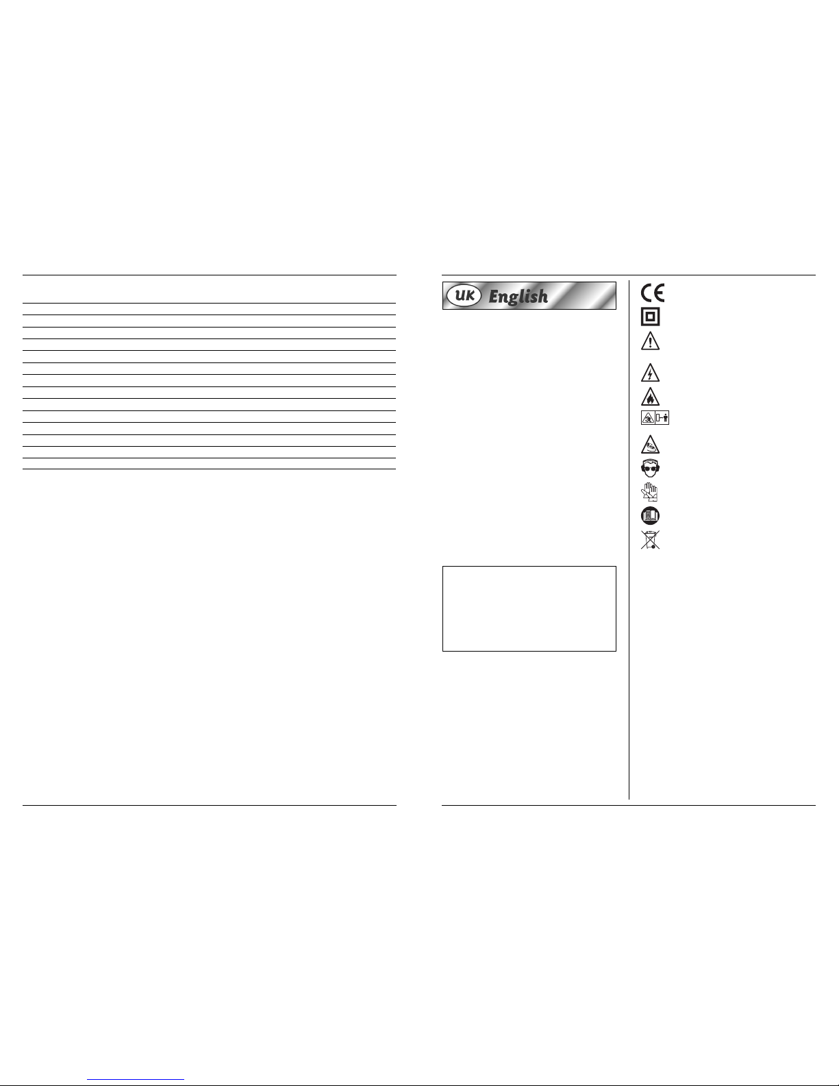
EXPLANATION OF SYMBOLS
In this manual and/or on the machine the following
symbols are used:
In accordance with essential applicable safety
standards of European directives
Class II machine – Double insulation – You don’t
need any earthed plug.
Denotes risk of personal injury, loss of life or
damage to the tool in case of non-observance of
the instructions in this manual.
Indicates electrical shock hazard.
Risk of fire
Keep bystanders away
Remove the plug from the mains
Wear safety glasses and ear protection
Wear protective gloves
Read instructions carefully
Faulty and/or discarded electrical or electronic
apparatus have to be collected at the appropriate
recycling locations.
SAFETY INSTRUCTIONS
When using electric machines always observe the
safety regulations applicable in your country to
reduce the risk of fire, electric shock and personal
injury. Read the following safety instructions and
also the enclosed safety instructions. Keep these
instructions in a safe place!
• Check that the maximum speed indicated on the
grinding disc corresponds to the maximum speed of
the machine. The speed of the machine must not
exceed the value on the grinding disc.
• Make sure that the dimensions of the grinding disc
correspond to the specifications of the machine.
• Make sure that the grinding disc has been mounted
and fastened properly. Do not use reducing rings or
adapters to make the grinding disc fit properly.
• Treat and store grinding discs in conformance with
the supplier’s instructions.
• Do not use the machine for grinding workpieces with
a maximum thickness exceeding the maximum
grinding depth of the grinding disc.
• Do not use grinding discs for deburring.
• When grinding discs have to be mounted on the
thread of the spindle, make sure that the spindle has
sufficient thread. Make sure that the spindle is
sufficiently protected and does not touch the
grinding surface.
Voltage | 230 V~
Frequency | 50 Hz
Power input | 2000 W
No-load speed | 6000/min
Disc diameter | 230 mm
Spindle dimension | M 14
Weight | 4,9 kg
Lpa (sound pressure) | 97,9 dB (A)
Lwa (sound power) | 110,9 dB (A)
Vibration value | 3,2 m/s
2
Ferm 3
Page 4
Ferm 37
• Before use, inspect the grinding disc for any damage.
Do not use grinding discs which are crack-ed, ripped
or otherwise damaged.
• Before use, let the machine run idle for 30 seconds.
Immediately switch off the machine in case of
abnormal vibrations or occurrence of another
defect. Carefully inspect the machine and grinding
disc before switching the machine on again.
• Make sure that sparks do not put people into danger
or that they contact highly flammable substances.
• Make sure that the workpiece is sufficiently
supported or clamped. Keep your hands away from
the surface to be cut.
• Always wear safety goggles and hearing protection. If
desired or required also use another kind of
protection like for example an apron or helmet.
• Ensure that mounted wheels and points are fitted in
accordance with the manufacturer’s instructions.
• Ensure that blotters are used when they are
provided with the bonded abrasive product and
when they are required.
• If a guard is supplied with the tool never use the tool
without such a guard.
• For tools intended to be fitted with threaded hole
wheel, ensure that the thread in the wheel is long
enough to accept the spindle length.
• Ensure that ventilation openings are kept clear when
working in dusty conditions. If it should become
nessesary to clear dust, first disconnect the tool
from the mains supply (use non metallic objects) and
avoid damaging internal parts.
• Though poor conditions of the electrical mains,
shortly voltage drops can appear when starting the
equipment. This can influence other equipment (eq.
blinking of a lamp). If the mains-impedance Zmax
<0.348 Ohm, such disturbances are not expected.
(In case of need, you may contact your local supply
authority for further information.
3. ASSEMBLY
Prior to mounting an accessory always unplug the
tool.
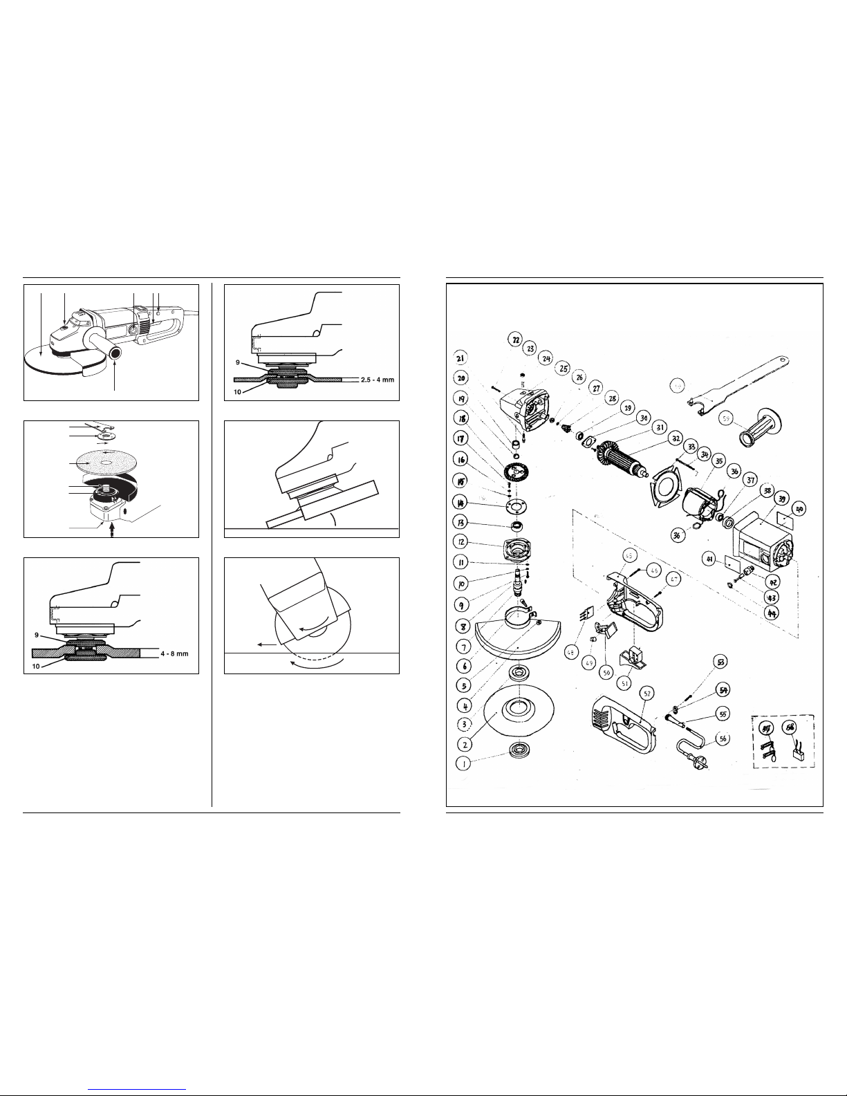
MOUNTING A GRINDING DISC.
Fig 2
Use grinding discs of the correct dimension. Use fibre
reinforced grinding discs only. The grinding disc must
not touch the edge of the guard.
• Press the spindle lock (6) and turn the spindle (9)
until it engages in the lock. Keep the spindle lock
pressed during this procedure.
• Remove the flange nut (12) from the spindle using the
spanner (11).
• Position the grinding disc (7) on the flange (5).
• Place the flange nut on the spindle an tighten it using
the spanner.
• Release the spindle lock and check that the spindle is
unlocked by rotating it.
MOUNTING THE SIDE HANDLE
Fig 1
The side handle can be used for both left-hand and righthand control.
• Fasten the side handle (Fig. 5) for left-hand operation
on the right-hand side of the machine.
• Fasten the side handle for right-hand operation on
the left-hand side of the machine.
• Fasten the side handle for upright working at the top
of the machine.
Make sure that the side handle is fastened
properly and cannot loosen unexpectedly.
MOUNTING GRINDING DISCS AND
ROUGHING DISCS
Fig. 3 and 4 show how to mount the flange (10) when
using thick (4 – 8 mm) and thin (2,5 – 4 mm) discs.
4. USE
SPECIAL ATTENTION WHEN STARTING
THE MACHINE
• Clamp the workpiece and make sure that the
workpiece cannot slide from under the machine
during the cutting activities.
• When working with the machine, always hold it firmly
with both hands and provide for a secure stance.
• Always direct the cable to the rear away from the
machine.
• Insert the mains plug only when the machine is
switched off.
• Apply the machine to the workpiece only when
switched on
Never use the machine for grinding magnesium
workpieces.
SWITCHING ON AND OFF
• This machine is equipped with a safety switch.
• Start the machine by pressing the “lock off” button
(to disengrage the switch) and switch on the
machine.
Before start working, the machine must be run
according to the max. speed.
OPERATION
• Hold the machine firmly and move it against the
workpiece. Move the grinding disc evenly across the
workpiece.
• Move the machine during roughing under an angle of
30º - 40º across the workpiece (fig. 5).
Never use grinding discs for roughing!
• The machine must always work opposite to the
direction of rotation. Therefore, never move the
machine in the other direction! Otherwise, the
danger exists of it being pushed uncontrolled out of
the cut (fig. 6).
• Inspect the grinding disc regularly. Worn discs have a
negative effect on efficiency of the machine. Replace
the grinding disc on time.
• Do not put the machine down when the motor is still
running. Do not place the machine on a dusty
surface. Dust particles may enter the mechanism.
4 Ferm
Page 5
36 Ferm
• Always switch off the machine first before removing
the plug from the wall socket.
Never use the spindle lock to stop the motor.
TROUBLESHOOTING
1. Machine fails to operate:
• Power turned off
• (Extension) cable damaged
2. The elektromotor hardly reaches maximum
speed:
• The extension cable is too thin and/or too long
• The mains voltage is lower than 230 V
3. Machine overheats:
• Air vents are blocked. Clean them with a dry cloth.
• The machine has been overloaded. Use the machine
for the purpose it is made for.
4. Excessive sparking or elektromotor runs
irregular.
• There’s dirt inside the motor or the carbon brushes
are worn. Replace the carbon brushes or bring the
machine to a specialized repair centre.
5. SERVICE & MAINTENANCE
MAINTENANCE
Make sure that the plug is removed from the mains when
carrying out maintenance work on the motor.
The Ferm machines have been designed to operate over
a long period of time with a minimum of maintenance.
Continuous satisfactory operation depends upon
proper machine care and regular cleaning.
CLEANING
Regularly clean the machine housing with a soft cloth,
preferably after each use. Keep the ventilation slots free
from dust and dirt. If the dirt does not come off use a soft
cloth moistened with soapy water. Never use solvents
such as petrol, alcohol, ammonia water, etc. These
solvents may damage the plastic parts.
LUBRICATION
The machine requires no additional lubrication.
FAULTS
Should a fault occur, e.g. after wear of a part, please
contact the service address on the warranty card. In the
back of this manual you find an exploded view showing
the parts that can be ordered.
ENVIRONMENT
To prevent damage during transport, the appliance is
delivered in a solid packaging which consists largely of
reusable material. Therefore please make use of options
for recycling the packaging.
Faulty and/or discarded electrical or electronic
apparatus have to be collected at the appropriate
recycling locations.
WARRANTY
The warranty conditions can be found on the separately
enclosed warranty card.
We declare under our sole responsibility that this
product is in conformity with the following standards or
standardized documents
EN 50144-1, EN50144-2-3,
EN 55014-1, EN 55014-2,
EN 61000-3-2, EN 61000-3-3
in accordance with the regulations.
98/37/EEC, 73/23/EEC
89/336/EEC
from 01-06-2005
ZWOLLE NL
W. Kamphof
Quality department
CE
ı
DECLARATION OF CONFORMITY
(UK)
Ferm 5
Page 6
Placér ikke maskinen på en støvet overflade.
Støvpartikler kan komme i kontakt med mekanikken.
• Sluk altid maskinen før du fjerner stikket fra
stikkontakten.
Anvend aldrig aksellåsen til stoppe motoren med.
HJÆLP
1. Maskinen fungere ikke:
• Strømmen er slukket
• (Forlænger) ledning er beskadiget
2. Den elektroniske motor når ikke op til
maksimumhastighed:
• Forlængerledningen er for tynd og/eller for lang
• Strømforsyningen er lavere end 230 V
3. Maskinen overophedes:
• Udluftningskanaler er blokeret. Rengør dem med en
tør klud.
• Maskinen er blevet overbelastet. Anvend kun
maskinen til det den er beregnet til.
4. Usædvanlig mange gnister, eller den
elektroniske motor køre uregelmæssigt.
• Der er snavs inde i motoren, eller kulbørsterne er
nedslidte. Udskift kulbørsterne eller aflevér
maskinen til et særligt reparationscenter.
5. SERVICE & VEDLIGEHOLDELSE
VEDLIGEHOLDELSE
Sørg for, at stikket til maskinen er taget ud af
stikkontakten, når der skal udføres vedligeholdelse på
motoren.
Ferm maskiner er blevet konstrueret, så de kan arbejde i
længere perioder med et minimum af vedligeholdelse.
Korrekt vedligeholdelse og rengøring af maskinen er en
forudsætning for lang tids tilfredsstillende brug.
RENGØRING
Kappen omkring motoren skal rengøres med en blød
klud, helst hver gang maskinen har været brugt.
Ventilationsrillerne skal holdes fri for støv og snavs. Hvis
snavset ikke vil gå af, bruges en blød klud vredet op i
sæbevand. Der må ikke bruges opløsningsmidler som
f.eks. benzin, sprit, salmiakspiritus o.l. Sådanne
opløsningsmidler kan beskadige dele af plastic.
SMØRING
Maskinen skal ikke smøres.
FEJL
Skulle en fejl opstå, f.eks. pga. slidtage af en enhed,
kontakt venligst serviceadressen på garantibeviset. På
bagsiden af denne manual finder du en tegning med alle
dele, der kan bestilles.
MILJØ
For at undgå transportbeskadigelse leveres maskinen i
en solid emballage. Emballagen er så vidt muligt lavet af
genbrugsmateriale. Genbrug derfor emballagen.
Defekte og/eller kasserede elektriske eller
elektroniske maskiner skal afleveres på en
genbrugsplads.
GARANTI
Garantibetingelser er beskrevet på det separat vedlagte
garantibevis.
Vi erklærer herved, udelukkende på eget ansvar, at dette
produkt opfylder følgende standarder eller
standardiserede dokumenter
EN 50144-1, EN50144-2-3,
EN 55014-1, EN 55014-2,
EN 61000-3-2, EN 61000-3-3
i henhold til følgende direktiver:
98/37/EØF, 73/23/EØF
89/336/EØF
01-06-2005
ZWOLLE NL
W. Kamphof
Quality department
CE
ı
KONFORMITETSERKLÆRING
(DK)
Ferm 35
DIE NUMMERN IM NACHFOLGENDEN TEXT
KORRESPONDIEREN MIT DEN ABBILDUNGEN
AUF SEITE 2
WINKELSCHLEIFER
INHALT
1. Gerätedaten
2. Sicherheitshinweise
3. Wartungs- und Verschleißteile
4. Bedienung
5. Wartung und Pflege
1. GERÄTEDATEN
EINFÜHRUNG
Dieses Gerät wurde zum Schruppen und Schlichten von
Metall- und Steinoberflächen entwickelt.
LIEFERUMFANG
1 Winkelschleifer
1 Seitengriff
1 Schraubenschlüssel
2 Trennscheibe
1 Satz Kohlebürsten
1 Bedienungsanleitung
1 Sicherheitsvorschriften
1 Garantiekarte
TECHNISCHE DATEN
TEILEBEZEICHNUNG
Abb.1
1 Ein-/Aus-Schalter
2 Schraubdeckel Kohlebürste (Beidseitig)
3 Spindelarretierung
4 Schleifscheibe
5 Seitengriff
6. “Lock-off” Knopf
2. SICHERHEIT
ERLÄUTERUNG DER SYMBOLE
In dieser Anleitung und/oder auf dem Gerät werden
folgende Symbole verwendet:
Übereinstimmung mit den jeweils maßgeblichen
EU-Sicherheitsrichtlinien
Gerät der Schutzklasse II – schutzisoliert – kein
Schutzkontakt erforderlich
Lebens- und Verletzungsgefahr und Gefahr von
Beschädigungen am Gerät bei Nichteinhaltung der
Sicherheitsvorschriften in dieser Anleitung.
Elektroschockgefahr.
Brandgefahr
Umstehende fernhalten
Stecker aus der Netzsteckdose ziehen
Schutzbrille und Gehörschutz tragen
Schutzhandschuhe tragen
Anweisungen sorgfältig lesen
Schadhafte und/oder entsorgte elektrische oder
elektronische Geräte müssen an den dafür
vorgesehenen Recycling-Stellen abgegeben werden.
SICHERHEITSVORSCHRIFTEN
Beachten beim Benutzen von Elektromaschinen
immer die örtlichen Sicherheitsvor-schriften
bezüglich Feuerrisiko, Elektroschock und
Verletzung. Lesen Sie außer den folgenden
Hinweisen ebenfalls die Sicherheitsvorschriften im
einschlägigen Sonderteil.
Die Hinweise müssen sicher aufbewahrt werden!
• Überprüfen Sie, ob die Höchstdrehzahl, die auf der
Schleifscheibe angegeben ist, mit der
Höchstdrehzahl der Maschine übereinstimmt. Die
Drehzahl der Maschine darf nicht höher sein als der
Wert auf der Schleifscheibe.
• Achten Sie darauf, daß die Abmessungen der
Schleifscheibe mit den Angaben der Maschine
übereinstimmen.
• Achten Sie darauf, daß die Schleifscheibe richtig
montiert und ordnungsgemäß festgesetzt wurde.
Verwenden Sie keine Reduzierringe oder Adapter,
um die Schleifscheibe passend zu machen.
• Behandeln und lagern Sie Schleifscheiben gemäß den
Vorschriften des Lieferanten.
• Verwenden Sie die Maschine nicht, um Werkstücke
durchzuschleifen, die dicker sind als die maximale
Schleiftiefe der Schleifscheibe.
• Verwenden Sie keine Schleifscheiben für
Abgratarbeiten.
Spannung | 230 V~
Frequenz | 50 Hz
Eingangsspannung | 2000 W
Leerlaufdrehzahl | 6000/min
Schleifscheibe ø | 230 mm
Schleifspindelgewinde | M 14
Gewicht | 4,9 kg
Lpa (Schalldruckpegel) | 97,9 dB(A)
Lwa (Schallleistungspegel) | 110,9 dB(A)
Vibrationswert | 3,2 m/s
2
6 Ferm
Page 7

Forvis dig om, at spindlen er godt afskærmet og ikke
kan komme i kontakt med slibeoverfladen.
• Inden anvendelse skal slibeskiven kontrolleres for
eventuelle skader. Brug ikke revne eller brudte
slibeskiver eller sådanne skiver, der på anden måde
er beskadiget.
• Lad maskinen køre ubelastet i 30 sekunder inden
brug. Sluk øjeblikkeligt for maskinen, når den
begynder at vibrere for meget eller når der opstår en
anden defekt. Kontrollér maskinen og slibeskiven
omhyggeligt, før du igen tænder for maskinen.
• Sørg for, at den eventuelle gnistregn fra slibeskiven
ikke er til fare for mennesker og at den ikke kommer i
kontakt med letantændelige stoffer.
• Sørg for, at arbejdsemnet understøttes tilstrækkeligt
eller at det klemmes ind. Hold hænderne væk fra
slibeoverfladen.
• Bær altid sikkerhedsbriller og høreværn. Brug om
ønsket eller om nødvendigt andre
beskyttelsesmidler såsom et forklæde eller en hjelm.
• Kontrollér, at hjul og punkter er monteret i
overensstemmelse med producentens anvisninger.
• Kontrollér, at der bruges filtre, når de leveres med
den bundne slibeskive, og når det er påkrævet.
• Hvis værktøjet leveres med afskærmning, må det
ikke benyttes uden brug af denne afskærmning.
• Ved anvendelse af værktøjer, der skal påmonteres
gevindskårne hjul, skal det kontrolleres, at gevindet i
hjulet er langt nok til spindlen.
• Kontrollér, at ventilationsåbningerne holdes fri ved
arbejde under støvede forhold. Hvis det er
nødvendigt at rengøre for støv, skal maskinen først
afbrydes fra forsyningsnettet (brug ikke
metalobjekter). Undgå at beskadige indvendige dele.
• Hvis der er fejl på ledningsnettet, kan der ske
spændingsfald ved start af udstyret. Det kan påvirke
andet udstyr (f.eks. en lampe, der blinker). Hvis
netimpedansen Zmaks. < 0,348 Ohm, forventes der
ikke sådanne forstyrrelser. Yderligere oplysninger
fås ved henvendelse til det lokale elforsyningsselskab.
3. SAMLING
Før montering af tilbehør skal værktøjet altid være
strømafbrudt
MONTERING AF SIDEHÅNDGREBET
Fig 2
Anvend slibeskiver med den rette størrelse. Anvend
udelukkende fiberforstærkede slibeskiver. Slibeskiven
må ikke komme i kontakt med beskyttelseskappens
kant.
• Tryk aksellåsen (6) ind, og drej akslen (9) til denne
falder i låsen. Hold aksellåsen indtrykt, sålænge De
følger denne procedure.
• Fjern flangemøtrikken (12) fra akslen ved hjælp af
klampernøglen (11).
• Placér slibeskiven (7) på flangen (5).
• Skru flangemøtrikken på akslen igen og drej den fast
ved hjælp af klampernøglen.
• Kontrollér, at spærreanordningen er frigjort ved at
dreje på akslen og slip herved aksellåsen.
MONTAGE AF SIDEHÅNDGREB
Fig 1
Sidehåndgrebet er egnet til såvel venstrehåndet som
højrehåndet betjening.
• Ved venstrehåndet betjening drejes sidehåndgrebet
(Fig. 5) i optagelsen på maskinens højre side.
• Ved højrehåndet betjening drejes sidehåndgrebet i
optagelsen på maskinens venstre side.
• Ved vertikale arbejder drejes sidehåndgrebet i
optagelsen på maskinens overkant.
Sørg for, at sidehåndgrebet sidder godt fast og ikke
uventet kan rystes løs
MONTERING AF SLIBESKIVER OG
SKÆRESKIVER
Fig. 3 og 4 demonstrerer montering af flangen (10), når
der anvendes tykke (4 – 8 mm) og tynde (2.5 – 4 mm)
skiver.
4. ANVENDELSE
SÆRLIGE FORHOLDSREGLER VED START
AF MASKINEN
• Fastgør arbejdsstykket, og sørg for at arbejdsstykket
ikke glider ind under maskinen under betjening.
• Når der arbejdes med maskinen skal den altid holdes
med et fast greb med begge hænder, og du bør stå på
et sikkert underlag.
• Hold altid ledningen bort, væk fra maskinen.
• Indsæt kun strømledningen når maskinen er slukket.
• Maskine og arbejdsstykke bør ikke komme i kontakt,
når maskinen er slukket.
Anvend aldrig maskinen til at slibe arbejdsstykker i
magnesium.
IND/UDKOBLING
• Denne maskine er udstyret med en sikkerhedsafbryder.
• Maskinen startes ved at trykke på knappen "udløs" (for at
udløse afbryderen) og starte maskinen
.
Når maskinen har nået det maksimale omdrejningstal, kan den skubbes frem over arbejdsemnet
BETJENING
• Hold maskinen med et fast greb, og fjern denne fra
arbejdsstykket. Bevæg slibeskiven med ens
bevægelser over arbejdsstykket.
• Bevæg maskinen under slibning med en vinkel på 30º 40º tværs over arbejdsstykket (fig.5).
Anvend aldrig slibeskiven til grovhugning!
• Maskinen skal altid arbejde modsat
rotationsretningen. Træk derfor ikke maskinen i den
modsatte retning! Ellers kan den skubbes tilbage, væk
fra snittet, ude af kontrol
• Efterse ofte slibeskiven. Nedslidte skiver har en
negativ virkning på maskinens effektivitet. Udskift
slibeskiven i god tid.
• Stil ikke maskinen ned når motoren stadig køre.
34 Ferm
• Sorgen Sie dafür, daß bei Verwendung von
Schleifscheiben, die auf dem Gewinde der Spindel
befestigt wird, die Spindel genügend Gewinde hat.
Sorgen Sie dafür, daß die Spindel ausreichend
geschützt ist und die Schleifoberfläche nicht berührt.
• Überprüfen Sie die Schleifscheibe vor Benutzung auf
eventuelle Beschädigungen. Verwenden Sie keine
Schleifscheiben, die geborsten, gerissen oder anders
beschädigt sind.
• Lassen Sie die Maschine vor Inbetriebnahme 30
Sekunden lang unbelastet laufen. Schalten Sie die
Maschine sofort aus, wenn diese deutlich zu zittern
anfängt oder wenn ein anderer Defekt auftritt.
Überprüfen Sie die Maschine und Schleifscheibe
gründlich, bevor Sie die Maschine erneut einschalten.
• Sorgen Sie dafür, daß ein eventueller Funkenregen
keine Gefahr für Personen bildet oder in Richtung
von leicht entflammbaren Substanzen spritzt.
• Sorgen Sie dafür, daß das Werkstück ausreichend
unterstützt oder eingeklemmt wird. Bleiben Sie mit
den Händen von der Schleiffläche fern.
• Tragen Sie immer eine Schutzbrille und einen
Hörschutz. Benutzen Sie, falls erforderlich oder
gewünscht, andere Schutzkleidung, wie z.B. eine
Schürze oder einen Helm.
• Befestigen Sie Scheiben und sonstige Einzelteile
gemäß den Vorschriften des Herstellers.
• Verwenden Sie falls erforderlich Fließpapier, wenn
diese mit den Schleifmitteln mitgeliefert worden sind.
• Verwenden Sie immer eine Sicherheitsvorrichtung,
wenn diese mit dem Gerät mitgeliefert worden ist.
• Bei Werkzeugen, die mit einer Lochscheibe mit
Gewinde ausgerüstet werden, muss das Gewinde in
der Bohrung für die Spindellänge lang genug sein.
• Achten Sie darauf, dass Lüftungsöffnungen bei der
Arbeit in staubiger Umge-bung nicht verschmutzt
sind. Bevor Sie Lüftungsöffnungen reinigen, ziehen
Sie den Netzstecker. Verwenden Sie zum Reinigen
keine Metallgegenstände, vermeiden Sie die
Beschädigung von Innenteilen.
• Bei einem schwachen Stromnetz kann es beim
Einschalten der Anlage zur Span-nungsabsenkung
kommen. Dies kann sich auf andere Geräte
auswirken (beispielsweise Blinken einer
Anzeigelampe). Solche Störungen sind
ausgeschlossen, wenn die Netzimpedanz Zmax <
0,348 Ohm beträgt. Im Zweifelsfall fragen Sie bei
Ihrem Ver-sorgungsbetrieb nach.
3. MONTAGE
Vor Befestigung von Zubehör muss immer der
Stecker des Werkzeugs gezogen werden.
EINSETZEN EINER SCHLEIFSCHEIBE
Abb.2
Arbeiten Sie mit Schleifscheiben mit den richtigen
Abmessungen. Benutzen Sie nur glasfaserverstärkte
Schleifscheiben. Die Schleifscheibe darf den Rand der
Schutzkappe nicht berühren.
• Drücken Sie die Spindelverriegelung (6) und drehen
Sie die Spindel (9) bis diese einrastet. Halten Sie die
Verriegelung gedrückt, solange Sie hiermit tätig sind.
• Lösen Sie mit Hilfe des Spannschlüssels (11) die
Flanschmutter (12) vom Spindel.
• Setzen Sie die Schleifscheibe (7) auf die Flansche (5).
• Drehen Sie die Flanschmutter zurück auf die Spindel
und ziehen Sie sie anschließend mit dem
Spannschlüssel an.
• Lassen Sie die Spindelverriegelung los und
überprüfen Sie, ob die Verriegelung aufgehoben
wurde, indem Sie an der Spindel drehen.
MONTIEREN DES SEITENGRIFFS
Abb.1
Der Seitengriff eignet sich für links- und rechtshändige
Bedienung.
• Drehen Sie zwecks linkshändige Bedienung den
Seitengriff (Abb. 5) in die Aufnahme rechts der
Maschine.
• Drehen Sie zwecks rechtshändige Bedienung den
Seitengriff in die Aufnahme links der Maschine.
• Drehen Sie zwecks vertikaler Arbeiten den
Seitengriff in die Aufnahme oben in der Maschine.
Achten Sie auf einen festen Sitz des Seitengriffs,
damit dieser sich durch Vibration nicht unerwartet
löst.
EINSETZEN VON SCHLEIF- UND
SCHRUPPSCHEIBEN
In Abb. 3 und 4 ist dargestellt, wie der Flansch (10) bei
Verwendung von dicken (4–8 mm) und dünnen (2,5–4
mm) Scheiben angebracht wird.
4. GEBRAUCH
VORSICHTSMAßNAHMEN BEIM STARTEN
DES GERÄTS
• Das Werkstück immer festklemmen, sodass es
während der Arbeit nicht unter dem Gerät weg
schieben kann.
• Beim Arbeiten das Gerät immer mit beiden Händen
gut festhalten und für einen sicheren Stand sorgen.
• Das Kabel immer nach hinten vom Gerät weg führen.
• Den Netzstecker nur bei ausgeschaltetem Gerät
einstecken.
• Das Gerät nur dann auf dem Werkstück ansetzen,
wenn es eingeschaltet ist.
Das Gerät darf nie zum Schleifen von
Werkstücken aus Magnesium verwendet werden.
EIN- UND AUSSCHALTEN
•
Diese Maschine ist mit einem Sicherheitsschalter
ausgerüstet.
• Starten Sie die Maschine, indem Sie den "lock-off"-Knopf
betätigen (hierdurch wird der Schalter entsichert) und die
Maschine einschalten.
Warten Sie mit dem Schleifen bis die Maschine das
normale Tempo erreicht hat.
BEDIENUNG
• Das Gerät gut festhalten und gegen das Werkstück
bewegen. Die Schleifscheibe gleichmäßig über die
Werkstückoberfläche bewegen.
Ferm 7
Page 8

TALLENE I DEN FØLGENDE TEKST
KORRESPONDERER MED AFBILDNINGERNE PÅ
SIDE 2
VINKELSLIBER
INDHOLD:
1. Maskindata
2. Sikkerhedsforskrifter
3. Samling
4. Anvendelse
5. Service & vedligeholdelse
1. MASKINDATA
INDLEDNING
Denne maskine er udviklet til at skære og slibe i metal og
sten.
PAKKEINDHOLD
1 Skærebrænder
1 Sidehåndgreb
1 Skruenøgle
2 Skæringsvinkelsliber
1 Sæt kulbørster
1 Instruktionsmanual
1 Sikkerhedsinstruktioner
1 Garantibevis
TEKNISKE SPECIFIKATIONER
PRODUKTINFORMATION
Fig. 1
1. ænd/sluk-kontakt
2. gevindsokkel kulbørste (begge sider)
3. aksellås
4. slibeskive
5. sidehåndgreb
6. knappen "udløs"
2. SIKKERHEDSINSTRUKTIONER
SYMBOLFORKLARING
I denne brugervejledninge og/eller på maskinen
anvendes der følgende piktogrammer:
I overensstemmelse med grundlæggende
sikkerhedsstandarder i de europæiske direktiver.
Klasse II maskine – Dobbelt isolering – Du behøver
ingen jordforbindelsestik.
Betegnelse for risiko for personskader, dødsfald
eller beskadigelse af værktøjet i tilfælde af at du er
uopmærksom på instruktioner i denne manual.
indikerer farer for elektrisk stød
Brandfare
hold tilstedeværende på afstand.
Fjern stikket fra kontakten.
Bær beskyttelsesbriller og høreværn
Bær beskyttelseshandsker
Læs instruktionerne omhyggeligt
Defekte og/eller kasserede elektriske eller
elektroniske maskiner skal afleveres på en
genbrugsplads.
SIKKERHEDSFORSKRIFTER
Ved anvendelse af elektriske maskiner skal man altid
følge de lokalt gældende sikkerhedsforskrifter i
forbindelse med brandfare, fare for elektrisk stød og
legemensbeskadigelse. Læs udover de nedenstående
instruktioner også sikkerhedsforskrifterne i den
separat vedlagte sikkerhedsfolder.
Bevar instruktionerne godt!
• Kontrollér, at det maksimale omdrejningstal, der er
angivet på slibeskiven, stemmer overens med
maskinens maksimale omdrejningstal. Maskinens
omdrejningstal må ikke være højere end den på
slibeskiven angivne værdi.
• Vær opmærksom på, at slibeskivens mål stemmer
overens med maskinens specifikationer.
• Vær opmærksom på, at slibeskiven er monteret
rigtigt og ordentligt spændt fast. Brug ikke
reduktionsringe eller adaptere for at få en slibeskive
til at passe.
• Brug og opbevar slibeskiver i henhold til
leverandørens anvisninger.
• Brug ikke maskinen til gennemslibning af
arbejdsemner med en tykkelse, der er større end
skæreskivens maksimale slibedybde.
• Brug ikke skæreskiver til afgratning.
• Ved anvendelse af slibeskiver, der fastspændes på
spindlens gevind, skal der sørges for at spindlen har
et tilstrækkeligt stort gevind.
Spænding | 230 V~
Frekvens | 50 Hz
Optaget effekt | 2000 W
Ubelastet hastighed | 6000/min
Skive diameter | 230 mm
Akseldimension | M 14
Vægt | 4,9 kg
Lpa (Lydtryk) | 97,9 dB (A)
Lwa (Lydevne) | 110,9 dB (A)
Vibrationsværdi | 3,2 m/s
2
Ferm 33
• Zum Schruppen das Gerät in einem Winkel von 30º
bis 40º über das Werkstück führen (Abb. 5).
Nie eine Schleifscheibe zum Schruppen
verwenden!
• Das Gerät muss immer gegen die Drehrichtung
arbeiten. Deshalb mit dem Gerät nicht in die andere
Richtung fahren! Sonst besteht die Gefahr, dass es
unkontrolliert aus dem Schnitt gedrückt wird (Abb.
6).
• Die Schleifscheibe muss regelmäßig überprüft
werden. Verschlissene Scheiben beeinträchtigen die
Wirkung des Werkzeugs. Die Schleifscheibe
rechtzeitig auswechseln.
• Bei laufendem Motor darf das Gerät nie abgelegt
werden. Das Gerät nicht auf eine staubige
Oberfläche legen, da sonst Staubpartikel in die
Mechanik eindringen können.
• Ehe der Stecker aus der Steckdose gezogen wird,
muss das Gerät ausgeschaltet werden.
Der Motor darf nie mittels der Spindelarretierung
angehalten werden.
FEHLERBEHEBUNG
1. Das Gerät funktioniert nicht:
• Der Strom ist ausgeschaltet
• Beschädigtes (Verlängerungs-) Kabel
2. De Elektromotor erreicht die maximale
Drehzahl kaum:
• Zu dünnes und/oder zu langes Verlängerungskabel
• Netzspannung von weniger als 230 V
3. Das Gerät wird überhitzt:
• Verstopfte Lüftungsschlitze, Schlitze mit einem
trockenen Tuch reinigen
• Überlastung des Geräts, das Gerät nur wie
vorgesehen gebrauchen
4. Zu viel Funkenbildung oder unregelmäßig
laufender Elektromotor
• Verschmutzungen im Motor oder verschlissene
Kohlebürsten, die Kohlebürsten auswechseln oder
das Gerät bei einer Fachwerkstatt zur Reparatur
geben
5. SERVICE UND WARTUNG
WARTUNG
Vergewissern Sie sich, dass der Netzstecker gezogen ist,
während Sie Wartungsarbeiten am Motor ausführen.
Die Ferm-Geräte wurden für Langzeitbetrieb bei
minimaler Wartung konstruiert. Ihr nachhaltig
zufriedenstellender Betrieb hängt von der richtigen
Gerätepflege und von regelmäßiger Reinigung ab.
REINIGUNG
Reinigen Sie das Gerätegehäuse regelmäßig mit einem
weichen Tuch, vorzugsweise nach jeder Benutzung.
Halten Sie die Belüftungsschlitze frei von Staub und
Schmutz.
Lässt sich der Schmutz so nicht entfernen, verwenden
Sie ein weiches, mit Seifenwasser befeuchtetes Tuch.
Verwenden Sie niemals Lösungsmittel wie Benzin,
Alkohol, Ammoniakwasser usw. Diese Lösungsmittel
können die Kunststoffteile beschädigen.
SCHMIERUNG
Das Gerät erfordert keine zusätzliche Schmierung.
FEHLER
Sollte beispielsweise nach Abnutzung eines Teils ein
Fehler auftreten, dann setzen Sie sich bitte mit der auf
der Garantiekarte angegebenen Serviceadresse in
Verbindung. Im hinteren Teil dieser Anleitung befindet
sich eine ausführliche Übersicht über die Teile, die
bestellt werden können.
UMWELT
Um Transportschäden zu verhindern, wird die Maschine
in einer soliden Verpackung geliefert. Die Verpackung
besteht weitgehend aus verwertbarem Material.
Benutzen Sie also die Möglichkeit zum Recyclen der
Verpackung.
Schadhafte und/oder entsorgte elektrische oder
elektronische Geräte müssen an den dafür
vorgesehenen Recycling-Stellen abgegeben werden.
GARANTIE
Die Garantiebedingungen finden Sie auf der lose
beigefügten Garantiekarte.
Wir erklären unsere alleinige Verantwortung, dass
dieses Produkt konform den nachstehenden Standards
oder standardisierten Dokumenten ist.
EN 50144-1, EN50144-2-3,
EN 55014-1, EN 55014-2,
EN 61000-3-2, EN 61000-3-3
Gemäß den Vorschriften.
98/37/EWG, 73/23/EWG
89/336/EWG
vom 01-06-2005
ZWOLLE NL
W. Kamphof
Quality Department
CE
ı
KONFORMITÄTSERKLÄRUNG
(D)
8 Ferm
Page 9

FEILSØKING
1. Maskinen går ikke:
• Maskinen er slått av
• Ledning eller skjøteledning er skadet
2. Elektromotoren oppnår ikke full hastighet:
• Skjøteledningen er for tynn eller for lang
• Strømspenningen er lavere enn 230 V
3. Maskinen blir for varm:
• Lufteventilene er blokkert. Rengjør dem med en tørr
klut.
• Maskinen er overbelastet. Bruk maskinen bare til det
den er beregnet for.
4. Alt for mye gnister, eller elektromotoren går
ujevnt
• Det er skitt i motoren, eller så er kullbørstene utslitt.
Skift kullbørstene eller lever maskinen hos et
spesialisert reparasjonsverksted.
5. SERVICE OG VEDLIKEHOLD
VEDLIKEHOLD
Trekk støpselet ut av stikkontakten når det skal utføres
vedlikehold på motoren.
Maskinene fra Ferm er konstruert for å kunne brukes
over lang tid med minimalt vedlikehold. For å oppnå
tilfredsstillende resultater over lang tid, er det viktig å
stelle maskinen riktig og rengjøre den regelmessig.
RENGJØRING
Rengjør maskinens ytterside regelmessig med en myk
fille - helst hver gang den er brukt. Hold
ventilasjonsåpningene frie for støv og skitt. Hvis det er
vanskelig å fjerne skitt, kan man bruke en myk fille som er
fuktet med såpevann. Bruk aldri løsemidler som bensin,
alkohol, ammoniakkvann, etc. Disse løsemidlene kan
ødelegge plastdelene.
SMØRING
Maskinen trenger ikke ekstra smøring.
FEIL
Hvis det oppstår feil som følge av for eksempel utslitte
deler, skal du kontakte serviceadressen på
garantikortet. Bakerst i denne bruksanvisningen finner
du en splittegning som viser deler som kan bestilles.
MILJØ
For å unngå transportskader leveres maskinen i solid
emballasje. Emballasjen er i den grad dette er mulig
fremstilt av resirkulerbart materiale. Benytt derfor
anledningen til å resirkulere emballasjen.
Defekte og/eller kasserte elektriske eller
elektroniske apparater må avhendes ved egnete
returpunkter.
GARANTI
Garantibetingelsene gjengis på det vedlagte, separate
garantikortet.
Vi erklærer på eget ansvar at dette produktet er i
samsvar med følgende standarder eller standardiserte
dokumenter.
EN 50144-1, EN50144-2-3,
EN 55014-1, EN 55014-2,
EN 61000-3-2, EN 61000-3-3
i samsvar med bestemmelsene.
98/37/EEC, 73/23/EEC
89/336/EEC
fra 01-06-2005
ZWOLLE NL
W. Kamphof
Kvalitetsavdelingen
CE
ı
ERKLÆRING AV ANSVARSFORHOLD
(N)
32 Ferm
DE NUMMERS IN DE NU VOLGENDE TEKST
VERWIJZEN NAAR DE AFBEELDINGEN OP
PAGINA 2
HAAKSE SLIJPER
INHOUDSOPGAVE:
1. Machine gegevens
2. Veiligheid
3. Montage accessoires
4. Bediening
5. Service & Onderhoud
1. MACHINE GEGEVENS
INTRODUCTIE
Deze machine is gemaakt voor het doorslijpen en
afbramen van metaal en steen.
INHOUD VAN DE VERPAKKING
1 Haakse slijper
1 Zijhandgreep
1 Spansleutel
1 Set koolborstels
2 Doorslijpschijven
1 Gebruiksaanwijzing
1 Veiligheidskatern
1 Garantiekaart
TECHNISCHE SPECIFICATIE
BENAMING ONDERDELEN
Fig.1
1. aan/uit-schakelaar
2. schroefdeksel koolborstel (aan weerskanten)
3. spindelblokkeerknop
4. slijpschijf
5. zijhandgreep
6. “lock-off” knop
2. VEILIGHEID
VERKLARING VAN DE SYMBOLEN
In deze handleiding en/of op deze machine worden de
volgende symbolen gebruikt:
CE Conform de Europese toepasselijke standaards
op het gebied van veiligheid
De machine is dubbel geïsoleerd overeenkomstig
EN50144; een aardedraad is daarom niet nodig
Gevaar voor lichamelijk letsel of materiele schade
Gevaar: elektrische spanning
Brandgevaar
Houd omstanders op afstand
Neem de stekker uit het stopcontact
Draag een veiligheidsbril en gehoorbescherming
Draag veiligheidshandschoenen
Lees de instructies
Defecte en/of afgedankte elektrische of
elektronische gereedschappen dienen ter
verwerking te worden aangeboden aan een
daarvoor verantwoordelijke instantie.
VEILIGHEIDSVOORSCHRIFTEN
Neem bij het gebruik van elektrische machines altijd
de plaatselijk geldende veiligheidsvoorschriften in
acht in verband met brandgevaar, gevaar voor
elektrische schokken en lichamelijk letsel. Lees
behalve onderstaande instructies ook de
veiligheidsvoorschriften in het apart bijgevoegde
veiligheidskatern door.
Bewaar de instructies zorgvuldig!
• Controleer of het maximum toerental dat op de
slijpschijf staat aangegeven, overeenkomt met het
maximum toerental van de machine. Het toerental
van de machine mag niet hoger zijn dan de waarde op
de slijpschijf.
• Let op dat de afmetingen van de slijpschijf
overeenkomen met de specificaties van de machine.
• Let op dat de slijpschijf juist is gemonteerd en naar
behoren is vastgezet. Gebruik geen ver-loopringen
of adapters om een slijpschijf passend te maken.
• Behandel en bewaar slijpschijven volgens de
voorschriften van de leverancier.
• Gebruik de machine niet voor het doorslijpen van
werkstukken met een dikte die groter is dan de
maximale slijpdiepte van de doorslijpschijf.
• Gebruik geen doorslijpschijven voor
afbraamwerkzaamheden.
Spanning | 230 V~
Frequentie | 50 Hz
Opgenomen vermogen | 2000 W
Toerental onbelast | 6000/min
Schijfdiameter | 230 mm
Spindelmaat | M 14
Gewicht | 4,9 kg
Lpa (geluidsdruk) | 97,9 dB (A)
Lwa (geluidsvermogen) | 110,9 dB (A)
Vibratiewaarde | 3,2 m/s
2
Ferm 9
Page 10

• La maskinen gå i 30 sekunder uten belastning før den
tas i bruk. Slå av maskinen øyeblikkelig hvis den
begynner å vibrere unaturlig mye eller hvis det viser
seg at den er defekt på en annen måte. Kontroller
maskinen og slipeskiva grundig før du starter
maskinen på nytt.
• Pass på at det eventuelle gnistregnet ikke kan være til
fare for mennesker i nærheten og at gnistregnet ikke
spruter i retning av lett antennelige stoffer.
• Pass på at arbeidsstykket er tilstrekkelig godt støttet
opp eller klemt fast. Hold hendene borte fra den
flaten som skal slipes.
• Bruk alltid vernebriller og hørselsvern. Bruk gjerne
annet verneutstyr også, som for eksempel
verneforkle eller hjelm, og alltid når det er påkrevet.
• Pass på at monterte slipeskiver og •hoder er festet i
samsvar med produsentens instruksjoner.
• Pass på at festeskiver brukes når slike festeskiver
følger med slipeproduktene og når det ellers kreves.
• Hvis verktøyet leveres med vernehette, må
verktøyet aldri brukes uten denne vernehetten.
• For verktøy som bruker slipeskiver som festes med
gjenger, må du passe på at gjengene i skiven er så
lange at hele spindelen skrus inn.
• Pass på at ventilasjonsåpningene ikke blokkeres når
verktøyet brukes på steder med mye støv. Hvis
verktøyet må rengjøres for støv, må verktøyet først
kobles fra strømnettet. Ikke bruk metalliske
objekter til å rengjøre verktøyet, og unngå å skade
interne deler.
• Hvis strømnettet er i dårlig forfatning, kan det oppstå
kortvarige spenningsfall når vinkelsliperen startes.
Dette kan virke inn på annet utstyr (for eksempel kan
lamper blinke). Hvis nettimpedansen er mindre enn
0,348 ohm, skal det vanligvis ikke oppstå slike
forstyrrelser. (Hør med din lokale forhandler hvis du
har behov for mer informasjon).
3. MONTERING
Trekk alltid ut støpslet før du monterer tilbehør.
MONTERING AV SIDEHÅNDTAKET
Fig 2
Bruk slipeskiver med riktig størrelse. Bruk kun
fiberforsterkede slipeskiver. Slipeskiven må ikke komme
i kontakt med kanten av vernehetten.
• Trykk inn spindellåsen (6) og vri spindelen (9) til
denne faller i låsen. Hold spindellåsen inntrykket så
lenge denne prosedyren følges.
• Fjern flensmutteren (12) fra spindelen ved hjelp av
spennøkkelen (11).
• Plasser slipeskiven (7) på flensen (5).
• Skru flensmutteren på spindelen igjen og stram den
med spennøkkelen.
• Løsne spindellåsen og kontroller om sperringen er
opphevet ved dreie på spindelen.
MONTERING AV SIDEHÅNDTAKET
Fig 1
Sidehåndtaket er egnet til både venstre- og
høyrehåndsbruk.
• Ved venstrehåndsbruk skrus sidehåndtaket (Fig. 5) i
åpningen på høyre side av maskinen.
• Ved høyrehåndsbruk skrus sidehåndtaket i åpningen
på venstre side av maskinen.
• For vertikal arbeide skrus sidehåndtaket i åpningen
på oversiden av maskinen.
Sørg for at sidehåndtaket sitter godt fast slik at det
ikke uventet kan ristes løs.
SETTE PÅ SLIPE- OG FRESESKIVER
Figur 3 og 4 viser montering av flensen (10) ved bruk av
tykk (4-8 mm) og tynn (2,5-4 mm) skive.
4. BETJENING
VÆR OPPMERKSOM PÅ DETTE NÅR
MASKINEN STARTES:
• Spenn fast arbeidsstykket og forsikre deg om at det
ikke kan skli fram under arbeidet.
• Hold maskinen godt fast med begge hender og innta
en trygg arbeidsstilling.
• Legg alltid ledningen bakover og bort fra maskinen.
• Maskinen må være avslått når du setter inn støpslet.
• Maskinen må være slått på når du legger an mot
arbeidsstykket.
Bruk aldri maskinen til sliping av magnesium.
INN-/UTKOPLING
• Denne maskinen har en sikkerhetsbryter.
• Start maskinen ved å trykke på knappen "slå av lås" (for å
frigjøre bryteren) og slå maskinen på.
Når apparatet har nådd det høyeste turtallet, kan
du skyve det over arbeidsstykket.
BRUK
• Hold maskinen godt fast, og beveg den mot
arbeidsstykket. Før slipeskiven jevnt over
arbeidsstykket.
• Ved fresing beveges maskinen over arbeidsstykket
med en vinkel på 30º-40º (fig. 5).
Bruk aldri slipeskiver til fresing!
• Maskinen må alltid føres i retning mot
rotasjonsretningen. Før aldri maskinen med
rotasjonsretningen! Da oppstår fare for at den
skyves ukontrollert ut av sporet (fig. 6).
• Undersøk slipeskiven regelmessig. Slitte skiver
reduserer maskinens effektivitet. Skift slipeskive i tide.
• Sett ikke fra deg maskinen mens motoren går. Sett
ikke maskinen på en støvete overflate. Støv kan
trenge inn i mekanismen.
• Slå alltid av maskinen før du trekker ut støpslet fra
stikkontakten.
Bruk aldri spindellåsen til å stoppe motoren.
Ferm 31
• Zorg bij gebruik van slijpschijven die op het
schroefdraad van de spindel worden bevestigd dat de
spindel voldoende schroefdraad heeft. Zorg dat de
spindel voldoende beschermd is en niet in contact
komt met het slijpoppervlak.
• Inspecteer de slijpschijf voor gebruik op eventuele
beschadigingen. Gebruik geen slijpschijven die
gebarsten, gescheurd of anderszins beschadigd zijn.
• Laat voor gebruik de machine 30 seconden onbelast
draaien. Schakel de machine onmiddellijk uit als deze
aanzienlijk begint te trillen of als een ander defect
optreedt. Controleer de machine en slijpschijf
grondig voordat u de machine weer inschakelt.
• Zorg dat een eventuele vonkenregen geen gevaar
voor mensen oplevert of wegspat in de richting van
licht ontvlambare substanties.
• Zorg dat het werkstuk voldoende wordt
ondersteund of ingeklemd. Houd uw handen weg van
het te slijpen oppervlak.
• Draag altijd een veiligheidsbril en
gehoorbescherming. Gebruik desgewenst of indien
nodig andere bescherming, zoals bijvoorbeeld een
schort of een helm.
• Zie erop toe dat schijven en punten overeenkomstig
de instructies van de fabrikant worden gemonteerd.
• Zorg ervoor dat het vloeipapier wordt gebruikt als
dit bij het gelaagde schuurproduct wordt geleverd, of
als dit nodig is.
• Werk nooit zonder afschermkap, als deze bij een
apparaat meegeleverd wordt.
• Bij gereedschap voor schijven met schroefboringen,
dient de schroefdraad in de schijf voldoende lengte te
hebben om de as onder te kunnen brengen.
• Zorg ervoor dat bij het werken in een stoffige
omgeving de ventilatieopeningen vrij gehouden
worden. Trek eerst de stekker uit het stopcontact
als de stof verwijderd moet worden (gebruik geen
metalen voorwerpen). Voorkom hierbij
beschadiging van inwendige delen.
• Bij een slecht spanningsnet kunnen bij het starten van
de apparatuur korte spanningsvallen optreden. Dit
kan andere apparatuur beïnvloeden (bijv. een lamp
die gaat knipperen). Bij een impedantie van het net
Zmax < 0,348 Ohm kan men ervan uitgaan, dat
dergelijke verschijnselen zich niet voor zullen doen.
(Indien nodig kunt u voor nadere informatie contact
opnemen met uw plaatselijke energieleverancier).
3. MONTAGE VAN ACCESSOIRES
Zorg ervoor dat tijdens het monteren van
accessoires de machine is losgekoppeld van de
stroombron.
MONTEREN VAN EEN SLIJPSCHIJF
Fig 2
Gebruik slijpschijven van de juiste maat. Gebruik
uitsluitend vezelversterkte slijpschijven. De slijpschijf
mag niet met de rand van de beschermkap in contact
komen.
• Druk het spindelslot (6) in en draai aan de spindel (9)
tot deze in het slot valt. Houd het spindelslot
ingedrukt zolang u deze procedure volgt.
• Verwijder de flensmoer (12) van de spindel met
behulp van de spansleutel (11).
• Plaats de slijpschijf (7) op de flens (5).
• Schroef de flensmoer weer op de spindel en draai
hem vast met behulp van de spansleutel.
• Laat het spindelslot los en controleer of de
vergrendeling is opgeheven door aan de spindel te
draaien.
MONTEREN VAN DE ZIJHANDGREEP
Fig 1
De zijhandgreep is geschikt voor zowel links- als
rechtshandige bediening.
• Draai voor linkshandige bediening de zijhandgreep in
de opname aan de rechterkant van de machine (Fig
5).
• Draai voor rechtshandige bediening de zijhandgreep
in de opname aan de linkerkant van de machine.
• Draai voor verticale werkzaamheden de
zijhandgreep in de opname aan de bovenkant van de
machine.
Zorg dat de zijhandgreep goed vast zit en niet
onverwachts kan lostrillen.
MONTEREN VAN DUNNE SLIJPSCHIJVEN EN
AFBRAAMSCHIJVEN
Afb. 3 en 4 laten zien hoe de flens (10) gemonteerd dient
te worden bij dikke (4 - 8 mm) en dunne (2,5 - 4 mm)
schijven.
4. BEDIENING
AANDACHTSPUNTEN VOOR HET
INSCHAKELEN
• Klem het werkstuk vast of zorg ervoor dat het
tijdens de werkzaamheden niet onder de machine
kan wegglijden.
• Houd het netsnoer altijd uit de buurt van bewegende
delen.
• Houd de machine los van het werkstuk wanneer u de
machine in- of uitschakelt. De slijpschijf kan het
werkstuk beschadigen.
• Laat de machine volledig op toeren komen voordat u
de machine gebruikt.
Gebruik de machine niet voor het slijpen van
magnesium werkstukken.
IN- EN UITSCHAKELEN
• De machine is uitgerust met een veiligheidsschakelaar.
• De schakelaar van de machine moet eerst worden
ontgrendeld door de “lock-off” knop in te drukken.
Laat de machine volledig op toeren komen voordat
u de machine gebruikt.
WERKEN MET DE MACHINE
• Houd de machine stevig vast en druk deze tegen het
werkstuk aan. Beweeg de slijpschijf gelijkmatig over
het werkstuk.
• Beweeg de machine tijdens het afbramen onder een
hoek van 30º - 40º over het werkstuk (fig. 5).
10 Ferm
Page 11

TALLENE I FØLGENDE TEKST VISER TIL BILDENE
PÅ SIDE 2
VINKELSLIPER
INNHOLD:
1. Maskinopplysninger
2. Sikkerhetsinstruksjoner
3. Montering
4. Betjening
5. Service og vedlikehold
1. MASKINOPPLYSNINGER
INNLEDNING
Denne maskinen er beregnet for sliping og fresing av
metall og stein.
PAKKENS INNHOLD
1 Vinkelsliper
1 Sidehåndtak
1 Spennøkkel
2 Slipehjul for skjæring
1 Ett sett kullbørster
1 Bruksanvisning
1 Sikkerhetsinstruksjoner
1 Garantikort
TEKNISKE SPESIFIKASJONER
FUNKSJONER
Fig. 1
1. på-/av-bryter
2. skrudeksel for kullbørster (på begge sider)
3. spindellås
4 slipeskive
5. sidehåndtak
6. “slå av lås” bryter
2. SIKKERHETSINSTRUKSJONER
FORKLARING AV SYMBOLENE
Disse symbolene brukes i denne bruksanvisningen eller
på maskinen:
I overensstemmelse med viktige, aktuelle
sikkerhetsstandarder i EU
Class II-maskin – Dobbeltisolert – Krever ikke
jordet støpsel.
Angir fare for personskade, livsfare eller skade på
maskinen hvis instruksjonene i denne
bruksanvisningen ikke følges.
Fare for elektrisk støt.
Brannfare
Hold personer unna
Trekk støpslet ut av stikkontakten
Bruk vernebriller og hørselsvern
Bruk vernehansker
Les instruksjonene nøye
Defekte og/eller kasserte elektriske eller
elektroniske apparater må avhendes ved egnete
returpunkter.
SIKKERHETSFORSKRIFTER
Overhold ved bruk av elektriske maskiner alltid de
lokale sikkerhetsforskriftene. Dette for å unngå
brannfare, fare for elektrisk støt og personskade.
Les i tillegg til nedenstående instrukser også
sikkerhetsforskriftene i det vedlagte separate
sikkerhetsheftet. Ta godt vare på instruksene!
• Kontroller om det maksimale turtallet, som er angitt
på slipeskiva, stemmer overens med maskinens
maksimale turtall. Maskinens turtall må ikke
overstige slipeskivas maksimale turtall.
• Pass på at slipeskivas dimensjoner stemmer overens
med maskinens spesifikasjoner.
• Pass på at slipeskiva er montert korrekt og at den er
festet skikkelig. Bruk aldri noen form for foringer
eller adaptere for å få ei slipeskive til å passe.
• Slipeskivene må behandles og oppbevares ifølge
leverandørens egne forskrifter.
• Ikke bruk maskinen til å kappe arbeidsstykker som er
tykkere enn kappeskivas maksimale slipedybde.
• Ikke bruk kappeskiver til vanlige slipeoppgaver.
• Se til at det er tilstrekkelig med gjenger på spindelen
når du bruker slipeskiver som festes ved å skrus inn
på spindelgjengene. Pass på at spindelen er
tilstrekkelig beskyttet og ikke kan komme i kontakt
med slipeflaten.
• Kontroller slipeskivene for eventuelle skader før
bruk. Ikke bruk slipeskiver som er sprukket,
opprevet eller skadet på annen måte.
Spenning | 230 V~
Frekvens | 50 Hz
Opptatt effekt | 2000 W
Turtall, ubelastet | 6000/minutt
Skivediameter | 230 mm
Spindelstørrelse | M 14
Vekt | 4,9 kg
Lpa (lydtrykk) | 97,9 dB (A)
Lwa (lydeffekt) | 110,9 dB (A)
Vibrasjonsverdi | 3,2 m/s
2
30 Ferm
Gebruik nooit doorslijpschijven voor
afbraamwerkzaamheden!
• Belangrijk is de richting van de
doorslijpwerkzaamheden. De machine moet altijd
tegenlopend werken. Beweeg de machine daarom
niet in de andere richting. Anders bestaat het gevaar
dat de machine ongecontroleerd uit de snede wordt
geduwd (fig.6).
• Inspecteer regelmatig de slijpschijf. Versleten
slijpschijven hebben een negatief effect op de
efficiency van de machine. Vervang de slijpschijf op
tijd.
• Leg de machine pas neer wanneer de motor volledig
is uitgedraaid. Leg de machine niet weg op een
stoffige ondergrond. Stofdeeltjes kunnen het
mechaniek binnendringen.
• Schakel na beëindiging van de werkzaamheden altijd
eerst de machine uit voordat u de stekker uit het
stopcontact trekt.
Gebruik nooit het spindelslot om de motor tot
stilstand te brengen.
STORINGEN
1. De motor slaat niet aan
• De stekker zit niet in het stopcontact.
• Het snoer is onderbroken.
2. De elektromotor bereikt moeilijk het
maximum toerental
• De verlengkabel is te dun en/of te lang
• De netspanning is lager dan 230 V
3. De machine wordt overmatig warm
• De ventilatiesleuven zijn verstopt. Maak ze schoon
met een droge doek.
• De machine wordt te zwaar belast. Gebruik de
machine waarvoor hij geschikt is.
4. Overmatig vonken of onregelmatig lopen van
de elektromotor.
• Dit duidt meestal op aanwezigheid van vuil in de
motor of op versleten koolborstels
• Vervang de koolborstels of bied de machine aan bij
uw Ferm-dealer.
5. SERVICE & ONDERHOUD
ONDERHOUD
Zorg er altijd eerst voor dat de stekker uit het
stopcontact is verwijderd, voordat u met de
onderhoudswerkzaamheden begint.
De machines van Ferm zijn ontworpen om gedurende
lange tijd probleemloos te functioneren met een
minimum aan onderhoud. Door de machine regelmatig
te reinigen en op de juiste wijze te behandelen, draagt u
bij aan een lange levensduur van uw machine.
REINIGEN
Reinig de machinebehuizing regelmatig met een zachte
doek, bij voorkeur iedere keer na gebruik. Gebruik bij
hardnekkig vuil een zachte doek bevochtigd met
zeepwater. Gebruik geen oplosmiddelen als benzine,
alcohol, ammonia, etc. Dergelijke stoffen beschadigen
de kunststof onderdelen.
SMEREN
De machine heeft geen extra smering nodig.
STORINGEN
Wanneer er zich een storing voordoet, bijvoorbeeld bij
slijtage van een onderdeel, neem dan contact op met het
onderhoudsadres op de garantiekaart. Achter in deze
handleiding ziet u een opengewerkte afbeelding van de
onderdelen die besteld kunnen worden.
MILIEU
Om transportbeschadiging te voorkomen, wordt de
machine in een stevige verpakking geleverd. De
verpakking is zo veel mogelijk gemaakt van recyclebaar
materiaal. Maak daarom gebruik van de mogelijkheid om
de verpakking te recyclen.
Defecte en/of afgedankte elektrische of
elektronische gereedschappen dienen ter
verwerking te worden aangeboden aan een daarvoor
verantwoordelijke instantie.
GARANTIE
Lees voor de garantievoorwaarden de garantiekaart
achter in deze gebruiksaanwijzing.
Wij verklaren dat dit product
voldoet aan de volgende
normen of normatieve documenten
EN 50144-1, EN50144-2-3,
EN 55014-1, EN 55014-2,
EN 61000-3-2, EN 61000-3-3
overeenkomstig de bepalingen in de richtlijnen
98/37/EEG, 73/23/EEG
89/336/EEG
van 01-06-2005
ZWOLLE NL
W. Kamphof
Quality department
CE
ı
CONFORMITEITSVERKLARING
(NL)
Ferm 11
Page 12

• Kytke virta ensin koneesta pois, ennen kuin irrotat
pistokkeen pistorasiasta.
Älä koskaan pysäytä moottoria karalukon avulla.
VIANETSINTÄ
1. Kone ei toimi:
• Virtaa ei ole kytketty
• (Jatko-) johto on vaurioitunut
2. Moottori ei saavuta täyttä kierrosnopeutta:
• Jatkojohto on liian ohut/pitkä
• Verkkojännite on alle 230 V
3. Kone kuumenee liikaa:
• Tuuletusaukot ovat tukossa. Puhdista aukot kuivalla
kankaalla.
• Moottori on ylikuormittunut. Käytä konetta vain sen
käyttötarkoituksiin.
4. Moottori kipinöi tai käy epätasaisesti.
• Moottori on likaantunut tai hiiliharjat ovat kuluneet.
Vaihda hiiliharjat tai vie kone huoltoon.
5. KUNNOSSAPITO JA
KORJAUKSET
KUNNOSSAPITO
Kun huollat moottoria, varmista että pistotulppa on
irrotettu pistorasiasta.
Ferm-laitteet on suunniteltu toimimaan pitkän aikaa
mahdollisimman vähällä huollolla. Jotta laite toimisi
jatkuvasti hyvin, sitä on hoidettava hyvin ja se on
puhdistettava säännöllisesti.
PUHDISTUS
Pyyhi laitteen ulkopinta säännöllisesti, mieluiten joka
käyttökerran jälkeen, pehmeällä liinalla. Pidä
ilmanvaihtoaukot pölyttöminä ja puhtaina. Jos lika ei
irtoa muuten, pyyhi pehmeällä, saippuaveteen
kostutetulla liinalla. Älä käytä puhdistukseen bensiiniä,
alkoholia, ammoniakkia tai muita liuotteita. Ne voivat
vahingoittaa muoviosia.
VOITELU
Laite ei tarvitse lisävoitelua.
VIAT
Jos kone vikaantuu esimerkiksi osan kulumisen johdosta,
ota yhteys takuukortin huoltopisteeseen. Tämän
käyttöoppaan takasivulla on hajotuskuva, jossa on
lueteltu tilattavissa olevat osat.
YMPÄRISTÖ
Kuljetusvaurioiden välttämiseksi kone on pakattu
tukevaan laatikkoon. Tämä pakkaus on mahdollisimman
ympäristöystävällinen. Kierrätä se.
Vioittuneet tai käytöstä poistettavat sähkölaitteet
on toimitettava asianmukaiseen
kierrätyspisteeseen.
TAKUU
Takuuehdot ilmenevät erillisestä takuukortista, joka
toimitetaan laitteen mukana.
Vakuutamme omalla vastuullamme, että tämä tuote on
seuraavien standardien tai standardoitujen
dokumenttien mukainen.
EN 50144-1, EN50144-2-3,
EN 55014-1, EN 55014-2,
EN 61000-3-2, EN 61000-3-3
määräysten mukainen.
98/37/EEC, 73/23/EEC,
89/336/EEC
Voimassa 01-06-2005
ZWOLLE NL
W. Kamphof
Laadunvalvontaosasto
CE
ı
TODISTUS STANDARDINMUKAISUUDESTA
(SF)
Ferm 29
LES CHIFFRES DU TEXTE SUIVANT
CORRESPONDENT AUX ILLUSTRATIONS PAGE 2
MEULEUSE D’ANGLE
TABLE DES MATIERES :
1. Spécifications de la machine
2. Consignes de sécurité
3. Montage
4. Utilisation
5. Service & maintenance
1. SPECIFICATIONS DE LA
MACHINE
INTRODUCTION
Cette machine est destinée au meulage et dégrossissage
de métaux et pierres.
CONTENU DE L’EMBALLAGE
1 Meuleuse d’angle
1 Poignée latérale
1 Clé de serrage
2 Meules à tronçonner
1 Paire de balais en carbone
1 Manuel d’instructions
1 Consignes de sécurité
1 Carte de garantie
SPÉCIFICATIONS TECHNIQUES
CARACTÉRISTIQUES
Image 1
1. bouton marche/arrêt
2. couvercle à vis des charbons (des deux côtés)
3. dispositif de blocage de l’arbre
4. meule
5. poignée latérale
6. bouton “lock-off”
2. CONSIGNES DE SECURITE
EXPLICATION DES SYMBOLES
Les symboles suivants sont utilisés dans ce mode
d’emploi et/ou sur la machine :
CE Conformément aux normes Européennes
applicables relatives à la sécurité
Machine de la classe II – Double isolation – vous
n’avez pas besoin d’une prise avec mise à terre.
Indique un risque de blessures, un danger mortel
ou un risque d’endommagement de l’outil en cas
du non-respect des consignes de ce mode d’emploi.
Indique un risque de décharges électriques
Risque d’incendie
Gardez des tiers à distance
Retirez la fiche mâle du secteur
Portez des lunettes de sécurité et des protège-ouïe
Portez des gants de protection
Lisez attentivement les instructions
Tout équipement électronique ou électrique
défectueux dont vous vous seriez débarrassé doit
être déposé aux points de recyclage appropriés.
CONSIGNES DE SÉCURITÉ
Lors d’utilisation de machines électriques, observez
les consignes de sécurité locales en vigueur en
matière de risque d’incendie, de chocs électriques et
de lésion corporelle. En plus des instructions cidessous, lisez entièrement les consignes de sécurité
contenues dans le cahier de sécurité fourni à part.
Conservez soigneusement ces instructions!
• Vérifiez si la vitesse maximale mentionnée sur la
meule correspond à la vitesse maximale de la
machine. La vitesse de la machine ne doit pas
dépasser la valeur indiquée sur la meule.
• Veillez à ce que les dimensions de la meule
correspondent aux spécifications de la machine.
• Assurez-vous que la meule est correctement
montée et convenablement fixée. N’utilisez jamais
des bagues de réduction ou des adaptateurs pour
ajuster la meule.
• Manipulez et conservez les meules conformément
aux instructions du fournisseur.
• N’utilisez pas la machine pour tronçonner des pièces
dont l’épaisseur est supérieure à la profondeur de
meulage maximale du disque de tronçonnage.
• N’utilisez pas de disques de tronçonnage pour des
travaux d’ébarbage.
Tension | 230 V~
Fréquence | 50 Hz
Courant d’alimentation | 2000 W
Régime à vide | 6000/min
Diamètre de la meule | 230 mm
Dimension de l’arbre | M 14
Poids | 4,9 kg
Niveau de pression acoustique | 97,9 dB(A)
Niveau de puissance acoustique | 110,9 dB(A)
Valeur des vibrations | 3,2 m/s
2
12 Ferm
Page 13

Älä käytä murtuneita, revenneitä tai muutoin
vahingoittuneita hiomalaikkoja.
• Käytä konetta kuormittamattomana 30 sekuntia
ennen sen käyttöönottoa. Katkaise koneen virta
välittömästi, jos se alkaa täristä huomattavasti, tai jos
siinä ilmenee jokin muu vika. Tarkasta kone ja
hiomalaikka huolellisesti ennen kuin käynnistät
koneen uudelleen.
• Varmista, ettei mahdollinen kipinöinti aiheuta
henkilövahinkoja tai roisku helposti syttyviä aineita
kohti.
• Varmista, että työstettävä kappale on riittävästi
tuettuna tai puristettuna. Pidä kädet loitolla
hiottavasta pinnasta.
• Käytä aina suojalaseja ja kuulosuojaimia. Käytä
halutessasi tai tarvittaessa myös muita
suojavarusteita, esimerkiksi esiliinaa tai kypärää.
• Varmista, että pyörät ja terät on kiinnitetty
valmistajan ohjeiden mukaisesti.
• Varmista, että hiovan tuotteen kanssa mahdollisesti
toimitetut välilevyt ovat tarvittaessa käytössä.
• Jos työkalun mukana on toimitettu suojus, älä käytä
laitetta ilman suojusta.
• Jos työkalu on tarkoitettu kiinnitettäväksi pyörään,
jossa on kierteitetty reikä, varmista, että pyörän
kierre on riittävän pitkä karan pituuteen nähden.
• Varmista, että ilma-aukot pysyvät puhtaina, kun
työskentelet pölyisissä tiloissa. Jos pölyn
poistaminen on tarpeen, irrota työkalu ensin
verkkovirrasta (älä käytä tähän metallisia välineitä)
äläkä vahingoita laitteen sisäosia.
• Sähköverkon heikko kunto voi aiheuttaa jännitteen
lyhytaikaisen alenemisen laitteen
käynnistysvaiheessa. Tämä voi vaikuttaa muihin
laitteisiin (esimerkiksi valaisimen lamppu voi vilkkua).
Jos sähköverkon impedanssi Zmax <0.348 ohmia,
häiriöitä ei todennäköisesti esiinny. (Pyydä
tarvittaessa lisätietoja paikalliselta sähkölaitokselta.)
3. ASENNUS
Irrota pistoke aina ensin pisrasiasta ennen
lisälaitteiden kiinnitystä.
SIVUKAHVAN KIINNITTÄMINEN
Kuva 2
Käytä oikeankokoisia hiomalaikkoja. Käytä ainoastaan
kuituvahvisteisia hiomalaikkoja. Hiomalaik•ka ei saa
koskettaa teräsuojuksen reunaa.
• Paina karalukko (6) sisään ja kierrä karaa (9), kunnes
se putoaa lukkoon. Pidä karalukkoa koko ajan
painettuna.
• Irrota karan laippamutteri (12) kiristysavaimen (11)
avulla.
• Aseta hiomalaikka (7) laipan (5) päälle.
• Kierrä laippamutteri takaisin karaan ja kiristä se
kiristysavaimen avulla.
• Päästä karalukko auki ja tarkista, että lukitus on auki
kääntämällä karaa.
SIVUKAHVAN ASENTAMINEN
Kuva 1
Sivukahva on tarkoitettu sekä oikea- että vasenkätiseen
käyttöön.
• Vasenkätistä käyttöä varten kierrä sivukahva (Kuva
5) koneen oikeassa reunassa olevaan aukkoon.
• Oikeakätistä käyttöä varten kierrä sivukahva koneen
vasemmassa reunassa olevaan aukkoon.
• Pystysuorissa töissä kierrä sivukahva koneen
yläpuolella olevaan tilaan.
Varmista että sivukahva on kunnolla kiinni ja ettei
se voi irrota vahingossa.
HIOMA- JA ROUHINTALAIKKOJEN
KIINNITYS
Kuvissa 3 ja 4 esitetään, kuinka laippa(10) kiinnitetään
käytettäessä paksuja (4 – 8 mm) ja ohuita (2,5 – 4 mm)
laikkoja.
4. KÄYTTÖ
KONEEN KÄYNNISTYKSESSÄ
HUOMIOITAVAA
• Purista työstettävä kappale kiinni ja varmista, ettei
kappale pääse liikkumaan työstämisen aikana.
• Pidä koneesta tukevasti kiinni molemmin käsin
vakaassa asennossa.
• Varmista, että sähköjohto on aina poispäin koneesta.
• Kytke pistoke pistorasiaan vain, kun koneessa ei ole
virtaa kytkettynä.
• Paina kone työstettävää kappaletta vasten vasta sen
jälkeen kun kone on käynnissä
Älä käytä hiomakonetta magnesiumia sisältävien
kappaleiden hiomiseen.
KÄYNNISTYS JA SAMMUTTAMINEN
• Tämä kone on varustettu turvakytkimellä.
• Käynnistä kone painamalla "lock off"-painiketta (kytkimen
vapauttamiseksi) ja kytkemällä koneeseen virta.
Odota, kunnes laite saavuttaa täyden
pyörimisnopeutensa ja työnnä johto eteenpäin.
TOIMINTA
• Pidä koneesta tukevasti kiinni ja paina sitä
työstettävää kappaletta vasten. Liikuta hiomalaikkaa
tasaisesti työstettävän kappaleen pinnalla.
• Liikuta konetta karhennettaessa noin 30 - 40º
kulmassa työstettävään kappaleeseen nähden (kuva
5).
Älä käytä hiontalaikkaa rouhintaan.
• Liikuta konetta aina pyörimissuuntaa vastaan. Älä
koskaan liikuta konetta toiseen suuntaan. Muutoin
vaarana on, että kone ryntää hallitsemattomasti
leikkuukohdasta (kuva 6).
• Tarkasta säännöllisesti hiomalaikan kunto. Kuluneet
laikat heikentävät koneen tehokkuutta. Vaihda
kulunut laikka ajoissa.
• Laske kulmahiomakone käsistäsi vasta, kun moottori
on pysähtynyt kokonaan. Älä laske konetta pölyiselle
alustalle. Pölyhiukkaset voivat päästä koneen
mekaanisiin osiin.
28 Ferm
• En cas d’usage de meules fixées sur le filetage de
l’arbre, veillez à ce que cet arbre ait d’un filet
suffisant. Assurez-vous que l’arbre est suffisamment
protégé et ne vient pas au contact de la surface à
meuler.
• Avant de l’utiliser, examiner la meule quant à la
présence d’éventuels endommagements. N’utilisez
pas de meules fendues, fissurées ou autrement
endommagées.
• Avant d’utiliser la machine, faites la tourner à vide
pendant 30 secondes. Éteignez immédiatement la
machine si elle se met à vibrer beaucoup ou si un
autre défaut apparaît. Vérifiez soigneusement l’état
de la machine et de la meule avant de rallumer la
machine.
• Assurez-vous qu’une éventuelle gerbe d’étincelles
ne présente aucun danger pour les personnes ni
qu’elle saute en direction de matières hautement
inflammables.
• Veillez à ce que la pièce à ouvrer est suffisamment
soutenue ou bloquée. Tenez vos mains éloignées de
la surface à meuler.
• Portez toujours des lunettes de sécurité et un
système de protection auditive. Utilisez si vous le
désirez, ou si c’est nécessaire, un autre moyen de
protection comme un tablier ou un casque par
exemple.
• Assurez-vous que les disques et les parties actives
sont montés conformément aux instructions du
fabricant.
• Veillez à utiliser les buvards livrés avec les parties
abrasives, le cas échéant.
• Si une garde de protection est livrée avec l’appareil,
utilisez-la systématiquement.
• Pour les outils à visser sur le disque, assurez-vous
que la profondeur du pas de vis du disque et la
longueur de la broche sont identiques.
• Lorsque l’appareil dégage de la poussière au cours de
son utilisation, assurez-vous que les trous d’aération
ne sont pas obturés. Pour les dépoussiérer,
débranchez d’abord l’appareil du secteur, nettoyezle à l’aide d’un objet non métallique en prenant garde
de ne pas endommager les pièces situées à
l’intérieur.
• Selon l’état de votre installation électrique, de brèves
baisses de tension électrique peuvent se produire
lors de la mise en marche de l’appareil. Elles peuvent
se manifester sur d’autres appareils électriques (ex. :
clignotement d’une ampoule). Ces baisses de tension
seront évitées, si le Zmax du rapport installation
électrique/impédance est inférieur à 0,348 ohm.
(pour de plus amples informations, veuillez vous
adresser à votre agence EDF locale).
3. MONTAGE
Débranchez toujours l’outil avant d’assembler un
accessoire.
MONTAGE DE LA POIGNÉE LATÉRALE
Image 2
Employez des meules de dimension correcte. Utilisez
exclusivement des meules armées de fibres. La meule ne
doit pas venir au contact du bord du carter de protection.
• Enfoncez le dispositif de blocage de l’arbre (6) et
tournez l’arbre (9) jusqu’à ce qu’il tombe dans le
dispositif de blocage. Maintenez le dispositif de
blocage de l’arbre enfoncé aussi longtemps que vous
suivez cette procédure.
• Retirez l’écrou de bride (12) de l’arbre à l’aide de la
clé de serrage (11).
• Placez la meule (7) sur la bride (5).
• Revissez l’écrou de bride sur l’arbre puis serrez-le à
l’aide de la clé de serrage.
• Détachez le dispositif de blocage de l’arbre et vérifiez
si le verrouillage est supprimé en serrant l’arbre.
MONTAGE DE LA POIGNÉE LATÉRALE
Image 1
La poignée latérale est appropriée pour être utilisée
aussi bien de la main gauche que de la main droite.
• Pour l’utilisation avec la main gauche, tournez la
poignée latérale (Fig. 5) dans le dispositif de prise
situé à droite de la machine.
• Pour l’utilisation avec la main droite, tournez la
poignée latérale dans le dispositif de prise situé à
gauche de la machine.
• Pour les travaux en verticale, tournez la poignée
latérale dans le dispositif de prise en haut de la
machine.
Veillez à ce que la poignée latérale soit bien fixée et
ne puisse pas se détacher subitement l’effet des
vibrations.
ASSEMBLAGE DES DISQUES DE MEULAGE
ET DÉGROSSISSAGE
Les images 3 et 4 montrent l’assemblage de la bride (10) à
l’aide de disques épais (4 – 8 mm) et mince (2,5 – 4 mm).
4. UTILISATION
VIGILANCE PARTICULIÈRE EN
DÉMARRANT LA MACHINE
• Fixez la pièce à façonner au moyen d’un étau de sorte
qu’elle ne puisse pas glisser de la position sous la
machine durant le travail.
• Tenez toujours la machine fermement avec les deux
mains en travaillant et mettez-vous en position
stable.
• Le câble doit toujours être orienté vers l’arrière, en
partant de la machine.
• Insérez la fiche mâle dans la prise du secteur
uniquement avec la machine hors tension.
• Mettez la machine en marche avant de l’appliquer sur
la pièce à façonner .
N’utilisez point la machine pour meuler des pièces
en aluminium.
MISE EN MARCHE ET ARRÊT
• Prenez soin que la meuleuse angulaire soit toujours en
ralenti (sans charge) si vous branchez ou coupez.
• Avant de mettre en marche la machine, appuyez sur la
touche "débloquer" (pour le déblocage de l'interrupteur)
et branchez la machine.
Ferm 13
Page 14

SEURAAVAN TEKSTIN NUMEROT VASTAAVAT
SIVULLA 2 OLEVIEN KUVIEN NUMEROITA
KULMAHIOMAKONE
SISÄLTÖ:
1. Koneen tiedot
2. Turvaohjeet
3. Asennus
4. Käyttö
5. Huoltotoimet
1. KONEEN TIEDOT
JOHDANTO
Tämä kone on tarkoitettu metallin ja kiven hiontaan ja
rouhintaan.
PAKKAUKSEN SISÄLTÖ
1 Kulmahiomakone
1 Sivukahva
1 Kiintoavain
2 Katkaisulaikat
1 Hiiliharjasarja
1 Käyttöopas
1 Turvaohjeet
1 Takuukortti
TEKNISET TIEDOT
VARUSTEET
Kuva 1
1. virtakytkin
2. hiiliharjan kierrekansi (molemmilla puolilla)
3. karalukko
4. hiomalaikka
5. sivukahva
6. “lock off"-painiketta
2. TURVAOHJEET
SYMBOLIEN SELITYKSET
Tässä käyttöoppaassa ja koneessa käytetään seuraavia
symboleita:
Soveltuvien EU-direktiivien
turvallisuusstandardien mukainen
Luokan II kone – kaksoiseristetty – maadoitettua
pistorasiaa ei tarvita.
Osoittaa loukkaantumisvaaran, hengenvaaran tai
työkalun vaurioitumisriskin, jos tämän oppaan
ohjeita ei noudateta.
Osoittaa sähköiskuvaaran.
Tulipalovaara
Pidä sivulliset etäällä
Irrota pistoke pistorasiasta
Käytä suojalaseja ja kuulosuojaimia
Käytä suojakäsineitä
Lue ohjeet huolella
Vioittuneet tai käytöstä poistettavat sähkölaitteet
on toimitettava asianmukaiseen
kierrätyspisteeseen.
TURVAOHJEET
Sähkölaitteita käytettäessä on aina noudatettava
paikallisia turvamääräyksiä tulipalon, sähköiskujen
ja loukkaantumisten välttämiseksi. Lue alla olevat
ohjeet ja erilliset turvaohjeet huolellisesti.
Säilytä nämä ohjeet!
• Tarkista, vastaako hiomalaikkaan merkitty suurin
kierrosnopeus koneen suurinta sallittua
kierrosnopeutta. Koneen kierrosnopeus ei saa olla
hiomalaikkaan merkittyä arvoa suurempi.
• Tarkista, että hiomalaikan mitat vastaavat koneen
teknisiä tietoja.
• Tarkista, että hiomalaikka on asennettu oikein ja
kiinnitetty kunnolla paikoilleen. Älä yritä saada
hiomalaikkaa sopimaan väkisin koneeseen
supistusrenkaiden tai sovitinten avulla.
• Käytä ja säilytä hiomalaikkoja hankkijalta saamiesi
ohjeiden mukaisesti.
• Älä käytä konetta paksumpien työstökappaleiden
leikkaamiseen kuin leikkauslaikan suurin
hiontasyvyys.
• Älä käytä leikkauslaikkoja purseenpoistoon.
• Varmista karan ruuvinkierteisiin kiinnitettävillä
hiomalaikoilla, että karassa on riittävästi kierteitä.
Varmista, että kara on riittävästi suojattuna eikä tule
kosketukseen hiomapinnan kanssa.
• Tarkista ennen käyttöä, ettei hiomalaikassa ole
vaurioita.
Jännite | 230 V~
Taajuus | 50 Hz
Liitäntäteho | 2000 W
Kierrosluku |
kuormittamattomana | 6000/min
Laikan halkaisija | 230 mm
Karan koko | M 14
Paino | 4,9 kg
Lpa (melutaso) | 97,9 dB (A)
Lwa (ääniteho) | 110,9 dB (A)
Tärinä | 3,2 m/s
2
Ferm 27
Avant de meuleuse il faut attendre jusqu’au
moment où l’appareil a atteint la vitesse correcte.
OPÉRATION
• Tenez fermement la machine dans les mains et
appliquez-la contre la pièce à façonner . Déplacez la
meule uniformément sur la pièce à façonner.
• Pour le dégrossissage, appliquez la machine sous un
angle de 30º - 40º sur la pièce à usiner (image 5).
N’utilisez jamais des meules pour le dégrossissage !
• La machine doit toujours tourner en sens opposé au
sens de la rotation. Ne changez donc jamais le sens de
rotation de la machine ! Dans le cas contraire, il
existe un risque de sortie incontrôlée (image 6).
• Inspectez la meule régulièrement. Les meules usées
ont un effet désavantageux sur l’efficacité de la
machine. Remplacez la meule à temps.
• Ne posez pas la machine avec le moteur encore en
marche. Ne rangez pas la machine sur un support
poussiéreux. Les particules de poussières risquent
de s’infiltrer dans la machine.
• Mettez toujours la machine hors tension avant
d’enlever la fiche de la prise du secteur.
N’utilisez jamais le dispositif de blocage de l’arbre
pour immobiliser le moteur.
DÉPANNAGE
1. La machine ne fonctionne pas :
• Elle est hors tension
• Le câble (rallonge) est endommagé
2. L’électromoteur peine à atteindre la vitesse
maximale :
• Le câble de rallonge est trop fin et/ou trop long
• Le courant d’alimentation est inférieur à 230 V
3. La machine surchauffe :
• La ventilation est obstruée. Nettoyez à l’aide d’un
chiffon sec.
• La machine est surchargée. Utilisez la machine de
manière conforme.
4. Gerbes d’étincelles ou l’électromoteur est
irrégulier.
• Encrassement à l’intérieur du moteur ou balais de
carbone usés. Remplacez les balais de carbone ou
portez la machine à un centre de réparations
spécialisé.
5. SERVICE & ENTRETIEN
ENTRETIEN
Assurez-vous que la prise est débranchée lors des
travaux d’entretien sur le moteur.
Les machines Ferm ont été conçues pour fonctionner
longtemps avec un entretien minimum. Un
fonctionnement satisfaisant en continu dépend de
l’entretien correct de la machine et d’un nettoyage
régulier.
NETTOYAGE
Nettoyez régulièrement le carter de la machine à l’aide
d’un chiffon doux, de préférence après chaque utilisation
de cette dernière. Veillez à ce que les grilles d’aération
soient exemptes de toutes traces de poussière et de
saletés. Pour la saleté difficile, utilisez un chiffon doux
imbibé d’eau savonneuse. N’utilisez jamais de solvants
tels que l’essence, l’alcool, l’eau amoniacale, etc. En effet,
ces types de solvants peuvent abîmer les pièces en
plastique.
LUBRIFICATION
La machine n’exige aucune lubrification supplémentaire.
DYSFONCTIONNEMENTS
Veuillez vous adresser au centre de service indiqué sur la
carte de garantie en cas d'un dysfonctionnement, par
exemple après l'usure d'une pièce. Vous trouverez, à la
fin de ce manuel, un schéma avec toutes les pièces que
vous pouvez commander.
ENVIRONNEMENT
Pour éviter les dommages liés au transport, la machine
est livré dans un emballage robuste. L’emballage est
autant que possible constitué de matériau recyclable.
Veuillez par conséquent destiner cet emballage au
recyclage.
Tout équipement électronique ou électrique
défectueux dont vous seriez débarrassé doit être
déposé aux points de recyclage appropriés.
GARANTIE
Vous trouverez les conditions de garantie sur la carte de
garantie ci-jointe.
Nous déclarons sous notre seule responsabilité que ce
produit est conforme aux normes standard et aux
documents normalisés suivants
EN 50144-1, EN50144-2-3,
EN 55014-1, EN 55014-2,
EN 61000-3-2, EN 61000-3-3
Conformément aux règles.
98/37/CEE, 73/23/CEE
89/336/CEE
du 01-06-2005
ZWOLLE NL
W. Kamphof
Service de la qualité
CE
ı
DÉCLARATION DE CONFORMITÉ
(F)
14 Ferm
Page 15

LOS NÚMEROS INDICADOS EN EL TEXTO
SIGUIENTE CORRESPONDEN A LAS
ILUSTRACIONES DE LA PÁGINA 2
AMOLADOR ANGULAR
CONTENIDO:
1. Información sobre el aparato
2. Normas de seguridad
3. Montaje
4. Uso
5. Servicio y mantenimiento
1. INFORMACIÓN SOBRE EL
APARATO
INTRODUCCIÓN
Este aparato ha sido concebido para el amolado y
desbaste de superficies metálicas y de piedra.
CONTENIDO DE LA CAJA:
1 Amolador angular
1 Empuñadura lateral
1 Llave de tensión
2 Discos de corte
1 Juego de escobillas de carbón
1 Manual de instrucciones
1 Cuaderno con las normas de seguridad
1 Tarjeta de garantía
ESPECIFICACIONES TÉCNICAS
CARACTERÍSTICAS
Fig.1
1. Interruptor de conexión/desconexión
2. Escobillas de carbón
3. Cierre del husilloa
4. Disco
5. Manejo lateral
6. botón de "desenclavamiento"
2. NORMAS DE SEGURIDAD
EXPLICACIÓN DE LOS SÍMBOLOS
En este manual y/o en el aparato mismo se utilizan los
siguientes símbolos:
Conforme a los estándares europeos CE aplicables
en materia de seguridad.
Herramienta de tipo II – Doble aislamiento – No
requiere enchufe con conexión a tierra.
Indica peligro de accidente, de muerte o riesgo de
provocar averías en el aparato en caso de no seguir
las instrucciones de este manual.
Indica el peligro de sufrir descargas eléctricas.
Indica peligro de incendio
Mantenga a otras personas alejadas del lugar de
trabajo
Retire el enchufe de la toma de corriente.
Utilice siempre gafas de seguridad y protección
para los oídos.
Lleve guantes de seguridad
Lea las instrucciones atentamente
Cualquier aparato eléctrico o electrónico
desechado y/o defectuoso tiene que depositarse en
los lugares apropiados para ello.
NORMAS DE SEGURIDAD
Tenga siempre presentes las normas de seguridad
locales con respecto al peligro de incendio, peligro
de sufrir descargas eléctricas y peligro de
accidentes. Lea, además de las instrucciones que
siguen a continuación, las normas de seguridad que
aparecen en el cuadernillo anexo. Guarde
cuidadosamente las instrucciones.
• Asegúrese de que el número de revoluciones
máximo que aparece en el disco amolador coincide
con el número de revoluciones máximo del aparato.
El número de revoluciones del aparato no puede ser
mayor que el valor indicado en el disco amolador.
• Asegúrese de que las medidas del disco amolador
coinciden con las especificaciones del aparato.
• Asegúrese de que el disco amolador ha sido
montado y fijado correctamente. No utilice una
anilla o un adaptador para fijar el disco.
• Trate y guarde los discos amoladores de acuerdo
con las indicaciones del fabricante.
• No utilice el aparato para tronzar piezas cuyo grosor
sea mayor que el grosor máximo de pulido de la
sierra circular.
• No utilice una sierra circular para desbarbar.
• Al usar un disco amolador fijado al husillo, asegúrese
de que éste tiene suficiente rosca.
Tensión | 230 V~
Frecuencia | 50 Hz
Potencia nominal | 2000 W
N° revoluciones sin carga | 6000 /min
Diámetro del disco | 230 mm
Tamaño del husillo | M 14
Peso | 4,9 kg
Lpa (presión acústica) | 97,9 dB(A)
Lwa (potencia acústica) | 110,9 dB(A)
Valor de vibración | 3,2 m/s
2
Ferm 15
Använd aldrig spindellåset för att stanna motorn.
FELSÖKNING
1. Maskinen fungerar inte:
• Strömmen är avslagen
• (Förlängnings) kabeln är skadad
2. Elmotorn kommer knappt upp i maximal
hastighet:
• Förlängningskabeln är för smal och/eller för lång
• Spänningen i nätuttaget är lägre än 230 V
3. Maskinen överhettar:
• Ventilationsöppningarna är blockerade Gör rent
dem med en torr trasa.
• Maskinen har överbelastats. Använd maskinen
endast för avsett ändamål.
4. Kraftig gnistbildning eller så går elmotorn
ojämnt.
• Det finns smuts inuti motorn eller kolborstarna är
utslitna. Byt ut kolborstarna eller lämna in maskinen
till en specialiserad verkstad.
5. SERVICE & UNDERHÅLL
UNDERHÅLL
Se till att kontakten har tagits ur eluttaget innan du utför
underhållsverksamheter på motorn.
Maskinerna från Ferm har tillverkats för att fungera
under en lång period med minsta möjliga underhåll. För
att maskinen kontinuerligt ska fungera tillfredsställande
måste den skötas och rengöras på rätt sätt.
RENGÖRING
Rengör utsidan på maskinen regelbundet med en mjuk
trasa, företrädesvis efter varje användning. Håll
ventilationsöppningarna fria från damm och smuts. Om
smutsen inte lossnar lätt, använd en mjuk trasa fuktad
med tvållösning. Använd aldrig lösningsmedel såsom
bensin, alkohol, ammoniak etc. Dessa lösningsmedel kan
skada plastdelarna.
SMÖRJNING
Maskinen behöver ingen extra smörjning.
FEL
Kontakta servicestället som anges på garantibeviset om
ett fel uppstår, t.ex. på grund av en del som är nedsliten. I
slutet av den här bruksanvisningen finns en sprängskiss
över de delar som kan beställas.
MILJÖ
För att undvika transportskador levereras maskinen i en
så stadig förpackning som möjligt. Förpackningen har så
långt det är möjligt tillverkats av återvinningsbart
material. Ta därför tillvara möjligheten att återvinna
förpackningen.
Skadade och/eller kasserade elektriska och
elektroniska apparater ska lämnas in enligt
gällande miljöregler.
GARANTI
Garantivillkoren finns på den separat bifogade
garantibeviset.
Vi förklarar, helt på eget ansvar, att denna produkt
uppfyller följande normer och standardiserade
dokument
EN 50144-1, EN50144-2-3,
EN 55014-1, EN 55014-2,
EN 61000-3-2, EN 61000-3-3
i enlighet med bestämmelserna.
98/37/EEC, 73/23/EEC
89/336/EEC
från 01-06-2005
ZWOLLE NL
W. Kamphof
Avdelning
Kvalitetsbevakning
CE
ı
FÖRSÄKRAN
(S)
26 Ferm
Page 16

• Syna slipskivan före bruk på eventuella skador.
Använd inga slipskivor som är spruckna, brustna eller
skadade på annat sätt.
• Låt maskinen före bruk löpa obelastad under 30
sekunder. Stäng genast av maskinen om den börjar
skaka kraftigt eller om andra störningar uppträder.
Kontrollera maskinen och slipskivan grundligt innan
du startar maskinen på nytt.
• Se till att eventuella gnistor inte orsakar fara för
personer eller stänker i riktning av lättantändliga
ämnen.
• Se till att arbetsstycket stöds eller spänns fast
ordentligt. Håll händerna undan från ytan som ska
slipas.
• Bär alltid skyddsglasögon och hörselskydd. Bär vid
behov vidare personligt skydd, t.ex. hjälm eller
förkläde.
• Se till att monterade skivor och stycken har fästs
ordentligt enligt tillverkarens instruktioner.
• Se till att mellanlägg används när det medföljer gjutna
slipprodukter och när det behövs.
• Om ett skydd medföljer verktyget, använd aldrig
verktyget utan skyddet.
• När det gäller verktyg som använder skivor med
gängande hål, se till att skivans gängor är tillräckligt
långa för att hålla axellängden.
• Se till att ventilationsöppningar hålls öppna när du
arbetar under dammiga förhållanden. Om du
behöver avlägsna damm, koppla först ur verktyget
från eluttaget (använd icke-metalliska föremål) och
var försiktig så att du inte skadar några inre delar.
• P.g.a. bristande förhållande i elnätet, kan korta
spänningsfall uppstå när man startar utrustningen.
Detta kan påverka annan utrustning (t.ex. en lampa
kan börja blinka). Om nätimpedans Zmax < 0.348
Ohm, är det inte troligt att sådana störningar
uppstår. (Vid behov kan du kontakta din lokala
elleverantör för mer information).
3. MONTERING
Koppla alltid ur verktyget från strömkällan innan
montering av ett tillbehör.
MONTERING AV SIDOHANDTAGET
Fig 2
Använd slipskivor av rätt format. Använd endast
fiberförstärkta slipskivor. Slipskivan får inte vidröra
skyddskåpans kant.
• Tryck in spindellåset (6) och vrid spindeln (9) tills den
griper i låset. Håll under tiden spindellåset intryckt.
• Avlägsna flänsmuttern (12) från spindeln med
spännyckeln (11).
• Placera slipskivan (7) på flänsen (5).
• Sätt tillbaka flänsmuttern på spindeln och vrid fast
den med spännyckeln.
• Släpp spindellåset och vrid spindeln för att
kontrollera att spärren har lossats.
MONTERING AV SIDOHANDTAGET
Fig 1
Sidohandtaget kan användas för både höger och vänster
hand.
• Skruva för vänsterhänt användning in sidohandtaget
(Fig. 5) i öppningen i maskinens högra sida.
• Skruva för högerhänt användning in sidohandtaget i
öppningen i maskinens vänstra sida.
• Skruva för vertikala verksamheter in sidohandtaget i
uttaget ovanpå maskinen.
Se till att sidohandtaget sitter fast ordentligt och
inte oväntat kan skaka lös.
MONTERING AV SLIPSKIVOR OCH SKIVOR
FÖR GROVBEARBETNING
Fig. 3 och 4 visar hur flänsen (10) ska monteras när tjocka
skivor (4–8 mm) och tunna skivor (2,5 - 4 mm) används.
4. ANVÄNDNING
SPECIELL UPPMÄRKSAMHET NÄR
MASKINEN SKA STARTAS
• Sätt fast arbetsstycket och se till så att det inte kan
glida iväg när arbete utförs.
• När du arbetar med maskinen ska du alltid hålla i den
med båda händerna och stå stadigt.
• Håll alltid anslutningskabel bakom maskinen, bort
från arbetsstycket.
• Anslut stickkontakten endast när maskinen är
avslagen.
• Starta maskinen innan du börjar bearbeta
arbetsstycket.
Använd aldrig maskinen för att slipa material av
magnesium.
TILL- OCH FRÅNKOPPLING
• Se till att maskinen är obelastad och att skivan går fritt när
strömmen slås på eller från.
• Denna maskin är utrustad med en säkerhetsbrytare. Starta
maskinen genom att trycka på knappen "lås från" (för att
frigöra brytaren) och sätt igång maskinen.
Låt maskinen komma upp i varv före användning.
HANDHAVANDE
• Håll i maskinen med ett fast grepp och för den mot
arbetsstycket. För slipskivan jämnt över
arbetsstycket.
• Under grovbearbetning ska maskinen föras över
arbetsstycket med en vinkel på 30º - 40º (fig. 5).
Använd aldrig slipskivor för grovbearbetning!
• Maskinen skall alltid arbeta i motsatt riktning till
rotationsriktningen. Rör därför aldrig maskinen i den
andra riktningen! Det finns annars en fara för att
maskinen okontrollerat trycks ut från skäret (fig. 6).
• Inspektera slipskivan regelbundet. Slitna skivor har
en negativ inverkan på maskinens effektivitet. Byt ut
slipskivan i god tid.
• Lägg inte ned maskinen förrän motorn har stannat
helt. Lägg inte maskinen på ett dammigt underlag.
Dammpartiklar kan tränga in i mekanismen.
• Slå alltid av maskinen först innan du kopplar ur
stickkontakten från nätuttaget.
Ferm 25
Asegúrese de que el husillo está adecuadamente
protegido y de que no puede entrar en contacto con
la superficie que se va a pulir.
• Antes de iniciar cualquier tarea, asegúrese de que el
disco no presenta roturas. Nunca utilice un disco que
presente cortes, fisuras o cualquier rotura.
• Antes de empezar a utilizar el amolador, deje girar el
disco durante 30 segundos. Desconecte el aparato
tan pronto éste empiece a vibrar anormalmente o
cuando se presente cualquier otra anomalía. Revise
cuidadosamente el aparato antes de volver a
conectarlo.
• Asegúrese de que la lluvia de chispas no resulta
peligrosa para las personas presentes ni que se dirige
hacia un lugar donde se encuentran sustancias
inflamables.
• Asegúrese de que la pieza está debidamente sujeta.
Mantenga las manos lejos de la superficie de trabajo.
• Utilice siempre unas gafas protectoras y auriculares.
Si lo desea o en caso necesario, utilice otras medidas
de seguridad adicionales como, por ejemplo, un
delantal o un casco protector.
• Asegúrese de que el montaje de los discos y las
puntas es fiel a las instrucciones del fabricante.
• Asegúrese de utilizar los discos de papel secante si
vienen con el producto abrasivo aglomerado y si son
necesarios.
• Si se suministra una protección para la herramienta,
no utilice la herramienta sin dicha protección.
• Para herramientas utilizadas con disco rectificador
de roscas, asegúrese de que la rosca del disco es lo
bastante larga para permitir la longitud del eje.
• Asegúrese de que nada tapa las aberturas de
ventilación si se trabaja en superficies con polvo. Si
fuera necesario quitar el polvo, desenchufe la
herramienta, no utilice objetos metálicos y procure
no dañar ninguna pieza interna.
• Al iniciar el equipo, pueden darse bajadas de tensión
en caso de que la red eléctrica estuviera en malas
condiciones. Esto puede afectar a otros aparatos (por
ejemplo, parpadeo de una lámpara). Es poco probable
que ocurra si la impedancia de la red es Zmax <0.348
Ohm. (Puede consultar a su distribuidor local para
más información si hiciera falta.)
3. MONTAJE
Siempre desenchufe el aparato antes de montar
cualquier accesorio.
MONTAJE DE LA EMPUÑADURA LATERAL
Fig 2
Utilice discos del tamaño correcto, preferentemente
discos reforzados de fibra. El disco no puede tocar el
borde de la cubierta protectora.
• Pulse el cierre del husillo(6) y gire el husillo (9) hasta
que caiga el cierre. Mantenga el cierre pulsado
durante todo el proceso.
• Extraiga el tornillo de la brida (12) del husillo
mediante una llave de tensión (11).
• Coloque el disco (7) sobre la brida (5).
• Enrosque de nuevo el tornillo de la brida sobre el
husillo fijándolo mediante la llave de tensión.
• Deje suelto el cierre y controle que no existe
bloqueo girando el husillo.
MONTAJE DEL MANGO LATERAL
Fig 1
El mango lateral puede ser utilizado por personas
diestras y zurdas.
• Para su uso por personas zurdas gire el mango hacia
la parte derecha del aparato (Fig.5).
• Para su uso por personas diestras gire el mango hacia
la parte izquierda del aparato.
• Para su uso vertical gire el mango hacia la parte
superior del aparato.
Asegúrese de que el mango está totalmente sujeto
y de que no puede soltarse inesperadamente.
MONTAJE DE DISCOS DE AMOLADO Y
DISCOS DE DESBASTE
En las figs. 3 y 4 se muestra cómo montar la brida (10)
cuando se utilizan discos gruesos (4 – 8 mm) y delgados
(2,5 – 4 mm).
4. USO
TENGA CUIDADO AL PONER EN MARCHA
EL AMOLADOR
• Fije bien la pieza o asegúrese de que durante los
trabajos no puede patinar.
• Cuando trabaje con el amolador, sosténgalo
firmemente con ambas manos y adopte una postura
segura.
• Procure que el cable sea orientado hacia atrás, en
dirección opuesta al aparato.
• Inserte el enchufe en la toma de pared, únicamente
cuando el interruptor del aparato está
desconectado.
• El aparato debe conectarse antes de ser aplicado a la
pieza a ser trabajado.
No utilice el amolador para pulir piezas de
magnesio.
CONEXIÓN Y DESCONEXIÓN
• Esta máquina está equipada con un interruptor de
seguridad.
• Para empezar a trabajar con la máquina, pulse el botón de
"desenclavamiento" (para desbloquear el interruptor) y
conéctela. Asegúrese de que la afiladora angular siempre
funciona en vacío (este es sin carga) al enchufar y
desenchufar.
Dejar que la máquina alcance velocidad antes de
empezar a amolador.
MANEJO
• Sujete bien el aparato y apriételo contra la pieza.
Mueva el disco uniformemente sobre la pieza.
• Durante el desbaste, mueva el aparato con un ángulo
de 30º - 40º sobre la pieza (fig. 5).
Nunca utilice discos de amolado para tareas de
desbaste
16 Ferm
Page 17

SIFFRORNA I NEDANSTÅENDE TEXT
MOTSVARAR BILDERNA PÅ SIDAN 2
VINKELSLIP
INNEHÅLL:
1. Maskindata
2. Säkerhetsföreskrifter
3. Montering
4. Användning
5. Service & underhåll
1. MASKINDATA
INLEDNING
Den här maskinen används för slipning och grovslipning
av metall och sten.
FÖRPACKNINGENS INNEHÅLL
1 Vinkelslip
1 Sidohandtag
1 Haknyckel
2 Kapskivor
1 Uppsättning kolborstar
1 Bruksanvisning
1 Säkerhetsföreskrifter
1 Garantikort
TEKNISKA SPECIFIKATIONER
FUNKTIONER
Fig. 1
1. strömbrytare
2. skruvlucka kolborste (ömse sidor)
3. spindellås knappen
4. slipskiva
5. sidohandtag
6. “lock-off” knappen
2. SÄKERHETSFÖRESKRIFTER
SYMBOLERNAS BETYDELSE
Följande symboler används i bruksanvisningen och/eller
på maskinen:
Uppfyller tillämpliga säkerhetsstandarder i
europeiska direktiv
Maskin klass II – dubbel isolering, jordad kontakt
behövs ej.
Anger att det föreligger risk för personskador,
livsfara eller risk för skador på maskinen om
instruktionerna i denna bruksanvisning inte
efterlevs.
Anger risk för elektrisk stöt.
Brandrisk
Låt inte kringstående personer närma sig
Dra ut stickkontakten ur nätuttaget
Använd skyddsglasögon och hörselskydd
Använd skyddshandskar
Läs anvisningar noggrant
Skadade och/eller kasserade elektriska och
elektroniska apparater ska lämnas in enligt
gällande miljöregler.
SÄKERHETSFÖRESKRIFTER
Vid användning av elektriska maskiner, iaktta alltid
de säkerhetsföreskrifter som gäller lokalt i samband
med brandfara, fara för elektriska stötar och
kroppsskada. Läs förutom nedanstående
instruktioner även igenom bladet med
säkerhetsföreskrifter som bifogas separat.
Förvara instruktionerna omsorgsfullt!
• Kontrollera att det maximala varvtalet som anges på
slipskivan överenskommer med maskinens
maximala varvtal. Maskinens varvtal får ej överskrida
värdet på slipskivan.
• Se till att slipskivans dimensioner överenskommer
med maskinens specifikationer.
• Se till att slipskivan är rätt monterad och ordentligt
fastsatt. Använd inga passringar eller adaptar för att
få en slipskiva att passa.
• Behandla och förvara slipskivor enligt leverantörens
anvisningar.
• Använd aldrig maskinen för genomslipning av
arbetsstycken vars tjocklek överskrider slipskivans
maximala slipdjup.
• Använd aldrig genomslipningsskivor för avgradning.
• Se vid bruk av slipskivor som monteras på spindelns
gänga till att spindelns gänga är tillräckligt djup. Se till
att spindeln är ordentligt skyddad och inte vidrör
slipytan.
Spänning | 230 V~
Frekvens | 50 Hz
Ineffekt | 2000 W
Obelastad hastighet | 6000 v/min
Skivdiameter | 230 mm
Spindelgänga | M 14
Vikt | 4,9 kg
Lpa (ljudtrycksnivå) | 97,9 dB (A)
Lwa (ljudeffektnivå) | 110,9 dB (A)
Vibrationsvärde | 3,2 m/s
2
24 Ferm
• El aparato debe moverse siempre en dirección
opuesta a la rotación del disco. Por lo tanto, nunca
debe moverse el aparato en otra dirección. Al no
respetarse esta instrucción, existe el peligro de que
el aparato salga del corte de forma descontrolada
(fig. 6).
• Revise el disco periódicamente. Un disco desgastado
puede tener efectos negativos sobre la eficacia del
aparato. Sustituya el disco a tiempo.
• No deposite el aparato mientras que el motor siga
funcionando. No coloque el aparato sobre una
superficie con polvo. Las partículas de polvo podrían
entrar en el mecanismo.
• Desconecte siempre primero el aparato, antes de
desenchufar la clavija de la toma de corriente.
Nunca utilice el cierre del husillo para parar el
motor.
RESOLUCIÓN DE PROBLEMAS
1. El aparato no funciona:
• Está desconectado
• Cable (de extensión) dañado
2. El electromotor apenas alcanza la velocidad
máxima:
• El cable de extensión es demasiado fino y/o
demasiado largo
• El voltaje de la red es inferior a 230 V
3. Sobrecalentamiento del aparato:
• Ranuras de ventilación obturadas. Límpielas con un
paño seco.
• Sobrecarga del aparato. Utilice el aparato conforme
al uso intencionado.
4. Producción excesiva de chispas o
funcionamiento irregular del electromotor.
• Ha entrado suciedad en el motor o las escobillas de
carbón están desgastadas. Sustituya las escobillas de
carbón o lleve el aparato a un taller especializado de
reparación.
5. REPARACIÓN Y
MANTENIMIENTO
MANTENIMIENTO
Asegúrese de que la clavija se retira de la corriente
cuando se vaya a realizar la reparación del motor.
Las máquinas Ferm han sido creadas para funcionar
durante un gran periodo de tiempo con un
mantenimiento mínimo. El funcionamiento continuo y
satisfactorio depende del cuidado de la máquina y de la
limpieza continua.
LIMPIEZA
Limpie con regularidad la carcasa de la máquina con un
paño suave, preferiblemente después de cada uso.
Mantenga las ranuras de ventilación libres de polvo y
suciedad. Si la suciedad no sale, utilice un paño suave
humedecido con agua con jabón. Nunca utilice
disolventes como gasolina, alcohol, amoniaco, etc, ya
que estas sustancias pueden dañas las piezas de plástico.
ENGRASADO
La herramienta no requiere una lubricación adicional.
AVERÍAS
Si se presenta una avería, por ejemplo, por el desgaste de
una pieza, póngase en contacto con el proveedor de
servicios indicado en la tarjeta de garantía. En el dorso de
este manual encontrará un amplio resumen de las partes
de recambio que se pueden ordenar.
USO ECOLÓGICO
Para prevenir los daños durante el transporte, el aparato
ha sido embalado. Dicho embalaje está hecho, en la
medida de lo posible, de material reciclable. Le rogamos,
por lo tanto, que recicle dicho material.
Cualquier aparato eléctrico o electrónico
desechado y/o defectuoso tiene que depositarse en
los lugares apropiados para ello.
GARANTÍA
Las condiciones de garantía las encontrará en una tarjeta
de garantía que se adjunta por separado.
Declaramos bajo nuestra exclusiva responsabilidad que
este producto cumple con las siguientes normas o
documentos normalizados
EN 50144-1, EN50144-2-3,
EN 55014-1, EN 55014-2,
EN 61000-3-2, EN 61000-3-3
según las regulaciones:
98/37/CEE, 73/23/CEE
89/336/CEE
del 01-06-2005
ZWOLLE NL
W. Kamphof
Departamento de calidad
CE
ı
DECLARACIÓN DE CONFORMIDAD
(E)
Ferm 17
Page 18

Quando l'apparecchio ha raggiunto il massimo dei
giri farlo scivolare sul pezzo da lavorare.
FUNZIONAMENTO
• Tenere saldamente l’apparecchio e portarlo contro
il pezzo da lavorare. Spostare il disco abrasivo con
regolarità sul pezzo da lavorare.
• Spostare l’apparecchio durante la molatura
mantenendo un angolo di 30°-40° sul pezzo di lavoro
(fig.5).
Non usare mai dischi abrasivi per la molatura!
• La macchina deve essere adoperata sempre nella
direzione opposta rispetto a quella di rotazione.
Dunque non spostare mai l’apparecchio nella
direzione contraria! In caso contrario si verifica il
rischio di perdere il controllo ed essere trascinati
fuori del taglio. (fig.6)
• Verificare le condizioni del disco abrasivo a intervalli
regolari. I dischi usurati hanno un effetto negativo
sull’efficienza dell’apparecchio. Sostituire per tempo
i dischi abrasivi.
• Non appoggiare la macchina finché il motore non ha
smesso di ruotare. Non mettere l’apparecchio su
una superficie polverosa. Le particelle di polvere
potrebbero introdursi nel meccanismo.
• Spegnere sempre l’apparecchio prima di rimuovere
la spina dalla presa murale.
Non usare mai il blocco del mandrino per fermare il
motore.
INDIVIDUAZIONE DEI GUASTI
1. L’apparecchio non si avvia:
• L’interruttore è spento.
• Cavo di alimentazione o di prolunga danneggiato.
2. Il motore elettrico raggiunge a fatica la
velocità massima:
• Il cavo di prolunga è troppo sottile e/o troppo lungo.
• La tensione di rete è inferiore a 230 V.
3. L’apparecchio si surriscalda:
• I fori d’aerazione sono bloccati. Pulirli con un panno
asciutto.
• L’apparecchio è stato sovraccaricato. Utilizzare la
macchina unicamente per lo scopo per cui è prevista.
4. Eccessiva produzione di scintille o irregolarità
di rotazione del motore elettrico:
• Dello sporco si è introdotto nel motore o i
carboncini delle spazzole sono consumati. Sostituire
i carboncini o portare l’apparecchio ad un centro di
riparazione specializzato.
5. SERVIZIO & MANUTENZIONE
MANUTENZIONE
Assicurarsi che la spina sia scollegata dalla corrente
quando si fanno lavori di manutenzione sul motore.
Le macchine Ferm sono state progettate per funzionare
a lungo con una manutenzione minima. Un
funzionamento continuo soddisfacente dipende dalla
giusta attenzione che si dà alla macchina e da una pulizia
regolare.
PULIZIA
Pulire regolarmente la carcassa della macchina con un
panno morbido, preferibilmente dopo ogni uso.
Mantenere le fessure di ventilazione libere da polvere e
sporcizia.Se la sporcizia non si toglie, usare un panno
morbido imbevuto di acqua saponata. Non usare mai
solventi come petrolio, alcool, ammoniaca, ecc. Questi
solventi possono danneggiare le parti in plastica.
LUBRIFICAZIONE
La macchina non richiede lubrificazione supplementare.
RIPARAZIONI E COMMERCIANTI
Se si presentano problemi a causa di, per esempio, usura
di una parte della sega, si prega di prendere contatto con
il commerciante locale di Ferm. Abbiamo incluso una
lista di pezzi di ricambio di Ferm che offriamo alla fine di
questo manuale.
AMBIENTE
Per evitare che si danneggi durante il trasporto, la
macchina è imballata in un contenitore resistente. La
maggior parte dei componenti dell'imballaggio sono
riciclabili. Portare tali materiali presso gli appositi centri
di riciclaggio.
Strumenti elettrici e/o elettronici difettosi o usurati
devono essere smaltiti in appropriate aree di
riciclaggio.
GARANZIA
Le condizioni della garanzia si possono trovare su una
scheda di garanzia allegata separatamente.
Dichiariamo sotto la nostra piena responsabilità che il
prodotto è conforme alle seguenti normative o
documenti standardizzati
EN 50144-1, EN50144-2-3,
EN 55014-1, EN 55014-2,
EN 61000-3-2, EN 61000-3-3
in conformità alle normative.
98/37/CEE, 73/23/CEE
89/336/CEE
da 01-06-2005
ZWOLLE NL
W. Kamphof
Ufficio Qualità
CE
ı
DICHIARAZIONE DI CONFORMITA
(I)
Ferm 23
OS NÚMEROS CONSTANTES NO TEXTO QUE SE
SEGUE TÊM CORRESPONDÊNCIA NAS FIGURAS
PRESENTES NA PÁGINA 2
RABARBADORA ANGULAR
CONTEÚDO:
1. Dados da máquina
2. Instruções de segurança
3. Montagem
4. Utilização
5. Serviço e manutenção
1. DADOS DA MÁQUINA
INTRODUÇÃO
Esta máquina foi desenvolvida para rebarbar e raspar
metal ou pedra.
CONTEÚDO DA EMBALAGEM
1 Rabarbadora angular
1 Pega lateral
1 Chave de porcas
2 Discos de corte de metal
1 Jogo de escovas de carbono
1 Manual de instruções
1 Instruções de segurança
1 Postal de garantia
DADOS TÉCNICOS
FUNCIONALIDADES
Fig. 1
1. interruptor de ligar/desligar
2. escobilla de carbón
3. dispositivo de bloqueio
4. disco abrasivo
5. pega lateral
6. botão de "bloqueio"
2. INSTRUÇÕES DE SEGURANÇA
EXPLICAÇÃO DE SÍMBOLOS
Neste manual e/ou na máquina são utilizados os
seguintes símbolos:
Em conformidade com as normas de segurança
essenciais aplicáveis das directivas europeias
Máquina classe II – Isolamento duplo – Não
necessita de tomada com terra.
Indica o risco de ferimentos, perda de vida ou
danos na ferramenta, se não seguir as instruções
deste manual.
Indica o perigo de choque eléctrico.
Risco de incêndio
Mantenha pessoas presentes afastadas
Retire a ficha da tomada
Use óculos de protecção e protecção auditiva
Use luvas de protecção
Leia cuidadosamente as instruções
Os aparelhos eléctricos ou electrónicos avariados
e/ou eliminados têm de ser recolhidos nos pontos
de reciclagem adequados.
INSTRUÇÕES DE SEGURANÇA
Quando utilizar máquinas eléctricas deve sempre
respeitar as normas de segurança em vigor no local,
devido ao perigo de incêndio, de choques eléctricos
ou ferimentos pessoais. Para além das instruções
abaixo, leia também as instruções de segurança
apresentadas no folheto de segurança em anexo.
Guarde as instruções num lugar seguro!
• Verifique se o número máximo de rotações indicado
no disco abrasivo corresponde ao número máximo
de rotações da máquina. O número de rotações da
máquina não pode ser superior ao valor indicado no
disco abrasivo.
• Certifique-se de que as dimensões do disco abrasivo
correspondem às especificações da máquina.
• Assegure-se de que o disco abrasivo está
correctamente montado e fixo. Não utilize anilhas
de ajuste ou adaptadores para ajustar o disco
abrasivo.
• Utilize e conserve os discos abrasivos de acordo com
as instruções do fabricante.
• Não utilize a rebarbadora para cortar peças de
trabalho com espessuras superiores à profundidade
de corte do disco de corte.
• Não utilize os discos de corte para trabalhos de
rebarbar.
Voltagem | 230 V~
Frequência | 50 Hz
Potência | 2000 W
Velocidade, andamento livre | 6000/min
Diâmetro do disco | 230 mm
Dimensão do veio | M 14
Peso | 4,9 kg
Lpa (pressão do som) | 97,9 dB (A)
Lwa (potência do som) | 110,9 dB (A)
Valor de vibração | 3,2 m/s
2
18 Ferm
Page 19

• Quando si utilizzano dischi abrasivi che vanno fissati
sulla filettatura del mandrino, occorre controllare
che la filettatura di tale mandrino sia
sufficientemente lunga. Inoltre il mandrino deve
essere protetto in modo adeguato e non deve essere
a contatto con la superficie di molatura.
• Verificare che il disco abrasivo non sia danneggiato
prima di utilizzarlo. Non utilizzare mai dischi che
presentino crepe, fessure o qualsiasi altro tipo di
danno.
• Prima di utilizzare la macchina bisogna farla girare a
vuoto per 30 secondi. Spegnerla immediatamente in
caso cominciasse a vibrare notevolmente o in caso
presentasse dei difetti. Controllare accuratamente la
macchina e il disco abrasivo prima di accenderla di
nuovo.
• Un’eventuale pioggia di scintille non deve mettere in
pericolo le persone circostanti o non deve
progredire nella direzione di fonti infiammabili.
• Il pezzo di lavoro deve essere fissato o bloccato
adeguatamente. Non mettere le mani nelle vicinanze
della superficie da molare.
• Portare sempre degli occhiali di sicurezza e cuffie di
protezione.
• Assicurarsi che le ruote montate e le punte siano
correttamente alloggiate nelle loro sedi secondo le
istruzioni del fabbricante.
• Assicurarsi che vengano utilizzati i fogli catramati con
il prodotto abrasivo incollato, quando necessario.
• Se insieme allo strumento viene fornita una
protezione di sicurezza, non utilizzare mai lo
strumento senza la protezione.
• Per gli strumenti progettati per l'alloggiamento di
ruote con fori filettati, assicurarsi che il filo della
ruota sia abbastanza lungo da ospitare la lunghezza
del mandrino.
• Assicurarsi che le aperture per la ventilazione siano
libere quando si lavora in condizioni molto
polverose. Se fosse necessario togliere la polvere,
fare attenzione a scollegare lo strumento dalla rete di
alimentazione (senza utilizzare oggetti metallici) ed
evitare di danneggiare le parti interne.
• Quando si avvia il dispositivo si potrebbero verificare
delle cadute di tensione, a causa delle cattive
condizioni dell'alimentazione di rete. Ciò potrebbe
influenzare altri dispositivi (ad esempio, l'emissione
di luce intermittente di una lampadina). Se
l'impedenza di rete è Zmax <0.348 Ohm, tali disturbi
non dovrebbero verificarsi. In caso di necessità,
contattare l'ente erogatore locale per ulteriori
informazioni.
3. MONTAGGIO
Prima di montare un accessorio scollegare sempre
l’apparecchio.
MONTAGGIO DELLA MANIGLIA LATERALE
Fig 2
Utilizzare dischi abrasivi dalle giuste dimensioni.
Utilizzare soltanto dischi abrasivi con fibre rinforzate. Il
disco non pu toccare il bordo della cappa di protezione.
• Premere il dispositivo di bloccaggio del mandrino (6)
verso il basso e ruotare il mandrino (9) finch
quest’ultimo non entra nel dispositivo di bloccaggio.
Tenere premuto il dispositivo di bloccaggio del
mandrino durante l’intera procedura.
• Togliere il dado flangiato (12) del mandrino mediante
l’apposita chiave (11).
• Posizionare il disco abrasivo (7) sulla flangia (5).
• Posizionare di nuovo il dado flangiato sul mandrino
ed avvitarlo con la chiave.
• Rilasciare il dispositivo di bloccaggio del mandrino e
ruotando il mandrino verificare se il bloccaggio stato
disinserito.
MONTAGGIO DELL’IMPUGNATURA
LATERALE
Fig 1
Grazie all’impugnatura la macchina pu essere utilizzata
sia con la mano sinistra che con la destra.
• Per l’uso della macchina con la mano sinistra, avvitare
l’impugnatura nella sede (Fig. 5) situata sul lato
destro della macchina.
• Per l’uso della macchina con la mano destra, avvitare
l’impugnatura nella sede situata sul lato sinistro della
macchina.
• Per operazioni da eseguire verticalmente, avvitare
l’impugnatura nella sede situata sopra alla macchina.
L’impugnatura deve sempre essere fissata bene e
non deve staccarsi all’improvviso a causa delle
vibrazioni.
MONTAGGIO DEI DISCHI ABRASIVI O
MOLATORI
Le fig. 3 e 4 mostrano come montare la flangia (10) per
l’uso di dischi spessi (4 – 8 mm) e sottili (2,5 – 4 mm).
4. USO
PRESTARE PARTICOLARE ATTENZIONE
ALL’AVVIAMENTO DELLA MACCHINA
• Assicurare il pezzo da lavorare su una morsa in modo
che esso non possa scivolare via da sotto
all’apparecchio durante il taglio.
• Quando utilizzate la macchina, tenetela sempre
saldamente con entrambe le mani e assumete una
posizione sicura.
• Dirigere sempre il cavo verso il retro,
allontanandolo dall’apparecchio.
• Inserire la spina di alimentazione solo quando
l’interruttore dell’apparecchio è in posizione di
spento.
• Appoggiare l’apparecchio sul pezzo da lavorare
soltanto dopo averlo messo in moto.
Non usare mai l’apparecchio per lavorare pezzi di
magnesio.
ACCENDERE/SPEGNERE
• Per azionare l’interruttore di sicurezza, è sufficiente
spingere il pulsante in avanti (per disimpegnarlo) e
premerlo.
• Controllate bene che la smerigliatrice angolare sia sempre
al minimo ( senza carica ) se l’attivate o la disattivate.
22 Ferm
• Se utilizar discos abrasivos que sejam fixos na rosca
do veio, certifique-se de que a rosca é
suficientemente grande. Verifique se o veio está
suficientemente protegido e se não entra em
contacto com a superfície a afiar.
• Antes de começar a utilizar o aparelho, inspeccione
o disco abrasivo quanto a eventuais danos. Não
utilize discos partidos ou que apresentem fissuras ou
quaisquer outros danos.
• Antes de utilizar a máquina, deixe-a funcionar em
vazio durante 30 segundos. Desligue a máquina
imediatamente se começar a vibrar muito ou se
apresentar qualquer outra deficiência. Verifique a
rebarbadora e o disco abrasivo cuidadosamente
antes de voltar a ligar a máquina.
• Assegure-se de que as faíscas que sejam
eventualmente libertadas não possam constituir
perigo para as pessoas e que não possam entrar em
contacto com substâncias facilmente inflamáveis.
• Faça com que a superfície de trabalho esteja
suficientemente segura ou apertada. Mantenha as
mãos afastadas de superfícies de trabalho muito
quentes.
• Use sempre óculos de protecção e protectores
auriculares. Caso seja necessário, use também outro
tipo de equipamento de protecção como, por
exemplo, um avental ou um capacete.
• Certifique•se de que os discos e as pontas são
montados de acordo com as instruções do
fabricante.
• Certifique•se de que os mata•borrões são utilizados,
quando fornecidos, com o produto abrasivo
aderente.
• Se for fornecida uma protecção com a ferramenta
nunca utilize a ferramenta sem essa protecção.
• Em ferramentas em que é preciso instalar um disco
com um orifício roscado, certifique•se de que o disco
é suficientemente longo para aceitar o comprimento
do veio.
• Certifique•se de que as aberturas de ventilação são
mantidas desimpedidas quando estiver a trabalhar
em condições de muito pó. Se for necessário limpar
o pó, primeiro desligue a ferramenta da alimentação
eléctrica (utilize objectos não metálicos) e evite
danificar as peças internas.
• Devido às más condições da alimentação eléctrica,
podem ocorrer quedas de tensão momentâneas
quando ligar o equipamento. Isto pode influenciar
outros equipamentos (por exemplo, uma lâmpada a
piscar). Se a impedância da alimentação eléctrica
Zmáx <0.348 Ohm, essas perturbações não deverão
ocorrer. (Se necessário, pode contactar o seu
representante local para mais informações).
3. MONTAGEM
Antes da montagem de um acessório desligue
sempre a ferramenta da tomada eléctrica.
MONTAR A PEGA LATERAL
Fig 2
Utilize discos abrasivos do tamanho correcto. Utilize
apenas discos com reforço de fibras. O disco não pode
entrar em contacto com o rebordo do resguardo.
• Carregue no dispositivo de bloqueio (6) do veio e
rode o veio (9) até este ficar bloqueado. Mantenha o
dispositivo de bloqueio do veio premido enquanto
efectuar este procedimento.
• Remova a porca com flange (12) do veio com a ajuda
de uma chave de aperto (11).
• Coloque o disco (7) no flange (5).
• Aparafuse a porca com flange novamente no veio e
fixe-a com a ajuda de uma chave de aperto.
• Solte o dispositivo de bloqueio do veio e verifique se
o travamento foi desbloqueado, rodando o veio.
MONTAGEM DA PEGA LATERAL
Fig 1
A pega lateral é apropriada tanto para utilizadores
esquerdinos como dextros.
• Os utilizadores esquerdinos deverão aparafusar a
pega lateral (Fig. 5) no encaixe situado no lado direito
da máquina.
• Os utilizadores dextros deverão aparafusar a pega
lateral no encaixe situado no lado esquerdo da
máquina.
• Para trabalhos verticais, aparafuse a pega lateral no
encaixe situado na parte superior da máquina.
Verifique se a pega lateral está bem fixa, evitando
que possa saltar com a vibração
MONTAR OS DISCOS DE REBARBAR E OS
DISCOS DE RASPAR
Fig. 3 e 4 mostram como montar a flange (10) quando
utilizar discos grossos (4 – 8 mm) ou discos finos (2,5 – 4
mm).
4. UTILIZAÇÃO
ATENÇÃO ESPECIAL QUANDO ACCIONAR
A MÁQUINA
• Aperte a peça de trabalho e certifique-se de que a
peça de trabalho não desliza por baixo da máquina
durante as actividades de corte.
• Quando utilizar a máquina, segure sempre
firmemente com as duas mãos e mantenha uma
postura firme.
• Direccione sempre o cabo para a parte de trás da
máquina.
• Apenas introduza a ficha na tomada quando a
máquina estiver desactivada.
• Apenas aplique a máquina na peça a trabalhar quando
estiver activada.
Nunca utilize a máquina para rebarbar/limar
peças em magnésio.
LIGAR E DESLIGAR
• Esta máquina encontra-se equipada com um interruptor
de segurança.
• A máquina poderá ser ligada pressionando o botão de
"bloqueio" (para desactivar o interruptor) e ligando o
interruptor de ligação.
Espere até que a máquina atinja a velocidade
antes de começar a aplainar.
Ferm 19
Page 20

I NUMERI PRESENTI NEL SEGUENTE TESTO
SI RIFERISCONO ALLE IMMAGINI A PAG.2
SMERIGLIATRICE ANGOLARE
INDICE:
1. Dati macchina
2. Istruzioni di sicurezza
3. Montaggio
4. Uso
5. Assistenza e manutenzione
1. DATI MACCHINA
INTRODUZIONE
Questa macchina è stata sviluppata per smerigliare e
molare il metallo e la pietra.
CONTENUTO DELLA CONFEZIONE
1 Smerigliatrice angolare
1 Maniglia laterale
1 Chiave
2 Dischi abrasivi da taglio
1 Coppia di carboncini
1 Manuale d’istruzioni
1 Istruzioni di sicurezza
1 Scheda garanzia
SPECIFICHE TECNICHE
CARATTERISTICHE
Fig.1
1. selettore ON/OFF
2. carbonio
3. dispositivo di bloccaggio mandrino
4. disco abrasivo
5. impugnatura laterale
6. interrutore “lock-off”
2. ISTRUZIONI DI SICUREZZA
SPIEGAZIONE DEI SIMBOLI
Nel presente manuale e/o sulla macchina sono utilizzati i
simboli seguenti:
In conformità con le norme fondamentali in vigore
sulla sicurezza delle direttive europee
Macchina classe II - Doppio isolamento - Non è
necessaria la messa a terra
Segnala il rischio di lesioni personali, di morte o di
danni all’apparecchio in caso di non osservanza
delle istruzioni di questo manuale.
Indica il rischio di scossa elettrica.
Rischi di incendio
Mantenere a distanza le persone presenti
Estrarre la spina dalla presa di corrente
Indossare occhiali di sicurezza e cuffia di
protezione
Indossare guanti protettivi
Leggere attentamente le istruzioni
Strumenti elettrici e/o elettronici difettosi o usurati
devono essere smaltiti in appropriate aree di
riciclaggio.
NORME DI SICUREZZA
Per l’uso di macchine elettriche occorre sempre
rispettare le norme di sicurezza locali in vigore,
relativamente al pericolo di incendi, di scosse
elettriche e di lesioni fisiche. Leggere quindi
attentamente sia le istruzioni seguenti che le norme
di sicurezza menzionate nell’apposito fascicolo
allegato che riguarda la sicurezza. Conservare
attentamente le presenti istruzioni!
• Controllare che il numero massimo di giri
menzionato sul disco abrasivo corrisponda a quello
massimo della macchina. Il numero di giri della
macchina non pu superare il valore menzionato sul
disco abrasivo.
• Controllare che le dimensioni del disco abrasivo
corrispondano alle caratteristiche della macchina.
• Controllare che il disco abrasivo sia montato in
modo corretto e che sia fissato a sufficienza. Non
utilizzare anelli di adattamento o altri dispositivi di
adattamento per correggere le dimensioni del disco
abrasivo.
• Trattare e conservare i dischi abrasivi secondo le
istruzione del fornitore.
• Non utilizzare la macchina per tagliare pezzi con uno
spessore maggiore della massima profondit di
molatura del disco abrasivo.
• Non utilizzare dischi abrasivi destinati a troncare per
operazioni di rifilatura.
Tensione | 230 V~
Frequenza | 50 Hz
Potenza assorbita | 2000 W
Velocità a vuoto | 6000 r/min
Diametro disco | 230 mm
Misura mandrino | M 14
Peso | 4,9 kg
Lpa (pressione sonora) | 97,9 dB(A)
Lwa (potenza sonora) | 110,9 dB(A)
Valore delle vibrazioni | 3,2 m/s
2
Ferm 21
FUNCIONAMENTO
• Segure firmemente a máquina e mova-a contra a peça
a trabalhar. Mova o disco de rebarbar por igual sobre
a peça a trabalhar.
• Enquanto raspa mova a máquina sob um ângulo de
30º a 40º ao longo da peça a trabalhar (fig. 5).
Nunca use discos de rebarbar para raspar!
• A máquina deve funcionar sempre no sentido oposto
à direcção de rotação. Por isso, nunca mova a
máquina noutra direcção! Caso contrário, a máquina
pode receber uma força que a faça sair fora do corte
(fig. 6).
• Inspeccione regularmente o disco de rebarbar. Os
discos gastos têm um efeito negativo na eficácia da
máquina. Substitua atempadamente o disco de
rebarbar.
• Não ponha a máquina em baixo enquanto o motor
estiver a funcionar. Não coloque a máquina sobre
uma superfície empoeirada. As poeiras podem
entrar no mecanismo.
• Desligue sempre a máquina antes de remover a ficha
da tomada eléctrica.
Nunca use o bloqueio de veio para parar o motor.
RESOLUÇÃO DE PROBLEMAS
1. A máquina não funciona:
• Está sem corrente.
• Cabo (extensão) está danificado.
2. O electromotor não alcança a velocidade
máxima:
• O cabo de extensão é fino e/ou longo demais.
• A voltagem da rede é inferior a 230 V.
3. A máquina sobreaquece:
• As ranhuras de ventilação estão obstruídas. Limpe-as
com um pano seco.
• A máquina teve uma sobrecarga. Use a máquina para
o fim a que se destina.
4. Excesso de faíscas ou o motor a andar
irregularmente.
• Há sujidade no interior do motor ou as escovas de
carbono estão gastas. Substitua as escovas de
carbono ou leve a máquina a um centro de reparação
especializado.
5. SERVIÇO E MANUTENÇÃO
MANUTENÇÃO
Certifique-se de que a ficha é retirada do ponto eléctrico
sempre que levar a cabo tarefas de manutenção na
máquina.
As máquinas Ferm foram concebidas para trabalharem
durante longos períodos de tempo com um mínimo de
manutenção. O funcionamento contínuo e satisfatório
depende da utilização correcta da máquina e a limpeza
regular.
LIMPEZA
Limpe regularmente o revestimento da máquina
utilizando um pano suave, de preferência após cada
utilização. Mantenha as entradas de ventilação livres de
poeiras e sujidades. Se a sujidade não sair, utilize um pano
humedecido em água com detergente. Nunca utilize
solventes tais como petróleo, álcool, amoníaco, etc.
Estes solventes podem danificar as peças de plástico.
LUBRIFICAÇÃO
A máquina não requer qualquer lubrificação adicional.
FALHAS
Se ocorrer alguma falha, por exemplo, devido a desgaste
duma peça, contacte o endereço de assistência indicado
no cartão de garantia. No fim deste manual encontra um
diagrama de componentes alargado com as peças que
podem ser encomendadas.
PROTECÇÃO DO MEIO AMBIENTE
Com vista a evitar quaisquer danos de transporte, a
máquina é fornecida numa embalagem resistente,
fabricada na medida do possível em materiais recicláveis.
Entregue, portanto, a embalagem para reciclagem.
Os aparelhos eléctricos ou electrónicos avariados
e/ou eliminados têm de ser recolhidos nos pontos
de reciclagem adequados.
GARANTIA
As condições da garantia podem ser encontradas no
cartão da garantia em separado.
Declaramos sob nossa única responsabilidade que este
produto está em conformidade com as seguintes
normas e documentos normalizados.
EN 50144-1, EN50144-2-3,
EN 55014-1, EN 55014-2,
EN 61000-3-2, EN 61000-3-3
de acordo com os regulamentos
98/37/CEE, 73/23/CEE
89/336/CEE
de 01-06-2005
ZWOLLE NL
W. Kamphof
Departamento da
qualidade
CE
ı
DÉCLARAÇÀO DE CONFORMIDADE
(P)
20 Ferm
 Loading...