

Page 1
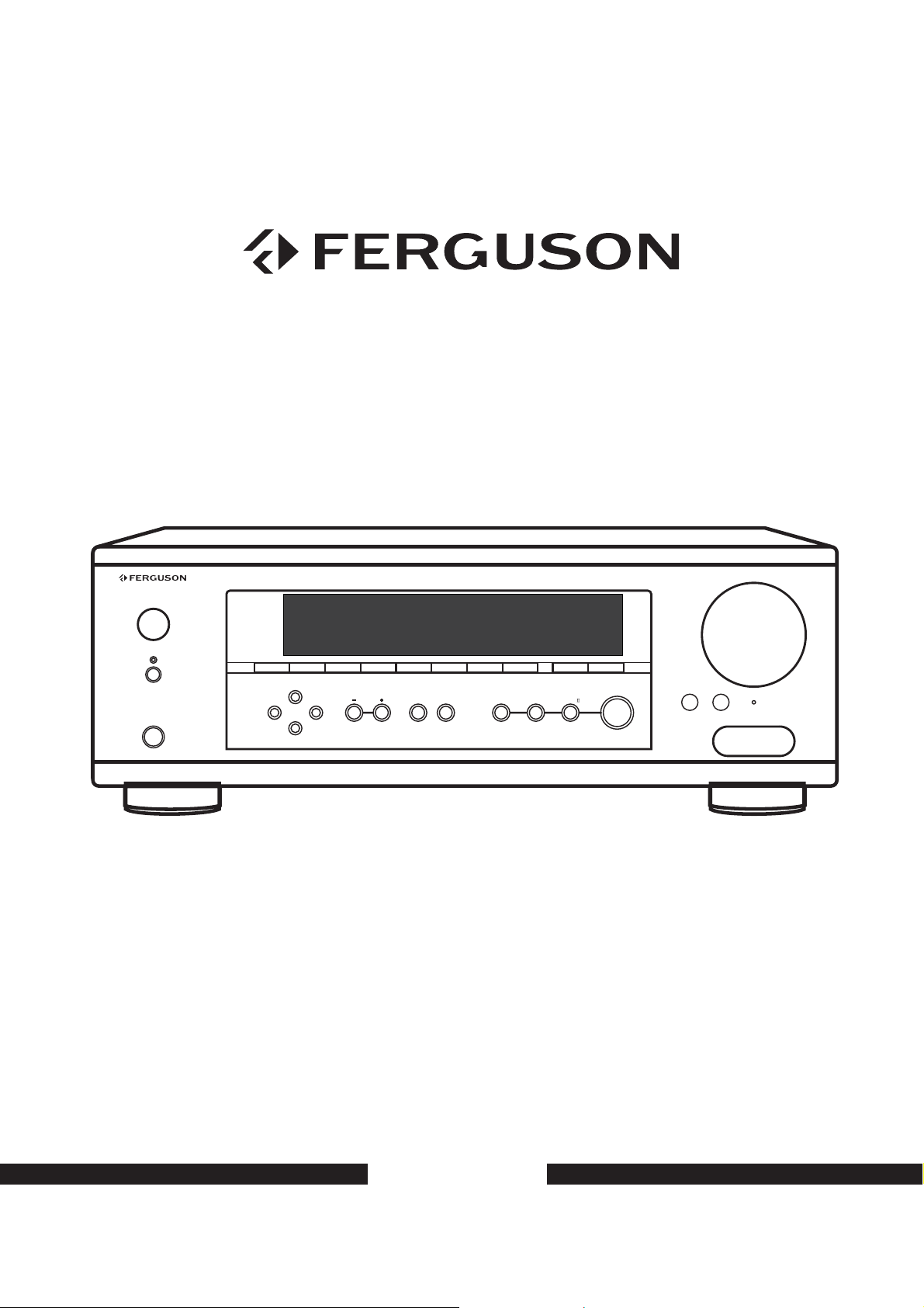
Operator's manual
POWER
STANDBY
PHONES
DOLBY DIGITAL/DTSRECEIVER AV-660
DVD
MEMORY
STATION
MASTER VOLUME
VIDEO1
VIDEO2
TUNING ST/MONO
BAND
APS
VIDEO3
TUNER
AUX DIREC T IN DISPL AY INPUT MODE
TAPE
SURROUND
BACK
DTS/
DOLBYDIGITAL STEREO
DOLBY PL x
SURROUNDMODE
BASS
VIDEO 3 INPUT
TREBLE
RESET
VIDEO AUDIOLR
AV-660
Page 2

CONTENTS
Important Safety Instruction………………………………………………………………………………………. 2-3
Before Use……………………………………………………………………………………………………………. .4
Connection………………………………………………………………………………………………………….. 5-9
Antenna Connection……………………………………………………………………………………………… 5
Standard speaker setup for surround sound……………………………………………………………………. 6
Speaker connection……………………………………………………………………………………………….. 7
DVD player, Television (Monitor), etc. connection…………………………………………………………….. 8
Remote control unit……………………………………………………………………………………….………… 9
Front panel information…………………………………………………………………………………………,…. 10
Remote control information………………………………………………………………………………………… 11-12
Rear panel information……………………………………………………………………………………………… 13
Basic operation………………………………………………………………………………………………………. 14
Radio operations……………………………………………………………………………………………………. 15
Radio data system…………………………………………………………………………….……………………… 16
Video operation……………………………………………………………………………………………………… 17
Delay time & dynamic range control………………………………………………………………………………. 18
Test tone, LFE trimmer & channel select………………………………………………………………………….. 19
Troubleshooting……………………………………………………………………………………………………… 20
Specifications………………………………………………………………………………………………………… 21
1
Page 3
IMPORTANT SAFETY INSTRUCTION
CAUTION: READ THIS BEFORE OPERATING YOUR UNIT.
1. READ AND FOLLOW INSTRUCTIONS---All the safety and operation instructions should be read before the
product is operated. Follow all operation instructions.
2. RETAIN INSTRUCTIONS---The safety and operation instructions should be retained for future reference.
3. HEED WARNINGS---Comply with all warnings on the product and in the operation instructions.
4. CLEANING---Unplug this product from the wall outlet before cleaning. Do not use liquid cleaners or aerosol
cleaners. Use a damp cloth for cleaning.
5. GROUNDING or POLARIZATION---This product may be equipped with a polarized alternating current line plug
(a plug having one blade wider than the other). This plug will fit into the power outlet only one way. This is a safety
feature. If you are unable to insert the plug fully into the outlet, try reversing the plug. If the plug should still fail to
fit, contact your electrician to replace your obsolete outlet. Do not defeat the safety purpose of the polarized plug.
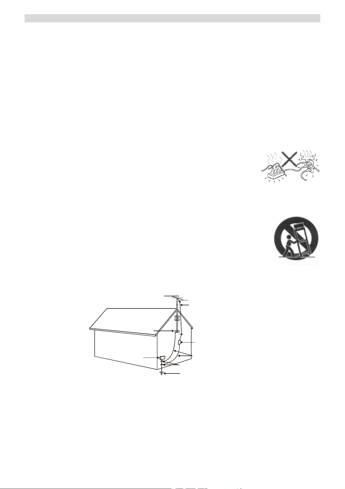
6. OVERLOADING---Do not overload wall outlets or extension cord as this can result in a
risk of fire or electric shock. Overloaded AC outlets, extension cords, frayed power cords,
damaged or cracked wire insulation, and broken plugs are dangerous. They may result in
a shock or fire hazard.
7. POWER SOURCES---This product should be operated only from the type of power source indicated on the
marking label. If you are not sure of the type of power supply to your home, consult your product dealer or local
Power Company. For products intended to operate from battery power, or other sources, refer to the operation
instructions.
8. ACCESSORIES---Do not place this product on an unstable surface or shelf. The product may
fall, causing serious injury to a child or adult as well as serious damage to the product. Any
mounting of the product should follow the manufacturer’s instructions and use a mounting
accessory recommended by the manufacturer. A product and cart combination should be
moved with care. Quick stops, excessive force, and uneven surfaces may cause the product and
cart combination to overturn.
9. OUTDOOR ANTENNA GROUNDING--- If an outside antenna or cable system is connected to the product, be
sure the antenna or cable system is grounded so as to provide some protection against voltage surges and built-up
static charges. The example below is for reference only. Correct grounding should always be installed by an
electrician.
ANTENNA
LEAD IN
WIRE
GROUND
CLAMP
ANTENNA
DISCHARGE UNIT
(NEC SECTION 810-21)
ELECTRIC
SERVICE
EQUIPMENT
GROUNDING CONDUCTORS
(NEC SECTION 810-21)
GROUND CLAMPS
POWER SERVICE GROUNDING
ELECTRODE SYSTEM
(NEC ART 250.PART H)
10. POWER-CORD PROTECTION---Power supply cord should be placed so that the power lead is not likely to be
walked on or pinched by items placed upon or against them, paying particular attention to cords at Wall plugs and
where the power lead exits from the product.
11. ATTACHMENTS---Do not use attachments not recommended by the product manufacturer as they may cause
harm to the unit.
2
Page 4
IMPORTANT SAFETY INSTRUCTION
12. CONTACT THE SERVICE DEPARTMENT SHOULD THE BELOW CONDITIONS EXIST—
a. When the power-supply cord or plug is damaged.
b. If liquid has been spilled, or objects have fallen into the product.
c. If the product has been exposed to rain or water.
d. If the product does not operate normally after following the operation instructions, adjust only those controls
that are covered by the operation instructions.
e. If the product has been dropped or damaged in any way.
f. When the product exhibits a distinct change in performance.
13. SERVICING---Do not attempt to service this product yourself as removing cover may expose you to dangerous
voltages or other hazards. Refer all servicing to qualified service personnel.
14. LIGHTNING---For added protection for this product during a thunderstorm, or when it is left unattended and
unused for long period of time, unplug it from the wall outlet and disconnect the antenna or cable system. This will
prevent damage to the product due to lightning and power line surges.
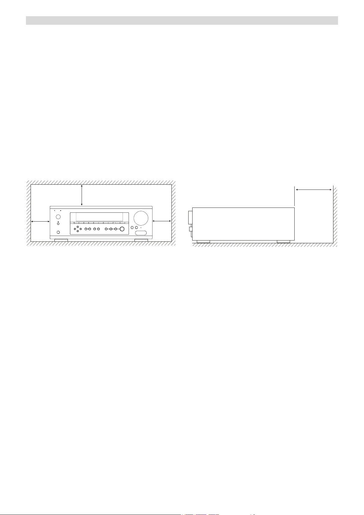
15. HEAT DISPERSION---Leave at least 10 cm of space between the top, back and sides of the unit and the wall or
other components for proper ventilation.
10cm or more
10cm or more
10cm or more
10cm or more
16. The apparatus shall not be exposed to dripping or splashing and that no objects filled with liquids, such as vases,
shall be placed on the apparatus.
17. NOTES ON USE
3
Page 5
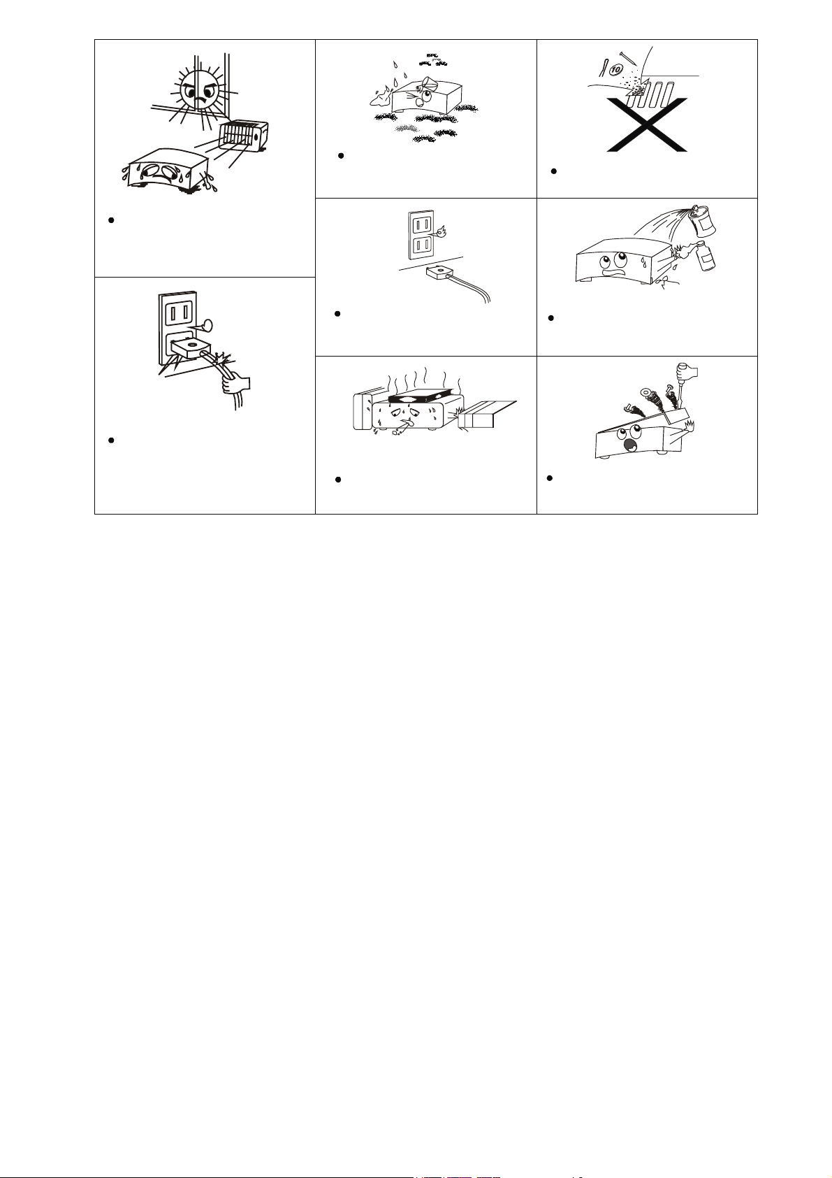
Avoid high temperatures
Allow for sufficient heat disper sion
when installed on a rack.
Keep the set free from moisture.
water,and dust.
Do not let foreign objects in the set.
Handle the power cord carefully.
Hold the plug when u nplugging the
cord.
Unplug the power cord when n ot
using the set for long periods of
time
*(For sets with ventilation holes)
Do not obstruct the ventilation
holes
Do not let insect icides,benz ene,a n d
thinner come in cont a ct with the set.
Never disassemble or modi fy the set
in any way.
4
Page 6
BEFORE USE
READ THIS BEFORE OPERATION
1. Choose the installation location of your unit carefully.
Avoid placing it in direct sunlight or close to a source
of heat. Also avoid locations subject to vibration and
excessive dust, cold or moisture.
2. The ventilation holes should not be covered. Make
sure there is enough space above and beside the
amplifier/receiver (about 4 inches). Do not place a
CD player or other equipment on top of the
amplifier/receiver.
3. Do not open the cabinet as this might result in
damage to the circuitry or electrical shock. If a
foreign object gets into the set, contact your dealer or
authorized service center.
4. When removing the power plug from the wall outlet,
always pull directly on the plug, never on the cord.
5. Do not attempt to clean the unit with chemical
solvents as this might damage the finish. Use a clean,
dry cloth.
6. Keep this manual in a safe place for future reference.
Back-up Memory Function
This is the function that preserves the preset memory and
most-recent memory function. In the event of a power
failure, or if the power cord of this unit is disconnected
from the electric outlet, the back-up memory will
preserve the preset memory and most-recent memory
functions for as long as approximately 1 week.
If the power supply is interrupted for 7 days or longer, the
memory settings will be erased.
When to use RESET switch
1. When this system is subjected to an electrical shock.
2. When the power is interrupted.
In this case, try the following:
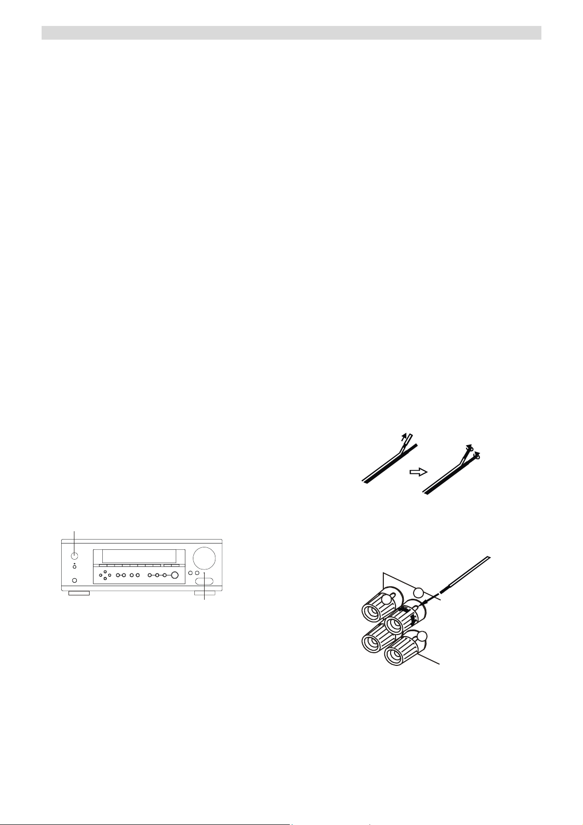
Switch on the POWER, use a paper clip to press the
RESET button for more than 3 seconds duration.
POWER ON/OFF
BEFORE CONNECTION
Caution
Turn off the power of all the equipment before making
connections.
Read instructions of each component you intend to
connect to this unit.
Be sure to insert each power plug securely. To
prevent hum and noise, do not bundle the
interconnection leads with power cord or speaker
leads.
Speaker Connections
Caution:
To avoid damaging the speakers with a sudden high-level
signal, be sure to switch the power off before connecting
the speakers.
Check the impedance of your speakers.
Connect speaker with an impedance of 8 ohms or
more. The amplifier’s red speaker terminals are the +
(positive) terminals and the black terminals are the –
(negative) terminals.
The + side of the speaker cable is marked to make it
distinguishable from the – side of the cable. Connect
this marked side to the red + terminals and the
unmarked side is the black terminal.
Prepare the speaker cords for connection by stripping
off approximately 10 mm or less (no more as this
could cause a short-circuit) of the outer insulation.
Twist the wires tightly together so that they are not
straggly.
How to connect
Red: positive (+)
Black: negative (-)
BAND
RESET
Note: If the RESET button is pressed for more than 3
seconds, all the current set up memory will be erased.
1
2
3
1. Unscrew the knob
2. Insert the speaker cable.
3. Tighten the knob and secure the cable.
5
Page 7
CONNECTION
A
A
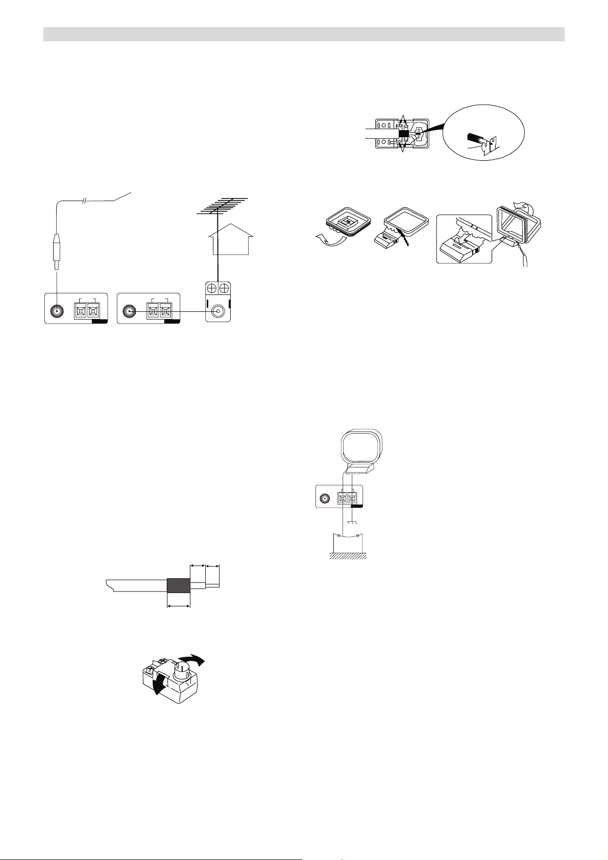
FM INDOOR ANTENNA
If you live reasonably close to a transmitter and want to
use the provided lead-type FM antenna, you will have to
connect it direct to the “FM 75Ω” socket.
Fit the metal sleeve of the lead-type antenna over the core
(center) pin of the (FM 75Ω) socket, extend the lead and
attach it to a window frame or wall with thumbtacks, or
move around the room, where reception is best.
Lead-type FM Antenna (75Ω provided)
Crimp the jagged metal fixtures so they hold the braided
portion using pliers, etc. Put the cover back in place.
Jagged metal
Insert into slit.
Jagged metal
AM INDOOR LOOP ANTENNA
To stand the antenna on a surface, fix the claw to the slot.
1
23
FM
75
AM
LOOP
Ω
ANTENA
FM
75
AM
LOOP
Ω
ANTENA
Optional
OUTDOOR FM ANTENNA (75Ω)
FM OUTDOOR ANTENNA
In an area where FM signals are weak, it will be
necessary to use a 75Ω unbalanced-type outdoor FM
antenna using the optional matching transformer, as
shown. Generally, a 3-element antenna will be sufficient:
if you live in an area where the FM signals are
particularly weak, it may be necessary to use one with 5
or more elements. Connect the coaxial cable of the
antenna to the matching transformer as shown. After
completing connection, plug the transformer into the “FM
75Ω” socket.
How to connect a coaxial cable to the matching
transformer
Strip the cable and dress it as shown.
①
7mm
4mm
3mm
Press both side tabs outward to remove the cover.
②
Wrap the core conductor around the central metal fixture
as shown.
High performance AM loop antenna provided with the
receiver is sufficient for good reception in most areas.
Connect the loop antenna’s wires to the AM antenna
terminals as shown.
Place the antenna on a shelf, for example, and move
around to obtain the best reception, place as far away as
possible from the entire system, speaker leads and the
power cords, to prevent unwanted noise.
AM Loop Antenna (provided)
M
FM
LOOP
75
Ω
NTENA
AM Outdoor
Anten na
AM Outdoor Antenna
If the AM loop antenna provided does not receive
sufficient reception, it may be necessary to use an outdoor
AM antenna.
Use an insulated cable of a length of 15 ft (5m) long, strip
one end, and connect this to the terminal as shown.
The antenna wire should be strung outdoors or indoors
near a window.
For better reception, connect the GND terminal to a
reliable ground.
Note: When connecting an outdoor AM antenna, do not
disconnect the AM loop antenna.
6
Page 8
CONNECTION
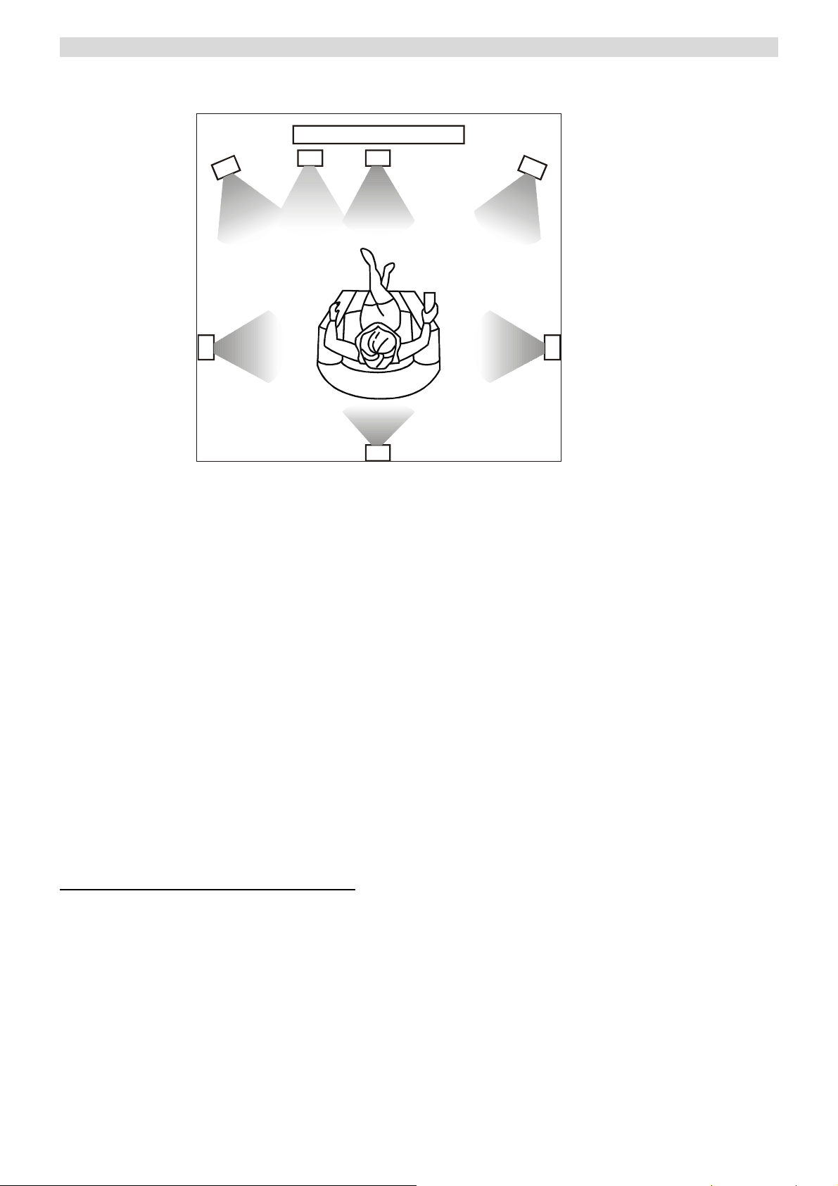
Standard speaker setup for surround sound
1
2
3
4
5
6
7
9
8
1. TV or Screen 2. Front Left Speaker 3. Subwoofer
4. Center Speaker 5. Front Right Speaker 6. Surround Left Speaker
7. Surround Right Speaker 8. Surround Back Speaker 9. Listening Position
Standard speaker setup for surround sound
● Front right and left speakers
These are the main speakers providing the front stereo effect of the sound image.
● Center speaker
Produces a rich sound image by serving as a sound source for the front right and left speakers and enhancing the
sonic movement.
● Surround right and left speakers
Adds three-dimensional sonic movement and produces environmental sound associated with the background and
effect sound for each scene.
● Surround back speaker
Required for enjoying Dolby Digital EX or DTS-ES audio.
Improves the quality of sound effects and the realistic acoustics.
● Subwoofer
Produces powerful and heavy bass.
Speaker placement
Ideal speaker placement varies depending on the size of your room and the wall coverings. Here, only typical examples
of speaker placement and recommendations are shown.
Important points regarding speaker placement
Front right and left speakers and center speaker
● Place these three speakers all at the same height.
● Place each speaker so that it is aimed at the location of the listener’s ears when at the listening position.
● Place front and right speakers at the same distance from the listening position.
Surround left and right speakers
Place these speakers so that their height is 3 feet (1 meter) higher than that of the listener’s ears.
Surround back speaker
Place this speaker so that its height is 3 feet (1 meter) higher than that of the listener’s ears.
Subwoofer
A subwoofer is recommended for the highest bass effect.
7
Page 9
CONNECTION
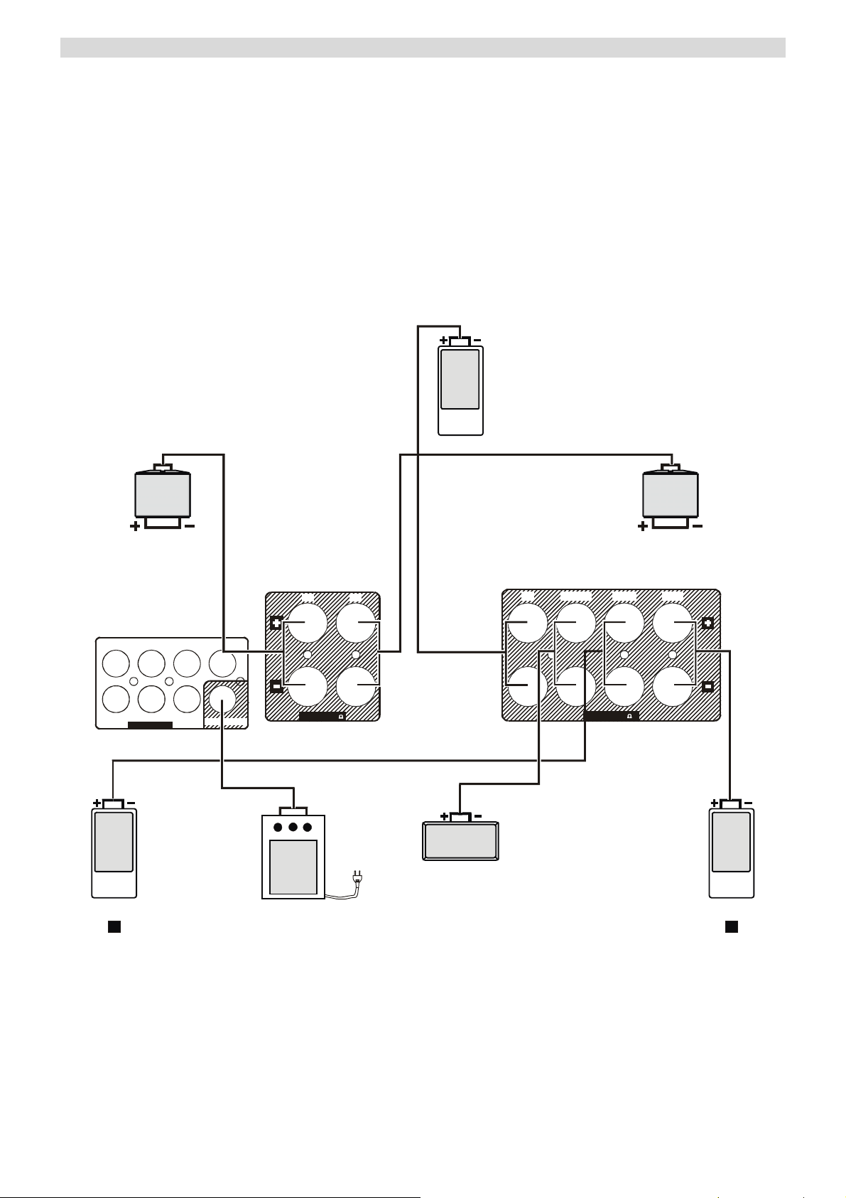
Connecting loudspeakers
To avoid damaging the speakers with a sudden high-level signal, be sure to switch the power off before connecting the
speakers.
Check the impedance of your speakers. Connect speaker with an impedance of 8 ohms or more.
The amplifier’s red speaker terminals are the + (positive) terminals and the black terminals are the – (negative) terminals.
The diagram below shows how loudspeakers are made.
Please note that all connections are made via loudspeaker cable except the subwoofer which is connected via a standard
phono cable.
BS
RS LS
L
RSBS CENTER LEFTRIGHT
SPEAKERS 8
FRONT
L
L
R
FRONT
R
LS
RSCSUB
6.1 DIRECT I N
BS
SUB LINE OUT
LSRS
SPEAKERS 8
CENTER
SUBWOOFER
8
Page 10

CONNECTION
Connecting video components
When connecting video components such as DVD
players, cable boxes, satellite receivers and television,
you can use different types of cables depending on how
the video component is equipped.
Video connections:
If the video component is equipped with S-VIDEO jacks,
it is recommended to connect to your Receiver or directly
to the television monitor using an S-VIDEO cable.
S-VIDEO cables provided better picture clarity and
resolution. If the video component is not equipped with
an S-VIDEO jack, use a conventional RCA or RCA
composite cable to connect to your Receiver or directly to
the television.
The illustration here shows how to connect video
components to your Receiver.
Note:
When connecting more than one video component to your
Receiver (i.e. VCR and DVD player) it is easier to use
either all S-VIDEO cables or all RCA to RCA composite
cables. This allows both video signals (DVD and VCR) to
be sent through your receiver to the TV monitor using
just one video input on the TV (S-Video or RCA).
Regardless of the video component being played DVD or
VCR, the picture will always appear on the same video
input of the monitor.
If you use both S-Video and RCA composite cables to
connect different video components to your Receiver, you
must also use both S-Video and RCA composite cables to
connect the TV monitor to your Receiver.
For example, if you connect a DVD player to your
Receiver using S-Video cable and a VCR using an RCA
to RCA composite cable, you must also connect the TV to
your Receiver using both types of cables. This requires an
S-Video cable from the S-Video monitor out jack on your
Receiver to an S-Video input on the TV (i.e. Video 1). In
addition, you must use an RCA composite cable from the
composite video monitor out jack on your Receiver to an
RCA composite video input on the TV but not the same
input used for the S-Video cable (i.e. Video 2). Using this
type of dual cable video connection, you will need to
switch the TV video input source from TV to Video 1 to
Video 2 depending on the video source being played-TV,
DVD or VCR.
Audio connections:
Some video components are equipped with special digital
audio outputs (i.e. DVD players). If your video
component is equipped with a digital audio output, it is
recommended that you connect to the your Receiver
using a digital cable. Digital audio cables are required to
use the DTS and Dolby Digital surround sound modes. If
you do not use digital connections, your Receiver will
only operate in Dolby PRO LOGICII, PASSTHRU,
MOVIE, MUSIC, ROOM, THEATER and HALL
surround modes.
There are two types of digital cables-coaxial (75 ohm)
and optical. This Receiver is equipped with both types of
digital inputs. These inputs are labeled COAXIAL IN and
OPTICAL IN on the rear of the unit. Connect the video
component outputs to any one of the two digital inputs on
your Receiver.
If the video component is not equipped with a digital
output, use a dual RCA to RCA composite audio cable to
connect to your Receiver.
Note:
When an optical cable is used, remove the protection caps
from the component and your Receiver before attempting
to insert the optical cable. If not using an optical cable or
if the cable is removed, always re-install the protection
caps to prevent dirt and dust from entering the inputs. If
using a coaxial digital cable, leave the protection caps in
both the video component and your Receiver.
9
Page 11
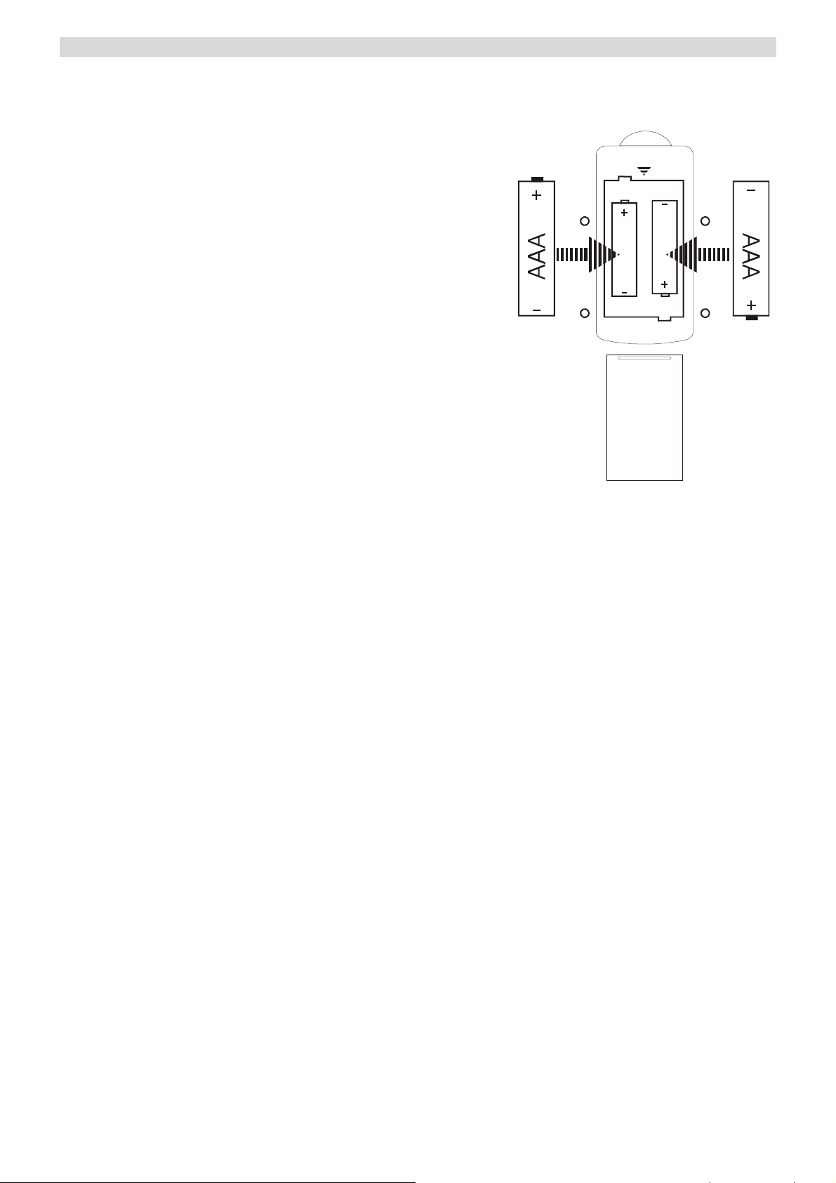
REMOTE CONTROL UNIT
By using the provided remote control unit, the receiver
can be controlled from your listening position.
To use the remote control unit, point it at the REMOTE
SENSOR window of the receiver.
Notes:
Even if the remote control unit is operated within the
effective range, remote control operation may not
work if there are any obstacles between the unit and
the remote control.
If the remote control unit is operated near other
products that generate infrared rays, or if other
remote control devices using infrared are used near
the unit, it may operate incorrectly.
To simplify explanation, this manual refers to names
of buttons and controls on the front panel, making no
mention of the use of remote control unit.
BATTERY INSTALLATION
● The power is turned on/off (standby) by pressing the
POWER button on the remote control unit in standby
mode.
Precautions concerning batteries
Be sure to insert the batteries with correct positive+
and negative – polarities.
Use batteries of the same type. Never use different
types of batteries together.
Do not heat or disassemble batteries and never
dispose of old batteries by throwing them in a fire.
1. Remove the battery compartment cover.
2. Insert two “AAA” dry batteries.
Make sure that the batteries are inserted with their
positive “+” and negative “-” poles positioned
correctly.
3. Close the cover until it clicks.
If the distance required between the remote control
unit and main unit decreases, the batteries are
exhausted. In this case, replace the batteries with
new ones.
10
Page 12
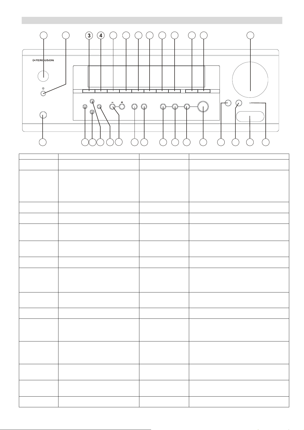
FRONT PANEL INFORMATION
1 2 5 6 7 8 9 10 11 12 25
MASTER VOLUME
TREBLE
VIDEO AUDIOLR
POWER
STANDBY
PHONES
DOLBY DIGITAL/DT S AV RECEIVER AV-660
DVD VIDEO 1 VIDEO 2 VIDEO 3 TUNER TAPE AUX DIR ECT IN DISPLAY INPUT MODE
STATION
MEMORY
APS
BAND
TUNING ST/MONO
SURROUND
BACK
DTS/
DOLBY DIGITAL STEREO
DOLBY PL Ⅱx
SURROUND MODE
BASS
VIDEO 3 INPUT
13 14 151617 18 19 20 21 22 23 24 26 27 2829
NO. & NAME DESCRIPTION NO. & NAME DESCRIPTION
1.
POWER
2.
STANDBY
3.
DVD
4.
VIDEO 1
5.
VIDEO 2
6.
VIDEO 3
7.
TUNER
8.
TAP E
Press this button to turn the unit into
standby mode or turn off the unit.
The power amplifier is in standby mode,
indicated by the stand by indicator.
Note: When this unit is in standby
mode, the Standby Lens is in Red
while in On mode, it is in Green.
Press this button to select DVD input.
Press this button to select Video 1 input.
Press this button to select Video 2 input.
Press this button to select Video 3 input.
Press this button to select TUNER.
Press this button to select tape deck.
16.
APS
17.
BAND
18.
TUNING +/-
19.
ST / MONO
20.
SURROUND BACK
21.
DTS/
DOLBY DIGITAL
22.
STEREO
23.
DOLBY PL II
Allocates and memorizes radio stations
automatically.
To alternate between FM and AM.
Tuner frequency up & down.
To alternate between Stereo and Mono mode when
listen to FM broadcast.
Push this button to turn on or off the surround back
output. And when surround back output is off, the
DTS NEO:6 is activated.
When play 5.1 CH source, and while you are
enjoying Stereo, press this button to playback
source in DTS/DOLBY DIGITAL.
With the unit in the STEREO mode, only front left
and front right speakers and Woofer are working.
When receiving Analog/digital PCM signal or 2CH
Pro Logic, turn on this button then the playing is
under analog 5.1CH state.
RESET
9.
AUX
10.
DIRECT IN
11.
DISPLAY
12.
INPUT MODE
13.
PHONES
14.
MEMORY
15.
STATION
Press this button to select AUX input.
Press this button to select the 6.1
analogue input.
Press this button to display the state of
input source. And when listening to the
FM broadcasting with RDS, press this
button to show PS, PTY, RT and RT.
To select input modes: ANA, OPT and
COAX when using digital in.
Jack for the stereo headphones.
To preset the broadcast stations.
To select a preset channel during the
tuner mode.
24.
SURROUND MODE
25.
MASTER VOLUME
26.
BASS
27.
TREBLE
28.
RESET
29.
VIDEO 3 INPUT
11
Selects surround modes: Theater, Hall, Passthru,
Movie, Music, and Room.
Rotate this knob clockwise or counterclockwise,
the master volume will be increased or decreased.
Press this button for Bass adjustment, then turn
Master Vo lu me to adjust the level. (Note: In
Prologic II, Surround and Digital 5.1 mode, no
function.)
Press this button for Tre ble adjustment, then turn
Master Vo lu me to adjust the level. (Note: In
Prologic II, Surround and Digital 5.1 mode, no
function.)
When this unit is ON, use a paper clip to press this
button for more than 3 seconds to reset the whole
system (including memories).
Input for VCR, Video Camera Recorder, etc. It
contains one video input and Analog Left and
Right inputs.
Page 13
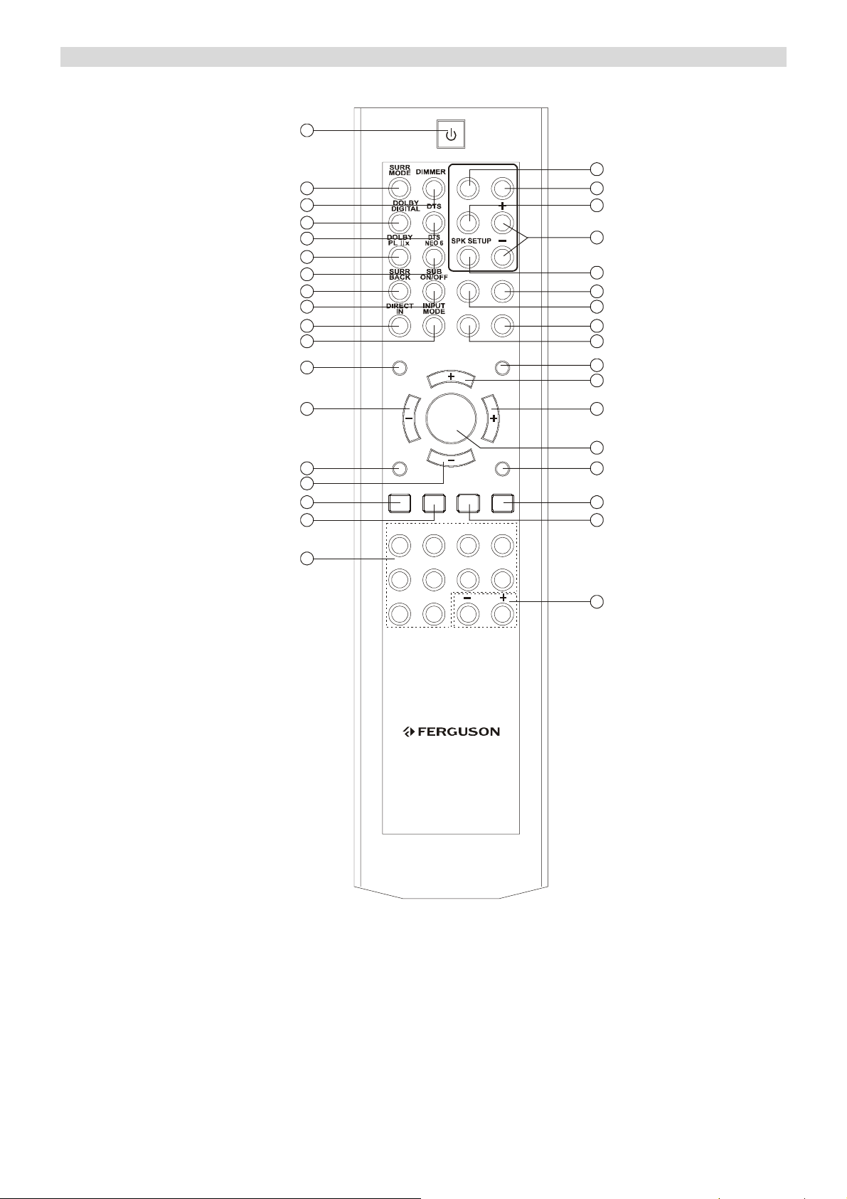
REMOTE CONTROL INFORMATION
V
A
1
10
11
12
13
14
15
16
17
18
BASS TREBLE
2
3
4
5
6
7
8
9
MUTE LFE TRIM
VOL
APS PTY
ST/MONO
1234
5
DELA Y
STEREO
DISPLAY
T. T ON E
DYNAMIC
SOURCE SEL
OL
CH
SELECT
SOURCE SEL
AUTO/
MANUAL
BAND
678
MEMORY
35
34
33
32
31
30
29
28
27
26
25
24
23
22
21
20
910+
TUNING
19
V-660
12
Page 14
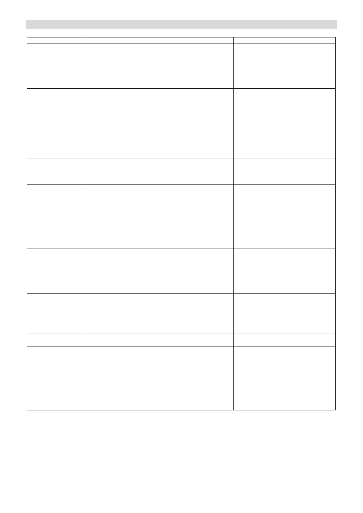
REMOTE CONTROL FUNCTION
NO. & NAME DESCRIPTION NO. & NAME DESCRIPTION
1.
POWER
ON/STANDBY
2.
SURR MODE
3.
DIMMER
4.
DOLBY DIGITAL
5.
DTS
6.
PRO LOGIC IIx
7.
DTS NEO: 6
8.
SURR BACK
9.
SUB ON/OFF
10.
DIRECT IN
11.
INPUT MODE
12.
MUTE
13/24.
VOL. +/-
14.
APS
15/25.
SOURCE SEL
16.
ST/MONO
17.
BAND
Press this button to turn this unit on or
Into standby mode.
Press this button to choose one of the
following surround modes: THEATER,
HALL, PASSTHRU, MOVIE, MUSIC
and ROOM.
Press this button to set the brightness of
the front display.
When play 5.1 CH source, and while you
are enjoying Stereo, press this button to
playback source in DOLBY DIGITAL.
When play 5.1 CH source, and while you
are enjoying Stereo, press this button to
playback source in DTS.
When receiving Analog/digital /PCM
signal or 2CH Pro Logic, turn on this
button then the playing is under analog
5.1CH state.
When the input signal is PCM, pressing
this button, you will get DTS NEO 6
MUSIC or DTS NEO 6 CINEMA.
Push this button to turn on or off the
surround back output. And when surround
back output is off, the DTS NEO:6 is
activated.
Press this button to turn on/off the output
of subwoofer.
Press this button to select the 6.1
analogue input.
To select input modes: ANA, OPT, and
COAX when using digital in.
Press this button to mute the sound, push
again to cancel the mute function.
Press these buttons to decrease or increase
the volume.
Allocates and memorizes radio stations
automatically.
Press this button to select source upward
or downward.
Press this button to alternate between
Stereo and Mono mode when listen to FM
broadcast.
Press this button to alternate between FM
and AM.
18.
NUMERIC
BUTTONS
19.
TUNING +/-
20.
AUTO /MANUAL
21.
MEMORY
22.
PTY
23.
CH SELECT
26.
LFE TRIM
27.
DYNAMIC
28.
TEST TONE
29.
DISPLAY
30.
STEREO
31.
SPK SETUP
32.
+ / -
33.
DELAY
34.
TREBLE
35.
BASS
These buttons are used to select a preset
channel during the tuner mode.
Tuner frequency up and down.
This button is used to select AUTO or
MANUAL tuning in AM and FM mode.
Press once to set to AUTO again for
MANUAL.
Press it to store the broadcast station as a
preset.
In FM state, press this button, the current
program type appears on the display, using
TUNING +/- to select the program type
you desire.
Select channels by pushing this button,
then use VOL. +/- buttons to balance
speakers.
Under the Pro Logic 5.1CH or DTS 5.1CH
mode, press this button and adjust the
volume to set the Low Frequency output
level
Press this button repeatedly to reach your
desired compression dynamic range.
To balance speakers in Dolby Digital or
Dolby Pro Logic mode.
Press this button to display the state of
input source. And when listening to the
FM broadcasting with RDS, press this
button to show PS, PTY, RT and RT.
With this unit in STEREO mode, only
Front Left & Front Right speakers and
Woofer have output.
Under PRO LOGIC II or Digital state, it
can change the desired Speaker Setting
shown on the display.
These buttons are used for SPK SETUP
and DELAY TIME, Treble and Bass
adjustment.
Press this button to set the delay time for
the Dolby digital/Dolby Pro Logic modes.
Press this button for Tre ble adjustment,
then press +/- key to adjust the level.
(Note: In Pro Logic II, Surround and
Digital 5.1 mode, no function.)
Press this button for Bass adjustment, then
press +/- key to adjust the level. (Note: In
Pro Logic II, Surround and Digital 5.1
mode, no function.)
13
Page 15
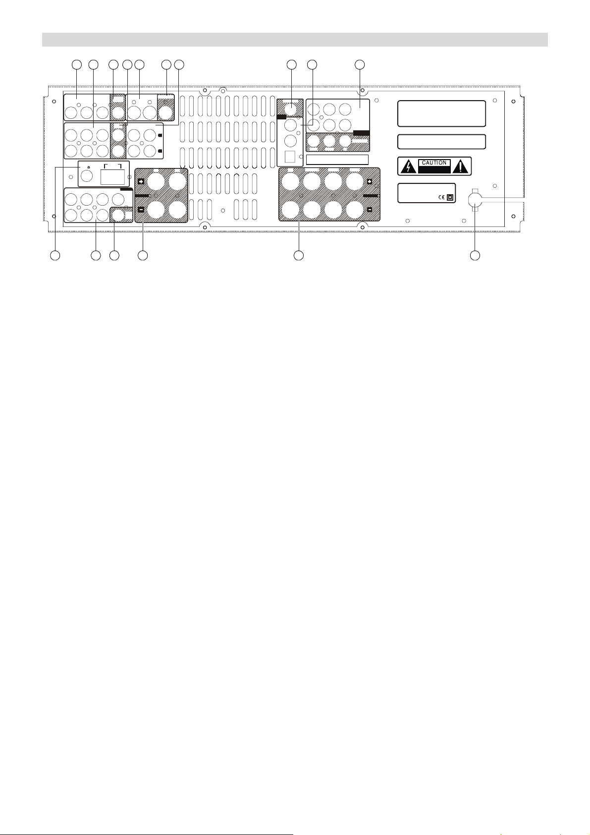
REAR PANEL INFORMATION
V
2 3 4 5 6 7 8 9 10
1
DVD-S IN VIDEO 1-S IN
TAPE
IN
SPEAKERS 8
VIDEO-S OUT
AUX
L
R
RS
LS
OUTCOAX.
DIGITAL
AUDIO
DVD COAX. IN
VIDEO 1 COAX. IN
SERIAL NO.
VIDEO 2 OPTICAL. IN
RSBS CENTER LEFTRIGHT
BB
P/C
RR
P/C
RR
P/C
RR
YP/C
DVD IN
Y
BB
P/C
VIDEO 1 IN
COMPONENT
VIDEO
IDEO OUT
Y
P/C
BB
SPEAKERS 8
Manufactured under license from Digital Theater Systems, Inc.
U.S. Pat. No s. 5,451,942, 5,956,674, 5,974,380, 5,978,762,
’
6,487,535 and other U.S . and world-wi de patent s issued and
pending. "DTS" are trademarks of Digital Theater Systems, Inc.
Copyright 1996,2003 Digital Theater Systems, Inc.
All Rights Reserved.
Manufactured under license from Dolby Laboratories .
"Dolby", "Pro Logi c" and the doub le-D
symbol are tra dem arks of Dolb y Labo rat ories .
POWER SOURCE:AC2 30-240V 50Hz
POWER CONSUMPTION :280W
," Su rround EX"
RISK OF ELECTRIC SHOCK
DO NOT OPEN
~
VIDEO 2
DVDINVIDEO 1
IN
DVD VI DEO 1 VI DEO 2
FM
75
LRLSRSC
VIDEO
IN
OUT
TAPE
OUT
AM
LOOP
6.1 DIR IN
BS
SUB
SUB
SUB
LINE
LINE
OUT
OUT
14141211
1413
1. VIDEO IN
- DVD IN: connect to the line output terminals of a DVD player.
- VIDEO 1 / VIDEO 2 IN: connect to the output terminals of a VCR to the VIDEO 1 and VIDEO 2 IN.
- AUDIO IN: connect to the output of external players.
2. AUDIO IN
- DVD: connect to the output of a DVD player
- VIDEO 1 / VIDEO 2: connect to the output of VCD players.
3. VIDEO OUT: connect TV set to the VIDEO OUT.
4. TAPE OUT: connect to the line input terminals on the TAPE DECK.
5. S-VIDEO INPUTS
- DVD-S IN: connect to the line output terminal of a DVD player.
- VIDEO-S IN: connect to the output terminal of a VCR to the VIDEO-S IN.
6. VIDEO-S OUT: connect TV set to the S-VIDEO OUT.
7. ANALOGUE AUDIO IN
- TAPE IN: connect to the line output terminals on the TAPE DECK.
- AUX: connect to the line output of an external player.
- PHONO: connect to the line output of a turntable.
DIGITAL AUDIO TERMINALS
8. COAXIAL OUT: digital audio output to the digital coaxial input of another amplifier, external recording device
or decoder.
9. DIGITAL IN terminals
- DVD COAXIAL IN: digital audio input to the digital output of a DVD player.
- VIDEO 1 IN: digital audio input to the digital output of a VCD player.
- VIDEO 2 IN: digital audio input to the digital output of a VCD player.
10. COMPONENT VIDEO terminals
11. FM / AM ANTENNA: connect to the 7 channels output terminals of another player.
12. 6.1 DIRECT IN: connect to the 7 channels output terminals of another amplifier.
13. SUB LINE OUT: connect to a active subwoofer. (refer to speaker connection diagram)
14. SPEAKERS 8Ω: connect to the external speakers.(refer to speaker connection diagram)
15. POWER CORD: connect to the A/C socket.
14
Page 16
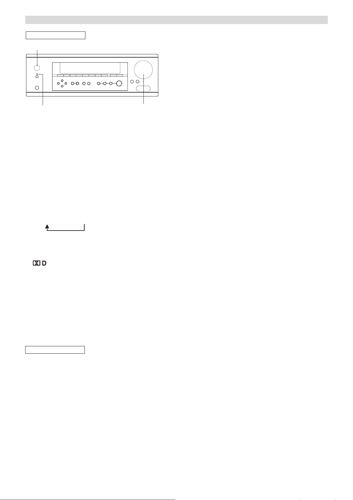
BASIC OPERATION
BASIC OPERATION 1
POWER
STANDBY
3
MASTER VOLUME
1. Press the POWER button to ON.
2. Press STANDBY button to switch on the unit.
3. Select the desired source by pushing the
corresponding button.
DVD (ANA, COAX)
VIDEO 1 (ANA, COAX.)
VIDEO 2 (ANA, OPT.)
VIDEO 3 (ANA)
TUNER (FREQUENCY)
TAPE
AUX
Note: INPUT MODE is used to select one of the 3
Modes.
ANA→OPT→COAX
When DVD, VIDEO 1, VIDEO 2 is selected, press the
INPUT MODE button and select “ANALOG”,
“OPTICAL” or “COAXIAL” in accordance with your
connection.
If
appears on the display:
A digital input source (OPT or COAX) has been
selected, and the source is connected successfully.
If “ UNLOCK” appeared for 5 seconds on the display:
The source is not connected properly or the source is
not switched on.
In that case, connect and switch the source on, or
select ANALOG by pressing the INPUT MODE button.
4. Play the source, and gradually turn up the volume to
the required level with the MASTER VOLUME
control.
BASIC OPERATION 2
A. POWER & STANDBY/ON button
Press this button to turn the power on/off.
The STANDBY indicator lights up in power standby
mode and goes out when this unit is turned on.
B. STEREO
With the unit in the STEREO mode, only Front Left and
Front Right Speaker and Woofer have output.
C. PRO LOGIC IIx
Dolby® Pro Logic® IIx technology (PLIIx) is an
extension of Dolby Pro Logic II (PLII) matrix-decoding
technology. Dolby Pro Logic IIx technology offers
decoders more flexibility in deriving additional outputs to
take better advantage of all the amplifiers and speakers
found in higher-end surround systems, and to do so from
a wider range of program material and sources.
There are two standard modes: Movie, Music.
How to get PL II x:
After power on this unit
1. Press the DOLBY PL IIx button on the front panel or
on the remote, you will get SURROUND BACK 1
SPEAKER DOLBY PL II x 6 MOVIE (factory default
mode), press one of these buttons again, you will get
SURROUND BACK 1 SPEAKER DOLBY PL II x 6
MUSIC;
2. Press the SURROUND BACK button on the front
panel or on the remote, you will get SURROUND
BACK OFF DOLBY PL II MUSIC (if the previous
mode is movie mode, you will get SURROUND BACK
OFF DOLBY PL II MOVIE), by this time, if you press
DOLBY PL IIx button, you will get SURROUND
BACK OFF DOLBY PL II MOVIE;
3. Press the SURROUND BACK button on the front
panel or on the remote, you will get SURROUND
BACK 1 SPEAKER DOLBY PL II x 6 MOVIE
MODE, by this time, if you press DOLBY PL IIx button,
you will get SURROUND BACK 1 SPEAKER
DOLBY PL II x MUSIC MODE.
Note: During the press, the corresponding wording
appears on the display.
D. SURROUND MODE
This mode is possible to achieve a realistic sound field
with a “three dimensional” feel, giving the sense of
distance, movement and relative position, and creating a
surprisingly real and powerful sense of presence when
playing movie software in AV rooms.
There are six surround modes: PASSTHRU, MOVIE,
MUSIC, ROOM, THEATER and HALL,
E. DIRECT IN
Press this button when you want to enjoy the 6 discrete
channels of high quality digital audio from DTS/AC3
program source.
F. RESET
When this unit is ON, use a paper clip to press this button
for more than 3 seconds to reset the whole system
(including memories).
G. PHONES jack
For private listening, insert optional (not included)
headphones (1/4-inch plug) into the PHONES jack, and
then the center and surround speaker will be cut
automatically. (Note: When the headphone is used, the
output will down mix to STEREO automatically.)
H. AV 3 IN
The input ports are for VCR, Video Camera Recorder, etc.
It contains one optical, one S-video, one video input port
and Analog Left and Right input ports.
I. Dolby Digital EX
When using surround back speakers, the Dolby Digital
source is played back using the matrix 6.1-channel
decoder.
J. DTS-ES Discrete 6.1
With the additional of the surround back channel, this
new format has all 6.1 channels recorded independently
for a completely discrete digital format. Since all
channels are recorded independently, high-fidelity
surround playback with the increased sound space is
achieved.
15
Page 17
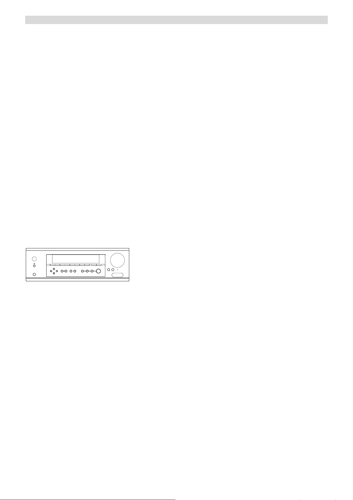
BASIC OPERATION
K. DTS-ES Matrix 6.1
This format has the surround back channel matrix
encoded and inserted into the left and right surround
channels so that at playback the output for the left, right,
and back surround channels are decoded using a
high-precision matrix decoder.
L. DTS Neo: 6
This mode is for 6.1-channel playback of sources such as
PCM or analog sources that have only two channels. The
outputs of all six channels are a wide frequency range
with a great separation between the different channels.
This mode can be set to the Cinema mode designed for
playing movies and the Music mode designed for
listening to music.
The Cinema mode is good for movies. The reproduced
surround sound provides the same realistic feel of
movement as 6.1-channel sources. This mode can be used
with VHS and television programs with stereo sound.
The music mode uses the surround channels to provide a
natural sound space that cannot be provided with normal
stereo output. This mode can be used with music CDs and
other stereo sources.
How to get DTS NEO:6
When the input signal is PCM, pressing DTS/DOLBY
DIGITAL button on the front panel or DTS NEO: 6
button on the remote, you will get DTS NEO 6 MUSIC or
DTS NEO 6 CINEMA.
Radio Operations
BAND
Automatic Tuning
1. Press the POWER button, then press the STANDBY
button to ON.
2. Push the TUNER button on front panel.
3. Select the FM or AM by pressing the BAND button
on front panel or remote control.
4. Press the “AUTO/MANUAL” button on the remote
control to activate automatic selection. (Default mode
is Manual selection)
Note: Auto appears on the display.
5. Press TUNING + and TUNING - to select the station
you want to listen to. When a station is tuned in, the
tuning process will stop automatically. (Automatic
selection)
6. Press TUNING + or TUNING - again to select
another channel.
Manual Tuning
It is for selecting stations, which cannot be tuned
automatically (manual selection)
To tune a channel manually:
Skip step 4 in the above procedures. Each time the
TUNING + or TUNING - button is pressed momentarily
(0.5 second or less), the frequency changes by a fixed
step. FM: 50 kHz steps; AM: 9 kHz steps
Two FM modes available:
Press ST/MONO button on front panel or remote control
to alternate between Stereo mode and Mono mode.
Stereo
8
FM stereo broadcasts are received in stereo and the “
”
indicator lights on the display.
Mono
To compensate for weak FM stereo reception, select this
mode. Reception will now be forced monaural, reducing
unwanted noise.
If DISPLAY button is pressed, the details of incoming
source will be displayed.
Preset Tuning
This facility is used to store FM, AM broadcasting from
channel 1 to20 respectively.
Automatic Memory Presetting
1. Push the TUNER button on front panel.
2. Select AM or FM by pressing the BAND button.
3. Press the “APS” button on front panel or remote
control.
Up to 20 of the best-received stations in your area
will be automatically stored.
How to select preset stations
Press the STATION button on the front panel or directly
press the numeric buttons on the remote to select a preset
channel during the tuner mode.
Manual Memory Presetting
1. Push TUNER button on front panel.
2. Select AM or FM by pressing the BAND button.
3. Press the TUNING + or TUNING - buttons to select
a frequency channel you want to preset.
4. Press the MEMORY button briefly.
5. While the “MEM” indicator is lit, press TUNING+
or TUNING - button to select a preset station. The
station number will be displayed on the screen.
6. Press the MEMORY button.
To store more stations, repeat steps 3 to 6.
16
Page 18

RADIO DATA SYSTEM
RADIO DATA SYSTEM (RDS)
RDS is a method for the transmission of additional
information from local Radio Stations. It can only
operated in FM mode. For example, name of the station
broadcasting, name of the program or the type of program
will be shown on the multi-function display.
It functions only when the local broadcasting stations
have the RDS transmission and the signal is strong
enough.
Press the “DISPLAY” on the front panel or the “RDS”
button on the remote, there are functions for PS, PTY, CT
and RT.
a) PS (Program Service Name)
Press “DISPLAY” on the front panel until “PS” appears.
The current station name will be shown.
Note: “NO PS” will be shown if the signal from local
radio station is not strong enough or no such service.
b) PTY (Program Type)
Press ”DISPLAY” on the front panel until “PTY”
appears. The current name type of the program will be
shown.
Note: “NO PTY” will be shown if the signal from local
radio station is not strong enough or no such service.
c) CT (Clock - Time)
Press “DISPLAY” on the front panel. Then
“WAITING CT” will appear.
The current time from Radio Station will be shown, e.g.
15:30
Note: The Clock - Time will be only transmitted from
local radio station once a minute, so you need to wait for
less than 1 minute to show the result.
Note: “NO CT” will be shown if the signal from local
radio station is not strong enough or no such service.
d) RT (Radiotext)
Press “DISPLAY” on the front panel until “RT” appears.
Some Text messages will be shown.
Note: “NO RT” will be shown if the signal from local
radio station is not strong enough or no such service.
PTY SEARCH (Program Type Search)
1. Press the “PTY SELECT” on remote control, “PTY
SELECT” will flash on the display.
2. Press TUNING + /- to choose the program type, for
example, NEWS, SPORT, …etc.
3. Press “PTY SEARCH” again once you choose the
program type.
4. When the type of program tuned in, it will stop
searching, otherwise, “NO FOUND” will appear.
APS (Auto Program Search)
1. Select your FM or AM band.
2. Press the “APS” on front panel, it will search the
available stations. The searched stations will be
memorized in the respective band memory up to
maximum 20 memories.
Note: Weak station may also be storied in memorizes, so
manual memory presetting may be needed in order to
have better receiving.
17
Page 19
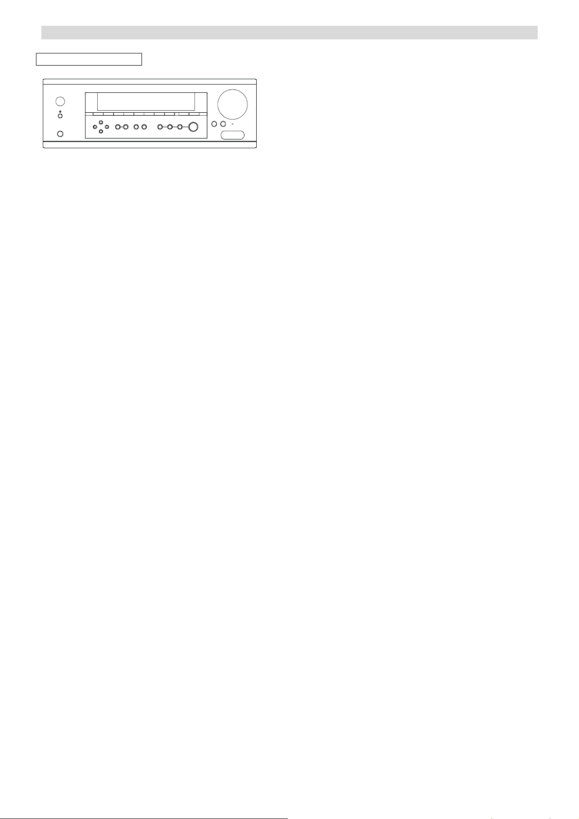
VIDEO OPERATIONS
Playing Video sources
BAND
1. Select the DVD, VIDEO 1, VIDEO 2 or VIDEO 3
modes by pushing the corresponding button on front
panel.
2. Play the component corresponding to the INPUT
selected.
3. The picture from the video source can be seen on the
TV and the sound from the video source will be
heard from the speakers.
18
Page 20
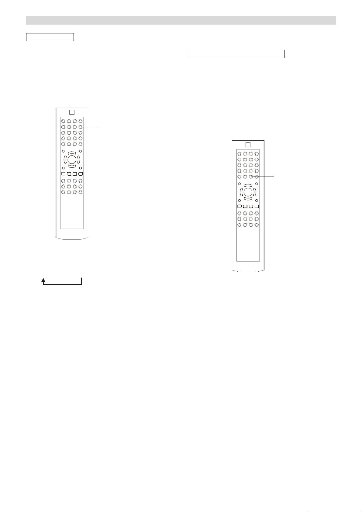
DELAY TIME & DYNAMIC RANGE CONTROL
DELAY TIME
The delay time can be individually set for the Dolby
Digital/Dolby Pro Logic II modes using the DELAY
(CENTER/REAR) buttons.
When you adjust the delay time in the Dolby Digital
mode, an additional 15 ms is automatically added to the
surround channels in the Dolby Pro Logic mode. The
current setting is shown on the display.
DELAY
DYNAMIC RANGE CONTROL
This button controls the compression range of sound track.
If the compression is large (DRC = 4/4), the sound effect
is retarded to a certain range. As a result, sound effect is
not as excited as normal range DRC = 0/4). It is useful
when you want to movies at the late night.
Press DYNAMIC on remote control repeatedly until
the desired compression range reached.
DYNAMIC
1. Press DELAY on the remote control as shown.
The corresponding speaker appears on the display.
i.e .C → S → BS
2. Press “+/-” button to set the time delay.
Delay Time Setting Adjustable Range
DOLBY DIGITAL MODES:
0-15 ms in 5 ms step (S-Delay)
0-5 ms in 1 ms step (C-Delay)
15-20 ms in 5 ms step (BS-Delay)
DOLBY PRO LOGIC II MODE:
10-25 ms in 5 ms step (S-Delay)
In the surround modes, the sound from the speakers
should be delayed slightly, relative to that from the front
speakers.
The optimum delay time will depend on acoustic
properties, whether the walls and furnishings reflect or
absorb sound, etc.
It is recommended that you try different delay times to
obtain the best effect. The delay is digitally synthesized.
For the highest sound quality with minimum noise and
distortion, the delay time can be set independently for
each surround mode using the DELAY TIME buttons,
with the current setting shown in the display.
DRC=0/4 No Compression
DRC=1/4
DRC=2/4
DRC=3/4
DRC=4/4 Greatest Compression
Note:
The Dynamic Range Control state will resume to normal
if you do not press it after 5 seconds.
Dynamic Range Compression is not possible with DTS
sources.
19
Page 21
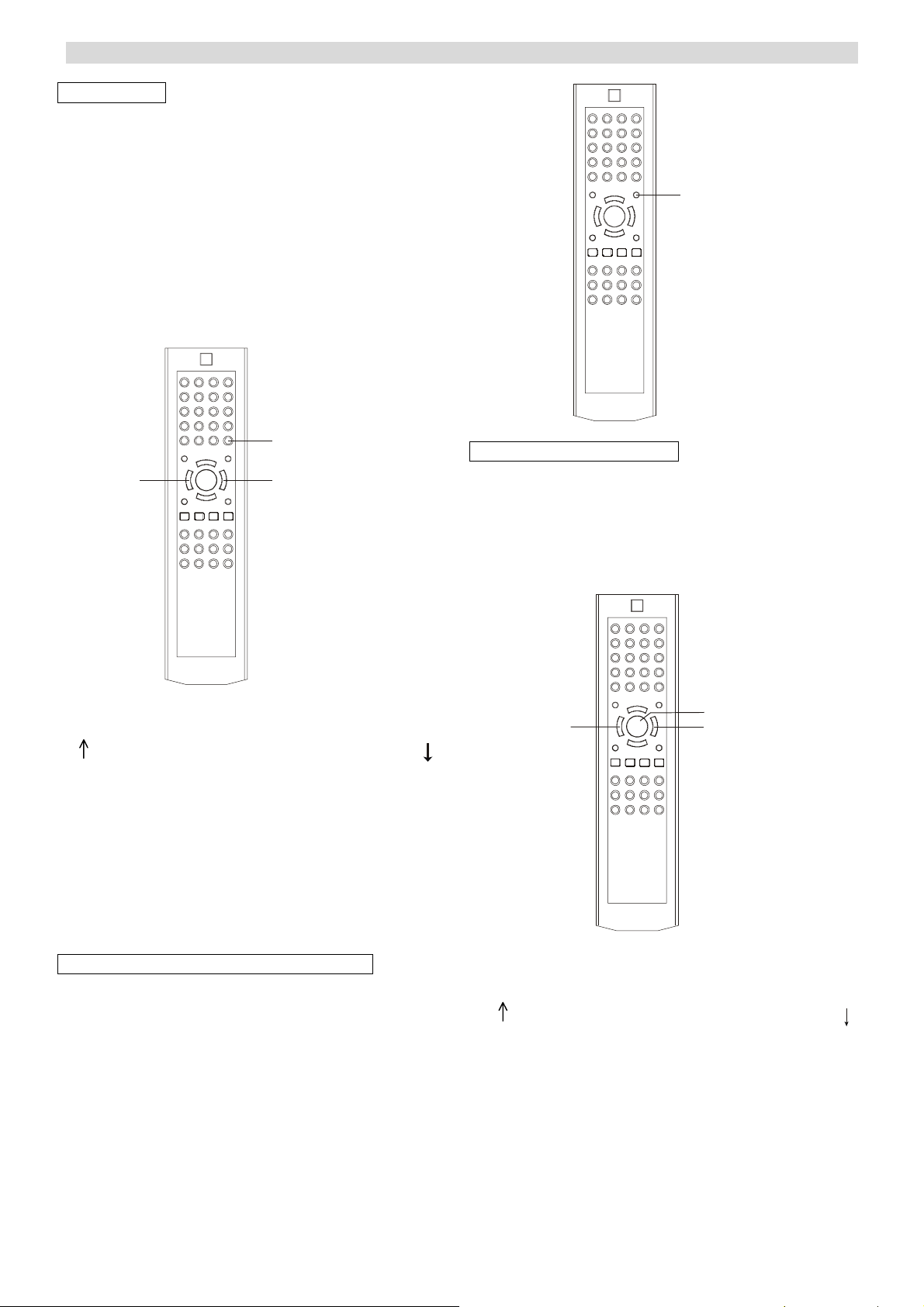
TEST TONE, LFE TRIMMER AND CHANNEL SELECT.
TEST TONE
Speaker Level balance Adjustment
The test tone function is useful to adjust the relative
volume between speakers in DOLBY DIGITAL or
DOLBY PRO LOGIC II mode.
Once the balance is set, you don’t have to change the
balance as long as the speakers aren’t moved.
1. Adjust the VOL. +/- to the normal listening level.
(Half of max. Volume is recommended)
2. Press the T.TONE button (on the remote control) in
DTS, Dolby Digital or Dolby PRO LOGIC II mode.
The test tone is emitted from each speaker each time you
press “T.TONE”.
LFE TRIM
T.T ON E
VOL
VOL
→ L(FRONT LEFT)→R (FRONT RIGHT)→LS (SUR. LEFT) →
← BS ← SUB ← C (CENTER) ← RS (SUR.R)
3. Select a speaker by pressing the “T. TONE” button
and adjust the level by pressing the VOL. +/- button.
The level of each speaker can be adjusted in 1 dB step
from –10 dB to +10 dB.
4. When the setting is finished, press the TEST TONE
button to stop the test tone.
Note: You must keep press T. TONE until one complete
cycle is finished.
LOW FREQUENCY EFFECT (LFE MIX)
LFE (LOW FREQUENCY EFFECT) MIX LEVEL
(LFE MIX)
Under COAX./OPT mode, when playing , input AC3 or
DTS 5.1CH signal, LFE will appear on the VFD, then
press LFE key on the remote, and again press VOL +/key to adjust the level between 0dB to –10dB.
Note: The LFE adjust state resume to normal, if
MASTER VOLUME is not press after 5 seconds.
CHANNEL SELECT
Balancing volume between speakers in 6.1 channel
mode when using the 6.1 analogue inputs.
As the Dolby Digital signal is decoded in the external
source, sometimes, you may have to balance volume
between speakers due to the location of speakers. In this
case:
CH
VOL
SELECT
VOL
1. Press “CH SELECT” on the remote, the following
loop will appear on the display:
→ L(FRONT LEFT)→R (FRONT RIGHT)→LS (SUR. LEFT) →
← BS ← SUB ← C (CENTER) ← RS (SUR. R)
2. Adjust the VOL.+/- to balance all speakers.
The level of each speaker can be adjusted in 1 dB
steps from –10 dB to +10 dB.
Note: If the Master Volume is not adjusted for 5 seconds
in Channel Trimmer state, it returns to normal state.
20
Page 22
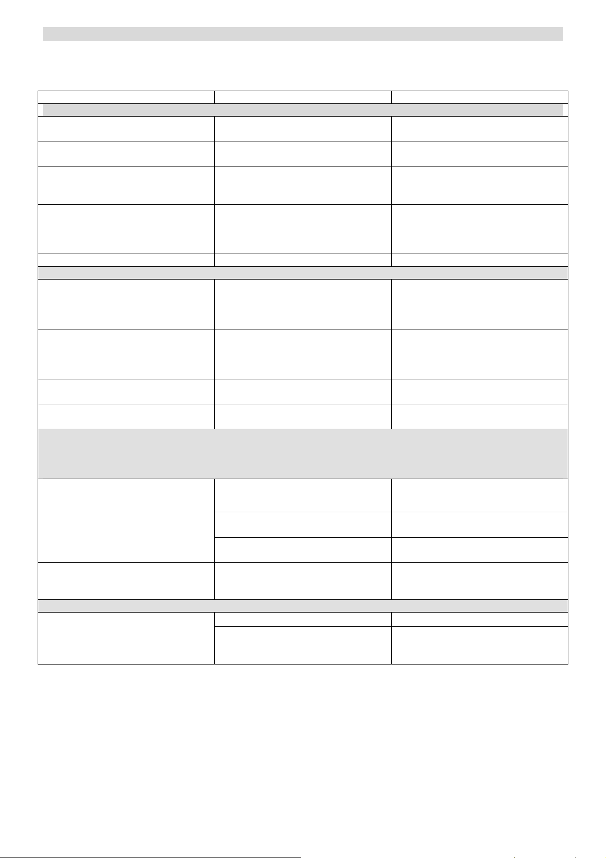
TROUBLESHOOTING
To determine any problem with your receiver, always check the most obvious possible causes first. If any problem still
remains after your having checked the items below, consult your nearest dealer.
Problem Probable Cause Suggestion
Amplifier
When listening to the music in stereo.
Left/right speakers reversed.
Low hum or buzz sound Power cords or lighting placed near
Sound is only heard from one channel One of the input cords is
Sound cuts off when listening to the
music or no sound even though power
is ON.
Low bass response. Speaker polarity (+/-) is reversed. Check all speakers for correct polarity.
Tuner
An unusual hissing noise is heard
when listening to the broadcast in
stereo, but not heard when listening
monaurally.
Noise is excessive in both stereo and
monaural broadcasts.
Sound is distorted and/or the volume
level becomes low.
Excessive distortion in speaker output Poor reception area Try using an antenna with more
Surround Effects: (Important) The center and rear speaker only operate with the unit is set to a Surround Sound
mode and the source material being played is recorded or broadcast in Dolby Digital, DTS or Dolby Pro Logic
surround sound. Stereo broadcasts or recordings will produce some rear channel effects when played in a
surround mode. However, mono sources will not produce and sound from the rear speakers.
No sound from the rear speakers
Speakers are connected wrong. After checking, if needed, reconnect.
Place this product as far as possible
this product.
disconnected. The BALANCE control
is set to one side.
Speaker impedance is less than
prescribed for this unit.
A slight noise may be heard because
the method used for modulation of
FM stereo broadcasts in different than
that used for monaural broadcasts.
Poor location and/or direction of the
antenna. Transmitted station is too far
away.
Broadcast signals are poor or poor
antenna placement
SURROUND ON/OFF button is set to
OFF.
from lighting or power leads
Connect the input leads and
adjust the BALANCE control.
After turning off the power and then
turning it on again, reduce the volume
or change to the correct 8 ohm
speakers.
Try reducing the treble sound by
turning the treble controls.
Set the FM mode to monaural by
pressing the STEREO/MONO button.
(Note that the broadcast will then be
heard as monaural sound)
If an indoor antenna is being used,
change to an outdoor antenna
elements.
Set the button to the desired surround
mode position
Source being played is not recorded or
broadcast in surround sound or stereo.
Cable not connected securely Check all rear speaker wires for good
No sound from the center speaker SURROUND mode button is not set
to DOLBY DIGITAL, DTS or
DOLBY PRO LOGIC II.
Remote Control Unit
The batteries are exhausted. Replace with new batteries. Remote control not working
The remote control unit is too far from
the receiver or out of the effective
range.
Use surround or stereo source
connection
Set the button to DOLBY DIGITAL,
DTS or DOLBY PRO LOGIC II.
Operate the Remote Control unit
within the effective range
21
Page 23

SPECIFICATIONS
AUDIO SECTION
Audio Power Output FRONT (L/R) 100W RMS x 2 (8 ohm, 1% THD)
CENTER 100W RMS (8 ohm, 1% THD)
SURR. (L/R) 100W RMS x 2 (8 ohm, 1% THD)
SURR. BACK 100W RMS (8 ohm, 1% THD)
Output Impedance FRONT (L/R) 8 ohm
CENTER 8 ohm
SURR. (L/R) 8 ohm
SURR. BACK 8 ohm
Total Harmonic Distortion Less than 0.05%
LINE INPUT
Input Sensitivity/Impedance 150mV/47kΩ
Frequency Response 20Hz~25KHz +0.5/-1dB
Tone Control Range BASS ± 6dB
TREBLE ± 6dB
Signal-Noise Ratio 75dB
WOOFER OUTPUT
Rated Output/Impedance 150mV/10kΩ
Frequency Response 10Hz~300Hz +3dB
FM TUNER SECTION
Frequency Range 87.5~108MHz
Sensitivity 14dB (5uV)
Antenna Terminal 75 ohm (unbalanced)
TUNER SECTION
Frequency Range 522~1629kHz, 9kHz step
Sensitivity 68 dB/M
Signal-to-Noise Range 30 dB
Antenna Loop Antenna
VIDEO SECTION
Standard Video Jacks
Input and Output 1 Vpp/75Ω
Level/Impedance
S-VIDEO SECTION
Standard S-Video Jacks
Output Level/Impedance CA 0.3 Vpp/75Ω
YA 1 Vpp/75Ω
GENERAL
Power Requirement AC230-240V~50Hz
Max Power Consumption 280Watts
DIMENSIONS 350 (W) x 430 (D) x 150 (H) mm
WEIGHT 11kg
*Design and specifications are subject to change without notice.
22
 Loading...