

Page 1
N069/R12 (05.03.15)
PANEL MR .
MRAMOROVÉ/GRANITOVÉ PANELY CZ
MARBLE/GRANITE PANELS GB
MARMORPLATTEN/GRANITPLATTEN D
Návod k montáži a použití
Instructions for installation and use
Bedienungsanleitung
Page 2

Důležitá upozornění
• Jakékoliv zásahy do panelu smí provádět pouze kvalifikovaná osoba. Před zahájením ta-
kové práce musí být panel vypnut od zdroje proudu. Jelikož se jedná o přírodní materiál,
který je křehký, je nutné dbát zvýšené opatrnosti při přepravě, manipulaci a montáži.
• Mramorovou desku panelu je možné ošetřovat jen prostředky, které nepoškodí kvalitu
povrchu (lesk).
• Před prvním zapnutím musí být teplota panelu vyrovnaná s teplotou v místnosti
(minimálně však +3°C).
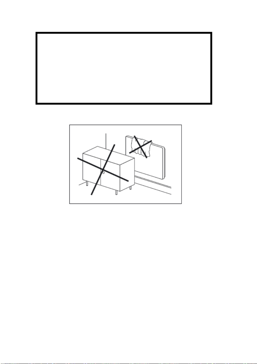
• V žádném případě panel nezakrývejte. Nápis „NEZAKRÝVAT“ upozorňuje, že jakýkoliv
materiál, kterým je zakryt panel může způsobit požár. Před panel se nesmí stavět žádný
nábytek ani věšet záclony (viz. obr. 7) a musí být zaručena volná cirkulace vzduchu.
• Pravidelně, minimálně pokaždé před zahájením topné sezóny odstraňujte prach z panelu.
Nedotýkejte se panelu z vany nebo sprchy!
• Toto topidlo není vybaveno zařízením pro kontrolu teploty místnosti. Nepoužívejte toto
topidlo v malých místnostech, jsou-li obsazeny osobami, které nejsou schopny opustit tuto
místnost vlastními silami, není-li zajištěn trvalý dozor.
• Tento spotřebič mohou používat děti ve věku 8 let a starší, a osoby se sníženými fyzický-
mi, smyslovými nebo mentálními schopnostmi nebo nedostatkem zkušeností a znalostí,
pokud jsou pod dozorem nebo byli poučeni o používání spotřebiče bezpečným způsobem
a rozumí případným nebezpečím.
• Děti si se spotřebičem nesmějí hrát. Čištění a údržbu vykonávanou uživatelem nesmí vy-
konávat děti bez dozoru. Dětem mladším 3 let by měl být zamezen přístup ke spotřebiči,
pokud nejsou trvale pod dozorem.
Děti ve věku od 3 do 8 let musí tento spotřebič zapínat/vypínat pouze za předpokladu, že
•
byl umístěn nebo nainstalován ve své zamýšlené normální provozní poloze, a pokud jsou
pod dozorem nebo byly poučeny o používání spotřebiče bezpečným způsobem a rozumí
případným nebezpečím. Děti ve věku od 3 do 8 let nesmějí zasouvat vidlici do zásuvky,
regulovat a čistit spotřebič nebo vykonávat údržbu prováděnou uživatelem.
Upozornění: Některé části tohoto výrobku se mohou stát velmi horkými a způsobit popále-
ní. Zvláštní pozornost musí být věnována přítomnosti dětí a hendikepovaných
lidí.
2
Page 3
POZOR!
Aby se zamezilo popraskání mramorové desky vlivem rychlého náběhu teploty,
je nutno při prvním uvedení do provozu dodržet tento časový náběhový cyklus:
20 minut ZAPNUTO
30 minut VYPNUTO
30 minut ZAPNUTO
30 minut VYPNUTO
Teprve po dokončení tohoto cyklu je možno panel provozovat v normálním
teplotním režimu.
obr. 7
3
Page 4
Návod k montáži a použití
Montážní návod
Instalace, elektrické připojení a první uvedení do provozu smí provádět
pracovník s odpovídající kvalifikací (dle vyhl. 50/78 Sb.).
Odstupy
Odstup spodní hrany spotřebiče od podlahy nesmí být menší než 50 mm.
Odstup na stranu, např. k nábytku, musí být minimálně 100 mm a smě-
rem nahoru minimálně 100 mm (viz. obr. 2).
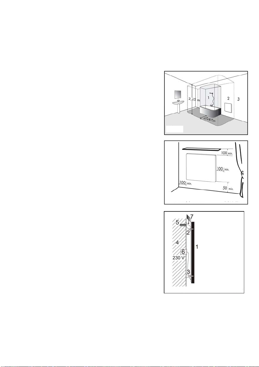
V koupelnách musí být panel instalován ve shodě s ČSN 33 2000-7-701
a smí být umístěn v souladu s obr. 1 v zónách 2 a 3.
Panel je zařízení třídy II a je chráněn proti stříkající vodě, krytí IP 44.
Panel nesmí být umístěn přímo pod zásuvkou elektrického proudu.
El. instalaci je nutné vybavit 2 pólovým vypínáním, u něhož se vzdálenost
rozpojených kontaktů rovná min. 3 mm.
obr.1
Rozměry jsou v mm
obr.2
1. Mramorový panel
2. Konzoly
3. Stavěcí opěrky
4. Stěna
5. Hmoždinky s vruty
6. Připojovací krabice
7. Krytka konzol
4
obr.3
Page 5
Montáž
Panel je zabalen samostatně v kartonové krabici a k uchycení na stěnu slouží
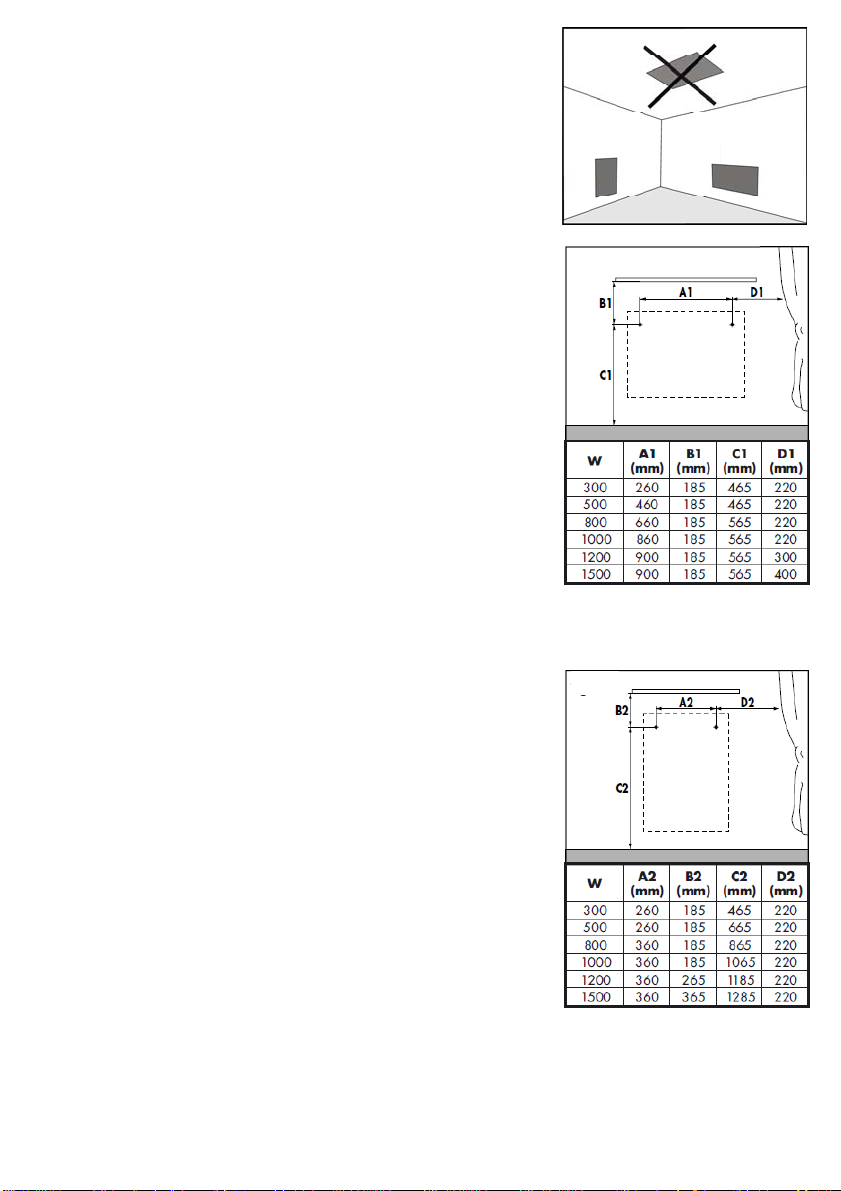
upevňovací konzoly.Panel lze na stěnu instalovat na délku nebo šířku, stropní
montáž je zakázána (obr. 4). Otvory pro konzoly vyvrtejte dle obr. 5 (instalace
na délku panelu) nebo dle obr. 6 (instalace na šířku panelu). Rozměry A jsou
rozteče vrtaných otvorů a rozměry B, C a D jsou minimální vzdálenosti otvorů od
okolních předmětů.
Konzoly upevněte ke stěně vruty do hmoždinek (nejsou součástí výrobku), tyto
je nutno volit s ohledem na druh materiálu stěny a na vyšší hmotnost panelu.
Panel zavěste na konzoly vždy za horní dva šrouby (dle způsobu zavěšení) a ke
konzole pevně utáhněte připravenými maticemi s podložkou. Upevňovací matice
jsou našroubovány na dvou šroubech panelu připraveny pro zavěšení naležato.
K panelu jsou přibaleny kromě upevňovacích konzol také stavěcí opěrky, kterými
se po našroubování na spodní šrouby panelu vymezí odstupová vzdálenost
panelu od stěny a krytky upevňovacích konzol.
Na obr. 3 je zobrazen boční pohled na panel po zavěšení na st
ěnu.
Elektrická instalace
Panel je vybaven dvoužilovým kabelem na 1/N 230 V / 50 Hz.
Barevné značení vodičů:
Fáze –
Střední (pracovní) vodič –
Přívodní vodiče mohou být opatřeny vidlicí (exportní trhy), odstranění vidlice
a zkrácení přívodního vodiče není důvodem pro ztrátu záruky
Napájecí kabel je připojený do krabice na stěně, viz. obr. 3. Jestliže je napájecí
přívod spotřebiče poškozen, musí být nahrazen výrobcem nebo jeho servisním
technikem nebo podobně kvalifikovanou osobou, aby se tak zabránilo vzniku
nebezpečné situace.
hnědý
,
modrý
.
Ovládání panelu
Doporučujeme zajistit ovládání panelu externím prostorovým termostatem s
vypínačem.
Prostorový termostat udržuje nastavenou teplotu vzduchu v místnosti.
Panel je dále vybaven omezovacím termostatem, který zajišuje, že maximální
teplota panelu nepřekročí 110 °C.
obr. 4
obr.5
obr.6
Demontáž panelu
Před uvolněním upevňovacích konzol odpojíme pomocí dvoupólového vypínače panel od sítě. S použitím nářadí uvolněte
montážní šrouby a panel nadzvedněte svisle nahoru tak, aby se konzoly uvolnily ze šroubů. Dále je nutné odpojit napájecí
kabel z krabice na zdi.
5
Page 6
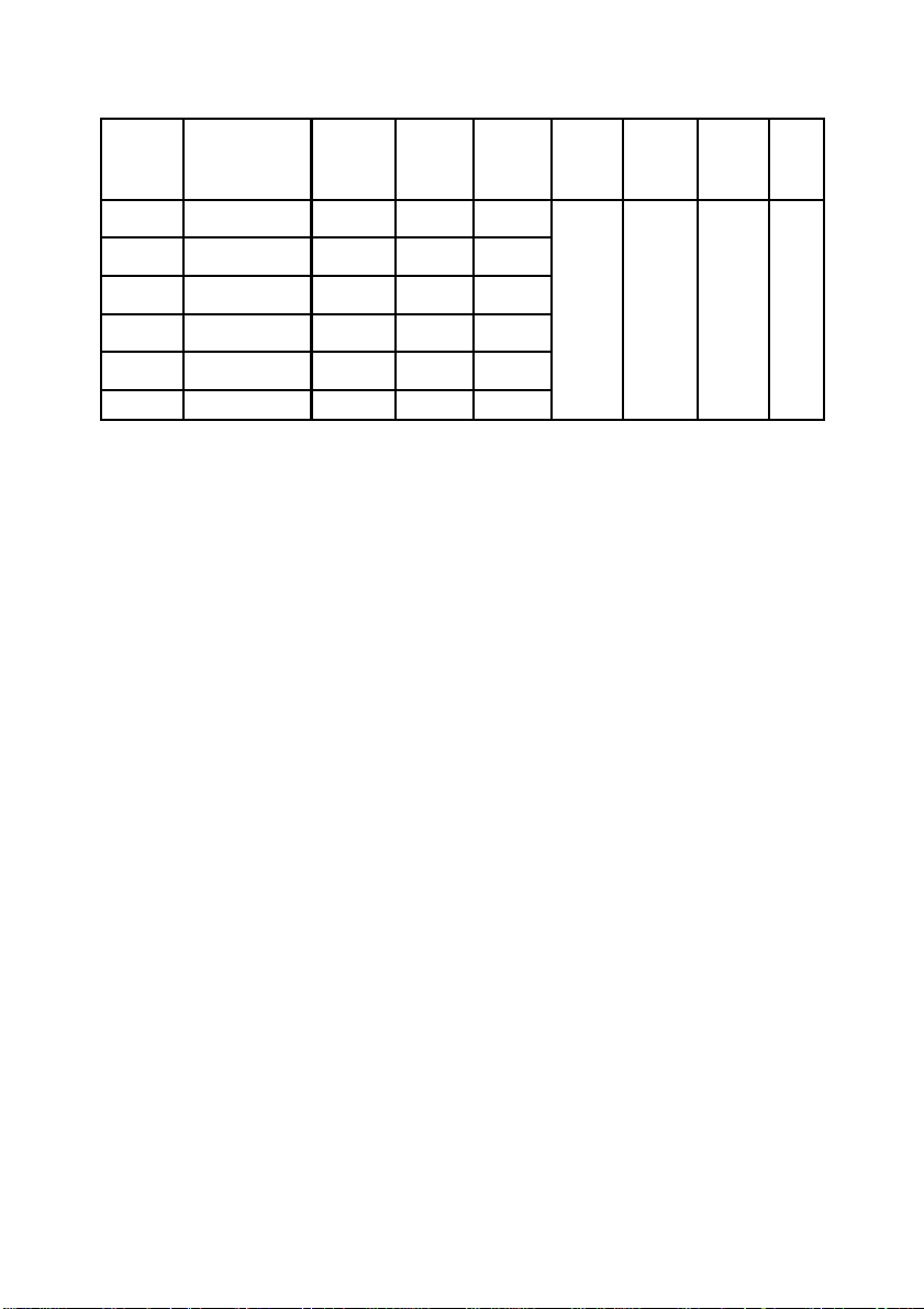
Technické údaje
TYP
MR 300 500x500x30 20 300 1,30
MR 500 700x500x30 28 500 2,17
MR 800 900x600x30 43 800 3,48
MR 1000 1100x600x30 53 1000 4,35
MR 1200 1300x600x30 62 1200 5,20
MR 1500 1500x600x30 72 1500 6,50
Rozměr (mm)
DxŠxH
Hmotnost
(kg)
Výkon
(W)
Panel je možné montovat na podklady třídy hořlavosti C, D.
Proud
(A)
Napětí Třída
230 V
AC
II 110 °C
Max.
povrch.
teplota
Krytí
IP 44
6
Page 7

Záruční podmínky
Dodavatel poskytuje na výrobky záruku 24 měsíců od data prodeje.
Záruka se nevztahuje na vady způsobené dopravou, nedbalou manipulací a neodbornou montáží. Záruka se rovněž nevztahuje na neodborný zásah do panelu a na běžné opotřebení výrobku.
Potvrzení o prodeji:.................................................................................................................
Datum prodeje:...................................................Výrobní číslo:........................................
Prodejce:.............................................................................
7
Page 8

Important Safety Instructions
• Only a qualified person is allowed to work on the panel. The panel must be disconnected
from the power supply before starting any work. Because the natural marble is a material,
it is necessary to be careful during transport, manipulation and montage. The marble slab
may only be cleaned with detergents which will not impair the surface quality (polish).
• Before switching on the panel for the first time its temperature must be the same as the
temperature in the room where it is to be installed (and at a minimum of +3°C above
zero).
• Do not cover your heating unit in any way. The "DO NOT COVER" warning tag is there to
remind you that any material covering the unit can catch fire. Never place or hang any
furniture or curtains in front of the panel (see Fig. 7) and ensure free air circulation.
• Regularly, at least each time before starting a heating season, clean the panel from dust.
Do not touch the panel from the bath/showerbath.
• This heater isn´t fitted with a room temperature control device. Do not use this heater in
small rooms if they are occupied by people who cannot be left in the room by themselves
unless permanent supervision is provided.
• This appliance can be used by children from the age of 8 and older, and persons with
lower physical, sensory or mental abilities or a lack of experience or knowledge providing
they are under supervision or have been trained in the use of the appliance in a safe manner and understand the possible danger. Children may not play with the
appliance. Cleaning and maintenance by the user must not be carried out by children without supervision. Children under 3 years of age should be prevented from accessing the
appliance, unless they are constantly supervised.
• Children from 3 to 8 years of age may switch the appliance on/off only if it is placed or
installed in its intended standard operating position and if they are under supervision or
have been instructed in the safe use of the appliance and if they understand the possible
danger. Children from 3 to 8 years of age mustn´t insert the plug into the socket, control
or clean the appliance or carry out maintenance that is to be done by the user.
WARNING – Some parts of this product may become very hot and cause burns. Special
attention must be paid to this fact in the presence of children and handicapped
persons.
8
Page 9

ATTENTION!
For first marble panel start-up is necessary to keep a starting temperature time as
is mentioned in table below in order to prevent marble stone desk cracking by
reason of very fast temperature increasing:
20 minutes Switch-ON
30 minutes Switch-OFF
30 minutes Switch-ON
30 minutes Switch-OFF
fig. 7
9
Page 10

Instructions for installation and use
Installation Instructions
Installation, electrical connection and the first use should only be performed by a qualified person.
Distances
The distance from the lower edge of the appliance to the floor should not
be less than 50 mm. There should also be a distance of at least 100 mm
at the sides, e.g. to a furniture, and above (see Fig. 2).
In bathrooms, the panel must be installed in accordance with Figure 1 in
zones 2 and 3.
The panel is a class II equipment and is splash water protected with the
IP 44 protection. The panel should not be arranged right under a fixed
connection socket. The electric installation must be equipped with a
double pole switching device with a control gap opening of at least 3 mm.
Fig.1
Dimensions are stated in mm
1. Marble panel
2. Mounting bracket
3. Adjusting supports
4. Wall
5. Wall plugs with spins
6. Terminal box
7. Bracket cover
Fig.2
Fig.3
10
Page 11

Installation
The panel is supplied separately in a cardbox and fixed to a wall with mounting
. The panel can be installed on the wall lengthwise or widthwise; mount-
brackets
ing the panel on the ceiling is forbidden (fig. 4). Drill the holes for the mounting
brackets according to fig. 5 (lengthwise panel installation) or fig. 6 (widthwise
installation).
Dimensions A are distances between the drilled holes and dimensions B, C and D
are minimum distances of the holes from surrounding objects.
Fasten the brackets with screws into dowels (not included). The dowels should be
selected in respect of a wall material type and higher weight of panel. Hang the
panel on the mounting brackets with two upper screws (according to suspension)
and fasten firmly to the brackets with nuts with washer. For horizontal suspension, nuts are screwed on two screws of the panel.
Besides the mounting brackets, the panel includes adjustment rests fastened to
the lower screws of the panel and adjusting the distance between the panel and
the wall and the mounting bracket cover. Fig. 3 shows a side view of the panel
suspended on the wall.
Electric Installation
The panel is equipped with a two-core cable.
Power supply — 1/N 230 V / 50 Hz
Colour indication of wires:
brown
Phase —
Central (working) conductor —
,
blue
.
The cable can be fitted with a plug (export markets), removal of the plug
and shortening of the supply lead will not result in loss of warranty.
The power supply cable is connected to the wall junction box, see Fig. 3. If power
supply cable is damaged, then it may only be replaced by manufacturer or its
service technician or similarly
qualified person in order to prevent dangerous situation.
Panel Control
The panel control by external room thermostat equipped with a switch is recommended.
The room thermostat maintains set air temperature in a room.
Moreover, the panel is equipped with a limiting thermostat which regulates the
panel surface temperature not to exceed 110 °C.
fig. 4
fig. 5
fig. 6
11
Page 12

Panel Removal
Before releasing the mounting brackets, disconnect the panel from the mains by doublepole switch. Using tools, release
erection bolts and lift the panel vertically upwards to release the brackets from the screws. It is also necessary to disconnect
the power supply cable from the wall junction box.
Technical Data
TYPE
MR 300 500x500x30 20 300 1,30
MR 500 700x500x30 28 500 2,17
MR 800 900x600x30 43 800 3,48
MR 1000 1100x600x30 53 1000 4,35
MR 1200 1300x600x30 62 1200 5,20
MR 1500 1500x600x30 72 1500 6,50
Dimensions (mm)
LxWxD
Weight
(kg)
Output
(W)
Electric
current
(A)
Voltage Class
230 V
The panel may be mounted to the grounds of flammability classes C and D.
AC
Max.
surface
temp.
II 110 °C
Protection
IP 44
12
Page 13

Guarantee Conditions
The guarantee is valid for 24 months from a date of sale.
The guarantee does not cover any appliances which defects are due to transport, negligent manipulation and/or faulty installation. Moreover, the guarantee does not cover any unskilled intervention in the panel and ordinary wear and tear of the
product.
Confirmation of sale:...........................................................................................................
Date of sale:................................................Serial No.:....................................................
Seller:.........................................................................................
13
Page 14

Wichtige Sicherheitsanweisungen
• Jegliche Eingriffe in den Heizkörper dürfen nur von einer qualifizierten Person vorgenom-
men werden. Vor Beginn einer solchen Arbeit muss der Heizkörper von der Stromquelle
abgeschaltet sein. Da es sich um natürliches Material handelt, das zerbrechlich ist, ist beim Transport, bei der Handhabung und Montage auf größte Vorsicht zu achten.
• Die Marmorplatte des Heizkörpers darf nur mit Mitteln behandelt werden, die die Qualität
der Oberfläche (Glanz) nicht beeinträchtigen.
• Vor der ersten Einschaltung muss die Temperatur der Platte der Raumtemperatur ent-
sprechen (mindestens doch +3°C).
• Der Heizkörper darf auf keinen Fall bedeckt werden. Die Aufschrift NICHT BEDECKEN
macht darauf aufmerksam, dass jedes Material, mit dem der Heizkörper bedeckt ist, einen
Brand verursachen kann. Vor den Heizkörper dürfen keine Möbel gestellt werden und keine Gardinen gehängt werden (siehe Abb. 7) und es muss eine freie
• Luftzirkulation gewährleistet sein. Der Staub ist vom Heizkörper regelmäßig, jedoch min-
destens vor Beginn jeder Heizsaison zu entfernen.
Den Heizkörper nicht aus der Wanne oder aus der Dusche heraus berühren!
• Dieses Heizgerät ist mit keiner Einrichtung zu Raumtemperaturüberwachung ausgerüs-
tet. Deshalb darf dieses Heizgerät nicht in kleinen Räumen verwendet werden, falls
hier die Personen anwesend sind, die nicht imstande sind, diesen Raum zu verlassen,
und falls es keine ständige Aufsicht garantiert ist.
•
Dieses Verbrauchsgerät kann von den Kindern ab 8 Jahren und von den Personen mit
beschränkten physischen, sinnlichen oder mentalen Fähigkeiten oder mit Mangel an
Erfahrungen und Kenntnisse nur dann verwendet werden, falls sie überwacht werden
oder falls sie über sichere Verwendung des Verbrauchsgeräts informiert wurden und
eventuelle Gefahren verstehen.
• Die Kinder können mit dem Verbrauchsgerät nicht spielen. Die für den Benutzer vorge-
schriebene Reinigung und Wartung können von den Kindern ohne Aufsicht nicht
durchgeführt werden. Zutritt von Kindern unter 3 Jahre zum Verbrauchsgerät sollte
vermieden sein, falls sie nicht unter ständiger Aufsicht stehen.
• Kinder von 3 bis 8 Jahren können dieses Verbrauchsgerät einschalten/ausschalten,
nur wenn es in seiner vorgesehenen normalen Betriebsposition installiert wurde und
wenn sie unter Ausfischt stehen oder über sichere Verwendung des Verbrauchsgeräts
unterwiesen wurden und eventuelle Gefahren verstehen. Kinder von 3 bis 8 Jahren
können den Stecker in Steckdose nicht einstecken, das Verbrauchsgerät regeln, reinigen oder bei ihm die vom Verbraucher durchgeführte Wartung durchführen.
14
Page 15

BEMERKUNG – Einige Teile dieses Produkts können sehr heiß werden und Brandwun-
den verursachen. Besondere Acht ist bei Anwesenheit von Kindern und
Behinderten zu geben.
ZUR BEACHTUNG!
Es ist notwendig, nach dem schnellen Temperaturanstieg die Marmorrisse zu
verhüten, beim ersten Inbetriebsetzung diesen Zyklus halten:
20 minuten EIN
30 minuten AUS
30 minuten EIN
30 minuten AUS
Erst nach der Beendigung dieses Zyklus ist möglich einen normalen Betrieb der
Marmorpaltte zu treiben.
Abb. 7
15
Page 16

Bedienungsanleitung
Montageanleitung
Installation, Elektroanschluss und erste Inbetriebnahme darf nur ein
Fachmann mit entsprechender Qualifikation vornehmen.
Abstände
Der Abstand der unteren Kante des Elektrogeräts zum Fußboden darf
nicht geringer als 50 mm sein.
Der Seitenabstand, z.B. zu Möbeln und der Abstand nach oben muss
mindestens 100 mm betragen (siehe Abb. 2).
In Badezimmern muss der Heizkörper in Übereinstimmung mit den Normen installiert werden und darf laut Abb 1. nur in den Zonen 2 und 3
platziert werden.
Der Heizkörper ist ein Gerät der Klasse II und ist durch die Abdeckung
IP44 gegen Spritzwasser geschützt. Die Heizplatte darf nicht direkt unter
einer Elektrosteckdose angebracht werden.
Die Elektroinstallation ist mit einer zweipoligen Abschaltung auszustatten,
bei der die Mindestentfernung der unterbrochenen Kontakte 3 mm
beträgt.
Abb.1
Die Abstände in mm angeführt.
1. Marmorplatte
2. Konsolen
3. Nachstellstützen
4. Wand
5. Dübel mit Schrauben
6. Ansteckdose
7. Abdeckung der
Konsolen
Abb.2
Abb.3
16
Page 17

Montage
Der Heizkörper ist einzeln in einem Karton verpackt. Zu seiner Befestigung an die Wand dienen Befestigungskonsolen. Die Platte kann an
die Wand längs- oder querliegend installiert werden, die Deckenmon-
tage ist verboten (Abb. 4). Die Löcher für Konsolen sind gemäß der
Abb.5 (längsliegende Platte) oder gemäß der Abb. 6 (querliegende
Platte) auszubohren. Die Abmessungen A sind Bohrungsmittenabstän-
de und die Maße B, C und D sind Mindestabstände der gebohrten
Löcher zu den umgebenden Gegenständen.
Befestigen Sie die Konsolen mit Holzschrauben und Dübel an die
Wand (sind nicht Bestandteil des Erzeugnisses). Die Holzschrauben
und Dübel müssen mit Rücksicht auf das Wandmaterial und das
Gewicht der Heizplatte gewählt werden.
Hängen Sie den Heizkörper immer mit den beiden oberen Schrauben
an die Konsolen (je nach Aufhängungsart) und ziehen Sie ihn mit den
vorbereiteten Muttern und Unterlegscheiben an die Konsole fest (die
Unterlegscheiben müssen an beiden
Seiten der Konsole angebracht werden). Die Unterlegscheiben und
Muttern werden an zwei Schrauben der Heizplatte angeschraubt, die
zum horizontalen Aufhängen vorbereitet sind.
Dem Heizkörper sind außer Befestigungskonsolen auch verstellbare
Tragstützen beigepackt, mit denen nach ihrem Anschrauben an die
unteren Schrauben des Heizkörpers der Abstand der Heizplatte zur
Wand eingestellt und der Abdeckung der Befestigungskonsolen.
Auf Abb. 3 ist eine Seitenansicht des Heizkörpers nach Aufhängen an
die Wand dargestellt.
Abb. 4
Abb. 5
Elektroinstallation
Der Heizkörper ist mit einem zweiadrigen Kabel für 1/N 230 V / 50
Hz ausgestattet.
Farbliche Kennzeichnung der Leiter:
braun
Phase –
Nullleiter –
blau
,
.
Das Kabel mit einem Stecker ausgestattet werden kann
(Exportmärkte) , Abscherung des Steckers und Verkürzung des Zuführungsdrahts stellen keinen Grund für Garantieverfall dar.
Das Versorgungskabel ist an der Wand in einer Anschlussdose angeschlossen, siehe Abb. 3.
Wenn die Anschlußleitung dieses Gerätes beschädigt wird, muß sie
durch den Hersteller oder den Kundendiest oder eine qualifizierte
Person ersetzt werden, um Gefährdungen zu vermeiden.
Bedienung des Heizkörpers
Wir empfehlen, den Heizkörper mit einem Raumthermostat mit Schalter auszustatten.
Der Raumthermostat erhält die eingestellte Lufttemperatur des Raumes aufrecht. Der Heizkörper ist weiter mit einem Begrenzungsthermostat ausgestattet, der zur Temperaturregulierung der Heizkörperoberfläche dient, die nicht 110 °C übersteigen darf.
17
Abb. 6
Page 18

Demontage des Heizkörpers
Vor dem Lösen der Befestigungskonsolen schalten Sie den Heizkörper mittels des zweipoligen Schalters vom Netz ab. Mit
Hilfe des Werkzeugs lockern Sie die Montageschrauben und heben Sie den Heizkörper vertikal nach oben, damit sich die
Konsolen von den Schrauben lösen können.
Desweiteren ist das Versorgungskabel aus der Anschlussdose an der Wand zu entfernen.
Technische Angaben
TYP
MR 300
MR 500
MR 800
MR 1000
MR 1200
MR 1500
Abmessungen
(mm) (LxBxT)
500x500x30 20 300 1,30
700x500x30 28 500 2,17
900x600x30 43 800 3,48
1100x600x30 53 1000 4,35
1300x600x30 62 1200 5,20
1500x600x30 72 1500 6,50
Gewicht
(Kg)
Leistung
(W)
Strom
(A)
Spannung
230V
AC
Klasse
II 110°C IP44
Der Heizkörper kann auf Unterlagen der Brennbarkeitsklassen C und D montiert werden.
Max.
Oberflächen-
temp.
Bedecknung
18
Page 19

Garantiebedingungen
Der Auftragnehmer gewährleistet für das Erzeugnis eine Garantie von 24 Monaten ab Verkaufsdatum. Die Garantie erstreckt
sich nicht auf Mängel, die durch Transport, nachlässige Manipulation und nichtfachgemäße Montage verursacht wurden. Die
Garantie bezieht sich auch nicht auf nicht-fachgemäße Eingriffe in den Heizkörper und auf normale Abnutzung des Erzeugnisses.
Bestätigung über den Verkauf:…………………………………………………………...............…..
Verkaufsdatum:…………………………………..Herstellungsnummer:……………………........….
Verkäufer:………………………………………………
19
Page 20

20
Fenix Trading s.r.o.
Slezska 2
790 01 Jesenik
Czech Republic
tel.: +420 584 495 302
fax: +420 584 495 303
e-mail: fenix@fenixgroup.cz
www.fenixgroup.cz
 Loading...