

Fenix EPC1800 Operation Manual
EPC1800 THERMAL PRINTER SERIES
Operation manual
Rev 1.1

EPC1800 SERIES OPERATION MANUAL
INDEX
1 – INTRODUCTION.......................................................................................................4
2 – IMPORTANT NOTES ON THERMAL PRINTER HANDLING..............................5
2.1- SAFETY PRECAUTIONS........................................................................................................ 5
2.2- ABSOLUTE MAXIMUM RATINGS........................................................................................... 5
2.3- CLEANING PROCEDURE AND PRECAUTIONS....................................................................6
2.4- RECOMMENDATIONS............................................................................................................6
3 – GENERAL SPECIFICATIONS...................................................................................7
3.1- PRINTING SPECIFICATIONS................................................................................................. 7
3.2- CHARACTER SPECIFICATIONS............................................................................................7
3.3- PAPER SPECIFICATIONS...................................................................................................... 7
3.4- COMMUNICATIONS INTERFACE........................................................................................... 8
3.5- INTERNAL BUFFER................................................................................................................8
3.6- ELECTRICAL SPECIFICATIONS............................................................................................ 8
3.7- BARCODE SPECIFICATIONS.................................................................................................9
3.8- MECHANICAL SPECIFICATIONS........................................................................................... 9
3.9- ENVIRONMENTAL CONDITIONS........................................................................................... 9
4 – INSTALLATION........................................................................................................10
4.1- EPC1800 INSTALLATION CONSIDERATIONS.....................................................................10
4.2- POWER SUPPLY................................................................................................................... 11
4.3- RS-232 SERIAL INTERFACE................................................................................................12
4.3.1- RS-232 Serial interface specifications ..................................................................... 12
4.3.2- Change between online and offline mode.................................................................12
4.3.3- Serial RS-232 interface pins assignment..................................................................12
4.3.4- Power supply and RS232 cable................................................................................ 13
4.4- USB INTERFACE..................................................................................................................13
4.4.1- Assignments of USB connector terminals................................................................. 14
5 – BASIC OPERATIONS.............................................................................................15
5.1- PAPER LOADING..................................................................................................................15
5.2- BUTTON FUNCTIONS..........................................................................................................15
5.3- PAPER SENSORS................................................................................................................ 15
5.4- OPEN PLATEN SENSOR......................................................................................................15
5.5- LED INDICATOR....................................................................................................................16
5.6- SPECIAL PRINTING MODES................................................................................................16
5.6.1- Self-test mode........................................................................................................... 16
5.6.2- Hexadecimal dump mode......................................................................................... 17
5.7- ERROR PROCESSING......................................................................................................... 17
5.7.1- Error types................................................................................................................17
5.7.2- Flow diagram of the error detection for the serial port...............................................19
6 – CONTROL COMMANDS.........................................................................................20
6.1- COMMAND NOTATION......................................................................................................... 20
6.2- TERM DEFINITIONS............................................................................................................. 20
6.3- DESCRIPTION OF THE CONTROL COMMANDS................................................................ 21
APPENDIX A – MECHANICAL DIMENSIONS..............................................................43
APPENDIX B – HOW TO ORDER................................................................................44
APPENDIX C – CODE128 BAR CODE........................................................................45
C.1 Description of the CODE128 Bar Code................................................................................. 45
C.2 Printable characters in CODE SET A..................................................................................... 46
C.3 Printable characters in CODE SET B.................................................................................... 47
C.4 Printable characters in CODE SET C....................................................................................48
APPENDIX D – INTERNAL CHARACTER TABLES.....................................................49
APPENDIX E – TESTING SOFTWARE........................................................................50
APPENDIX F – FONT LOADER SOFTWARE..............................................................52
2 of 53

EPC1800 SERIES OPERATION MANUAL
FIGURES AND TABLES
Fig. 1 - Thermal print head cleaning.......................................................................................................... 6
Fig. 2 - Current consumption vs input voltage...........................................................................................9
Fig. 3 - Power consumption vs input voltage............................................................................................. 9
Fig. 4 - EPC1800 accessibility................................................................................................................. 10
Fig. 5 - Fixing holes and window to be cut on the mounting wall (dimensions in mm).............................11
Fig. 6 - Power supply connector J1.........................................................................................................11
Fig. 7 - Serial RS-232 interface pins....................................................................................................... 13
Fig. 8 - PC serial and power cable .........................................................................................................13
Fig. 9 - EPC1800 USB connector............................................................................................................ 14
Fig. 10 - Paper orientation.......................................................................................................................15
Fig. 11 - SELF-TEST mode example.......................................................................................................16
Fig. 12 - HEXADECIMAL DUMP mode example..................................................................................... 17
Fig. 13 - LED Blinking sequence. Each time unit corresponds to 0.5 seconds........................................18
Fig. 14 - Serial port error flow diagram....................................................................................................19
Fig. 15 - Code128 bar code..................................................................................................................... 38
Fig. 16 - Logo loading ............................................................................................................................. 41
Fig. 17 - Mechanical dimensions (all in mm)........................................................................................... 43
Fig. 18 - Demo Program..........................................................................................................................50
Fig. 19 - Font Loader Program................................................................................................................ 52
3 of 53

EPC1800 SERIES OPERATION MANUAL
1 – INTRODUCTION
The EPC1800 is a high performance thermal panel printer series. Its compact and functional
design covers many professional uses (as in supermarkets, hotels, hospitals, restaurants, and so on.) It
is capable of printing text, graphics, logo and bar codes. It can be used in laboratories, industrial and
professional environments.
The main features of the EPC1800 Series are:
• Simple installation and easy maintenance.
• Low noise thermal printing.
• Paper width: 58 mm.
• Up to 45 mm paper roll diameter.
• High reliability: 100 million pulses or more. Abrasion resistance: 50 Km
(NOTE 1).
• Power supply 5VDC or 12-24VDC.
• No-paper sensor.
• Door-open sensor.
• High speed printing up to 100mm/s
(NOTE 2)
.
• Printing resolution: 8 dots/mm (203 dpi).
• Passive paper cut.
• Port interface: - serial RS232C data input interface on-board (up to 230400bps).
- Universal Serial Bus (USB).
• Two internal character fonts (A font = 12x24 dots. B font = 8x16 dots).
• Scalable font (independent scale in X/Y-axis), up to 64 times.
• Programmable character and line space.
• Bold and reverse character capabilities
• Graphic bitmap printing capabilities.
• Several format Bar Code (EAN13, Code39, Code128 and ITF)
• Several 2D format Bar Code (QR and AZTEC)
• Control code based on ESC/POS commands
(NOTE 3)
.
• Hexadecimal mode for easy software debugging.
• Self test mode feature.
• Easy paper loading.
• Three maintenance counters (On/Off times, Half hours, Meters)
• Input buffer of 32KBytes.
• Operating temperature range (-20ºC to +70ºC).
• Storage temperature range (-30ºC to +80ºC).
• Multiple logo load capability through Windows driver or command.
• Upgrading of firmware version through communication port
(NOTE 4)
.
• TrueType font loading capability
(NOTE 4)
.
• Windows 2000 and XP drivers and demo/configuration program.
• Linux Driver.
(1) Excluded when the same dots are printed continuously and/or damage is caused by dust and foreign materials.
(2) Printing speed for the 12-24VDC printer. Printing speed changes according to the baud rate in RS232 connection and
temperature. Higher printer speed rates are achieved at higher baud rates and USB connection.
(3) ESC/POS are registered trademarks of Seiko Epson Corporation.
(4) In order to upload new firmware or new TrueType font, FWLoader and FontLoader application programs are available
on demand.
This manual is the printer operations’ guide and is intended for the designer’s application. The
following sections contain a detailed description of both hardware and configuration software that allow
obtaining the maximum benefit of the printer capabilities.
4 of 53

EPC1800 SERIES OPERATION MANUAL
2 – IMPORTANT NOTES ON THERMAL PRINTER
HANDLING
In order to preserve the life of the printer, it is necessary to keep in mind some precautions on the
handling of the EPC1800 printer. Please read carefully the following points in order to make a good use
of the printer.
2.1- SAFETY PRECAUTIONS
• Before using the printer, read carefully section 4- INSTALLATION.
• NEVER connect the external power supply with the wrong polarity. This could permanently
damage the printer.
• Turn off the printer immediately if it produces smoke, a strange smell or an unusual noise. Keeping
on using the printer could cause fire. Unplug the equipment immediately and contact your official
distributor.
• NEVER connect cables with different connectors from the ones mentioned in this manual. Failing
on doing so could permanently damage the printer.
• Use a power supply whose output voltage is within the specification range stated in this manual.
Over voltage can permanently damage the printer. Under voltage can cause malfunctions.
• NEVER wet EPC1800 thermal printer with water or any other liquid. If any liquid is spilled inside
the equipment, unplug the power cable immediately and contact the technical service.
• Make sure the printer is on a steady, securely fixed surface. If the printer falls down, it could break
or damage.
• NEVER use the printer in high humidity or in locations with high risk of fire.
• NEVER place heavy objects on top of the printer and never lean on it.
• NEVER put any object inside of the printer, as it could cause hardware damage on it, such as
short-circuit, print head breaking or general failure of the printer.
• NEVER shake the printer.
• NEVER disassemble or modify the hardware of the printer.
• NEVER try to repair the printer. Please contact your official distributor in case of failure.
• As the printer contains electromagnets (inside of the motor), it should not be used in excessively
dirty environments or places with dust or metal particles.
• NEVER print without paper loaded or without the cover closed, as the thermal print head life can
be highly shortened.
• Avoid touching accessible parts with metallic objects, such as screwdrivers or tweezers, the print
head thermal elements as well as the electronic printed circuit. They are delicate parts.
• NEVER touch with bare hands the areas around the print head and the motor surface as they
become very hot during and just after printing; wait 15 seconds after printing to let them cool down.
• NEVER touch the surfaces of the print head thermal elements or the electronic printed circuit, as
dust and dirt can stick to their surface and cause damage by electrostatic discharge. Moreover,
some electronic components can get very hot during operation.
• The thermal paper contains Na+, K+ and Cl- ions that can cause harm to the print head elements.
Therefore, use only the specified paper.
• If the printer has not been used for long period of time and the paper was loaded, the paper could
become deformed by the drive roller pressure. It is recommended to make it advance at least 30
mm before printing again.
• For safety reasons, unplug the printer if it is not going to be used over a long period of time.
• Do not print continuously (without stopping) for more than 6 minutes.
2.2- ABSOLUTE MAXIMUM RATINGS
Supply voltage . . . . . . . . . . . . . . . . . . . . . . . . . . . . . . . . . . . . . . . . . . +30VDC (12-24VDC version)
+5.5VDC (5VDC version)
Operating temperature range . . . . . . . . . . . . . . . . . . . . . . . . . . . . . . . . . . . . . . . . . . . −20°C to 70°C
Storage temperature range . . . . . . . . . . . . . . . . . . . . . . . . . . . . . . . . . . . . . . . . . . . . . −30°C to 80°C
5 of 53
EPC1800 SERIES OPERATION MANUAL
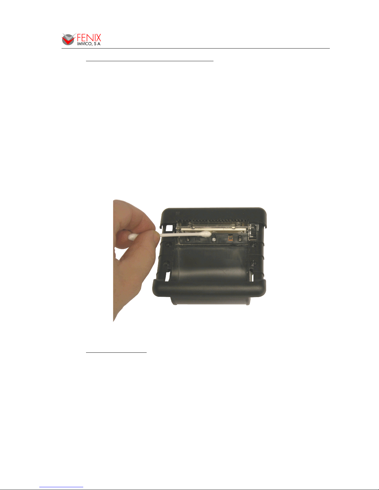
2.3- CLEANING PROCEDURE AND PRECAUTIONS
In order to clean the thermal print head, proceed as indicated by the following steps:
1- Unplug the power supply cable and open the front door.
2- Remove the paper roll and the thermal print head will be accessible from downwards.
3- Soak a cotton sponge in alcohol (ethanol, methanol or IPA), and rub it gently along the
thermal head in order to remove the possible accumulation of paper particles.
4- Wait for alcohol to evaporate before inserting the paper roll and closing the cover.
FENIX recommends cleaning the thermal print head periodically (every 2 or 3 months) in order
to keep an optimal print quality.
NOTES:
The print head may be hot after printing. Make sure it has thoroughly cooled down
before proceeding to clean it.
Never touch the thermal elements of the print head with your hands.
Never use metallic or piercing elements to clean the print head, as they could scratch it.
Fig. 1 - Thermal print head cleaning
2.4- RECOMMENDATIONS
• The plug has to be located near the printer and has to be easily obtainable.
• Before connecting any communication data cable, check the printer is working properly by
executing the self-test.
• Set the EPC1800 in a place where the connection cables do not suffer stretching or cross with
each other.
• IMPORTANT!!! Since the printer demands high current peaks during operation it is advisable to
make the power supply cables the shortest possible.
6 of 53
EPC1800 SERIES OPERATION MANUAL
3 – GENERAL SPECIFICATIONS
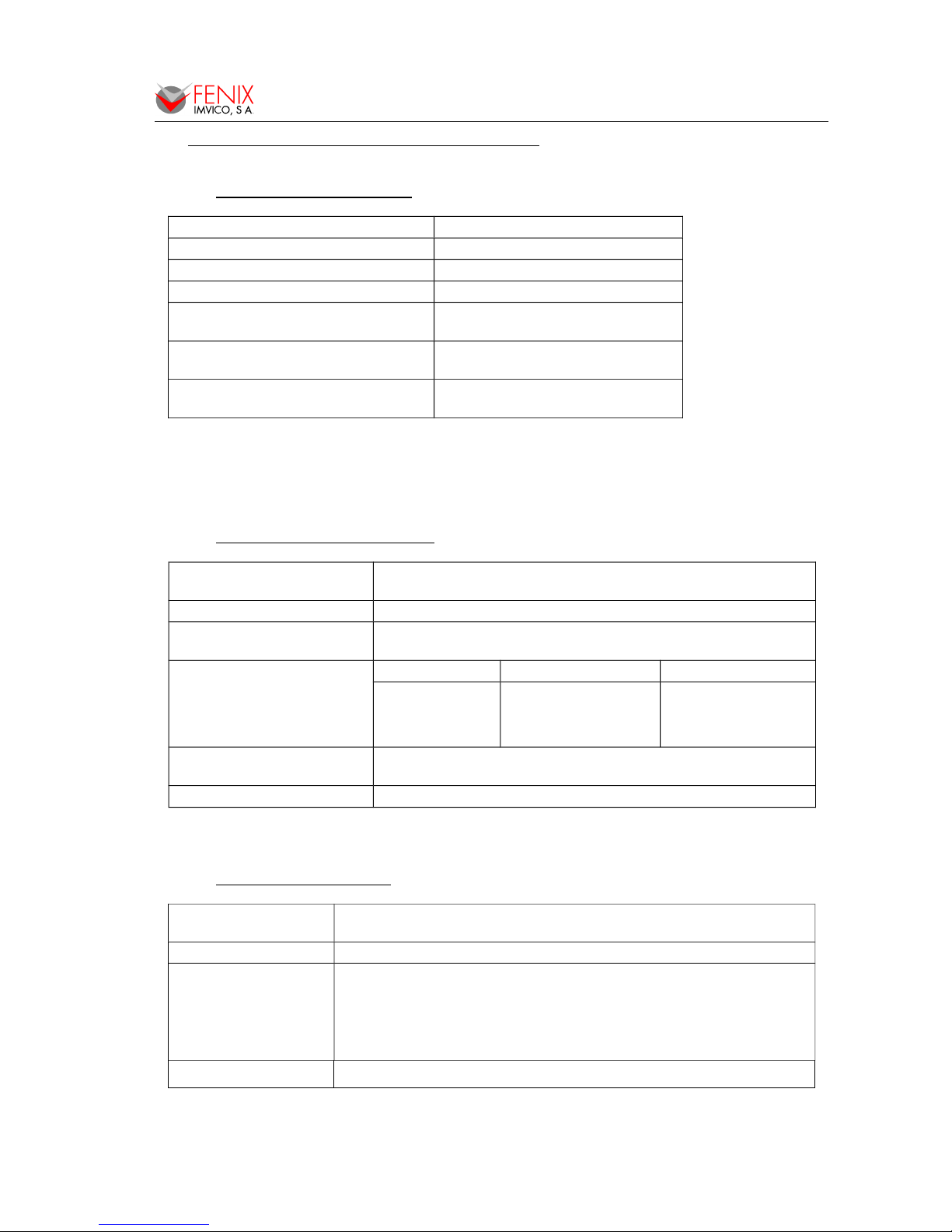
3.1- PRINTING SPECIFICATIONS
Printing method Thermal line printing
Dot density 203 x 203 dpi
(1)
Printing direction Unidirectional with friction feed
Printing width 48 mm (384 dots)
Printing speed
High speed mode: up to 100mm/s
(2)
37mm/s for the 5V version
Paper feed speed
100mm/s (continuous paper feed)
37mm/s for the 5V version
Characters per line (default)
A font: 24
B font: 32
(1)
‘dpi’: dots per inch. 1 inch = 25.4mm; 203 dpi = 8 dots per mm
(2)
Printing speed could vary depending on the print head temperature as well as the
command processing and the data transmission speed. Low transmission speed could
cause intermittent printing. It is recommended to transmit data to the printer as quickly
as possible.
3.2- CHARACTER SPECIFICATIONS
Character per line (default)
Font A: 24
Font B: 32
Character spacing (default) 0.5mm (4 dots)
Character structure
Font A: 12 x 24 dots (1.5 x 3 mm). (default)
Font B: 8 x 16 dots (1 x 2 mm).
Character size (mm)
(1)
Font A WxH(mm) – cpl
(2)
Font B WxH(mm) – cpl
Standard
Double-width
Double-height
Double width/height:
1.5 x 3 – 24
3 x 3 – 12
1.5 x 6 – 24
3 x 6 – 12
1 x 2 – 32
2 x 2 – 16
1 x 4 – 32
2 x 4 – 16
Number of characters
Alphanumeric characters: 95
Extended Graphics: 128 per page
Line spacing (default) 1,875mm (15 dots)
(1)
Characters can be scaled up to 64 times bigger than their normal size.
(2)
‘cpl’: characters per line.
3.3- PAPER SPECIFICATIONS
Paper roll size
Width: 58 +0/-1mm, (25 m approx.)
Maximum outside diameter: 45 mm
Paper type Thermal
Paper specifications
At –5ºC to 50ºC TF50KS-E2D (59µm paper )
TF77KS-E2 (95µm paper)
TL69KS-HG76 (label paper)
TL51KS-R2 and TL69KS-R2 (high heat-resistant paper)
At 5ºC to 40ºC TW80KK-S (2-ply thermal paper)
From Nippon Paper Industries
Paper loading Easy loading by accessible paper door.
7 of 53
EPC1800 SERIES OPERATION MANUAL
3.4- COMMUNICATIONS INTERFACE
Serial Serial interface RS232/TTL (baud options 203400, 115200, 38400, 19200, 9600)
USB USB 2.0 480Mbit/s
3.5- INTERNAL BUFFER
The standard EPC1800 printer has a 32 Kbytes internal memory buffer, whose functionality is
dynamically shared by the receiving buffer.
The buffer is being filled at the same time that buffered data is being printed, for that reason high
transmission speed is required in order to ensure that data is available for printing at any time. Data
transfer of at least 115200 bauds or USB connection increase the printing performance substantially.
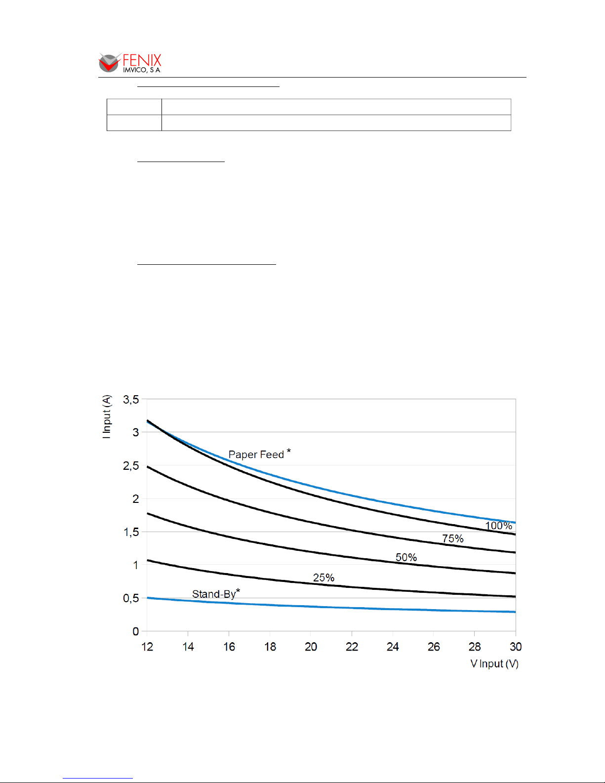
3.6- ELECTRICAL SPECIFICATIONS
Power supply: 5VDC ± 10% or 12-24VDC ± 10%
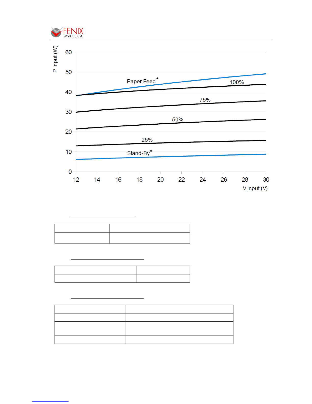
Consumption: The figures below show the relationship between average current and power
consumption with the input voltage at a ambient temperature of 25ºC. Each
graph contains 6 parameters corresponding to when printer is in Stand-by, when
the printer is just feeding paper, and when the 25%, 50%, 75% and 100% the
dots are energized and paper is being feed at the same time. In both graphs,
parameters in blue have been multiplied by 10 for better representation.
*Paper Feed and Stand-by parameters are shown multiplied by 10.
Fig. 2 - Current consumption vs input voltage (12-24VDC version)
8 of 53
EPC1800 SERIES OPERATION MANUAL
*Paper Feed and Stand-by parameters are shown multiplied by 10.
Fig. 3 - Power consumption vs input voltage (12-24VDC version)
3.7- BARCODE SPECIFICATIONS
Standard barcodes EAN-13, CODE39, ITF, CODE128
2D barcodes QR, AZTEC
3.8- MECHANICAL SPECIFICATIONS
Overall dimensions (W x D x H) 89.2 x 65.6 x 89.4mm
Weight (without paper) 130g
3.9- ENVIRONMENTAL CONDITIONS
Operating temperature -20 to 70ºC
Storage temperature -30 to 80ºC (without paper, in a dry place)
Life span (at 25ºC )
Activation pulse resistance
100 millions pulses or more (print ratio=12’5%).
Abrasion resistance 50 Km or more
9 of 53
EPC1800 SERIES OPERATION MANUAL
4 – INSTALLATION
4.1- EPC1800 INSTALLATION CONSIDERATIONS
There are some general considerations to take into account when installing the EPC1800 printer.
A wrong installation may cause many issues like paper jam, difficult maintenance of the printer,
difficulty in changing the paper roll, etc. Moreover, a correct installation can prevent the printer from
being damaged by external agents, such as weather or vandalism.
This printer is designed to be installed vertically or horizontally in a case, closet, or another kind of
appropriate chassis.
The basic points that a correct installation must follow are:
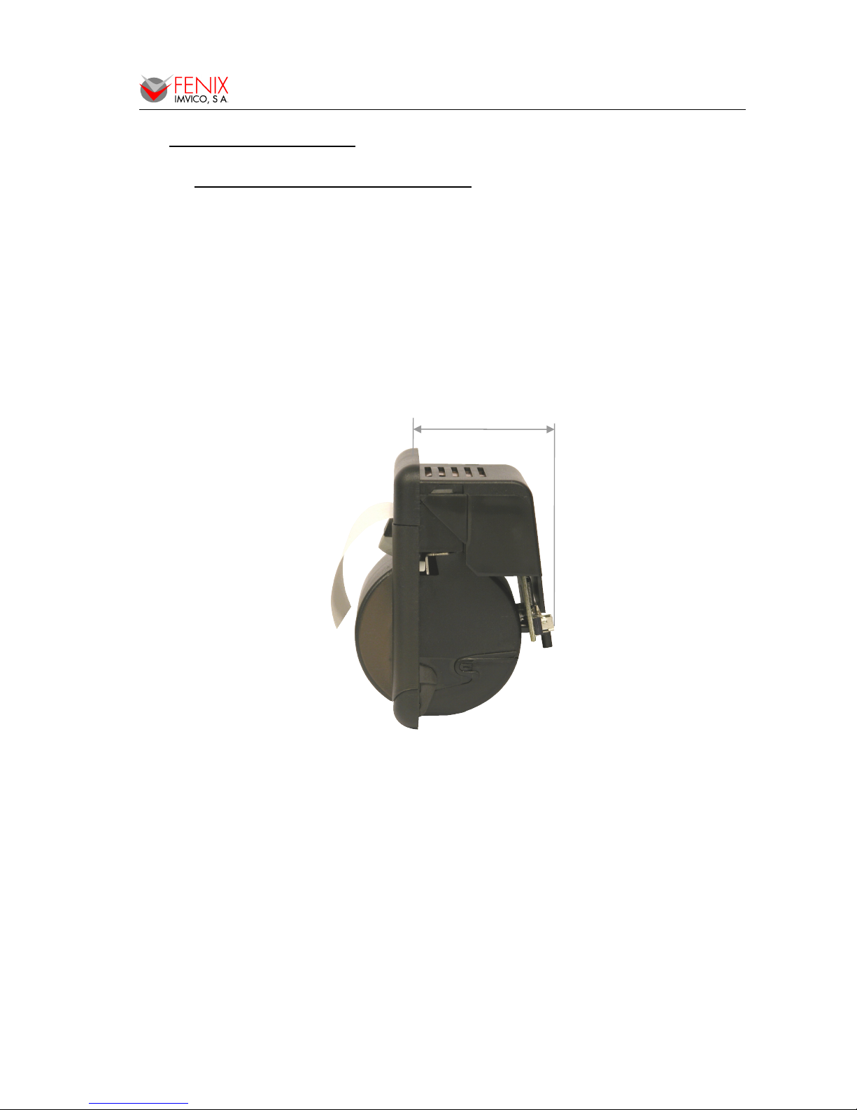
• Allow enough space and accessibility to reach the maintenance procedure points in case it
is needed. Take notice all user accessible parts in the printer.
Fig. 4 - EPC1800 accessibility
• Consider if the printer is going to be attached first to the panel and then connected or the
other way round. The EPC1800 allows both ways but cable length and some other variables
should have been taken into consideration.
• Allow enough room in front of the printer in order to be able to open completely the door.
This printer has been designed to ease the installation process and maintenance. Please follow the
recommendations below so there should not be any issue related to it.
• The printer must be set onto the user’s chassis and screwing it from outside. To do so cut a
window with the dimensions indicated on the figure and thread four holes as shown.
10 of 53
Minimum closet depth: 44mm
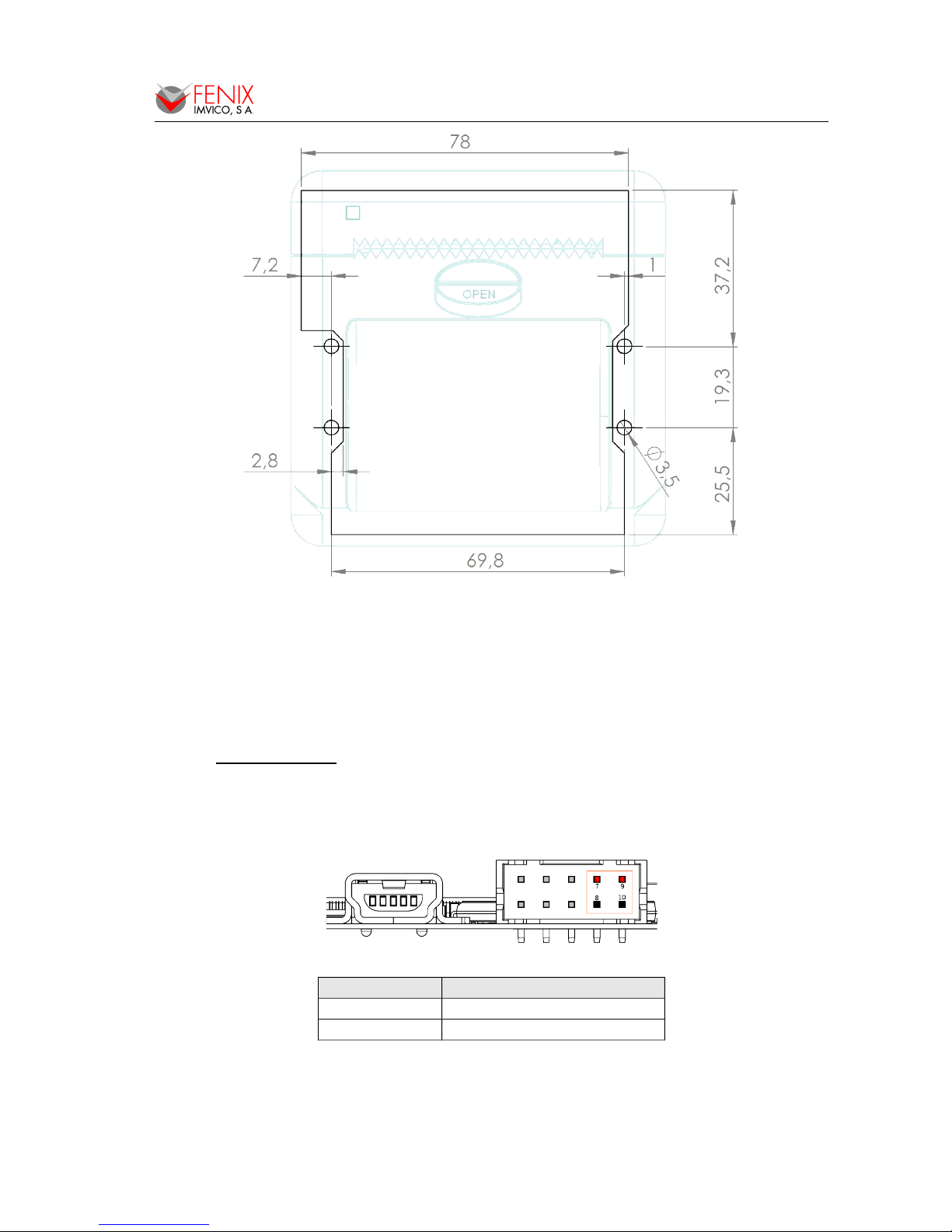
EPC1800 SERIES OPERATION MANUAL
Fig. 5 - Fixing holes and window to be cut on the mounting wall (dimensions in mm)
• All the wiring has been designed to allow the user to firstly connect the cables and then
screw the printer onto the panel although the other way is also possible. If it is difficult to
access the rear side of the printer it is advisable to connect all the cables first and perform a
self-test before fixing the printer to the mounting wall.
4.2- POWER SUPPLY
The EPC1800 is powered by an external power supply by means of four pins of the shared
connector that is also used for RS232 communication. Although the connector is polarized if forced it
could be connected inverted so it is very important to observe polarity before plugging the connector in.
Fig. 6 - Power supply connector J1.
Pin number Description
7, 9 VIN (5VDC or 12-24VDC)
8, 10 GND
The power supply female connector must be a:
Housing: PHDR-10VS (JST Ref.)
Terminal: SPHD-001T-P0.5 or equivalent.
Wire: 22 AWG or thicker (GND & VIN)
11 of 53

EPC1800 SERIES OPERATION MANUAL
NOTES:
(1) If the number of dots that are energized at the same time is increased, a higher current
will flow; therefore, a power supply with an adequate current capability must be used.
(2) When designing lines and bit images, take the printing ratio and print duty into
consideration. Print quality may be poor if the printing ratio (energizing pulses/dot line) or
print duty is high.
(3) Average energizing pulse width is defined as 64 of 192 dots/dot line that are energized.
WARNING: Beware not to invert the polarity of power supply. This may
irremediably damage the printer. Ensure that the voltage is the correct
one. Use the 4 terminals (4 wires) with 0.35mm² minimum section each.
NOTE ABOUT POWER SUPPLY:
The current demand depends on the density of the printout. A 60W power supply covers all
adverse possibility (see section 3.6- ELECTRICAL SPECIFICATIONS).
FENIX offers different power supplies as an accessory option (See APPENDIX B – HOW TO
ORDER). These power supplies which have been exhaustively tested are available in OPEN FRAME or
ENCLOSED version.
4.3- RS-232 SERIAL INTERFACE
4.3.1- RS-232 Serial interface specifications
• Data transmission type: Serial
• Synchronization: Asynchronous
• Flow control: None, Hardware and Xon/Xoff
• Signal levels (RS232): MARK = -3 to -15 V Logic ‘1’/OFF
SPACE = +3 to +15 V Logic ‘0’/ON
• Speed: 9600, 19200, 38400, 115200 and 230400 bauds.
• Data length: 8 bits
• Parity: none, even and odd
• Stop bits: Fixed to 1
• Connector (user side): JST PHDR-10VS (housing)
JST SPHD-001T-P0.5 (terminal) or similar.
NOTE: Speed and parity depend on the settings (refer to section 4.3.1- RS-232 Serial interface
specifications).
4.3.2- Change between online and offline mode
The printer is in offline mode:
1) When powering up or resetting the printer, until the printer is ready to receive data.
2) When the door is opened.
3) After pressing the button while the paper advances.
4) When ‘out of paper’ causes the printer to stop printing.
5) When the power supply has a temporal abnormal voltage change.
6) When an error has occurred.
4.3.3- Serial RS-232 interface pins assignment
The assignments of the terminals of the RS-232 connector and the functions of its signals are
described in the following figures:
12 of 53
EPC1800 SERIES OPERATION MANUAL
Pin number Signal name Function
3 SG Signal ground
4 RTS Indicates whether the printer is busy
5 TXD Data transmission line
6 RXD Data reception line
Fig. 7 - Serial RS-232 interface pins
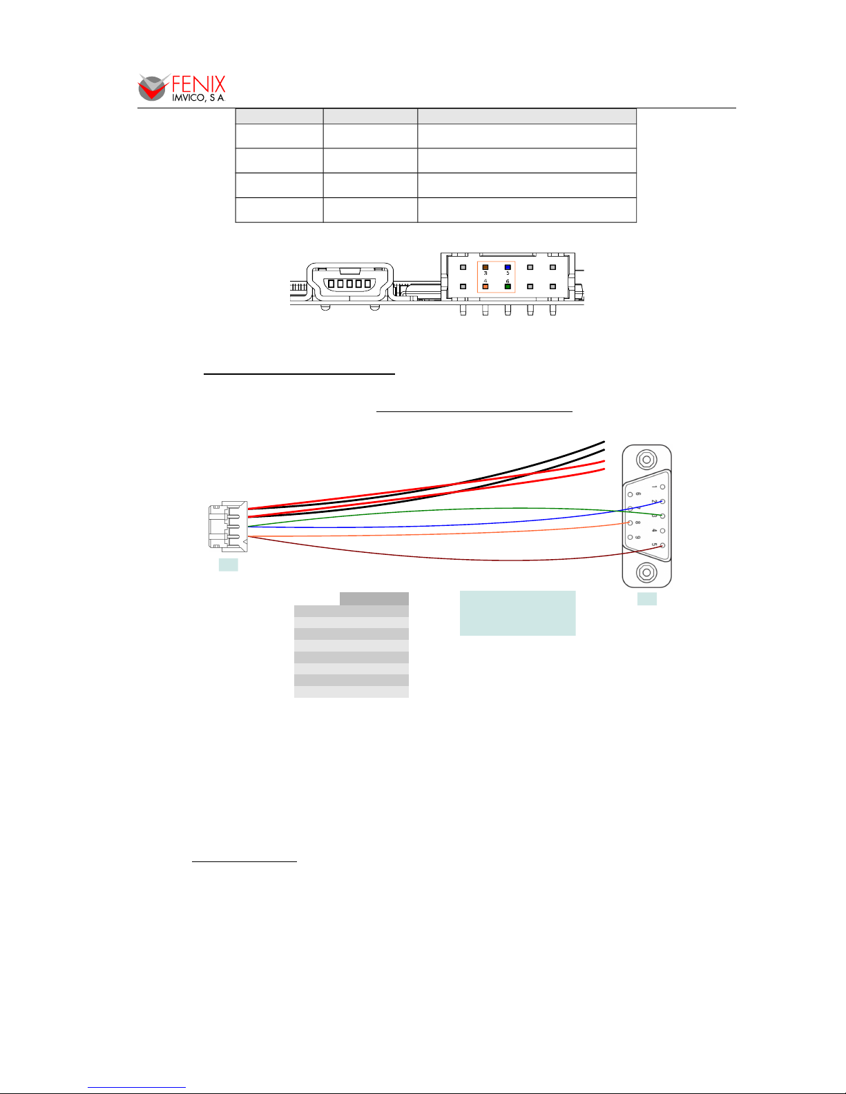
4.3.4- Power supply and RS232 cable
According to previous sections, the figure below shows the pinout and elements required to make
power supply and RS232 cable (see also APPENDIX B – HOW TO ORDER).
Fig. 8 - PC serial and power cable
NOTES:
• Same configuration in the printer and in the host system should be set.
• The communication protocol should be set properly so that the transmitted data can be
received without errors.
4.4- USB INTERFACE
The EPC1800 USB interface has the following general features:
• USB specification USB 2.0 (480Mbits/s full speed)
• Transfer type Bulk
• Maximum receive/transmit endpoint size 64 bytes
• Current consumption from USB bus 2mA max.
13 of 53
CN1 CN2
SGND 3
5
RTS 4
8
TxD 5
2
RxD 6
3
VIN 7
GND 8
VIN 9
GND 10
CN1: HOUSING JST PHDR-10VS
TERMINAL SPHD-001T-P0.5
WIRE (GND & VIN) 22 AWG
CN2: DB9 FEMALE
CN1
CN2
EPC1800 SERIES OPERATION MANUAL
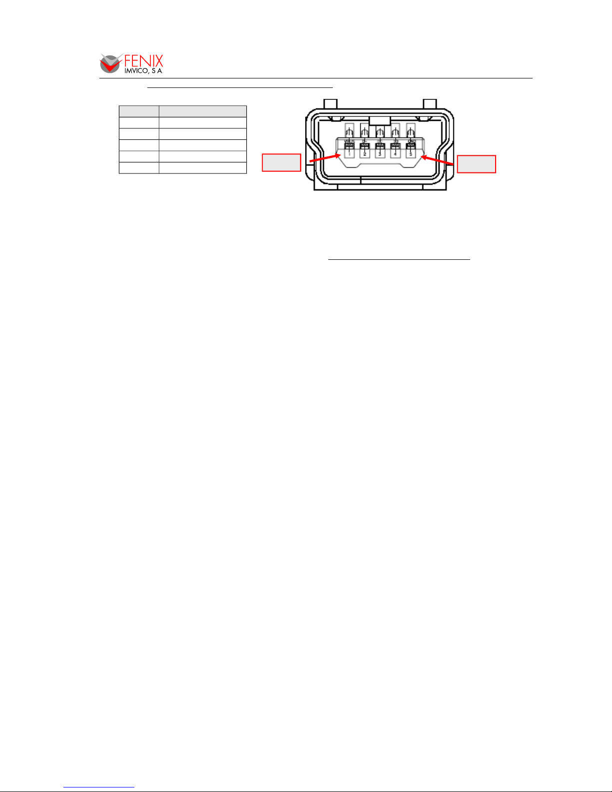
4.4.1- Assignments of USB connector terminals
Pin Signal name
1 VBUS
2 D –
3 D+
4 GND
5 NC
Fig. 9 - EPC1800 USB connector.
USB Mini-B series connector has to be used (see APPENDIX B – HOW TO ORDER).
14 of 53
Pin #5
Pin #1

YES
NO
EPC1800 SERIES OPERATION MANUAL
5 – BASIC OPERATIONS
5.1- PAPER LOADING
One of the most highlighted features of the EPC1800 printer is paper loading, which becomes very
simple if the following steps are executed:
a) Open the printer’s front door by pressing the cover “OPEN” button.
b) Insert the paper roll with the orientation shown in the picture, leaving
about 5mm of paper outside the printer.
Place the paper roll in the right direction. The thermal paper has
only one surface that can be printed (thermal side). In order to know
which one it is, just scratch the paper: the thermal side will show up
the track on.
c) Close the cover feeling the roller is latched again.
Fig. 10 - Paper orientation
5.2- BUTTON FUNCTIONS
• PAPER FEEDING: when the printer is powered on pressing the button will feed the paper.
The paper roller will not move under the following conditions:
- The paper roll end sensor detects a paper end.
- When the door is open.
- When another non-recoverable error is present.
• SELF-TEST MODE: If pressed on start-up with the door closed, it activates this mode.
• HEXADECIMAL MODE: In order to activate it, if the button is still pressed when the full Self-
test has been printed, the printer will prompt the user to hold the button to enter this mode.
5.3- PAPER SENSORS
The EPC1800 has one photo sensor for ‘out of paper’ detection.
The out of paper sensor has the basic function of informing the printer controller about the
existence of paper (on the printing line). Because there are some actions (for instance, printing without
paper) that could seriously damage the mechanism, this error blocks all the printer activities.
The final user can detect these errors by means of the front LED, and the application developer
can test them through the DEL EOT command, being able to act accordingly.
NOTES:
• Use paper rolls that meet the specifications indicated in this manual.
• Do not open the printer cover during the printing operation.
• Close the cover correctly, checking that the ‘PAPER OUT’ LED turns green.
5.4- DOOR OPEN SENSOR
The EPC1800 has a dedicated mechanical sensor to detect the opening of the door. When the
door is open the LED will light red and the printer will block all the activity related to printing.
15 of 53

EPC1800 SERIES OPERATION MANUAL
NOTE: If EPC1800 detects no paper or platen open while is printing it will stop the
communication in order not loose any data.
5.5- LED INDICATOR
EPC1800 has one indicator led to visually inform about the printer status. When the LED lights or
blink GREEN means normal operation. The LED blinks ORANGE whether the EPC1800 has detect a
non-recoverable error. The LED blinks RED when a recoverable error has been occurred. If the lights
RED, there is no paper or the door has been opened. See section 5.7- ERROR PROCESSING
5.6- SPECIAL PRINTING MODES
Besides the normal printing mode in which all the received data are printed according to the
settings or conditions fixed by the commands, the EPC1800 printer allows three special working modes:
self-test mode, programming mode and the hexadecimal mode.
5.6.1- Self-test mode
The printer provides the selftest mode with two different
functionality: showing information
of the settings of that particular
printer model and verifying the
printing.
To enter the self-test mode,
the printer must be powered on
while keeping pressing the button.
The EPC1800 will start
printing a report, which allows
checking the features of this
particular model, like the firmware
current version, control functions of
the communications protocol, and
so on.
If, once this printing has been
finished, the button is kept pressed;
the printer will start printing
continuously and repetitively a
character map until it finally
concludes the self-test by printing ‘*
* completed * *’. This second
option of the self-test mode has the
goal of validating the printing speed
and quality.
At the end of the self-test
page there are few lines showing
the three different maintenance
counts:
1- Times that the printer has been
switched on.
2- Time (in half hours) that the printer has been powered on.
3- Meters of paper printed.
16 of 53
Fig. 11 - SELF-TEST
mode example
FENIX IMVICO
EPC1800 V1.0.1
SERIAL PORT SETTINGS
Data bits: 8 (fixed)
Stop bits: 1 (fixed)
Baud rate: 115200 bauds
Parity bit: No parity
Protocol: Hard.RTS/CTS
USB PORT SETTINGS
USB V2.0 480Mbits/s
DEFAULT TEXT SETTINGS
Set character EUROPE 437
Table A (12x24 dots)
Character Height: 1
Character Width: 1
Character space: 4
Line space: 15
Print density: Standard
Carry Return: Disabled
EXTERNAL TABLES:
(No table loaded)
LOGOS LOADED:
(No logo loaded)
* RECORDS *
Serial num. 0FE057057142
On/Off times: 100
Meters: 100
Time ON(H:M): 0:10
!”#$%&'()*+,-./01234567
!”#$%&'()*+,-./012345678
”#$%&'()*+,-./0123456789
#$%&'()*+,-./012345679 :
$%&'()*+,- ./012345679 : ;
%&'()*+,-./0123456779 : ; <
&'()*+,-./0123456779 : ; < '()*+,-./0123456779 : ; < - >
()*+,-./0123456779 : ; < - >?
)*+,-./0123456779 :;< - >?@
*+,-./0123456779 :;< - >?@A
+,-./0123456779 :;< - >?@AB
,-./0123456779 :;< - >?@ABC
.
.
.
.
.
vwxyz{ | }~ !”#$%&'()*+,
wxyz{ | }~ !”#$%&'()*+,xyz{ | }~ !”#$%&'()*+,-.
yz{ | }~ !”#$%&'()*+,-./
z{ | }~ !”#$%&'()*+,-./0
{ | }~ !”#$&'()*+ , - . /01
| }~ !”#$&'()*+ , - . /012
* * completed * *
 Loading...