

Fenix EPC1200 Operation Manual

E
PC1
2
IF120
0
00
T
INTE
R
HER
M
FACE
ope
r
AL
and PT
ation
m
March 2
PRI
N
R2 Sta
n
anu
a
0
08
TE
R
d-Alo
n
l
SE
R
e Print
e
IES

EPC1200 SERIES OPERATION MANUAL
2/56
INDEX
1 – INTRODUCTION .................................................................................................................................. 4
2 – IMPORTANT NOTES ON EPC1200 THERMAL PRINTER HANDLING ............................................. 5
2.1- SAFETY PRECAUTIONS ......................................................................................................... 5
2.2- ABSOLUTE MAXIMUM RATINGS ........................................................................................... 5
2.3- CLEANING PROCEDURE AND PRECAUTIONS .................................................................... 6
2.4- RECOMMENDATIONS ............................................................................................................. 6
3 – GENERAL SPECIFICATIONS .............................................................................................................. 7
3.1- PRINTING SPECIFICATIONS .................................................................................................. 7
3.2- CHARACTER SPECIFICATIONS ............................................................................................. 7
3.3- PAPER SPECIFICATIONS ....................................................................................................... 7
3.4- PAPER LOADING ..................................................................................................................... 7
3.5- INTERNAL BUFFER ................................................................................................................. 8
3.6- ELECTRICAL SPECIFICATIONS ............................................................................................. 8
3.7- ENVIRONMENTAL CONDITIONS ........................................................................................... 8
4 – INSTALLATION .................................................................................................................................... 9
4.1- EPC1200 INSTALLATION CONSIDERATIONS ...................................................................... 9
4.2- POWER SUPPLY ................................................................................................................... 11
4.3- RS-232 SERIAL INTERFACE ................................................................................................. 13
4.3.1- RS-232 Serial interface specifications ....................................................................... 13
4.3.2- Change between online and offline mode .................................................................. 13
4.3.3- Serial RS-232 interface pins assignment ................................................................... 13
4.3.4- PC serial interface connection ................................................................................... 14
4.4- CENTRONICS PARALLEL INTERFACE ............................................................................... 14
4.4.1- Compatibility mode (Centronics compatible) ............................................................. 14
4.4.2- Reverse mode (Data transmission from the printer to the host system) ................... 15
4.4.3- Parallel interface pins assignment for each mode ..................................................... 16
4.4.4- PC parallel interface connection ................................................................................ 17
4.5- USB INTERFACE ................................................................................................................... 17
4.5.1- Assignments of USB connector terminals USB ........................................................ 18
5 – BASIC OPERATIONS ......................................................................................................................... 19
5.1- PAPER LOADING ................................................................................................................... 19
5.2- BUTTON FUNCTIONS ........................................................................................................... 19
5.3- PAPER SENSORS ................................................................................................................. 19
5.4- OPEN PLATEN SENSOR ....................................................................................................... 20
5.5- NEAR-END PAPER SENSOR ................................................................................................ 20
5.6- LED INDICATOR .................................................................................................................... 20
5.7- SPECIAL PRINTING MODES ................................................................................................ 20
5.7.1- Self-test mode ............................................................................................................ 20
5.7.2- Programming mode .................................................................................................... 21
5.7.3- Hexadecimal dump mode .......................................................................................... 22
5.8- ERROR PROCESSING .......................................................................................................... 23
5.8.1- Error types .................................................................................................................. 23
5.8.2- Printer operation when an error happens .................................................................. 24
5.8.3- Data reception error (serial interface only)
................................................................. 24
5.8.4- Flow diagram of the error detection for the serial port ............................................... 24
5.8.5- Flow diagram of the error detection for the parallel port ............................................ 25
6 – CONTROL COMMANDS .................................................................................................................... 26
6.1- COMMAND NOTATION ......................................................................................................... 26
6.2- TERM DEFINITIONS .............................................................................................................. 26
6.3- DESCRIPTION OF THE CONTROL COMMANDS ................................................................ 27
APPENDIX A – SPECIFICATIONS .......................................................................................................... 43
APPENDIX B – MECHANICAL DIMENSIONS ......................................................................................... 44
APPENDIX C – HOW TO ORDER ........................................................................................................... 45
APPENDIX D – CODE128 BAR CODE .................................................................................................... 46
D.1 Description of the CODE128 Bar Code .................................................................................. 46
D.2 Printable characters in CODE SET A ..................................................................................... 47
D.3 Printable characters in CODE SET B ..................................................................................... 48
D.4 Printable characters in CODE SET C ..................................................................................... 49
APPENDIX E – INTERNAL CHARACTER TABLES ................................................................................ 50

EPC1200 SERIES OPERATION MANUAL
3/56
APPENDIX F – TESTING SOFTWARE ................................................................................................... 51
APPENDIX G – INTERFACE IF1200 ....................................................................................................... 53
APPENDIX H – PTR2 ............................................................................................................................... 55
FIGURES AND TABLES
Fig. 1. - Thermal print head cleaning ......................................................................................................... 6
Fig. 2. - EPC1200 accessibility .................................................................................................................. 9
Fig. 3. - Fixing holes and window to be cut on the mounting wall ........................................................... 10
Fig. 4. - Application of a self-stand PTR2 with the EPC1200. ................................................................. 10
Fig. 5. - Power supply connector CON1. ................................................................................................. 11
Fig. 6. - FENIX supplied 5VDC power modules. ...................................................................................... 12
Fig. 7. - Current consumption example .................................................................................................... 12
Fig. 8. - Serial RS-232 interface pins ....................................................................................................... 13
Fig. 9. - PC serial cable ............................................................................................................................ 14
Fig. 10. - Timing diagram of data reception ............................................................................................. 15
Fig. 11. - Parallel interface pins ............................................................................................................... 16
Fig. 12. - PC parallel cable ....................................................................................................................... 17
Fig. 13. - EPC1200 USB connector. ........................................................................................................ 18
Fig. 14. - Paper orientation ...................................................................................................................... 19
Fig. 15. - SELF-TEST mode example ...................................................................................................... 20
Fig. 16. - PROGRAMMING MODE example ........................................................................................... 21
Fig. 17. - HEXADECIMAL DUMP mode example .................................................................................... 22
Fig. 18. - LED Blinking sequence (RED) ................................................................................................. 23
Fig. 19. - Serial port error flow diagram ................................................................................................... 24
Fig. 20. - Nibble mode phase transitions ................................................................................................. 25
Fig. 21. - Code128 bar code .................................................................................................................... 39
Fig. 22. - Logo loading ............................................................................................................................. 42
Fig. 23. – Mechanical dimensions ........................................................................................................... 44
Fig. 24. – Demo Program ........................................................................................................................ 51
Fig. 25. – IF1200 ...................................................................................................................................... 53
Fig. 26. – IF1200 Mechanical Dimensions ............................................................................................... 54
Fig. 27. – PTR2 Fixing Options ................................................................................................................ 55
Table 1. - Pins Assignments of RS-232 connector terminals .................................................................. 13
Table 2. - Timing of parallel communication protocol .............................................................................. 15
Table 3. - PC parallel connector (DB25) .................................................................................................. 16
Table 4. - Command List .......................................................................................................................... 27

EPC1200 SERIES OPERATION MANUAL
4/56
The EPC1200 is a high performance thermal panel printer series. Its compact and functional
design covers many professional uses (as in supermarkets, hotels, hospitals, restaurants, and so on.) It
is capable of printing text, graphics, logo and barcodes. It can be used in laboratories, industrial and
professional environments.
The main features of the EPC1200 Series are:
• Simple installation and easy maintenance.
• Low noise thermal printing.
• Paper width: 58 mm.
• High reliability: 100 million pulses. Abrasion resistance: 50 Km.
• Power supply, two options: 5VDC or 12-24VDC, depending on the interface.
• No-paper sensor.
• Near-to-end paper sensor (only on the 12-24VDC models)
• Up to 45 mm paper roll diameter.
• High speed printing up to 90mm/s (EPC1250 prints up to 50mm/s).
• Printing resolution: 8 dots/mm (203 dpi).
• Passive paper cut.
• Interface: - Option 1: IEEE 1284 parallel and serial RS232C data input interface
on-board (up to 115200bps).
- Option 2: Universal Serial Bus (USB) communications port on-board.
• Two internal character fonts (A font = 12x24 dots. B font = 8x16 dots).
• Scalable font (independent scale in X/Y-axis), up to 64 times.
• Programmable character and line space.
• Bold and reverse character capabilities
• Graphic bitmap printing capabilities.
• Several format Bar Code (EAN13, Code39, Code128 and ITF)
• Control code based on ESC/POS commands (*).
• Hexadecimal mode for easy software debugging.
• Automatic paper load.
• Three maintenance counters (On/Off times, Half hours, Meters)
• Operating temperature range (0ºC to +50ºC).
• Storage temperature range (-20ºC to +70ºC).
• Self test, hexadecimal mode and configuration mode features.
• Logo load capability, through Windows driver.
• Windows 2000 and XP drivers and demo/configuration program.
• Linux Driver.
•
(*) ESC/POS are registered trademarks of Seiko Epson Corporation.
The EPC1200 Printer Series comprises the following models:
EPC1200-5 5VDC, 90mm/s printing speed, serial & parallel interface
EPC1200-12 12-24VDC, 90mm/s printing speed, serial & parallel interface
EPC1200-12-U 12-24VDC, 90mm/s printing speed, USB interface
EPC1250 5VDC, 50mm/s printing speed, serial & parallel interface
This manual is the printer operations’ guide and is intended for the designer’s application. The
following sections contain a detailed description of both hardware and configuration software that allow
obtaining the maximum benefit of the printer capabilities.
1 – INTRODUCTION

EPC1200 SERIES OPERATION MANUAL
5/56
In order to preserve the life of the printer, it is necessary to keep in mind some precautions on the
handling of the EPC1200 printer. Please read carefully the following points in order to make a good use
of the printer.
2.1- SAFETY PRECAUTIONS
• Before using the printer, read carefully section 2-INSTALLATION.
• NEVER connect the external power supply with the wrong polarity. This could permanently
damage the printer.
• Turn off the printer immediately if it produces smoke, a strange smell or an unusual noise. Keeping
on using the printer could cause fire. Unplug the equipment immediately and contact your official
distributor.
• NEVER connect cables with different connectors from the ones mentioned in this manual. Failing
on doing so could permanently damage the printer.
• Use a power supply whose output voltage is within the specification range stated in this manual.
Over voltage can permanently damage the printer. Under voltage can cause malfunctions.
• NEVER wet EPC1200 thermal printer with water or any other liquid. If any liquid is spilled inside
the equipment, unplug the power cable immediately and contact the technical service.
• Make sure the printer is on a steady, securely fixed surface. If the printer falls down, it could break
or damage.
• NEVER use the printer in high humidity or in locations with high risk of fire.
• NEVER place heavy objects on top of the printer and never lean on it.
• NEVER put any object inside of the printer, as it could cause hardware damage on it, such as
short-circuit, print head breaking or general failure of the printer.
• NEVER shake the printer.
• NEVER disassemble or modify the hardware of the printer.
• NEVER try to repair the printer. Please contact your official distributor in case of failure.
• As the printer contains electromagnets (inside of the motor), it should not be used in excessively
dirty environments or places with dust or metal particles.
• NEVER print without paper loaded or without the cover closed, as the thermal print head life can
be highly shortened.
• Avoid touching accessible parts with metallic objects, such as screwdrivers or tweezers, the print
head thermal elements as well as the electronic printed circuit. They are delicate parts.
• NEVER touch with bare hands the areas around the print head and the motor surface as they
become very hot during and just after printing; wait 15 seconds after printing to let them cool down.
• NEVER touch the surfaces of the print head thermal elements or the electronic printed circuit, as
dust and dirt can stick to their surface and cause damage by electrostatic discharge. Moreover,
some electronic components can get very hot during operation.
• The thermal paper contains Na+, K+ and Cl- ions that can cause harm to the print head elements.
Therefore, use only the specified paper.
• If the printer has not been used for long period of time and the paper was loaded, the paper could
become deformed by the drive roller pressure. It is recommended to make it advance at least 30
mm before printing again.
• For safety reasons, unplug the printer if it is not going to be used over a long period of time.
• Do not print continuously (without stopping) for more than 6 minutes.
2.2- ABSOLUTE MAXIMUM RATINGS
Supply voltage
EPC1200-12 . .
. . . . . . . . . . . . . . . . . . . . . . . . . . . . . . . . . . . . . . . . . . . . . . . . . . . . . . . . . . . . +30 V
EPC1200-5 . .
. . . . . . . . . . . . . . . . . . . . . . . . . . . . . . . . . . . . . . . . . . . . . . . . . . . . . . . . . . . . . +10 V
EPC1250 . . . . . . . . . . . . . . . . . . . . . . . . . . . . . . . . . . . . . . . . . . . . . . . . . . . . . . . . . . . . . . . . +5.6 V
Storage temperature range . . . . . . . . . . . . . . . . . . . . . . . . . . . . . . . . . . . . . . . . . . . . . . −20°C to 70°C
2 – IMPORTANT NOTES ON EPC1200 THERMAL PRINTER HANDLING

EPC1200 SERIES OPERATION MANUAL
6/56
2.3- CLEANING PROCEDURE AND PRECAUTIONS
In order to clean the thermal print head, proceed as indicated by the following steps:
1- Unplug the power supply cable and open the front door.
2- Remove the paper roll and the thermal print head will be accessible from downwards.
3- Soak a cotton sponge in alcohol (ethanol, methanol or IPA), and rub it gently along the
thermal head in order to remove the possible accumulation of paper particles.
4- Wait for alcohol to evaporate before inserting the paper roll and closing the cover.
FENIX recommends cleaning the thermal print head periodically (every 2 or 3 months) in order
to keep an optimal print quality.
NOTES:
9 The print head could be hot after printing. Make sure it has thoroughly cooled down
before proceeding to clean it.
9 Never touch the thermal elements of the print head with your hands.
9 Never use metallic or piercing elements to clean the print head, as they could scratch it.
Fig. 1. - Thermal print head cleaning
2.4- RECOMMENDATIONS
• The plug has to be located near the printer and has to be easily obtainable.
• Before connecting any communication data cable, check the printer is working properly by
executing the self-test.
• Set the EPC1200 in a place where the connection cables do not suffer stretching or cross with
each other.
• IMPORTANT!!! Since the printer demands high current peaks during operation it is advisable to
make the power supply cables the shortest possible. Otherwise the supply voltage could fall
below limits causing malfunction of the printer, especially on the 5VDC model.

EPC1200 SERIES OPERATION MANUAL
7/56
3.1- PRINTING SPECIFICATIONS
EPC1200 EPC1250
Printing method Thermal line printing
Dot density 203 dpi x 203 dpi
(1)
Printing direction Unidirectional with friction feed
Printing width 48 mm (384 dots)
Printing speed
(2)
High speed mode:
up to 90mm/s
up to 50mm/s
Paper feed speed 90 mm/s (continuous
paper feed)
50 mm/s (continuous
paper feed)
Characters per line (by default):
A font: 24
B font: 32
Space between characters (by
default):
4 dots (0.5 mm)
Line spacing (by default): 3.75mm
(1)
‘dpi’: dots per inch. 1 inch = 25.4mm; 203 dpi = 8 dots per mm
(2)
Printing speed could vary depending on the print head temperature as well as the
command processing and the data transmission speed. Low printing speed could
cause intermittent printing. It is recommended to transmit data to the printer as quickly
as possible.
3.2- CHARACTER SPECIFICATIONS
1) Number of characters: Alphanumeric characters: 95
Extended graphics: 128 per page
2) Character structure: A font: 12 x 24 dots (1.5 x 3 mm). (selected by default)
B font: 8 x 16 dots (1 x 2 mm).
3) Character size:
Standard Double height Double width Double width / Double height
Width x height cpl Width x height cpl Width x height cpl Width x height cpl
A Font 1,5 x 3 mm 24 1,5 x 6 mm 24 3 x 3 mm 12 3 x 6 mm 12
B Font 1 x 2 mm 32 1 x 4 mm 32 2 x 2 mm 16 2 x 4 mm 16
The space between the characters is not included. Characters can be scaled up to 64 times bigger than their
normal size.
cpl: characters per line.
3.3- PAPER SPECIFICATIONS
1) Paper type: thermal paper roll
2) Paper width: 58 +0/-1mm
3) Paper roll size: up to a maximum diameter of 45 mm
4) Specified thermal paper: At –5ºC to 50ºC Æ TF50KS-E2D (59μm paper)
TF77KS-E2 (95μm paper)
TL69KS-HG76 (label paper)
At –30ºC to 70ºCÆ TL51KS-R2 (High heat-resistant paper)
TL69KS-R2 (High heat-resistant paper)
At 5ºC to 40ºC Æ TW80KK-S (2-ply thermal paper)
From Nippon Paper Industries
3.4- PAPER LOADING
One of the main advantages of the EPC1200 printer series is its paper loading system. It can be
carried out by any final user without having to disassemble the printer or loading the paper in a complex
paper path.
3 – GENERAL SPECIFICATIONS
EPC1200 SERIES OPERATION MANUAL
8/56
10 12 14 16 18 20 22 24 26
500
1000
1500
2000
2500
3000
3.5- INTERNAL BUFFER
The standard EPC1200 printer has a 10 Kbytes internal memory buffer, whose functionality is
dynamically shared by the receiving buffer. The USB version has an additional 512 Kbyt es memory
buffer to fully enjoy the USB fast data sending features.
This big receiving buffer allows the printer working in the following way: Firstly, all data is buffered,
and afterwards the printing is performed at the maximum possible speed without being affected by the
communications time processing.
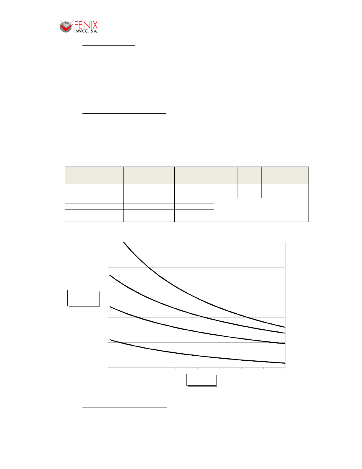
3.6- ELECTRICAL SPECIFICATIONS
- Power supply voltage: 5VDC+10%-3% or 12-24VDC±10% depending on the interface.
- Current consumption: The table and chart below show the current consumption for different
supply voltages. Measurements have been done for the following cases:
• Printer powered on (stand-by)
• Printer feeding paper but no printing
• Printer printing at rates of 25%, 50%, 75% and 100% of dots activated each line (chart)
3.7- ENVIRONMENTAL CONDITIONS
Temperature range: Working temperature: 0º to 50ºC.
Storage temperature: -25º to 70ºC with no paper loaded, in a dry place.
Printer Model Supply
Voltage
(V)
Stand-by
current
(mA)
Feeding paper
current
(mA)
25%
Printing
Ratio
50%
Printing
Ratio
75%
Printing
Ratio
100%
Printing
Ratio
EPC1250 5
210 500 1750 2780 4265 5390
EPC1200 5
395 850 2155 4250 5250 7150
EPC1200-X-12 / PTR2 12V 135 335
SEE CHART BELOW
EPC1200-X-12 / PTR2 15V 110 280
EPC1200-X-12 / PTR2 20V 90 220
EPC1200-X-12 / PTR2 24V 75 190
Average Current
Consumption
(mA)
Supply Voltage
(V)
25%
50%
75%
100%
EPC1200 SERIES OPERATION MANUAL
9/56
4.1- EPC1200 INSTALLATIO N CO NSIDERATIONS
There are some general considerations to take into account when installing the EPC1200 printer.
A wrong installation may cause many issues like paper jam, difficult maintenance of the printer,
difficulty in changing the paper roll, etc. Moreover, a correct installation can prevent the printer from
being damaged by external agents, such as weather or vandalism.
This printer is thought to be installed vertically in a bigger case or structure, or another kind of
appropriate chassis.
The basic points that a correct installation must follow are:
• Allow enough space and accessibility to reach the maintenance procedure points in case it
is needed. Take notice all user accessible parts in the printer.
• Consider if the printer is going to be attached first to the panel and then connected or the
other way round. The EPC1200 allows both ways but cable length and some other variables
should have been taken into consideration.
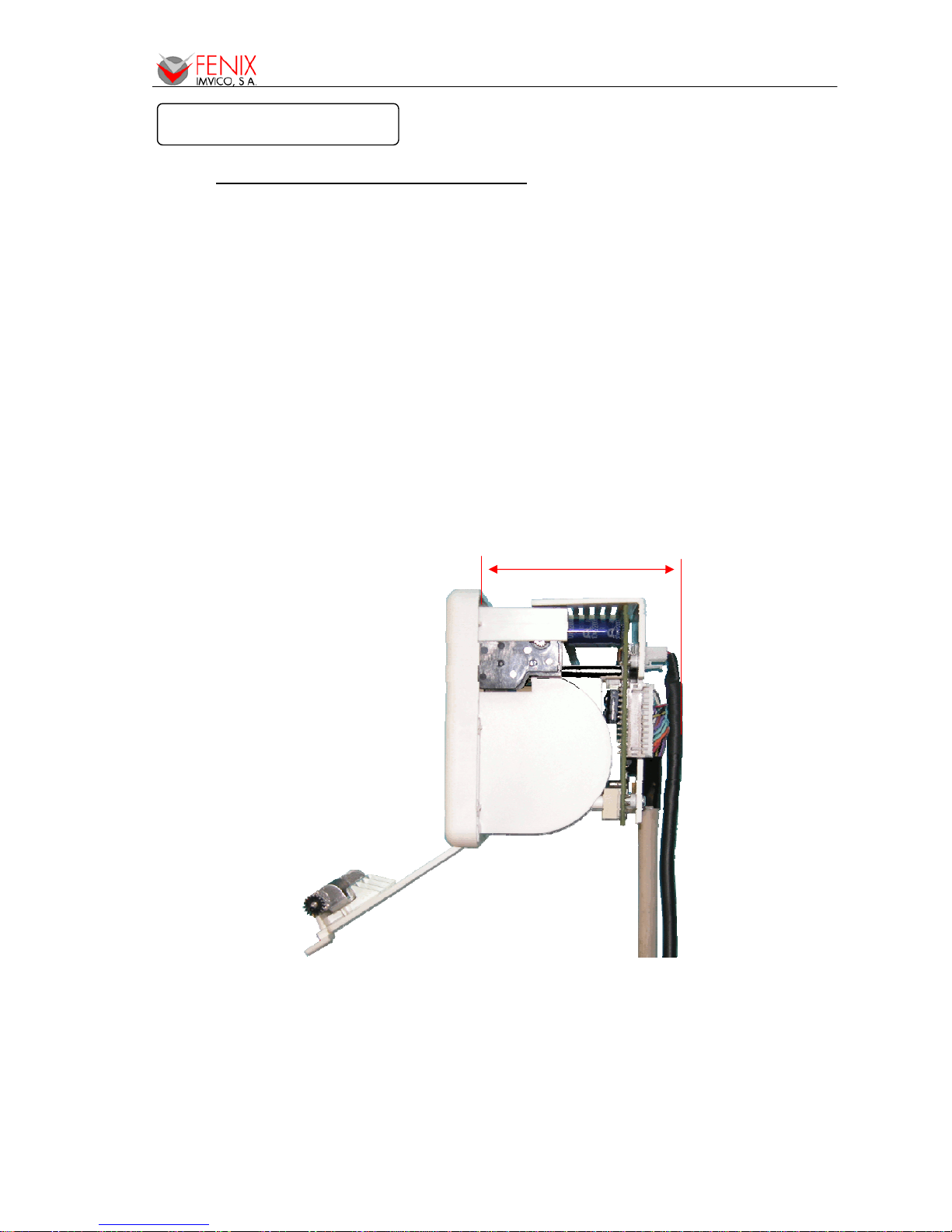
• Allow enough room in front of the printer in order to be able to open completely the door.
Minimum closet depth = 72mm
Fig. 2. - EPC1200 accessibility
This printer has been designed to ease the installation process and maintenance. Please follow
the recommendations below so there should not be any issue related to it.
4 – INSTALLATION
EPC1200 SERIES OPERATION MANUAL
10/56
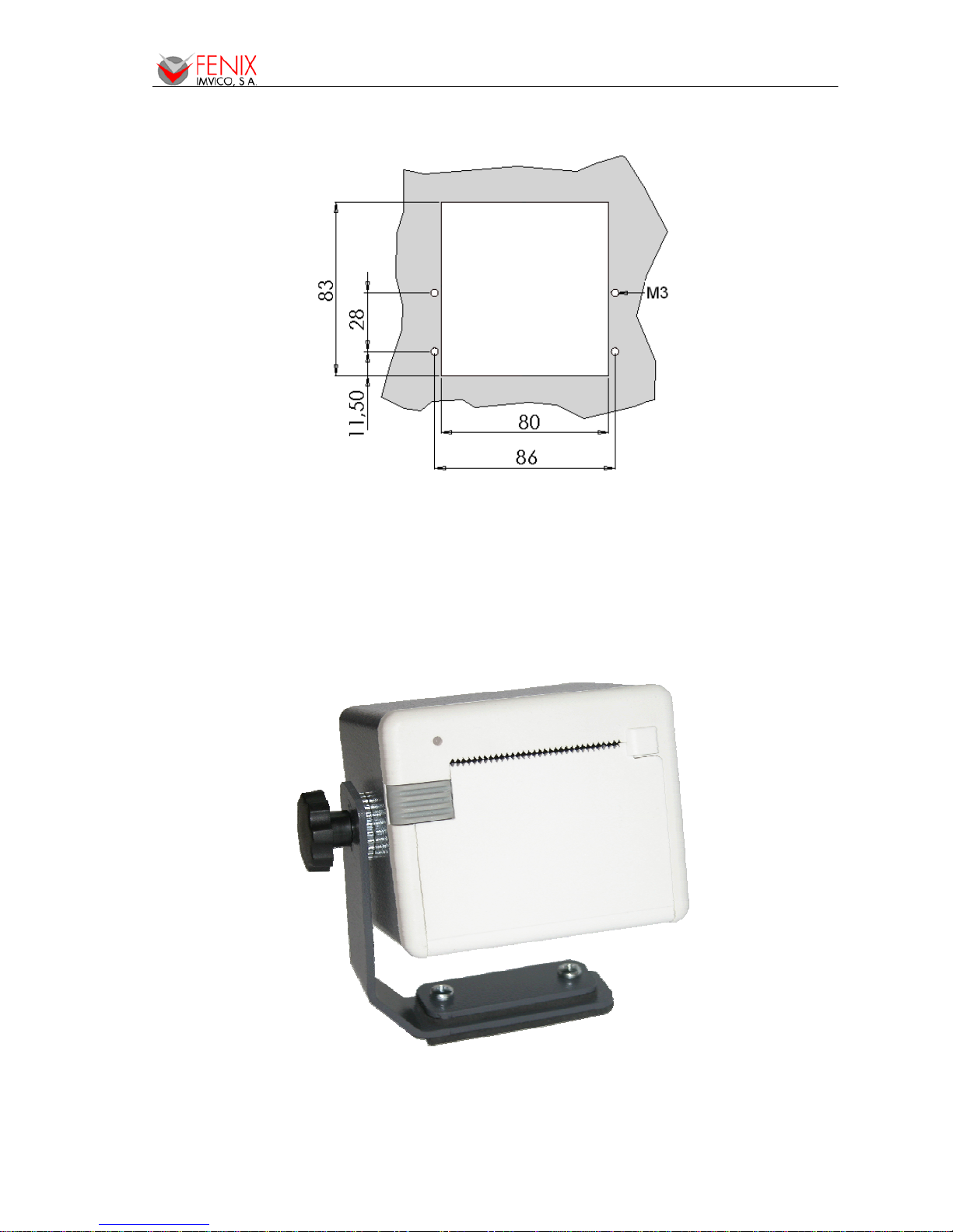
1) The printer must be set onto the user’s chassis and screwing it from outside. To do so cut a
window with the dimensions indicated on the figure and thread four holes as shown.
Fig. 3. - Fixing holes and window to be cut on the mounting wall
2) All the wiring has been designed to allow the user to firstly connect the cables and then screw
the printer onto the panel although the other way is also possible. If it is difficult to access the
rear side of the printer it is advisable to connect all the cables first and perform a self-test
before fixing the printer to the mounting wall.
Fig. 4. - Application of a self-stand PTR2 with the EPC1200.
EPC1200 SERIES OPERATION MANUAL
11/56
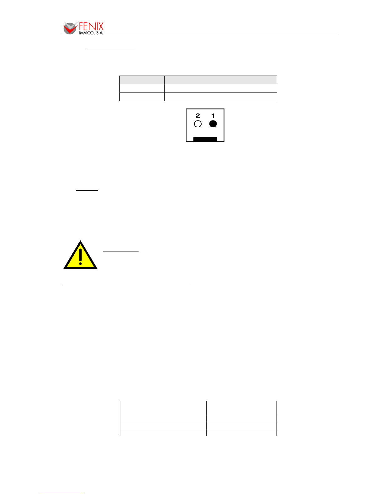
4.2- POWER SUPPLY
The EPC1200 is powered by an external power supply by means of a female 2-pin polarized
connector that includes a security anchor. The power supply voltage must be verified before powering
the printer.
Terminal nº Voltage
1 GNDP
2 VCC (5VDC or 12-24VDC)
Fig. 5. - Power supply connector CON1.
The power supply male connector must be a:
Housing: VHR-2N or VHR-2M (JST Ref.)
Terminal: SVH-21T-P1.1 or equivalent.
NOTES:
(1) If the number of dots that are energized at the same time is increased, a higher current
will flow; therefore, a power supply with an adequate current capability must be used.
(2) When designing lines and bit images, take the printing ratio and print duty into
consideration. Print quality may be poor if the printing ratio (energizing pulses/dot line) or
print duty is high.
(3) Average energizing pulse width is defined as 64 of 192 dots/dot line that are energized.
WARNING:
Beware not to invert the polarity of power supply. This may
irremediably damage the printer. Ensure that the voltage is the correct one. Use
the 2 terminals (2 wires) with 1 mm² minimum section each.
IMPORTANT NOTE ABOUT POWER SUPPLY:
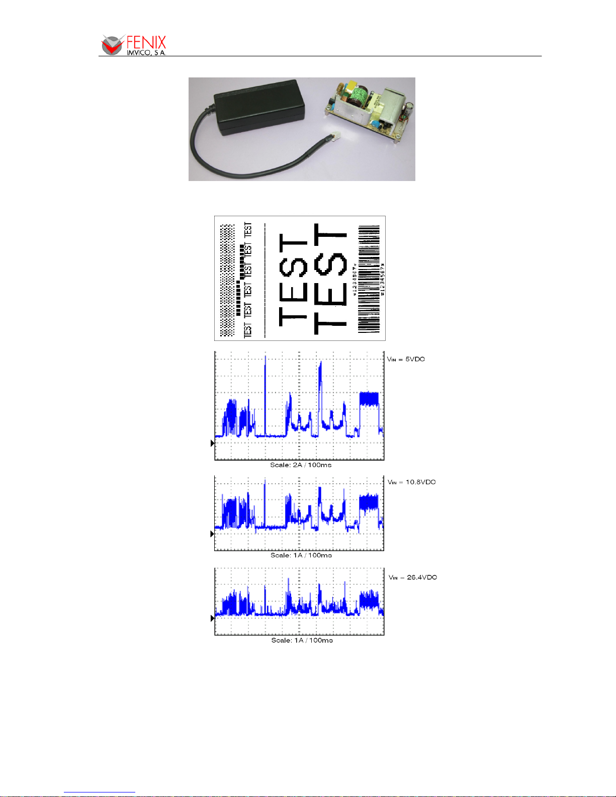
The current demand depends on the density of the printout. A 60W power supply covers all
adverse possibility (printing ratio of 100% black at any temperature). Anyway, power supply must meet
the peaks current that mechanism requires. As an example, next figure shows the relationship between
a sample ticket and the input current measured for 3 different voltage supplies. As it can be observed,
the peak current required when printing a horizontal line of about 90% density can be as high as 10A
when supplied at 5VDC.
A very important point to be aware of is the necessity of keeping the supply wiring the shortest
possible. When the printer is supplied with 5VDC, if the input voltage drops a significant quantity the
printer could stop working normally. The longest and thinnest the wire the higher the impedance and
therefore the voltage drop at the input.
FENIX offers different power supplies as an accessory option (See APPENDIX C – HOW TO
ORDER). These power supplies which have been exhaustively tested are available in OPEN FRAME or
ENCLOSED version.
Recommended power
supply
EPC1200-5 / EPC1250
5VDC / 60W
EPC1200-12 (12VDC supply)
12VDC / 60W
EPC1200-12 (24VDC supply)
24VDC / 60W
EPC1200 SERIES OPERATION MANUAL
12/56
Fig. 6. - FENIX supplied 5VDC power modules.
Fig. 7. - Current consumption example
EPC1200 SERIES OPERATION MANUAL
13/56
4.3- RS-232 SERIAL INTERFACE
4.3.1- RS-232 Serial interface specifications
• Data transmission type: Serial
• Synchronization: Asynchronous
• Flow control: DTR/DSR control
• Signal levels (RS232): MARK = -3 to -15 V Logic ‘1’/OFF
SPACE = +3 to +15 V Logic ‘0’/ON
• Speed: 9600, 19200, 38400, 115200 bps (bps: bits per second)
• Data length: 8 bits
• Parity: none, even, odd
• Stop bits: Fixed to 1
• Connector (user side): JST PHDR-18VS (housing)
JST SPHD-001T-P0.5 (terminal) or similar.
NOTE: Speed and parity depend on the settings (refer to section 4.6.2).
4.3.2- Change between online and offline mode
The printer is in offline mode:
1) When powering up or resetting the printer, until the printer is ready to receive data.
2) When the platen is opened.
3) After pressing the button while the paper advances.
4) When ‘out of paper’ causes the printer to stop printing.
5) When the power supply has a temporal abnormal voltage change.
6) When an error has occurred.
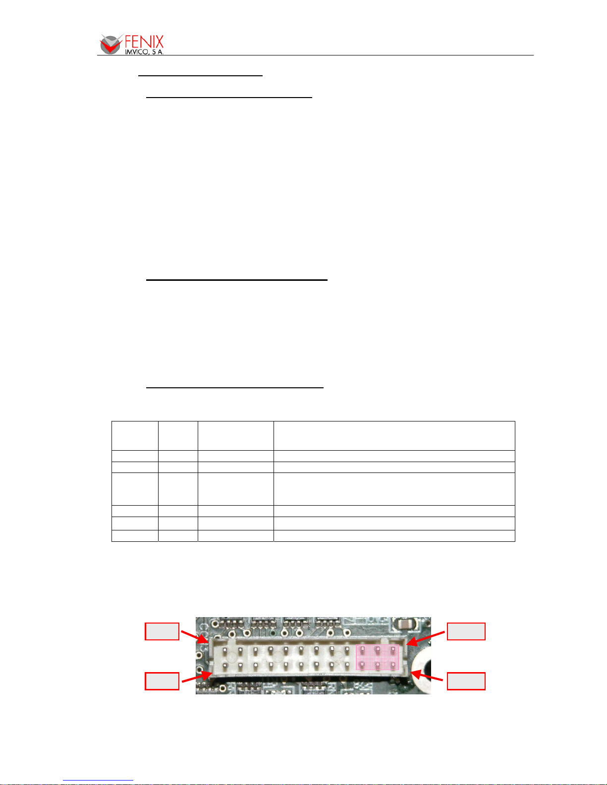
4.3.3- Serial RS-232 interface pins assignment
The assignments of the terminals of the RS-232 connector and the functions of its signals are
described in the following table:
Pin
Number
Signal
name
Signal direction
(from the printer
point of view)
Function
20 TXD Output Data transmission line.
21 RXD Input Data reception line.
22 RTS Output This signal indicates whether the printer is busy.
SPACE indicates that the printer is ready to receive
data, and MARK indicates that the printer is busy.
23 / 24 SG - Signal ground.
19 DTR Output This signal indicates whether an error occurs.
Other nc --- Not connected
Table 1. - Pins Assignments of RS-232 connector terminals
(*1) Definition of ‘data receiving buffer full’: the state of the printer becomes ‘buffer full’ when the
receiving buffer increases to 10 Kbytes maximum.
Note: The printer ignores the received data when the free space in the receiving buffer is 0 bytes.
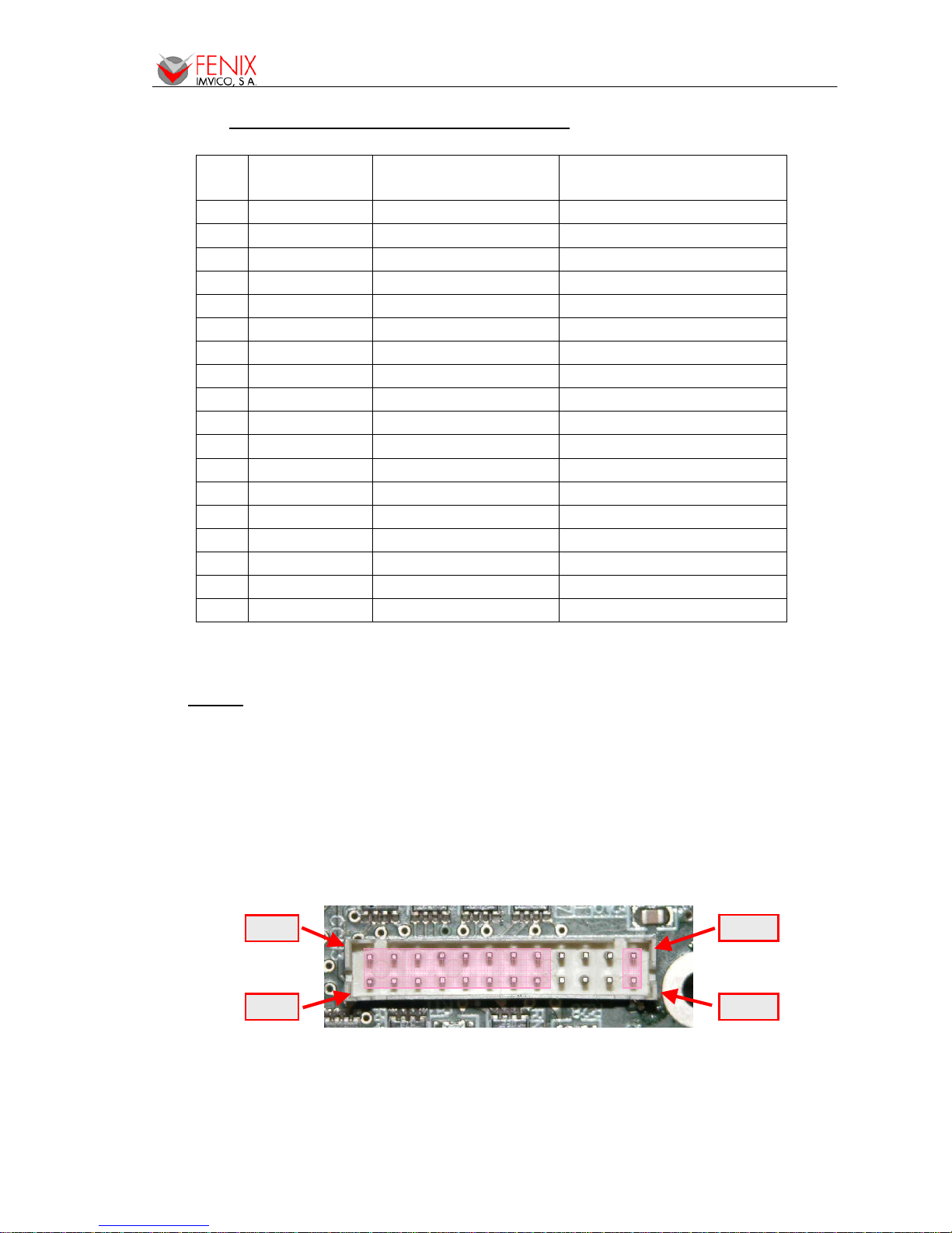
Fig. 8. - Serial RS-232 interface pins
Pin #1
Pin #2
Pin #23
Pin #24
EPC1200 SERIES OPERATION MANUAL
14/56
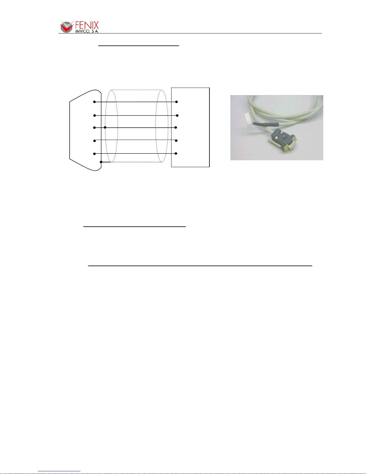
4.3.4- PC serial interface connection
Communications cable Ref. RS-232-6
Fig. 9. - PC serial cable
NOTES:
• Same configuration in the printer and in the host system should be set.
• The communication protocol should be set properly so that the transmitted data can be
received without errors.
4.4- CENTRONICS PARALLEL INTERFACE
The EPC1200 complies the IEE1284 protocol (NIBBLE MODE).
Copyright © 1994 by the Institute of Electrical and Electronic Engineers, Inc.
4.4.1- Compatibility mode (Data transmission from host to printer: Centronics compatible)
*Any system sending data to the printer (PC, PLC, custom board, etcetera) is considered to be a
host system.
The compatibility mode supports compatibility with the Centronics parallel interface.
a) Specifications
• Data transmission: 8-bit parallel
• Synchronization: nSTB signal externally provided
• Protocol: nACK (acknowledge) and BUSY signals
• Signal levels: TTL compatible
• Connector (user side): JST PHDR-18VS (housing)
JST SPHD-001T-P0.5 (terminal) or an equivalent model.
b) Switching between online and offline mode
The printer does not provide any switch for online/offline mode. The printer is in offline mode in
the following cases:
1) When powering ON or until the printer becomes ready for data transmission after it is
initialized by the reset signal from the interface
.
2) During the self-test.
3) When the platen is opened.
4) During paper advance using the paper advance button (paper feed).
5) When the printer stops printing due to ‘out of paper’.
6) When a temporal voltage abnormality happens to the power supply.
7) When an error occurs.
HOST EPC1200
FEMALE DB9 Housing: PHDR-24VS (JST)
Contact: SPHD-001T-P0.5
shield to chassis
2
3
5
6
8
20
21
23/24
19
22
TXD
RXD
GND
DTR
RTS
RXD
TXD
GND
DSR
CTS
EPC1200 SERIES OPERATION MANUAL
15/56
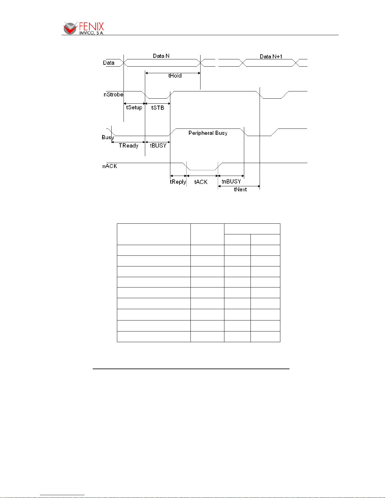
c) Timing diagram of data reception
Fig. 10. - Timing diagram of data reception
Description Symbol
Specification
Min(ns) Max(ns)
Data hold time tHold 750 --
Data setup time tSetup 750 --
STROBE pulse width tSTB 750 --
READY cycle idle time tReady 0 --
BUSY output delay time tBUSY 0 500
Data processing time tReply 0
∞
ACKNLG pulse width tACK 500
10
μ
s
BUSY release time tnBUSY 0
∞
ACK cycle idle time tNext 0 --
Table 2. - Timing of parallel communication protocol
4.4.2- Reverse mode (Data transmission from the printer to the host system)
The transmission of the printer status to the host system is implemented according to the
IEEE1284 standard (NIBBLE MODE).
EPC1200 SERIES OPERATION MANUAL
16/56
4.4.3- Parallel interface pins assignment for each mode
Pin Source Compatibility mode Nibble mode
1 Host Sys. nStrobe HostClk
2 Host Sys/printer Data0 (LSB) Data0 (LSB)
3 Host Sys/printer Data1 Data1
4 Host Sys/printer Data2 Data2
5 Host Sys/printer Data3 Data3
6 Host Sys/printer Data4 Data4
7 Host Sys/printer Data5 Data5
8 Host Sys/printer Data6 Data6
9 Printer Data7 (MSB) Data7 (MSB)
10 Printer nAck PrtClk
11 Printer Busy PrtBusy/Data3,7
12 Printer PError AckDataReq/Data2,6
13 Printer Selected Xflag/Data1,5
14 Host Sys. Nautofeed HostBusy
15 Printer nFault nDataAvail/Data0,4
16 Host Sys. nInit NInit
17 Host Sys. nSelectIn 1284-Active
18-25 GND GND
Table 3. - PC parallel connector (DB25)
NOTES:
1) The ‘n’ prefix used before a signal name means that they are active in ‘0’ logic level. If the host
system does not provide any of the signal lines mentioned above, both communication types
could fail.
2) It is recommended to use twisted pair cables (signal/ground), with the return sides connected to
the system signal ground level.
3) Do not ignore the nACK and BUSY signals during data transmissions. An attempt to transmit
data without nACK or BUSY control signals might cause lost data.
4) The interface cables should have the minimum required possible length (maximum
recommended length: 2 m).
Fig. 11. - Parallel interface pins
Pin #1
Pin #2
Pin #23
Pin #24

EPC1200 SERIES OPERATION MANUAL
17/56
4.4.4- PC parallel interface connection
Communications cable Ref. CENTRONICS-7
Fig. 12. - PC parallel cable
NOTES:
1) Same configuration in the printer and in the host system should be set.
2) Communication protocol should be set properly so that the transmitted data can be received
without errors.
3) The ‘n’ prefix used before a signal name means that they are active in ‘0’ logic level. If the host
system does not provide any of the signal lines mentioned above, both communication types
could fail.
4) It is recommended to use twisted pair cables (signal/ground), with the return sides connected to
the system signal ground level.
5) Do not ignore the nACK and BUSY signals during data transmissions. An attempt to transmit
data without nACK or BUSY control signals might cause lost data.
6) The interface cables should have the minimum required possible length (maximum
recommended length: 2 m).
4.5- USB INTERFACE
The EPC1200 USB interface has the following general features:
• USB specification USB 1.1 (12MHz full speed)
• Transfer type Bulk
• Maximum receive/transmit endpoint size 64 bytes
• Current consumption from USB bus 2mA max.
Shield to chassis
1
2
3
4
5
6
7
8
9
10
11
12
14
18
13
17
16
23/24
1
2
3
4
5
6
7
8
9
10
11
12
13
14
15
16
17
18/25
STB
D0
D1
D2
D3
D4
D5
D6
D7
BUSY
ACK
PE
ERR
GND
SELECTIN
AUTOFEED
SELECT
INIT
HOST EPC1200
MALE DB25 Housing:PHDR-24VS (JST)
Contact: SPHD-001T-P0.5
 Loading...