

Page 1
CONTROLLOREMOTO
I
REMOTECONTROL
CONTROLEADISTANCE
FERNSTEUERUNGEN
CONTROLEREMOTO
UK
F
D
E
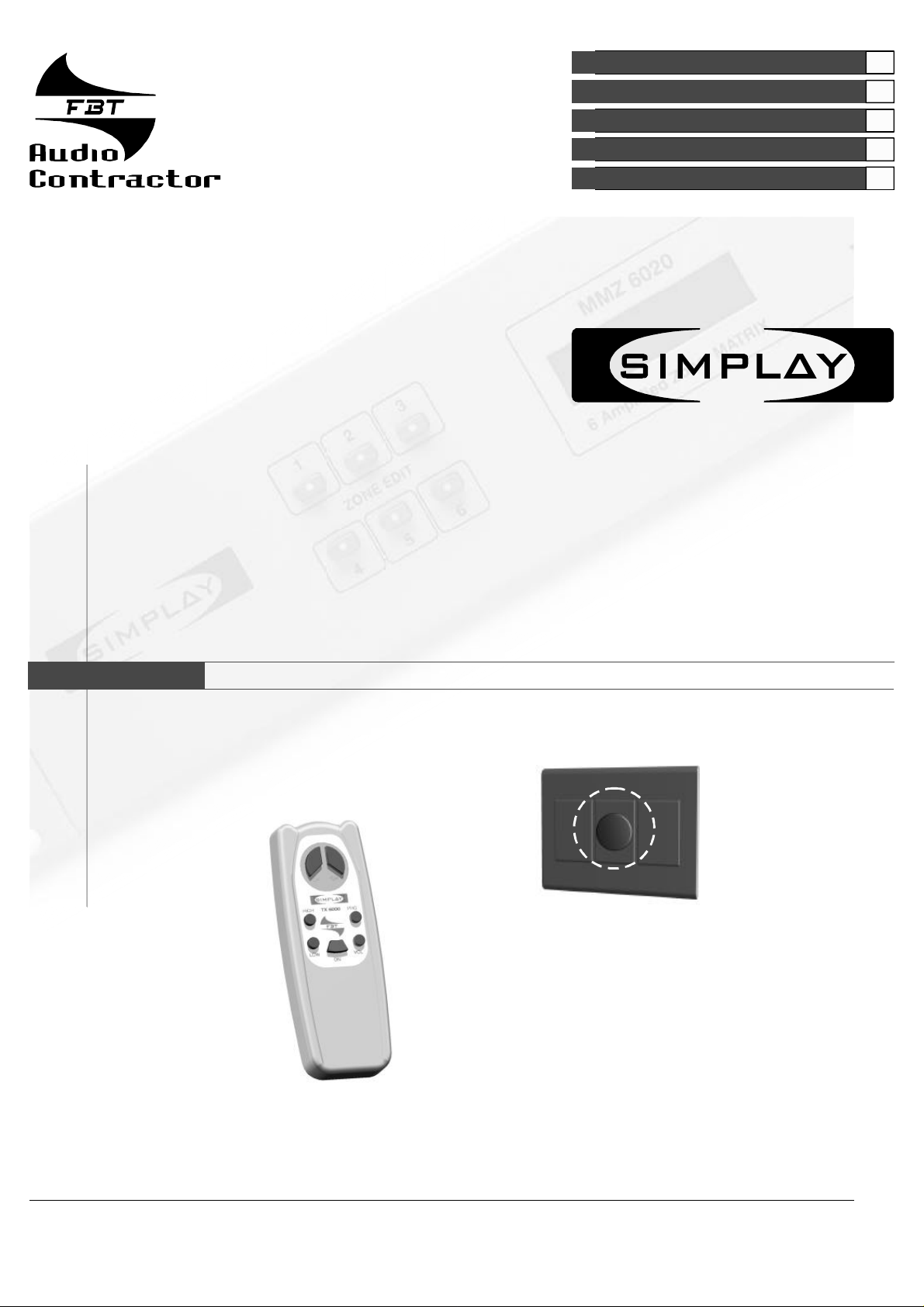
TRC6000
Kit
FBTELETTRONICAS.p.A.-ZONAIND.LESQUARTABUE-62019RECANATI(MC)-ITALY
TEL.071750591r.a.-FAX0717505920-P.O.BOX104-E-mail:info@fbt.it-www.fbt.it
Page 2
CONTROLLIREMOTI
TRC6000
KitcompostodauntrasmettitoremodelloTX6000(telecomandoinfrarossi)eun
ricevitoreinfrarossimodelloRX6000.
Iltrasmettitoredizonapermettediregolareilvolume,itoniacutiebassi,
#
accendere/spegnerel’audio,scegliereiltipodiingresso(tape,tuner,ecc).
Ilricevitoreècollegatoallamatriceconuncavettotelefonicoa4conduttori
#
(massimalunghezza500mt.)cheterminaconunconnettoreRJ-45(pin
1,2,3,4).
IMPORTANTE:
Ladistanzamassimadifunzionamentotrailricevitore/trasmettitoreèdi20mt
(senzaostacolitraloro).
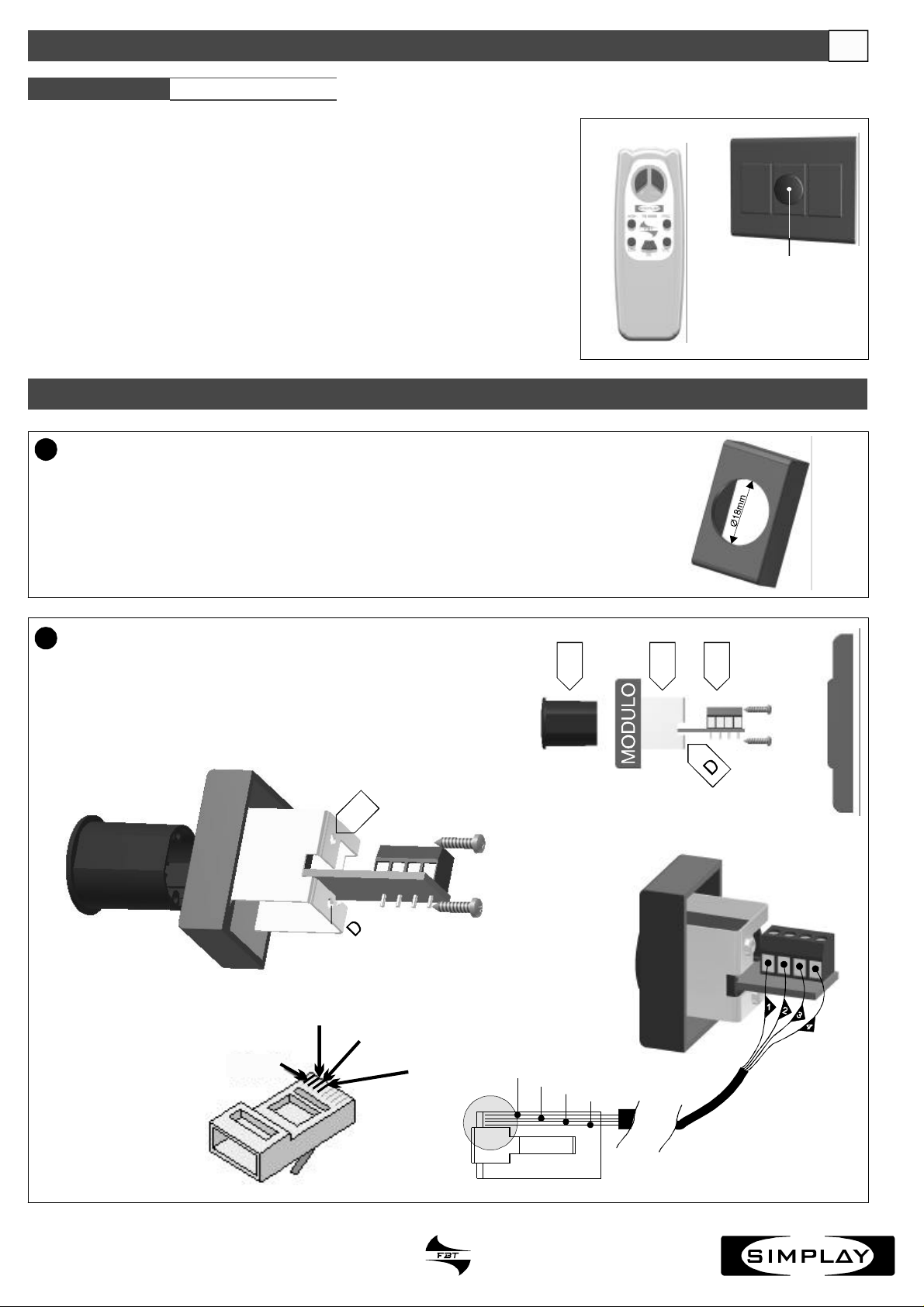
INSTALLAZIONE
1
Utilizzarecomesupporto1modulopercomuniscatole“portafrutti”usatenegli
impiantielettriciepraticareunforo(Ø18mm)alcentroutilizzandountrapano.
I
RX6000
TX6000
Inserirenelseguenteordine:
2
1)laguarnizionecilindrica(A)nelmodulo
2)ilcircuitostampato(B)nellaguarnizionecilindrica
3)ilfermoinalluminio(C),fissandolotramiteleappositevitinei
fori(D)
D
Pin2
Pin3
Pin1
Pin4
Pin1
A BC
Pin2
Pin3
Pin4
CODE:31144
RJ45
Page 3

UK
CODE:31144
REMOTECONTROLS
TRC6000
KitincludingaTX6000transmitter(IRremotecontrol)andaRX6000IR
receiver.
#Thezonetransmitterallowstoadjust:volume,highandlowtones,power
on/offandinputselection(tape,tuner,etc.)
#Thereceiverisconnectedtothematrixthrougha4-conductortelephone
cable(max.length500m)endingwithanRJ-45connector(PIN1,2,3,4).
IMPORTANTNOTICE:
Themaximumoperationdistancebetweenthetransmitterandthereceiveris
20mt(withoutobstaclesbetweenthem).
INSTALLATION
1
Forthesupportuseacommonmoduleforflushmountingjunctionboxesas
thoseusedforelectricinstallationsanddrillahole(Ø18mm)inthemiddleby
usingadrillingmachine.
Insertthefollowingcomponentsasintheorderbelow:
2
1)thecylindricalsealing(A)inthemodule
2)theprintedcircuit(B)intothecylindricalsealing
3)thealuminiumretainer(C)intherelatedholes(D)byfixingit
withtheappropriatescrews
RX6000
TX6000
A BC
Pin1
Pin2
D
Pin3
Pin4
Pin1
Pin2
RJ45
Pin3
Pin4
Page 4

CONTROLESADISTANCE
CODE:31144
TRC6000
Kitcomposéd'untransmetteurmodèleTX6000(télécommandeàinfrarouges)et
d'unrécepteuràinfrarougesmodèleRX6000.
#Letransmetteurdezonepermetderéglerlevolume,lestonalitésaigueset
basses,allumer/éteindrel'audio,choisirletyped'entrée(,etc.).
#Lerécepteurestbranchéàlamatriceparunpetitcâbletéléphoniqueà4
conducteurs(longueurmaximalede500m.)quitermineavecunconnecteurRJ45(broches1,2,3,4).
IMPORTANT:
Ladistancemaximaledefonctionnemententrelerécepteur/transmetteurestde
20m.(sansobstaclesentreeux).
tape,tuner
INSTALLATION
1
Utilisercommesupport,1modulepourdesboîtes«porte-fruits»communes
utiliséesdanslesinstallationsélectriquesetfaireuntrou(Ø18mm)aucentreen
utilisantuneperceuse.
F
RX6000
TX6000
Introduireselonl'ordresuivant:
2
1)lagarniturecylindrique(A)danslemodule
2)lecircuitimprimé(B)danslagarniturecylindrique
3)l'arrêtoirenaluminium(C),enlefixantaveclesvisspéciales
danslestrous(D).
D
Pin2
Pin3
Pin1
Pin4
Pin1
A BC
Pin2
Pin3
Pin4
RJ45
Page 5

D
CODE:31144
FERNSTEUERUNGEN
TRC6000
SatzbestehendauseinemSenderModellTX6000(IR-Fernbedienung)und
einemIR-EmpfängerModellRX6000.
#DerZonen-SenderermöglichteinRegulierenderLautstärke,derhohenundder
niedrigenTöne,dasEin-undAusschaltendesAudiosunddieWahldesEingangs
(Tape,Tunerusw.).
#DerEmpfängeristübereinTelefonkabelmit4SteckverbindernandieMatrix
angeschlossen(Längemax.500m),dasmitdemAnschlusssteckerRJ-45(PIN
1,2,3,4)endet.
WICHTIG:
DermaximaleAbstand,indemEmpfängerundSenderfunktionieren,beträgt20m
(ohneHindernissedazwischen).
INSTALLATION
1
AlsTräger1Modulfürnormale„Obst“-Kästenbenutzen,dieinelektrischen
Anlagenverwendetwerden,undinderMittemiteinemBohrereinLoch(Ø18mm)
bohren.
RX6000
TX6000
InderfolgendenReihenfolgeeinfügen:
2
1)diezylinderförmigeDichtung(A)indasModul
2)dieLeiterplatte(B)indiezylinderförmigeDichtung
3)denFeststellerausAluminium(C),dermitdenentsprechenden
SchraubenindenLöchern(D)befestigtwerdenmuss.
D
Pin2
Pin3
Pin1
Pin4
Pin1
A BC
Pin2
Pin3
Pin4
RJ45
Page 6

CONTROLESREMOTOS
CODE:31144
TRC6000
ElkitsecomponedeuntransmisormodeloTX6000(mandoainfrarrojos)yun
receptorainfrarrojosmodeloRX6000.
#Eltransmisordezonapermiteajustarelvolumen,lostonosagudosygraves,
encender/apagarelaudio,elegireltipodeentrada(tape,tune,ecc.).
#Elreceptorseconectaalamatrizconuncabledeteléfonode4interruptores
(longitudmáximade500mt)queterminaconunconectorRJ-45(pin1,2,3,4).
E
IMPORTANTE:
Ladistanciamáximadefuncionamientoentreelreceptor/transmisoresde20
metros(sinobstáculoentrelosdosdispositivos).
INSTALACIÓN
1
Utilizarcomosoporte1móduloparacajaseléctricascomunesutilizadasen
instalacioneseléctricasyhacerunagujero(Ø18mm)enelcentroutilizandoun
taladro.
Insertarlassiguientespiezasrespetandoelorden:
2
1)lagomacilíndrica(A)enelmódulo
2)elcircuitoimpreso(B)enlagomacilíndrica
3)eltopecilíndrico(C)yfijarloconlostornillosenlosagujeros(D)
RX6000
TX6000
A BC
Pin1
Pin2
D
Pin3
Pin4
Pin1
Pin2
RJ45
Pin3
Pin4
 Loading...