

Page 1
UNITÀDIPOTENZAMULTICANALE
I
FOURCHANNELSPOWERUNIT
AMP2AMP1 OC FAULT AMP4AMP3 OC FAULT
FOURCHANNELSPOWERUNIT
MULTICHANNELPOWERUNIT
UNITÉDEPUISSANCEMULTICANALE
MEHRKANAL-LEISTUNGSEINHEITEN
UNIDADDEPOTENCIAMULTICANAL
MPU4240
AMPLIFIER3/4AMPLIFIER1/2 PWR
MPU4120
UK
F
D
E
AMPLIFIER1/2
AMP2AMP1 OC FAULT AMP4AMP3 OC FAULT
FOURCHANNELSPOWERUNIT
AMP2AMP1 OC FAULT AMP4AMP3 OC FAULT
TWOCHANNELSPOWERUNIT
AMPLIFIER1/2
AMP2AMP1 OC FAULT
AMPLIFIER3/4
AMPLIFIER3/4AMPLIFIER1/2 PWR
PWR
PWR
MPU4060
MPU2120
FBTELETTRONICAS.p.A.-ZONAIND.LESQUARTABUE-62019RECANATI(MC)-ITALY
TEL.071750591r.a.-FAX0717505920-P.O.BOX104-E-mail:info@fbt.it-www.fbt.it
Page 2
I
INDICE
INTRODUZIONE
Perottimizzareilrapportotrainvestimentieprestazioni,oggiinstallatorieutilizzatorifinali
chiedonoall’industriasistemisemprepiùcompletieversatili,ingradodirispondere,per
funzionietecnologia,allemoderneesigenzedidistribuzionesonora.
Unimpiantoprogettatoseguendoquesteindicazionideveaverepotenzasufficienteper
sonorizzarepiùaree,minimonumeropossibiledicomponenti,praticitàdiassemblaggio,
economicitàdiesercizio,prestazionielevateecostanti.
LaElettronicaS.p.A.,interpretandoeanticipandotalinecessità,harealizzatouna
FBT
nuovalineadiamplificatori:laseriechecomprendeimodelli,
MPU4120,MPU4240.
Sitrattadiunitàdipotenzamonobloccocondueoquattrofinali,uscitecontrasformatoridi
lineaa70Ve100Vchepossonolavorareinmodalitàstereoo“somma”con2possibili
configurazioniperciascunaunitàdipotenza.
Rispostainfrequenzada40Hza20kHz,filtrointernopassa-altoa40Hz,protezionetermica
ecortocircuiti;sulpannellofrontaleindicazioniluminosedellamodalitàdilavoroedella
presenzadiguasti,regolazionedeivolumisulpannelloposteriore.
MPUMPU2120MPU4060,
1
Page 3
ATTENZIONE
RISCHIODISHOCKELETTRICO
NONAPRIRE
I
!
!
PEREVITAREILRISCHIODISHOCKELETTRICO
NONUSAREUTENSILIMECCANICIALL'INTERNO
CONTATTAREUNCENTRODIASSISTENZAQUALIFICATO
PEREVITAREILRISCHIODIINCENDIOODISHOCKELETTRICO
NONESPORREL'APPARECCHIATURAALLAPIOGGIA
QUESTOSIMBOLOAVVERTE,LADDOVEAPPARE,LAPRESENZADIUNA
TENSIONEPERICOLOSANONISOLATAALL’INTERNO:
ILVOLTAGGIOPUÒESSERESUFFICIENTEPERCOSTITUIRE
ILRISCHIODISCOSSAELETTRICA.
QUESTOSIMBOLOAVVERTE,LADDOVEAPPARE,DELLA
PRESENZADIIMPORTANTIISTRUZIONIPERL’USOEPER
LAMANUTENZIONENELLADOCUMENTAZIONE
ALLEGATA.SIPREGADICONSULTAREILMANUALE.
NONAPRIREILCOPERCHIO
OALL'UMIDITA'
PRECAUZIONI
°Perconsentireunaventilazionesufficienteènecessariopredisporreunadistanza
minimadicirca30cm.pertuttiilatidell’apparecchiio.
°Laventilazionenondeveessereimpeditacoprendoleaperturediventilazionecon
oggettiqualigiornali,tovaglie,tende,ecc.
°Nessunasorgentedifiammanuda,qualicandeleaccese,deveessereposta
sull’apparecchio.
°L’apparecchionondeveessereespostoastillicidiooaspruzzid’acquaequindisopraal
dispositivonondevonoesserepostioggetticontenentiliquidi,comeades.vasi.
INSTALLAZIONE
°Qualoral’apparecchiovengainstallatoinuncontenitorerack,questodovràpossedere
tuttiirequisitiprevistidallanormativaEN60439-1,inparticolarelaparteposterioredeve
esserechiusamedianteappositopannello.
2
Page 4

I
1)Leggerequesteistruzioni
2)Conservarequesteistruzioni
3)Fareattenzioneatuttigliavvertimenti
4)Seguiretutteleistruzioni
5)Nonusarequestodispositivovicinoall’acqua
6)Puliresoloconunostrofinaccioasciutto
7)Nonostruireleaperturediventilazione.L’installazionedeveessereeseguitainbasealle
istruzionifornitedalproduttore.
8)Noninstallarenellevicinanzedifontidicalorecometermosifoni,valvolediregolazione,
stufeoaltriapparecchi(amplificatoricompresi)cheproduconocalore
9)Nonannullarel’obiettivodisicurezzadellespinepolarizzateoconmessaaterra.Le
spinepolarizzatehannoduelame,unapiùlargadell’altra.Unaspinaconmessaaterraha
duelameeunterzopoloditerra.Lalamalargaoilterzopoloservonoperlasicurezza
dell’utilizzatore.Selaspinafornitanonèadattaallapropriapresa,consultareunelettricista
perlasostituzionedellaspina.
10)Proteggereilcavodialimentazionedalcalpestioedallacompressione,inparticolarein
corrispondenzadispine,prolungheenelpuntodalqualeesconodall’unità.
11)Usaresolodispositiviopzionali/accessorispecificatidalproduttore.
12)Utilizzareesclusivamenteconcarrelli,supporti,treppiedi,mensoleo
tavolespecificatidalproduttoreovendutiunitamenteall’apparecchio.Sesi
utilizzauncarrelloprestareattenzionedurantelospostamentocombinatodel
carrelloedell’apparecchio,perevitareilverificarsididannidovutiad
eventualeribaltamento.
IMPORTANTIISTRUZIONIDISICUREZZA
13)Staccarelaspinaincasoditemporaleoquandononsiusal’apparecchioperunlungo
periodo.
14)Perl’assistenzatecnicarivolgersiapersonalequalificato.L’assistenzatecnicaè
necessarianelcasoincuil’unitàsiadanneggiata,peres.perproblemidelcavodi
alimentazioneodellaspina,rovesciamentodiliquidiodoggetticadutiall’interno
dell’apparecchio,esposizioneallapioggiaoall’umidità,anomaliedifunzionamentoo
cadutedell’apparecchio.
L’APPARECCHIODEVEESSERECOLLEGATOALLARETEELETTRICAMEDIANTEUNA
PRESACONUNCOLLEGAMENTOALLATERRADIPROTEZIONE.
Questoapparecchioèdotatodipresadialimentazione;installarel’apparatoinmanierache
lapresadelcavodialimentazionerisultifacilmenteaccessibile.
3
Page 5

COLLEGAMENTI
I
!
°Primadiutilizzarel’apparecchiaturaassicurarsichelatensioneapplicatasiacorretta.
Connetterel’amplificatoresoltantosupresedicorrenteconriferimentoamassa.
°Perevitarerischidiscossaelettricanontoccaremaifiliscoperticonnessiaimorsetti
dell’amplificatorequandoquestoèinfunzione.
°L’apparecchiodeveesserealimentatodallatensionediretesolodopoaverterminatotutti
icollegamenti.
°
LELINEEDIALIMENTAZIONEDEGLIALTOPARLANTIDEBBONOESSERE
REALIZZATECONCAVIINGUAINATI.
1)
LINEEABASSAIMPEDENZA
-L’impedenzaequivalentedeglialtoparlanticonnessideveessereugualeosuperiorea
quellaindicatasuimorsettidiuscitadell’amplificatore
2)LINEEATENSIONECOSTANTE
-Ognialtoparlantedeveessereprovvistoditrasformatoredilineaconunatensionedi
ingressougualeaquelladilinea(70,100V)
°Lasommadellepotenzedeglialtoparlantinondeveeccederelapotenzadiuscita
dell’amplificatore
4
Page 6

I
CABLAGGIODEGLIINGRESSI
COLLEGAMENTI
1)Pertuttiicollegamentid’ingressoutilizzaresolocavischermati.Icaviconschermaturaa
pellicolaoconintreccioadaltadensitàsonosuperiori.Icaviconschermaturaatrefoloa
spirale,perquantomoltoflessibili,sipossonodanneggiareconiltempoecausareproblemi
dirumore.
2)Evitare,sepossibile,l’impiegodilineesbilanciate;senonsihaaltrasceltamantenerei
caviquantopiùcortipossibile.
3)Primadicambiareiconnettorioicavid’ingressoruotareinposizioneminimaicontrollidel
livellodegliamplificatori(sensoantiorario).
4)Primadimodificareleconnessioniall’uscita,ruotarealminimoillivellodegliamplificatori
espegnerel’alimentazioneAC,perminimizzarelapossibilitàdicortocircuitisulleuscite.
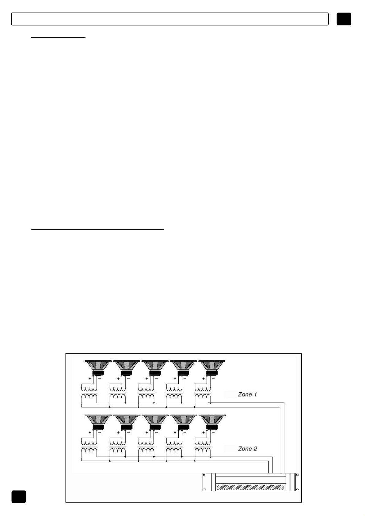
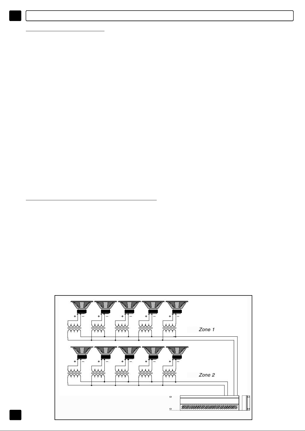
SISTEMIADIFFUSORIDISTRIBUITI
Isistemiadiffusoridistribuitiperpagingemusicasonomoltocomuniinrealtàcome
alberghi,ristoranti,uffici,scuole,ecc.Inquestisistemisvariatidiffusorisonodelocalizzatisu
tuttal’area.
Talesistemamultispeakerconsisteinunamplificatoreocanalediamplificazionechepilota
unoopiùspeakerdotatiditrasformatori.
Itrasformatoririduconolatensionedilineaadunlivellopiùbasso,taledapilotareidiffusori,
esonocollegatiacavallodellacoppiadiconduttori.Lacombinazionedeltrasformatoree
dellospeakerinlineapresentaunimpedenzamoltopiùaltaversol’amplificatore,rispettoal
casodidiffusoresingolo,cosacherendepossibileaggiungeremoltispeakersuunasingola
lineadisegnaleinpotenza.
100V
5
100V
AMPLIFICATORE
Page 7
CONTROLLIEFUNZIONI
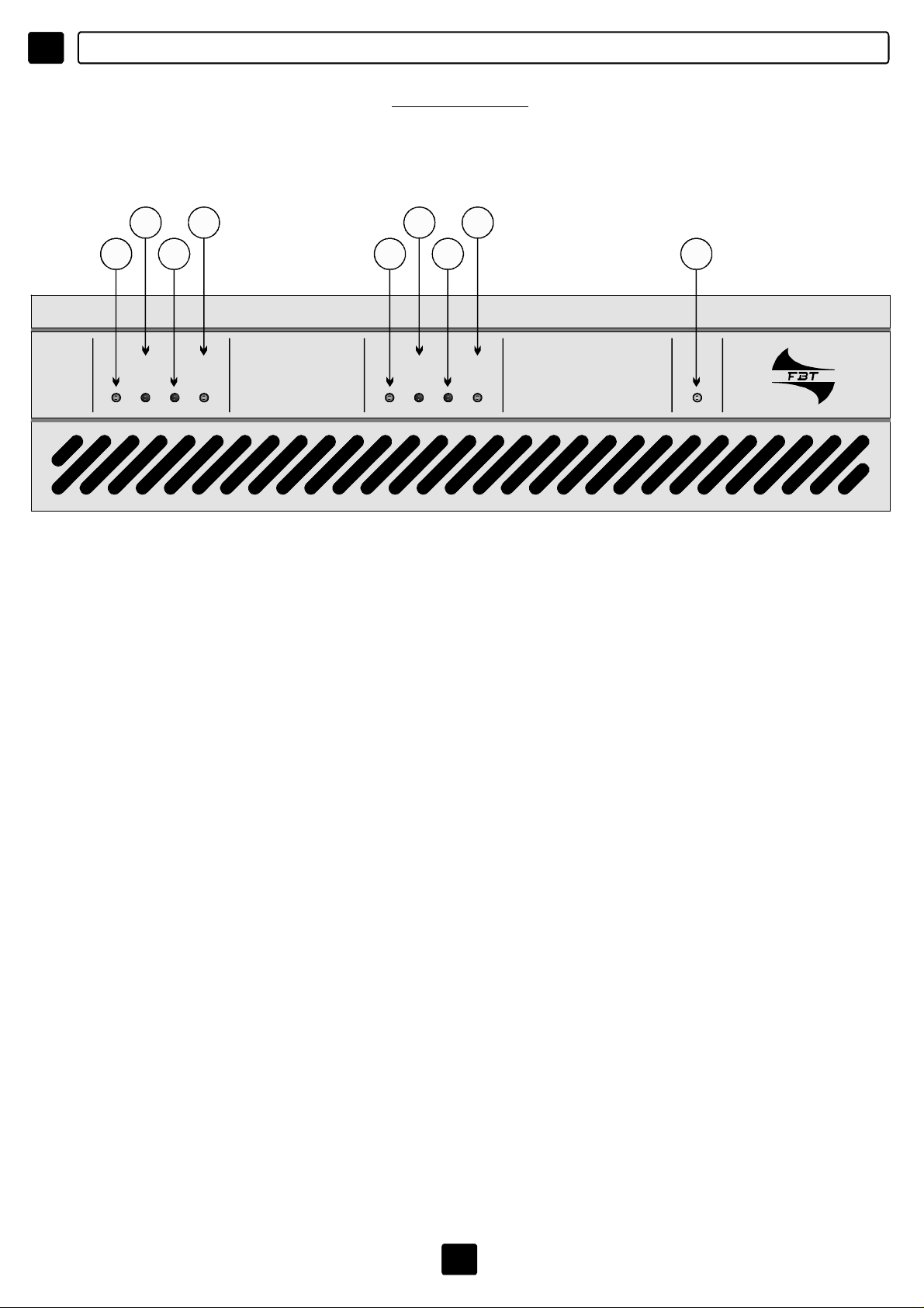
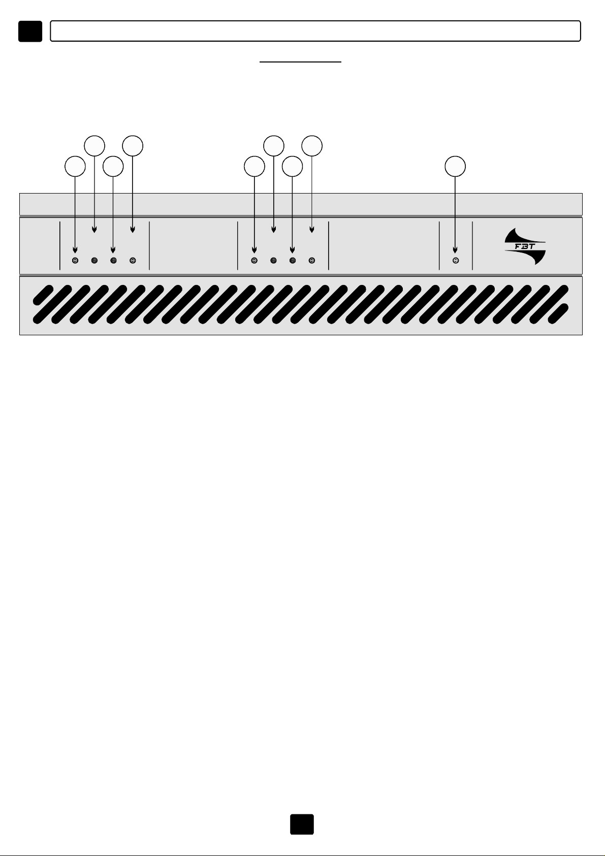
PANNELLOANTERIORE
MPU4240/MPU4120/MPU4060/MPU2120
I
2
1
4
3
AMP2AMP1 OC FAULT AMP4AMP3 OC FAULT
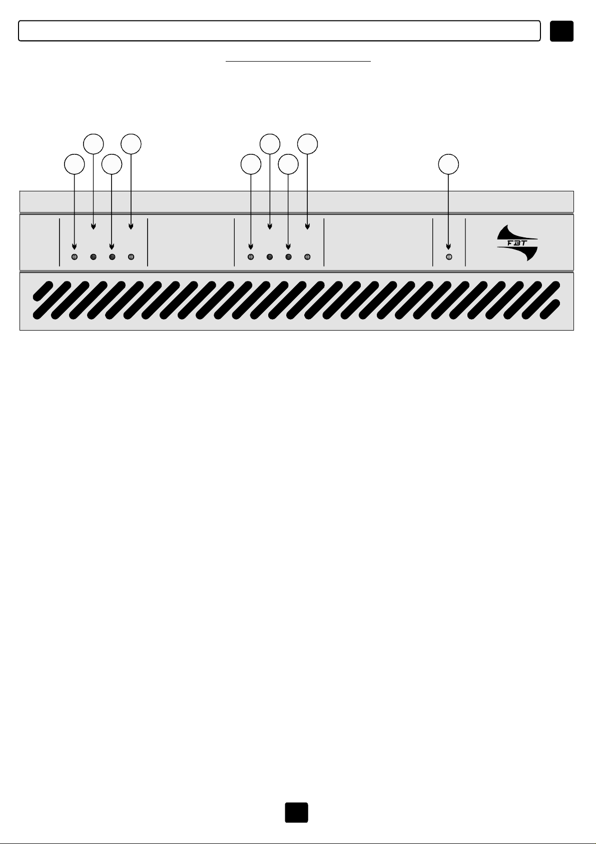
[1-4]AMP1/2/3/4:
corrispondente
2
1
AMPLIFIER3/4AMPLIFIER1/2 PWR
4
3
5
MPU4240FOURCHANNELSPOWERUNIT
L’accensionedelledindicalapresenzadelsegnalesull’amplificatore
[2]OC:
OVERCURRENT_l’accensionedelledindicachelacorrenteassorbitadaun
carico(equindilapotenza)stasuperandoquellachepuòesserefornitaesopportata
dall’amplificatoreoppuresièverificatouncortocircuitosullalinea.
[3]FAULT:
L’accensionedelledindicalarotturadiuncomponenteol’interventodella
protezionetermica:questopuòaccaderepereccessivocalore,persovraccaricooperun
segnaletroppoaltoafrequenzaaudioelevata.Intalicasi,perevitaredanniaicircuitidi
potenza,laprotezioneintervienesospendendomomentaneamentel’amplificazione,finoal
ripristinodellecondizioniottimali.
[5]PWR
:Indical’accensionedelsistema.
6
Page 8
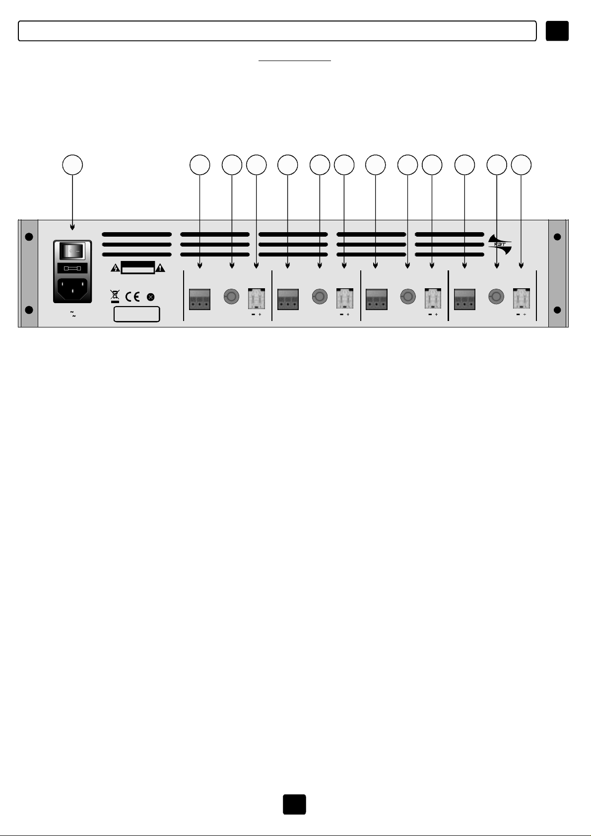
CONTROLLIEFUNZIONI
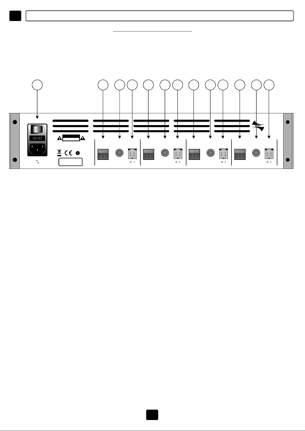
PANNELLOPOSTERIORE
MPU4240/MPU4120/MPU4060/MPU2120
6 7 8 9 7 8 9 7 8 9 7 8 9
MPU4060
CAUTION
RISKOFELECTRICSHOCK
DONOTOPEN
TOREDUCETHERISKOFELECTRICSHOCKDONOT
REMOVECOVER(ORBACK)NOUSERSERVICEABLE
PARTSINSIDEREFERSERVICINGTOQUALIFIED
SERVICEPERSONNEL
AMPLIFIER1AMPLIFIER4 AMPLIFIER3 AMPLIFIER2
85÷132Vac/T3,15A-250V
170÷264Vac/T1,6A-250V
PowerConsumption250VA
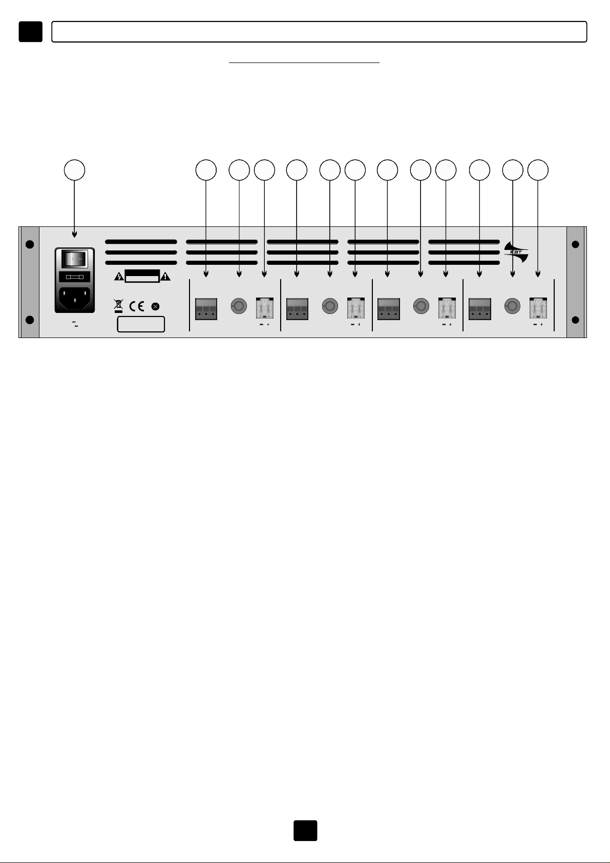
[6]ALIMENTAZIONE
MadeinItaly
H C S
VOLUME OUTINPUT
H C S
VOLUME OUTINPUT
H C S
VOLUME OUTINPUT
:Presaperilcollegamentoallareteelettrica,interruttoredi
H C S
VOLUME OUTINPUT
accensionedelsistemaealloggiamentodelfusibilediprotezionedelcircuitodi
alimentazione.Incasodirotturadelfusibile,quest’ultimovasostituitosolodafusibilicon
ugualicaratteristicheelettriche.
Permodificareilvaloredellatensionedialimentazione
vedipag.12
[7]INPUT:
Connettoriatrepinconbloccaggioavite,permettonodicollegareisegnalidi
ingressodegliamplificatori1/2/3/4.
Utilizzaresolocavischermatievitandol’impiegodilineesbilanciate(incasocontrario
mantenereicavipiùcortipossibile).
Primadicambiareiconnettorioicavidiingressoruotarenellaposizioneminimaicontrollidi
livellodegliamplificatori.
[8]VOLUME:
Regolazionedellivellodiuscitadegliamplificatori.
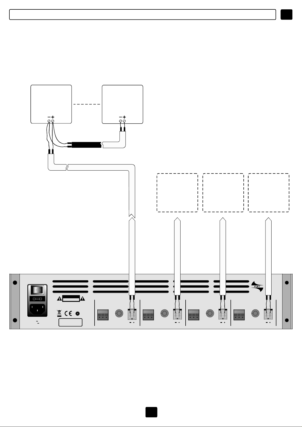
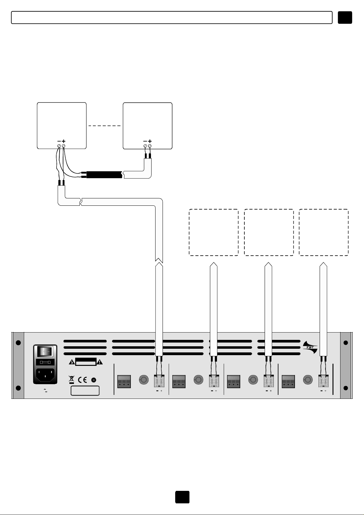
[9]OUT :Connettoridiuscitaaduefastonperilcollegamentodidiffusoricontrasformatore
dilineaa100V/70V.Sonopossibiliconfigurazioniinmodalitàstereoosomma
(vedipagg.8-9-10-11)
7I7
Page 9
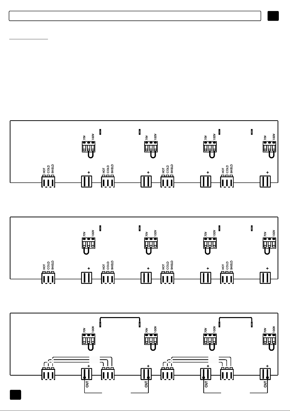
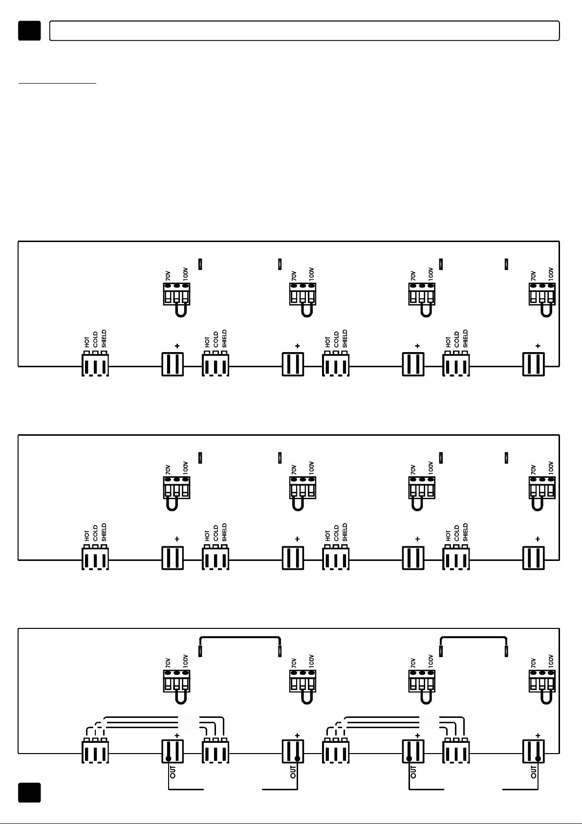
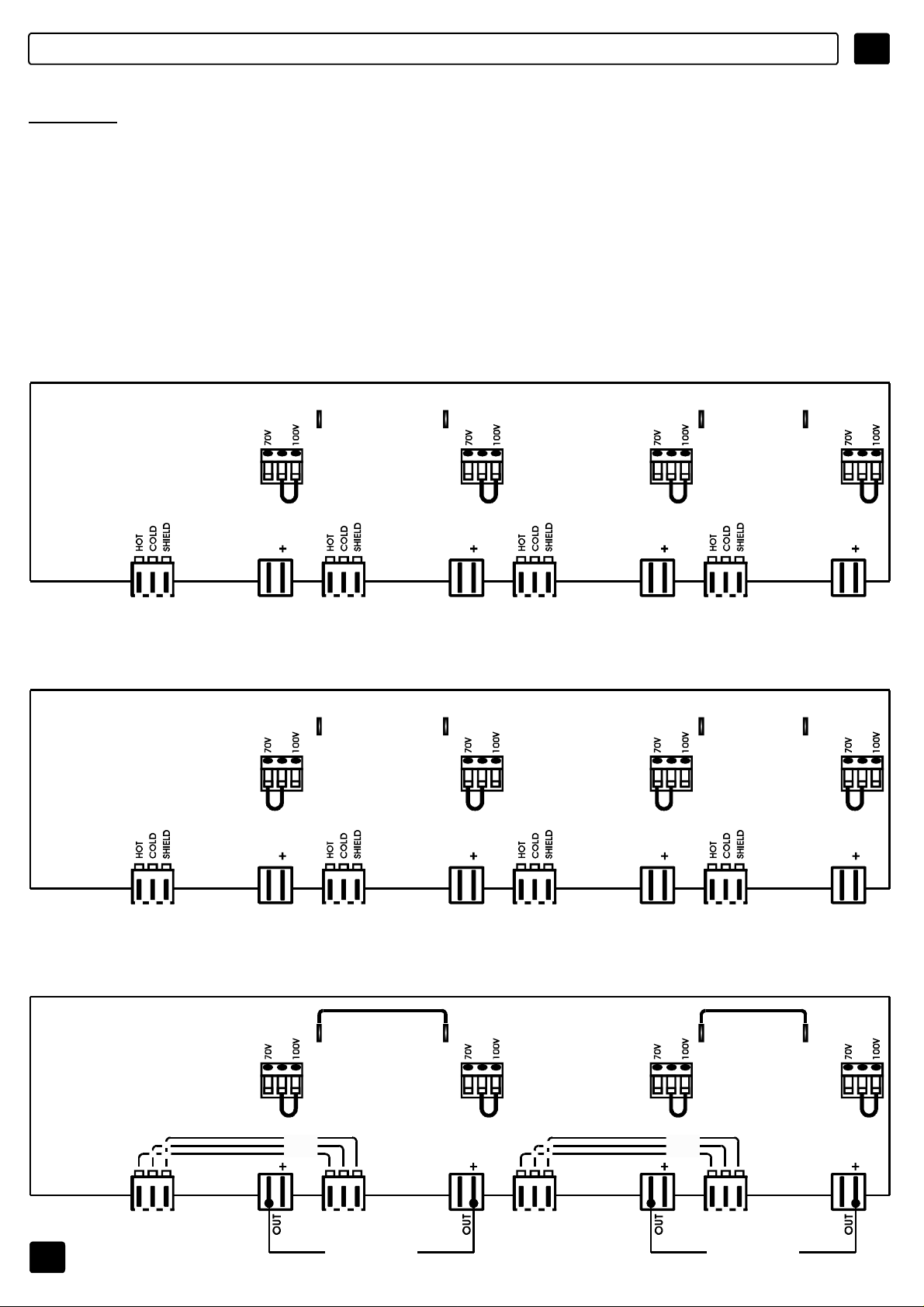
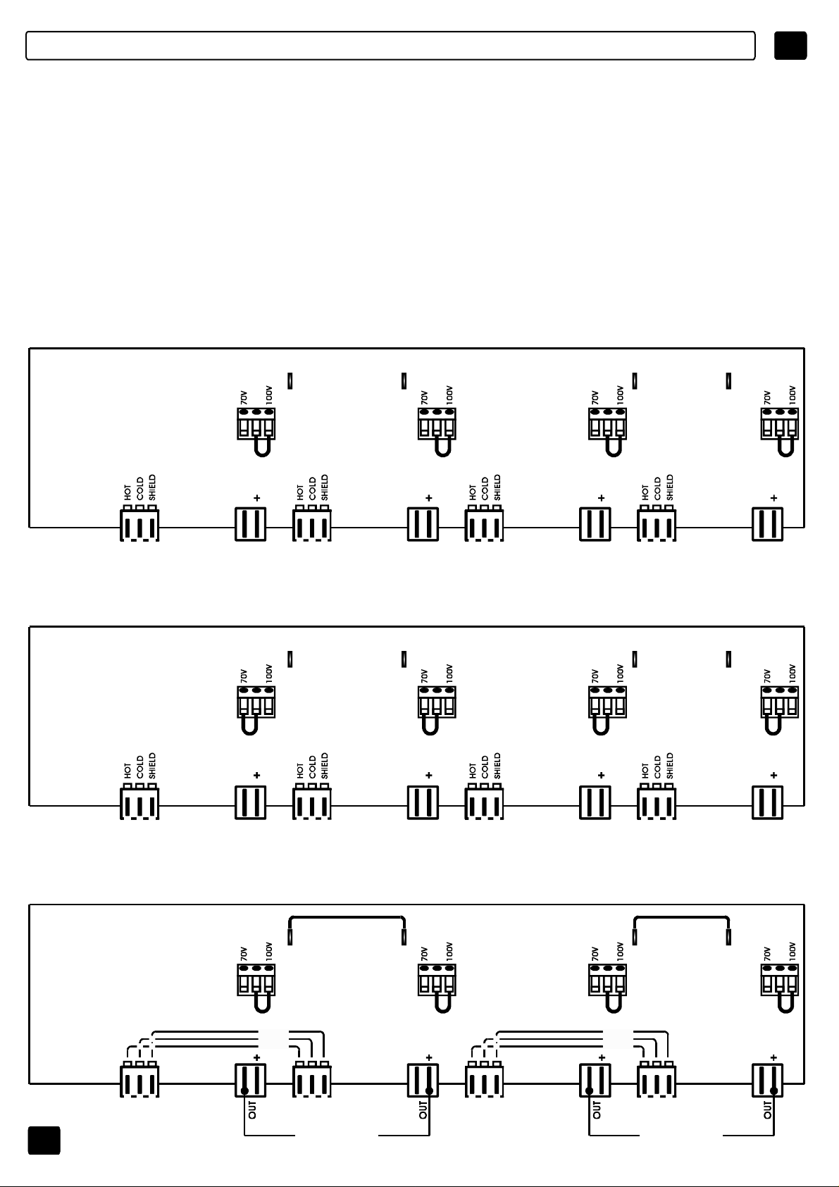
MODODIUTILIZZO
I
ATTENZIONE
ILCONNETTOREDIUSCITAÈSTATOCOLLEGATOSU100V/42ohm.PEROTTENERELE
ALTREUSCITEA70VSEGUIRELOSCHEMARIPORTATOSULCOPERCHIO
DELL’APPARECCHIATURA.PERACCEDEREALCONNETTORERIMUOVEREILCOPERCHIO.
PREDISPOSIZIONEINTERNA,ACCESSIBILERIMUOVENDOLAPARTESUPERIORE
DELL’APPARECCHIO,CHEPERMETTELACONFIGURAZIONEDELLEUNITÀDIPOTENZA
COMEDADISEGNO.
MODODIUTILIZZODELL’UNITÀMPU4240
4x240W
USCITAA100V
FS1 FS2 FS3 FS4
M1 M2 M3 M4
4x240W
USCITAA70V
0 0 0 0
J1 J16 J6 J17 J9 J18 J12 J19
INPUT INPUT INPUT INPUTOUT OUT OUT OUT
SPEAKERS
100V/240W
O
42OHMMIN.
FS1 FS2 FS3 FS4
M1 M2 M3 M4
0 0 0 0
J1 J16 J6 J17 J9 J18 J12 J19
INPUT INPUT INPUT INPUTOUT OUT OUT OUT
SPEAKERS
70V/240W
O
21OHMMIN.
SPEAKERS
100V/240W
O
42OHMMIN.
SPEAKERS
70V/240W
O
21OHMMIN.
SPEAKERS
100V/240W
O
42OHMMIN.
SPEAKERS
70V/240W
O
21OHMMIN.
SPEAKERS
100V/240W
O
42OHMMIN.
SPEAKERS
70V/240W
O
21OHMMIN.
2x480W
USCITAA100V
8
FS1 FS2 FS3 FS4
M1 M2 M3 M4
SHIELD
COLD
HOT
0 0 0 0
J1 J16 J6 J17 J9 J18 J12 J19
INPUT INPUT INPUT INPUT
SPEAKERS100V/480W
O
Z=21OHMMIN.
SHIELD
COLD
HOT
INPUT
SPEAKERS100V/480W
O
Z=21OHMMIN.
Page 10
I
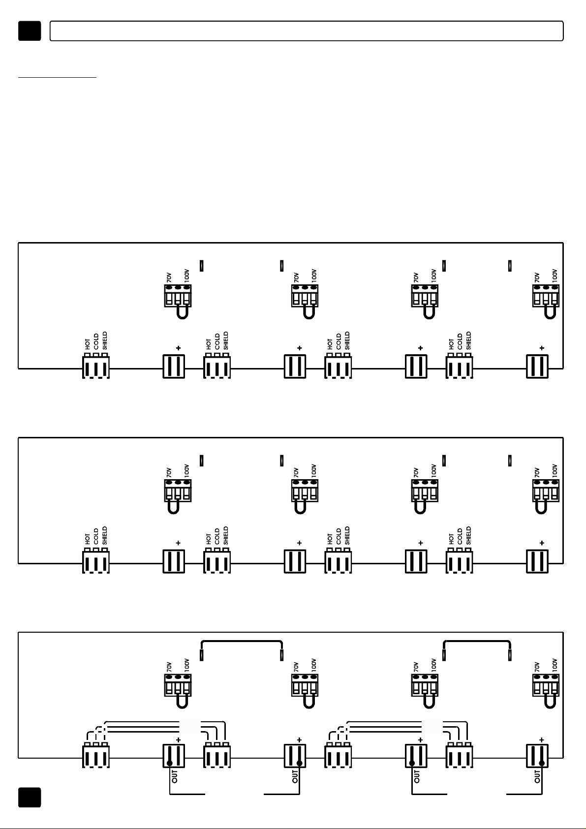
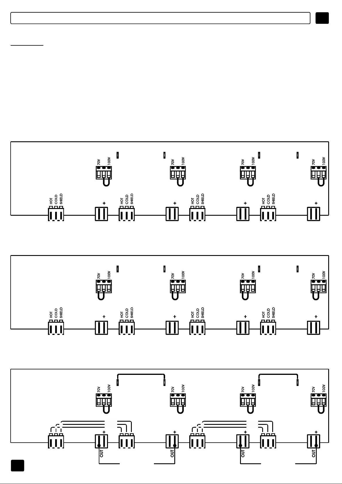
MODODIUTILIZZO
ATTENZIONE
ILCONNETTOREDIUSCITAÈSTATOCOLLEGATOSU100V/166Ohm.PEROTTENERELE
ALTREUSCITEA70VSEGUIRELOSCHEMARIPORTATOSULCOPERCHIO
DELL’APPARECCHIATURA.PERACCEDEREALCONNETTORERIMUOVEREILCOPERCHIO.
PREDISPOSIZIONEINTERNA,ACCESSIBILERIMUOVENDOLAPARTESUPERIORE
DELL’APPARECCHIO,CHEPERMETTELACONFIGURAZIONEDELLEUNITÀDIPOTENZA
COMEDADISEGNO.
MODODIUTILIZZODELL’UNITÀMPU4060
4x60W
USCITAA100V
FS1 FS2 FS3 FS4
M1 M2 M3 M4
4x60W
USCITAA70V
0 0 0 0
J1 J16 J6 J17 J9 J18 J12 J19
OUT OUTINPUTINPUT
SPEAKERS
100V/60W
O
166OHMMIN.
FS1 FS2 FS3 FS4
M1 M2 M3 M4
0 0 0 0
J1 J16 J6 J17 J9 J18 J12 J19
OUT OUTINPUT INPUT
SPEAKERS
70V/60W
O
82OHMMIN.
SPEAKERS
100V/60W
O
166OHMMIN.
SPEAKERS
70V/60W
O
82OHMMIN.
INPUT INPUTOUT OUT
SPEAKERS
100V/60W
O
166OHMMIN.
INPUT INPUTOUT OUT
SPEAKERS
70V/60W
O
82OHMMIN.
SPEAKERS
100V/60W
O
166OHMMIN.
SPEAKERS
70V/60W
O
82OHMMIN.
2x120W
USCITAA100V
9
FS1 FS2 FS3 FS4
M1 M2 M3 M4
SHIELD
COLD
HOT
0 0 0 0
J1 J16 J6 J17 J9 J18 J12 J19
INPUT INPUTINPUTINPUT
SPEAKERS100V/120W
Z=83OHMMIN.
O
INPUT INPUT
SHIELD
COLD
HOT
INPUT
SPEAKERS100V/120W
O
Z=83OHMMIN.
Page 11
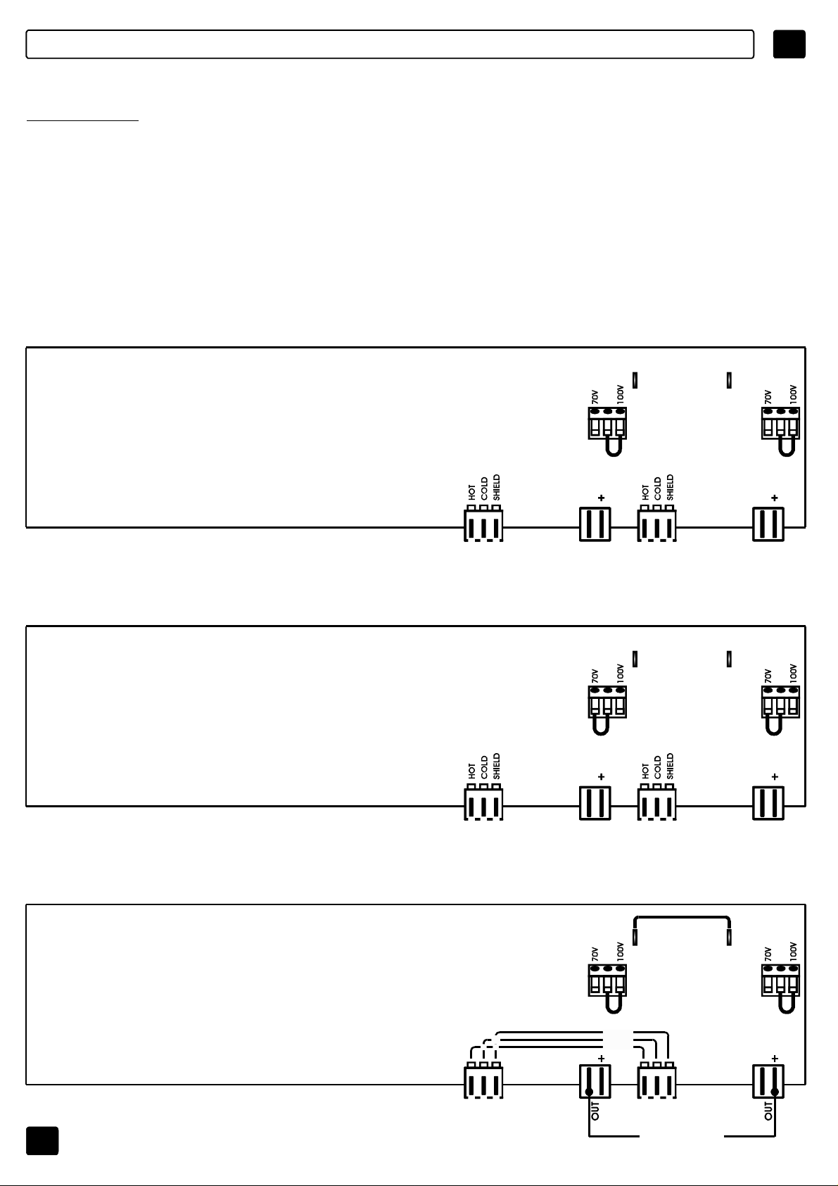
MODODIUTILIZZO
I
ATTENZIONE
ILCONNETTOREDIUSCITAÈSTATOCOLLEGATOSU100V/83Ohm.PEROTTENERELE
ALTREUSCITEA70VSEGUIRELOSCHEMARIPORTATOSULCOPERCHIO
DELL’APPARECCHIATURA.PERACCEDEREALCONNETTORERIMUOVEREILCOPERCHIO.
PREDISPOSIZIONEINTERNA,ACCESSIBILERIMUOVENDOLAPARTESUPERIORE
DELL’APPARECCHIO,CHEPERMETTELACONFIGURAZIONEDELLEUNITÀDIPOTENZA
COMEDADISEGNO.
MODODIUTILIZZODELL’UNITÀMPU2120
2x120W
USCITAA100V
FS3 FS4
M3 M4
2x120W
USCITAA70V
0 0
J9 J18 J12 J19
INPUT INPUTOUT OUT
SPEAKERS
100V/120W
O
83OHMMIN.
FS3 FS4
M3 M4
0 0
J9 J18 J12 J19
INPUT INPUTOUT OUT
SPEAKERS
70V/120W
O
41OHMMIN.
SPEAKERS
100V/120W
O
83OHMMIN.
SPEAKERS
70V/120W
O
41OHMMIN.
1x240W
USCITAA100V
10
FS3 FS4
M3 M4
SHIELD
COLD
HOT
0 0
J9 J18 J12 J19
INPUT INPUT
INPUT
SPEAKERS100V/240W
O
Z=83OHMMIN.
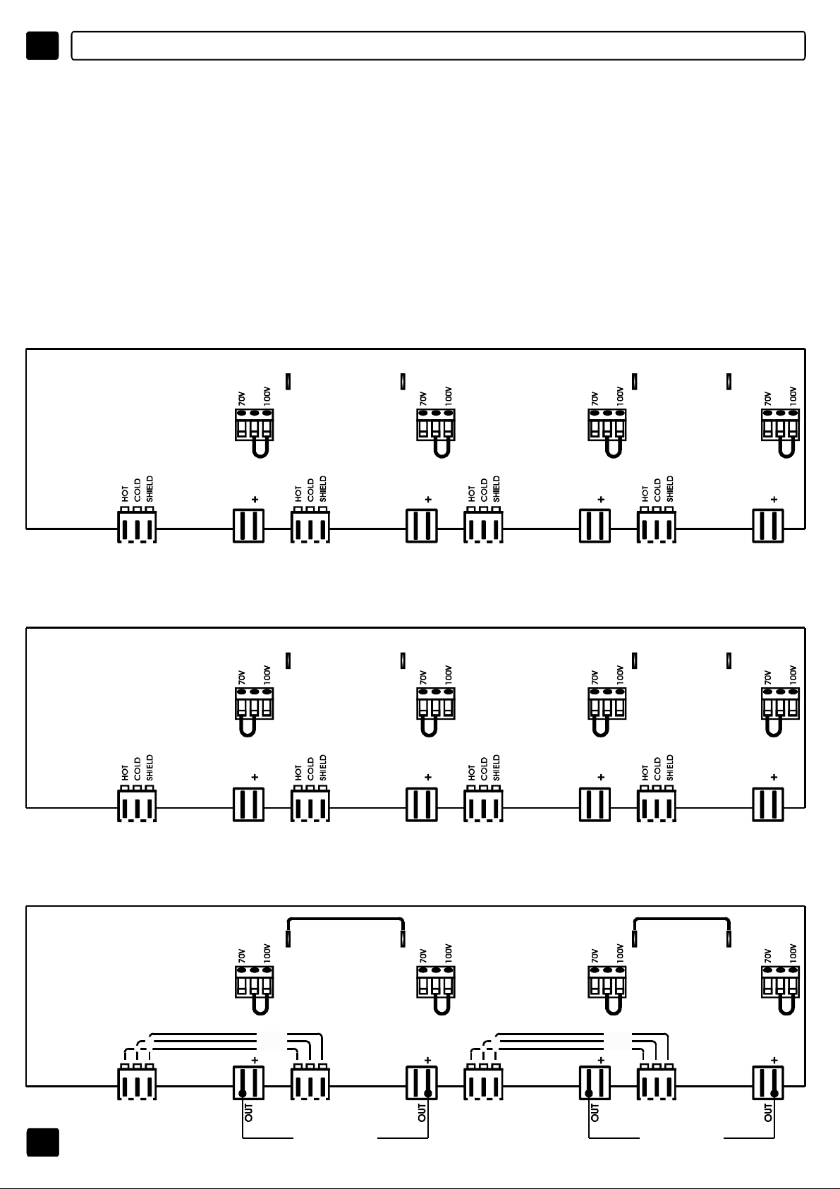
Page 12
I
MODODIUTILIZZO
ATTENZIONE
ILCONNETTOREDIUSCITAÈSTATOCOLLEGATOSU100V/83Ohm.PEROTTENERELE
ALTREUSCITEA70VSEGUIRELOSCHEMARIPORTATOSULCOPERCHIO
DELL’APPARECCHIATURA.PERACCEDEREALCONNETTORERIMUOVEREILCOPERCHIO.
PREDISPOSIZIONEINTERNA,ACCESSIBILERIMUOVENDOLAPARTESUPERIORE
DELL’APPARECCHIO,CHEPERMETTELACONFIGURAZIONEDELLEUNITÀDIPOTENZA
COMEDADISEGNO.
MODODIUTILIZZODELL’UNITÀMPU4120
4x120W
USCITAA100V
FS1 FS2 FS3 FS4
M1 M2 M3 M4
4x120W
USCITAA70V
0
J1 J16 J6 J17 J9 J18 J12 J19
INPUT INPUT INPUT INPUTOUT OUT OUT OUT
SPEAKERS
100V/120W
O
83OHMMIN.
FS1 FS2 FS3 FS4
M1 M2 M3 M4
0 0 0 0
J1 J16 J6 J17 J9 J18 J12 J19
INPUT INPUT INPUT INPUTOUT OUT OUT OUT
SPEAKERS
70V/120W
O
41OHMMIN.
0 0 0
SPEAKERS
100V/120W
O
83OHMMIN.
SPEAKERS
70V/120W
O
41OHMMIN.
SPEAKERS
100V/120W
O
83OHMMIN.
SPEAKERS
70V/120W
O
41OHMMIN.
SPEAKERS
100V/120W
O
83OHMMIN.
SPEAKERS
70V/120W
O
41OHMMIN.
2x240W
USCITAA100V
11
FS1 FS2 FS3 FS4
M1 M2 M3 M4
SHIELD
COLD
HOT
0 0 0 0
J1 J16 J6 J17 J9 J18 J12 J19
INPUT INPUT INPUT INPUT
SPEAKERS100V/240W
O
Z=42OHMMIN.
SHIELD
COLD
HOT
INPUT
SPEAKERS100V/240W
O
Z=42OHMMIN.
Page 13

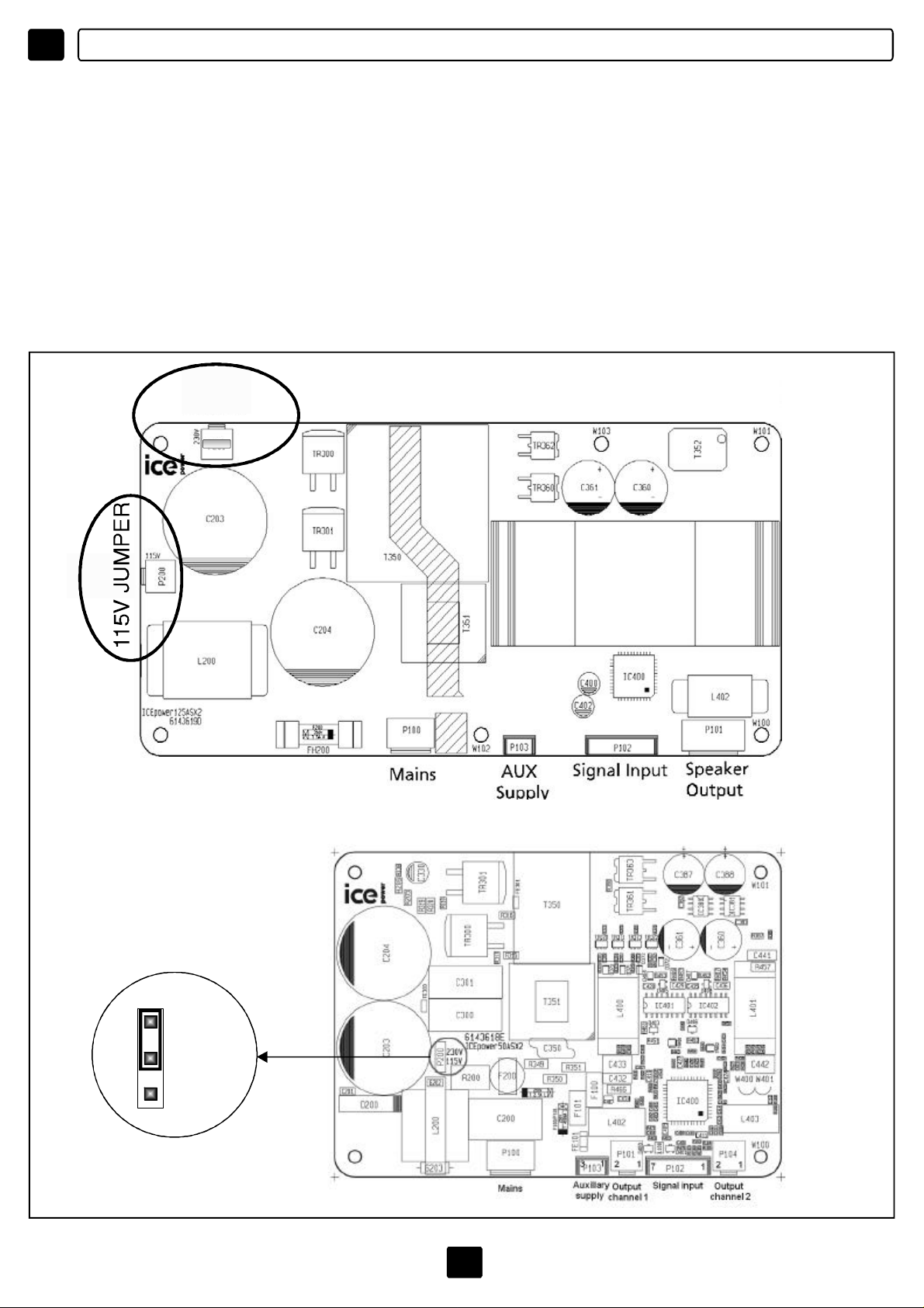
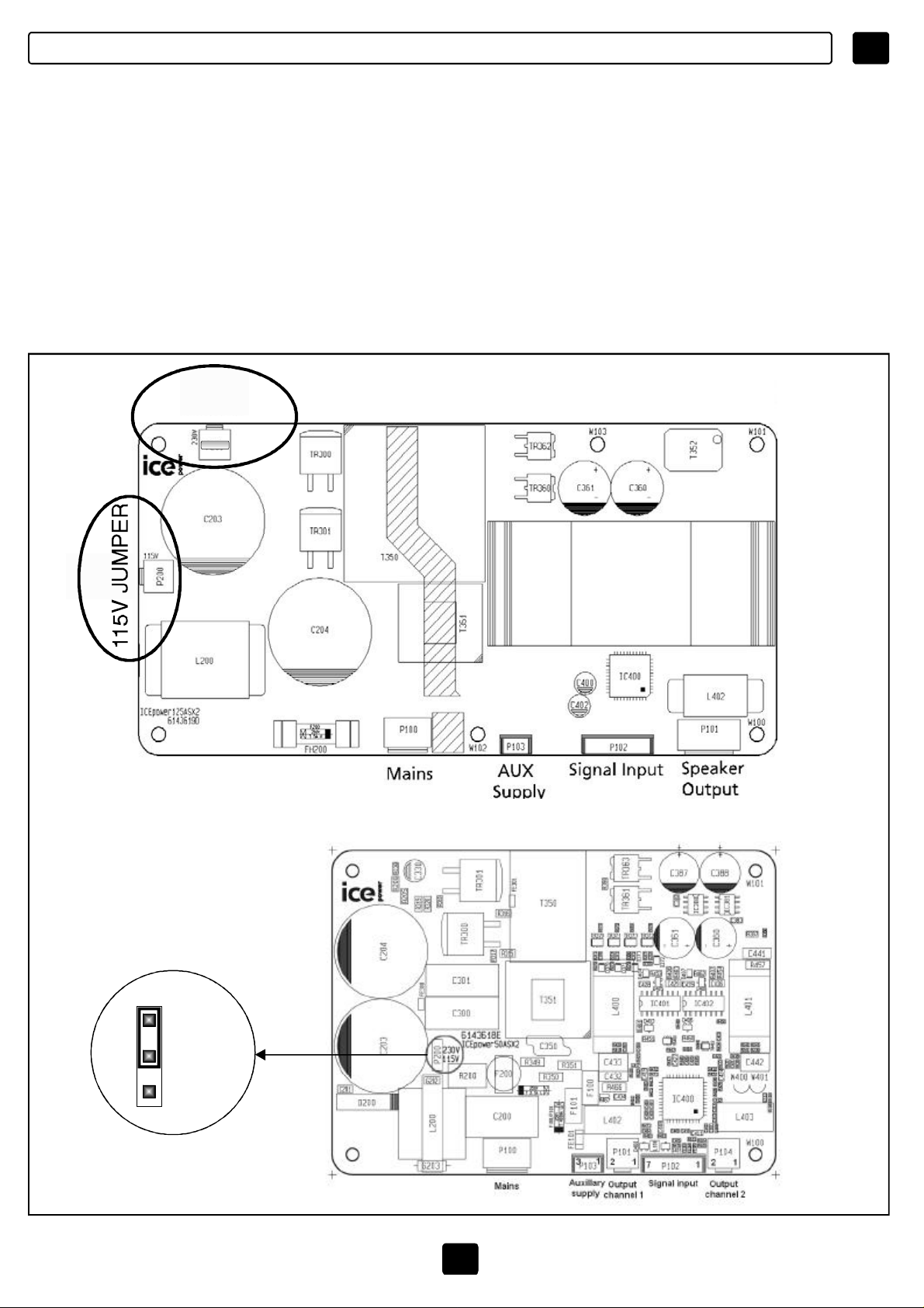
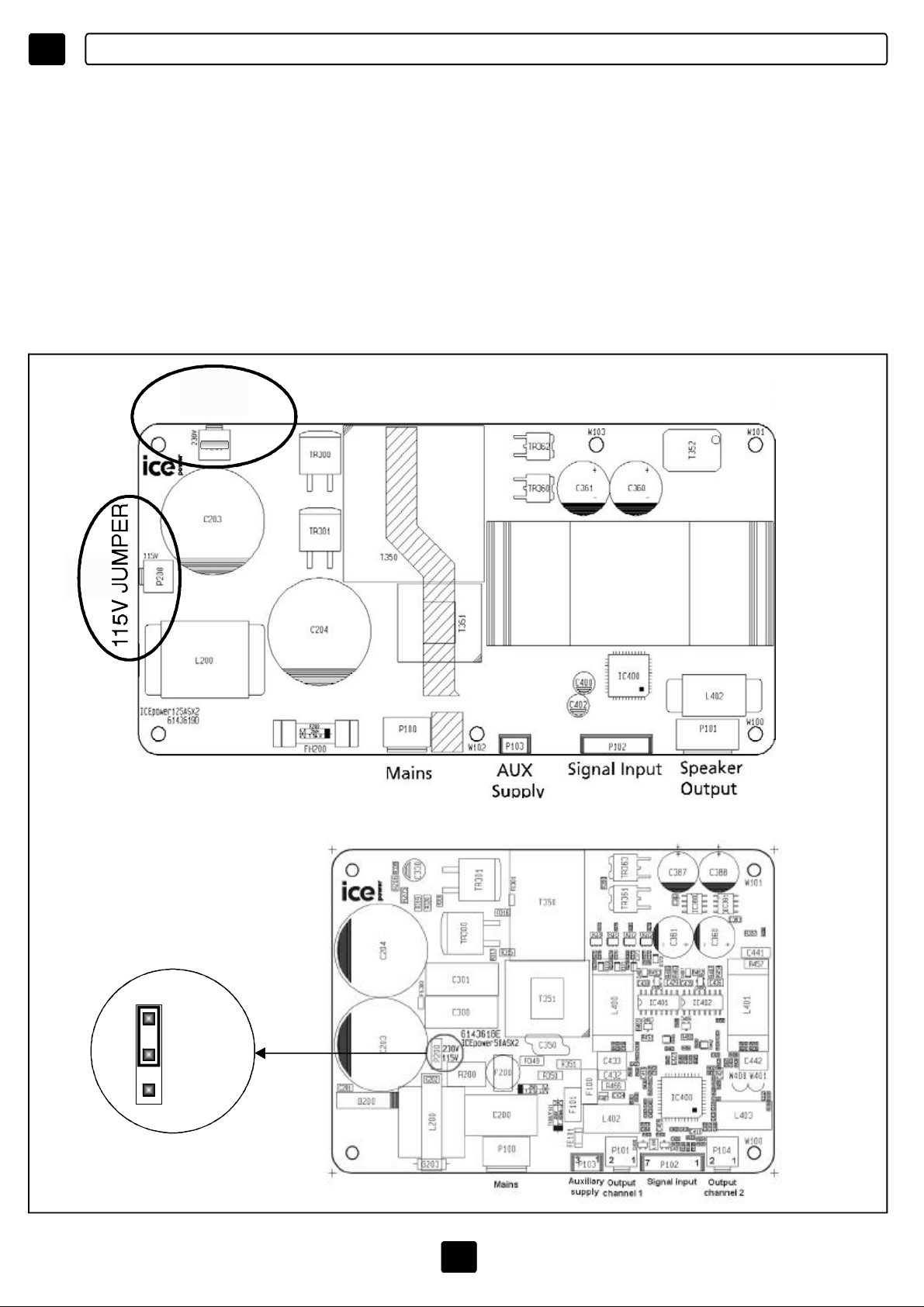
SELEZIONEDELLATENSIONEDIALIMENTAZIONE
Quandosiutilizzal’apparecchiaturaperlaprimavolta,assicurarsichelatensioneapplicata
siacorretta.
Perselezionareilvaloredesideratodellatensionedialimentazione(85-132Vaco170-264
Vac)seguireleistruzioniriportatenellafig.1.
N.B.inserirenell’appositoalloggiamento(vedipag.7)ilfusibileappropriatoalla
tensionedialimentazioneselezionata.
I
230VJUMPER
MPU4240/MPU4120/MPU2120
MPU4060
fig.1
230V
115V
12
Page 14
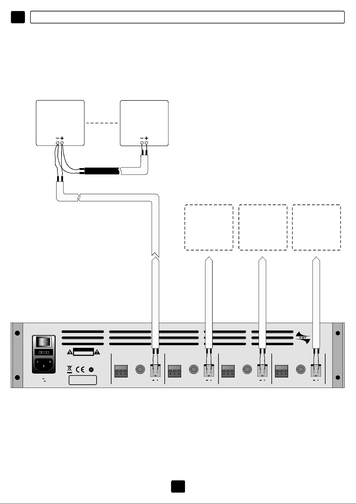
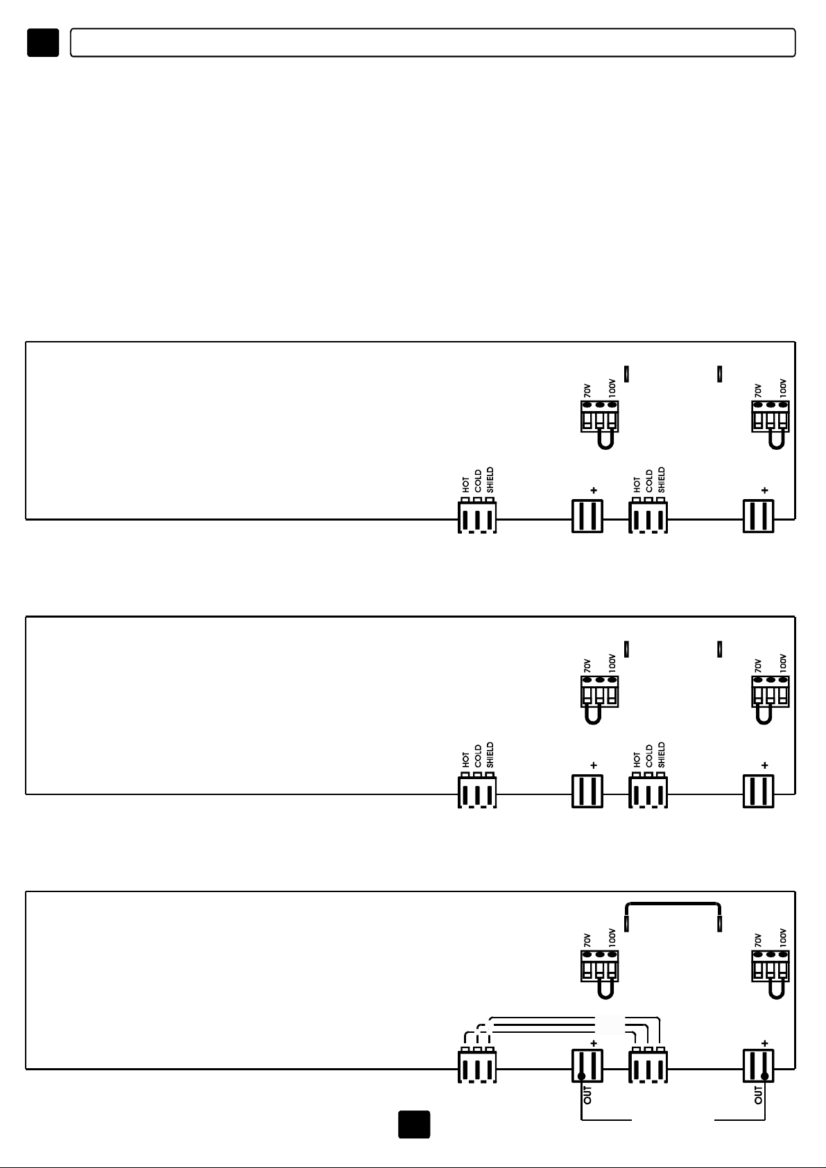
I ESEMPIDICOLLEGAMENTO
USCITE
ZONE
SPEAKER
100VINPUT
ZONE
SPEAKER
100VINPUT
ZONE
SPEAKER
ZONE
SPEAKER
ZONE
SPEAKER
85÷132Vac/T3,15A-250V
170÷264Vac/T1,6A-250V
PowerConsumption250VA
CAUTION
RISKOFELECTRICSHOCK
DONOTOPEN
TOREDUCETHERISKOFELECTRICSHOCKDONOT
REMOVECOVER(ORBACK)NOUSERSERVICEABLE
PARTSINSIDEREFERSERVICINGTOQUALIFIED
SERVICEPERSONNEL
MadeinItaly
H C S
MPU4060
AMPLIFIER1AMPLIFIER4 AMPLIFIER3 AMPLIFIER2
VOLUME OUTINPUT
H C S
VOLUME OUTINPUT
H C S
VOLUME OUTINPUT
H C S
VOLUME OUTINPUT
13
Page 15
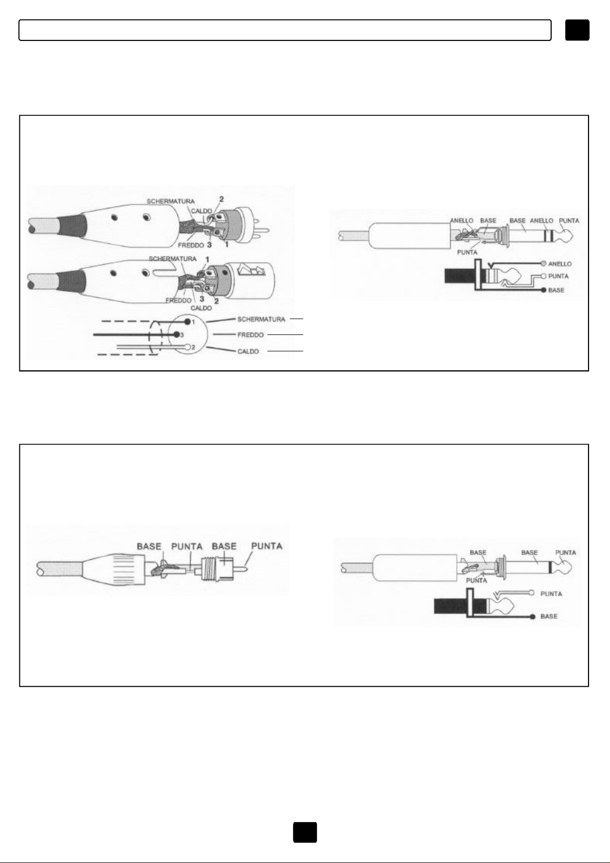
ESEMPIDICOLLEGAMENTO
I
INGRESSI
FONTEBILANCIATA(connettoreXLR) FONTEBILANCIATA(JackTRS/punta-anello-base)
SHIELD
COLD
HOT
BASE=SCHERMATUTA-SHIELD
PUNTA=HOT(+)
ANELLO=COLD(-)
FONTESBILANCIATA(connettoreRCA) FONTESBILANCIATA(JackTS/punta-base)
BASE=SCHERMATUTA-SHIELD
PUNTA=HOT(+)
BASE=SCHERMATUTA-SHIELD
PUNTA=HOT(+)
14
Page 16
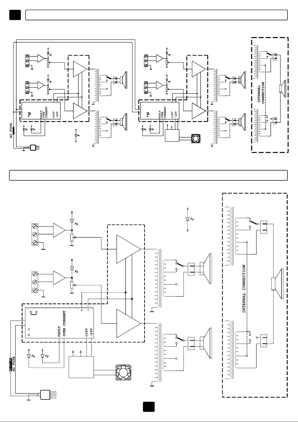
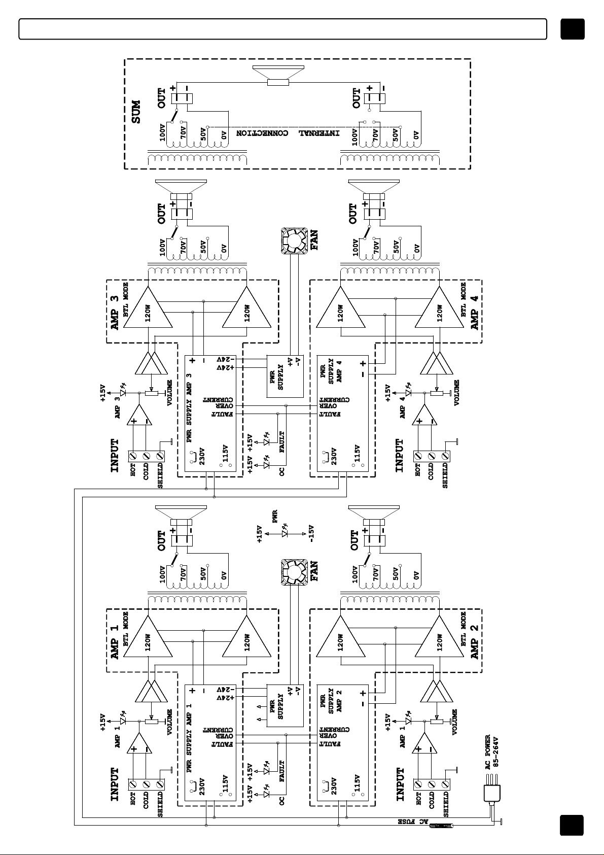
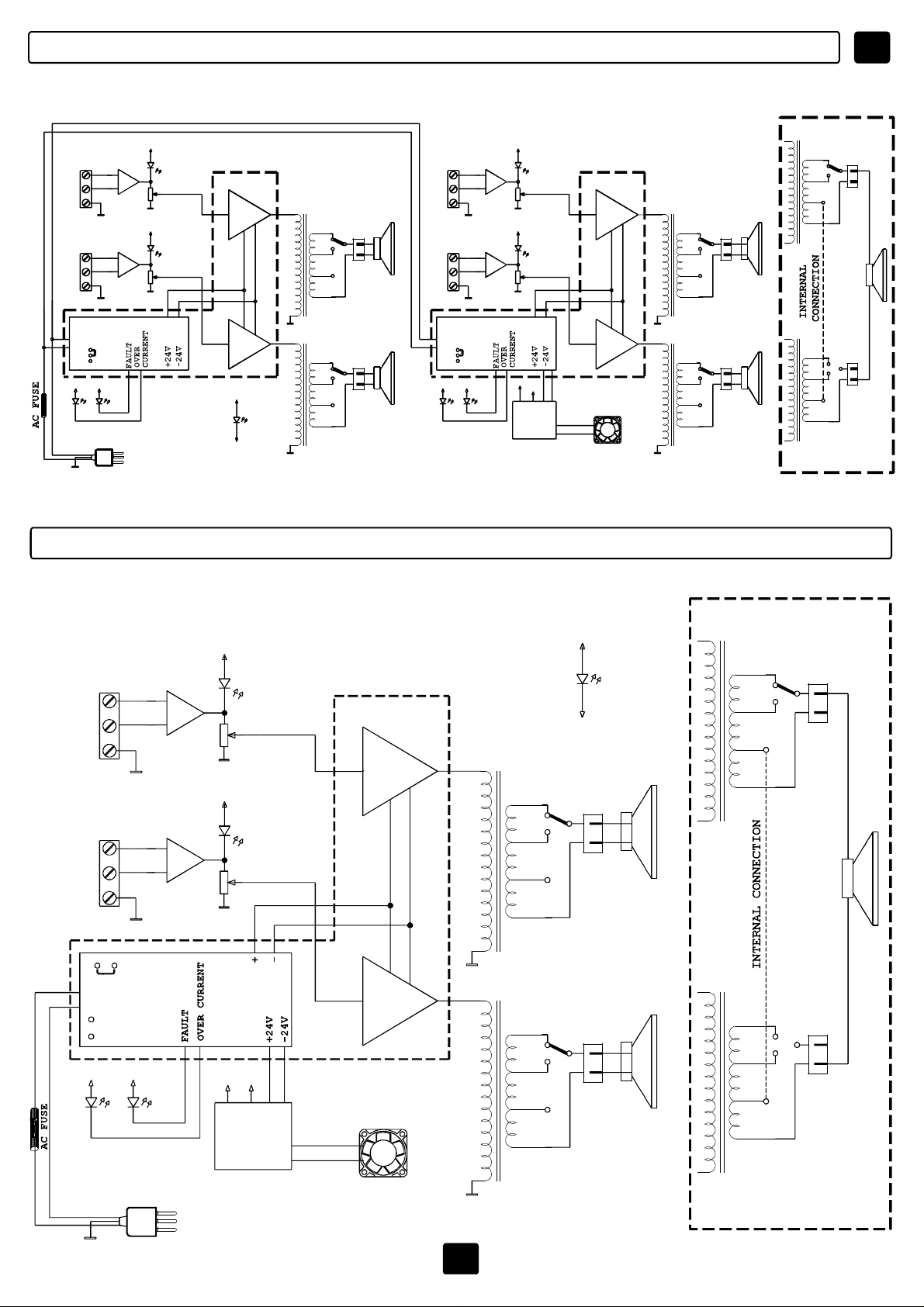
I SCHEMAABLOCCHI
+15V
230V
115V
AMP1
+
-
+15V
AMP2
+
-
ACPOWER
85-264V
VOLUME
VOLUME
+ -
INPUT
HOT
COLD
SHIELD
INPUT
HOT
COLD
SHIELD
PWRSUPPLY
AMP1
+15V +15V
OC FAULT
MPU4060/4120
*
120Wmod4120
AMP
1
*
60W
AMP
*
60W
AMP
+15V
PWR
-15V
100V
70V
50V
0V
100V
70V
50V
0V
OUT
OUT
+15V
230V
115V
AMP3
+
-
AMP4
+
-
VOLUME
+15V
VOLUME
+15V
-15V
PWR
SUPPLY
+ -
AMP
2
*
60W
AMP
*
60W
AMP
+V
-V
FAN
100V
70V
50V
0V
100V
70V
50V
0V
OUT
OUT
+
-
+
-
INPUT
HOT
COLD
SHIELD
+
-
INPUT
HOT
COLD
SHIELD
PWRSUPPLY
AMP2
+
-
+15V +15V
OC FAULT
100V
100V
70V
50V
70V
50V
0V
OUT
+
-
0V
OUT
+
-
SUM
MPU2120
INPUT
HOT
COLD
SHIELD
INPUT
HOT
COLD
SHIELD
PWRSUPPLY
AMPLIFIER
115V
+15V +15V
OC
230V
FAULT
AMP1
+
-
AMP2
+
-
+15V
+15V
+15V
VOLUME
VOLUME
-15V
POWER
SUPPLY
+V
-V
AMPLIFIER
120W
AMP
120W
AMP
100V
70V
50V
0V
100V
70V
50V
0V
+15V
-15V
OUT
OUT
PWR
+
-
+
-
100V
70V
50V
0V
100V
70V
50V
0V
SUM
OUT
+
-
OUT
+
-
ACPOWER
85-264V
FAN
15
Page 17
SCHEMAABLOCCHI
IMPU4240
16
Page 18
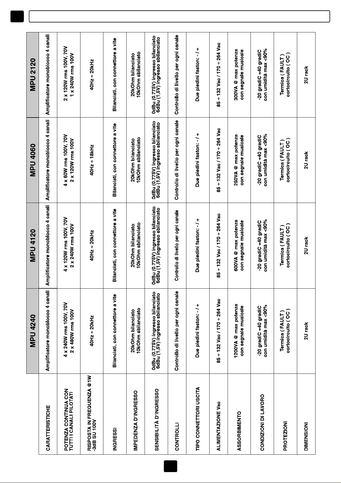
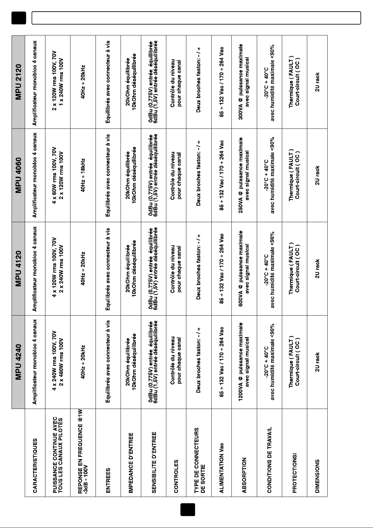
I SPECIFICHETECNICHE
17
Page 19

TABLEOFCONTENTS
UK
CONTENTS-INTRODUCTION
PRECAUTIONS-INSTALLATION
IMPORTANTSAFETYINSTRUCTIONS
CONNECTIONS
FRONTPANEL
REARPANEL
USAGE
SUPPLYVOLTAGE
OUTPUTS
INPUTS
BLOCKDIAGRAM
TECHNICALSPECIFICATIONS
18
19
20
21-22
23
24
25-26-27-28
29
30
31
32-33
34
INTRODUCTION
Toachievethebestinvestment/performanceratio,nowadaysinstallersandendusersare
requestingtheindustryformoreandmorecompleteandversatilesystems,featuring
functionsandatechnologycapableofmeetingthecurrentrequirementsofsound
distribution.
Asystemdesignedaccordingtothesespecificationsshallfeature:enoughpowertodiffuse
thesoundinseveralareas;theminimumpossiblenumberofcomponents;easyassembly;
lowconsumptionduringoperation;andconstantandhighperformance.
Understandingandanticipatingtheseneeds,FBTElettronicaS.p.A.hascreatedanewline
ofamplifiers:,includingthemodels.
MPUMPU2120,MPU4060,MPU4120,MPU4240
Theyaremonoblockpowerunitswithtwoorfourfinalamplifiers,outputswith70Vand100V
linetransformersthatcanoperateinstereoor“sum”modewithtwopossibleconfigurations
foreachpowerunit.
40Hzto20kHzfrequencyresponse,40Hzinternalhigh-passfilter,short-circuitandthermal
protection;onthefrontpanel,lightindicatorsshowingtheoperationalmodeandpossible
existingfailures;volumeadjustmentonthebackpanel.
18
Page 20
UK
!
WARNING
RISKOFELECTRICSHOCK
DONOTOPEN
TOREDUCETHERISKOFELECTRICSHOCK
DONOTREMOVECOVER(ORBACK)
NOUSERSERVICEABLEPARTSINSIDE
REFERSERVICINGTOQUALIFIEDSERVICEPERSONNEL
TOREDUCETHERISKOFFIREORELECTRICSHOCK
DONOTEXPOSETHISEQUIPMENTTORAINORMOISTURE
WHEREMARKED,THISSYMBOLINDICATESADANGEROUSNONISOLATEDVOLTAGEINSIDETHELOUDSPEAKER:
SUCHVOLTAGECOULDBESUFFICIENTTORESULTINTHERISK
OFELECTRICSHOCK.
WHEREMARKED,THISSYMBOLINDICATESIMPORTANTUSAGE
ANDMAINTENANCEINSTRUCTIONSINTHEENCLOSED
DOCUMENTS.PLEASEREFERTOTHEMANUAL.
PRECAUTIONS
!
°Forproperairventilationpleasemakesuretoleavesufficientclearance(min11inc.)onall
sidesofthedevice.
°Pleasedonotcovertheventilationslotswithpapers,tablecloths,curtains,etc.inorder
nottopreventventilationofthedevice.
°Pleasedonotplaceanynakedflamesource,suchaslightedcandles,onthedevice.
°Pleasekeepthedeviceawayfromwaterspringsandsplashesandpleasedonotplace
anyobjectscontainingliquids,suchasvases,onthedevice.
°CAUTION:Toavoidtheriskofinjuriespleasesecurethedevicetothewallfollowingthe
enclosedinstructions.
INSTALLATION
°Whentheunitisinstalledinarackenclosure,therackmusthavealltheprerequisites
requiredbytheEN60439-1standard,inparticulartherearpartmustbeclosedbymeansof
suitablepanels.
19
Page 21

IMPORTANTSAFETYINSTRUCTIONS
1)Readtheseinstructions
2)Keeptheseinstructions
3)Heedallwarnings
4)Followallinstructions
5)Donotusethisapparatusnearwater
6)Cleanonlywithdrycloth
7)Donotblockanyventilationopenings.Installinaccordancewiththemanufacturer’s
instructions.
8)Donotinstallnearanyheatsources,suchasradiators,heatregisters,stovesorother
apparatus(includingamplifiers)thatproduceheat
9)Donotdefeatthesafetypurposeofthepolarizedorgrounding-typeplug.Apolarized
plughastwobladeswithonewiderthantheother.Agroundingtypeplughastwobladesand
athirdgroundingprong.Thewidebladeorthethirdprongareprovidedforyoursafety.Ifthe
providedplugdoesnotfitintoyouroutlet,consultanelectricianforreplacementofthe
obsoleteoutlet.
10)Protectthepowercordfrombeingwalkedonorpinchedparticularlyatplugs,
conveniencereceptacles,andthepointwheretheyexitfromtheapparatus.
11)Onlyuseattachments/accessoriesspecifiedbythemanufacturer.
12)Useonlywiththecart,stand,tripod,bracket,ortablespecifiedbythe
manufacturerorsoldwiththeapparatus.Whenacartisused,usecaution
whenmovingthecart/apparatuscombinationtoavoidinjuryfromtip-over.
13)Unplugthisapparatusduringlightningstormsorwhenunusedforlong
periodsoftime.
14)Referallservicingtoqualifiedservicepersonnel.Servicingisrequired
whentheapparatushasbeendamagedinanyway,suchaspower-supplycordorplugis
damaged,liquidhasbeenspilledorobjectshavefallenintotheapparatus,theapparatus
hasbeenexposedtorainormoisture,doesnotoperatenormally,orhasbeendropped.
UK
THEDEVICEMUSTBECONSTANTLYCONNECTEDTOTHEMAINSTHROUGHA
PERFECTLYFUNCTIONINGGROUNDINGCONDUCTOR.
Thisdevicefeaturesapoweroutlet;installthedevicesothatthesocketforthepowercord
canbeaccessedeasily.
3
20
Page 22

UK CONNECTIONS
!
°Beforeusingtheamplifiermakesurethattheappliance’svoltageisinaccordancetoyour
mainssupply.Connecttheamplifieronlytogroundedmainsoutlets.
°Toavoidtheriskofelectricalshocknevertouchthebareconductorsleadingtotheoutput
terminalsoftheamplifierwhenitisinoperation.
°Theunitmustonlybesuppliedfromthemainsafterallconnectionshavebeencompleted.
°
TOCONNECTLOUDSPEAKERSUSEBOOT’SCABLESEXCLUSIVELY
1)
LOWIMPEDANCELINES
-Thetotalimpedanceofthespeakersconnectedmustcorrespondtothatselectedonthe
amplifier’soutputterminals
2)
CONSTANTVOLTAGELINES
-Eachspeakermustbeequippedwithalinetransformerwithaninputvoltageequaltothat
oftheline(70,100V)
°Thesumofthepowercapacitiesofthespeakersmustnotexceedtheoutputpower
capacityoftheamplifier
21
Page 23
CONNECTIONS
INPUTWIRING
UK
1)Useonlyshieldedcablesforallinputconnections.Cableswithshieldingfilmsorwith
highdensitybraidsarebetter.Thecablesshieldedusingtwistedstrands,eventhough
extremelyflexible,canbedamagedovertimeandcancausenoiseproblems.
2)Ifpossible,donotuseunbalancedlines;iftheymustbeused,cablesshallbeasshortas
possible.
3)Beforechangingtheconnectorsortheinputcables,turntheamplifierlevelcontroltothe
minimumposition(anticlockwise).
4)Beforechangingtheoutputconnections,turntheamplifierleveltotheminimumand
switchofftheACpowersupplytominimizethepossibilityofshort-circuitsonoutputs.
DISTRIBUITEDSPEAKERSYSTEMS
Thedistributedspeakersystemsformusicandpagingareoftenusedinhotels,restaurants,
offices,schools,etc.Inthesesystemsseveralspeakersarelocatedalloverthearea.
Thesemultispeakersystemsincludeoneamplifieroroneamplificationchannelthatdrives
oneormorespeakersequippedwithtransformers.
Thetransformersreducethelinevoltagetoalowerlevel,sotodrivespeakers,andare
connectedbetweentheconductorpair.Comparedtoasinglespeaker,thecombinationofa
transformerandaspeakeronthelinehasamuchhigherimpedancetowardtheamplifier,
andthismakesitpossibletoaddseveralspeakerstoasinglepowersignalline.
100V
22
Standarddistributedspeakersystem
3
100V
POWERAMPLIFIER
Page 24
UK CONTROLSANDFUNCTIONS
FRONTPANEL
MPU4240/MPU4120/MPU4060/MPU2120
2
1
FOURCHANNELSPOWERUNIT
AMPLIFIER1/2
4
3
AMP2AMP1 OC FAULT AMP4AMP3 OC FAULT
[1-4]AMP1/2/3/4:
2
1
AMPLIFIER3/4
4
3
5
MPU4240
PWR
WhentheLEDlightsup,thesignalisontherelevantamplifier.
[2]OC:
OVERCURRENT_
whentheLEDlightsup,thecurrentabsorbedbyaload(and,
hence,thepower)isexceedingthecurrentthatcanbesuppliedandsupportedbytheline,
orashort-cuthasoccurredontheline.
[3]FAULT:
WhentheLEDlightsup,acomponentmaybebrokenorthethermalprotection
hasactivated:thiscanoccurduetoexcessiveheat,overchargeorduetoatoohighaudio
signalatanexcessivelyhighfrequency.Inthiscase,toavoiddamagestothepowercircuits,
theprotectionactivates,temporarilyinterruptingamplificationuntiloptimalconditionsare
restored.
[5]PWR
:Indicatesthatthesystemison.
23
Page 25

CONTROLSANDFUNCTIONS
REARPANEL
MPU4240/MPU4120/MPU4060/MPU2120
6 7 8 9 7 8 9 7 8 9 7 8 9
MPU4060
CAUTION
RISKOFELECTRICSHOCK
DONOTOPEN
TOREDUCETHERISKOFELECTRICSHOCKDONOT
REMOVECOVER(ORBACK)NOUSERSERVICEABLE
PARTSINSIDEREFERSERVICINGTOQUALIFIED
SERVICEPERSONNEL
AMPLIFIER1AMPLIFIER4 AMPLIFIER3 AMPLIFIER2
UK
85÷132Vac/T3,15A-250V
170÷264Vac/T1,6A-250V
PowerConsumption250VA
[6]ALIMENTAZIONE
MadeinItaly
H C S
VOLUME OUTINPUT
H C S
VOLUME OUTINPUT
H C S
VOLUME OUTINPUT
:Socketformainsconnection,systempowerswitchandhousingof
H C S
VOLUME OUTINPUT
powercircuitprotectionfuse.Ifthefusebreaks,itshallonlybereplacedbyfuseswithequal
electricalfeatures.
[7]INPUT:
Three-pinconnectorswithscrewlocking,theyenabletheconnectionofthe
Tochangethesupplyvoltagevalueseepage29
inputsignalsofamplifiers1/2/3/4.
Onlyuseshieldedcablesavoidingunbalancedlines(otherwise,cablesshallbeasshortas
possible).
Beforechanginginputcablesorconnectors,turnthelevelcontrolsoftheamplifierstothe
minimum.
[8]VOLUME:
Adjustmentoftheoutputleveloftheamplifiers.
[9]OUT:Outputconnectorswithtwofastonforconnectingspeakerswiththe100V/70Vline
transformer.Configurationsinstereoor“sum”modeareavailable.
(seepage25-26-27-28)
3
24
Page 26

UK
APPLICATIONMODE
CAUTION
THEOUTPUTCONNECTORHASBEENCONNECTEDTO100V/42ohm.TOOBTAINOTHER
70VOUTPUTS,FOLLOWTHEDIAGRAMONTHECOVEROFTHEDEVICE.TOACCESSTHE
CONNECTOR,REMOVETHECOVER.
THEINTERNALPRESET,ACCESSIBLEREMOVINGTHEUPPERPARTOFTHEDEVICE,MAKES
ITPOSSIBLETOCONFIGURETHEPOWERUNITSASSHOWNBYTHEDRAWING.
MPU4240APPLICATIONMODE
4x240W
100VOUT
4x240W
70VOUT
FS1 FS2 FS3 FS4
M1 M2 M3 M4
0 0 0 0
J1 J16 J6 J17 J9 J18 J12 J19
INPUT INPUT INPUT INPUTOUT OUT OUT OUT
SPEAKERS
100V/240W
OR
42OHMMIN.
FS1 FS2 FS3 FS4
M1 M2 M3 M4
SPEAKERS
100V/240W
OR
42OHMMIN.
SPEAKERS
100V/240W
OR
42OHMMIN.
SPEAKERS
100V/240W
OR
42OHMMIN.
2x480W
100VOUT
25
0 0 0 0
J1 J16 J6 J17 J9 J18 J12 J19
INPUT INPUT INPUT INPUTOUT OUT OUT OUT
SPEAKERS
70V/240W
OR
21OHMMIN.
FS1 FS2 FS3 FS4
M1 M2 M3 M4
SHIELD
COLD
HOT
0 0 0 0
J1 J16 J6 J17 J9 J18 J12 J19
INPUT INPUT INPUT INPUT
SPEAKERS100V/480W
OR
Z=21OHMMIN.
SPEAKERS
70V/240W
OR
21OHMMIN.
SPEAKERS
70V/240W
OR
21OHMMIN.
SHIELD
COLD
HOT
INPUT
SPEAKERS100V/480W
OR
Z=21OHMMIN.
SPEAKERS
70V/240W
OR
21OHMMIN.
Page 27
APPLICATIONMODE
UK
CAUTION
THEOUTPUTCONNECTORHASBEENCONNECTEDTO100V/166ohm.TOOBTAINOTHER
70VOUTPUTS,FOLLOWTHEDIAGRAMONTHECOVEROFTHEDEVICE.TOACCESSTHE
CONNECTOR,REMOVETHECOVER.
THEINTERNALPRESET,ACCESSIBLEREMOVINGTHEUPPERPARTOFTHEDEVICE,MAKES
ITPOSSIBLETOCONFIGURETHEPOWERUNITSASSHOWNBYTHEDRAWING.
MPU4060APPLICATIONMODE
4x60W
100VOUT
FS1 FS2 FS3 FS4
M1 M2 M3 M4
4x60W
70VOUT
0 0 0 0
J1 J16 J6 J17 J9 J18 J12 J19
OUT OUTINPUTINPUT
SPEAKERS
100V/60W
OR
166OHMMIN.
FS1 FS2 FS3 FS4
M1 M2 M3 M4
0 0 0 0
J1 J16 J6 J17 J9 J18 J12 J19
OUT OUTINPUT INPUT
SPEAKERS
70V/60W
OR
82OHMMIN.
SPEAKERS
100V/60W
OR
166OHMMIN.
SPEAKERS
70V/60W
OR
82OHMMIN.
INPUT INPUTOUT OUT
SPEAKERS
100V/60W
OR
166OHMMIN.
INPUT INPUTOUT OUT
SPEAKERS
70V/60W
OR
82OHMMIN.
SPEAKERS
100V/60W
OR
166OHMMIN.
SPEAKERS
70V/60W
OR
82OHMMIN.
2x120W
100VOUT
26
FS1 FS2 FS3 FS4
M1 M2 M3 M4
SHIELD
COLD
HOT
0 0 0 0
J1 J16 J6 J17 J9 J18 J12 J19
INPUT INPUTINPUTINPUT
SPEAKERS100V/120W
Z=83OHMMIN.
OR
INPUT INPUT
SHIELD
COLD
HOT
INPUT
SPEAKERS100V/120W
OR
Z=83OHMMIN.
Page 28

UK
APPLICATIONMODE
CAUTION
THEOUTPUTCONNECTORHASBEENCONNECTEDTO100V/83ohm.TOOBTAINOTHER
70VOUTPUTS,FOLLOWTHEDIAGRAMONTHECOVEROFTHEDEVICE.TOACCESSTHE
CONNECTOR,REMOVETHECOVER.
THEINTERNALPRESET,ACCESSIBLEREMOVINGTHEUPPERPARTOFTHEDEVICE,MAKES
ITPOSSIBLETOCONFIGURETHEPOWERUNITSASSHOWNBYTHEDRAWING.
MPU2120APPLICATIONMODE
2x120W
100VOUT
FS3 FS4
M3 M4
2x120W
70VOUT
0 0
J9 J18 J12 J19
INPUT INPUTOUT OUT
SPEAKERS
100V/120W
OR
83OHMMIN.
FS3 FS4
M3 M4
0 0
J9 J18 J12 J19
INPUT INPUTOUT OUT
SPEAKERS
70V/120W
OR
41OHMMIN.
SPEAKERS
100V/120W
OR
83OHMMIN.
SPEAKERS
70V/120W
OR
41OHMMIN.
1x240W
100VOUT
27
FS3 FS4
M3 M4
SHIELD
COLD
HOT
0 0
J9 J18 J12 J19
INPUT INPUT
INPUT
SPEAKERS100V/240W
OR
Z=83OHMMIN.
Page 29
APPLICATIONMODE
UK
CAUTION
THEOUTPUTCONNECTORHASBEENCONNECTEDTO100V/83ohm.TOOBTAINOTHER
70VOUTPUTS,FOLLOWTHEDIAGRAMONTHECOVEROFTHEDEVICE.TOACCESSTHE
CONNECTOR,REMOVETHECOVER.
THEINTERNALPRESET,ACCESSIBLEREMOVINGTHEUPPERPARTOFTHEDEVICE,MAKES
ITPOSSIBLETOCONFIGURETHEPOWERUNITSASSHOWNBYTHEDRAWING.
MPU4120APPLICATIONMODE
4x120W
100VOUT
FS1 FS2 FS3 FS4
M1 M2 M3 M4
4x120W
70VOUT
0
J1 J16 J6 J17 J9 J18 J12 J19
INPUT INPUT INPUT INPUTOUT OUT OUT OUT
SPEAKERS
100V/120W
OR
83OHMMIN.
FS1 FS2 FS3 FS4
M1 M2 M3 M4
0 0 0 0
J1 J16 J6 J17 J9 J18 J12 J19
INPUT INPUT INPUT INPUTOUT OUT OUT OUT
SPEAKERS
70V/120W
OR
41OHMMIN.
0 0 0
SPEAKERS
100V/120W
OR
83OHMMIN.
SPEAKERS
70V/120W
OR
41OHMMIN.
SPEAKERS
100V/120W
OR
83OHMMIN.
SPEAKERS
70V/120W
OR
41OHMMIN.
SPEAKERS
100V/120W
OR
83OHMMIN.
SPEAKERS
70V/120W
OR
41OHMMIN.
2x240W
100VOUT
28
FS1 FS2 FS3 FS4
M1 M2 M3 M4
SHIELD
COLD
HOT
0 0 0 0
J1 J16 J6 J17 J9 J18 J12 J19
INPUT INPUT INPUT INPUT
SPEAKERS100V/240W
OR
Z=42OHMMIN.
SHIELD
COLD
HOT
INPUT
SPEAKERS100V/240W
OR
Z=42OHMMIN.
Page 30
UK
Whenusingthedeviceforthefirsttime,makesuretheappliedvoltageiscorrect.
Toselectthedesiredvalueforsupplyvoltage(85-132Vacor170-264Vac),followthe
instructionsshowninPicture1.
NB:putintherelevanthousing(seepage24)thefusesuitableforthesupply
voltageselected.
SUPPLYVOLTAGESELECTION
230VJUMPER
MPU4240/MPU4120/MPU2120
MPU4060
fig.1
230V
115V
29
Page 31
OUTPUTS
UKCONNECTIONEXAMPLE
ZONE
SPEAKER
100VINPUT
ZONE
SPEAKER
100VINPUT
ZONE
SPEAKER
ZONE
SPEAKER
ZONE
SPEAKER
85÷132Vac/T3,15A-250V
170÷264Vac/T1,6A-250V
PowerConsumption250VA
CAUTION
RISKOFELECTRICSHOCK
TOREDUCETHERISKOFELECTRICSHOCKDONOT
REMOVECOVER(ORBACK)NOUSERSERVICEABLE
DONOTOPEN
PARTSINSIDEREFERSERVICINGTOQUALIFIED
SERVICEPERSONNEL
MadeinItaly
H C S
MPU4060
AMPLIFIER1AMPLIFIER4 AMPLIFIER3 AMPLIFIER2
VOLUME OUTINPUT
H C S
VOLUME OUTINPUT
H C S
VOLUME OUTINPUT
H C S
VOLUME OUTINPUT
30
Page 32

UK
CONNECTIONEXAMPLE
INPUTS
BALANCEDSOURCE(XLRconnector) BALANCEDSOURCE(JackTRS/tip-ring-sleeve)
SHIELD
HOT
RING SHIELD TIPRINGSLEEVE
COLD
SHIELD
COLD
HOT
SHIELD
COLD
HOT
TIP
RING
TIP
SHIELD
SHIELD=SCHERMATURA
TIP=HOT(+)
RING=COLD(-)
UNBALANCEDSOURCE(RCAconnector) UNBALANCEDSOURCE(JackTS/tip-sleeve)
SHIELD TIP TIPSHIELD
SLEEVE=SHIELD
TIP=HOT(+)
31
SHIELD SHIELD
TIP
SLEEVE=SHIELD
TIP=HOT(+)
TIP
TIP
SHIELD
Page 33
UKBLOCKDIAGRAM
+15V
230V
115V
AMP1
+
-
+15V
AMP2
+
-
ACPOWER
85-264V
VOLUME
VOLUME
+
INPUT
HOT
COLD
SHIELD
INPUT
HOT
COLD
SHIELD
PWRSUPPLY
AMP1
+15V +15V
OC FAULT
MPU4060/4120
SUM
230V
115V
AMP3
+
-
AMP4
+
-
+15V
VOLUME
+15V
VOLUME
+15V
-15V
PWR
SUPPLY
100V
OUT
AMP
2
*
60W
AMP
-
+
+V
-V
*
60W
AMP
FAN
100V
70V
50V
0V
100V
70V
50V
0V
OUT
OUT
+
-
+
-
70V
50V
0V
100V
70V
50V
0V
+
-
OUT
+
-
*
120Wmod4120
AMP
1
*
60W
AMP
-
*
60W
AMP
+15V
-15V
PWR
100V
70V
50V
0V
100V
70V
50V
0V
OUT
OUT
+
-
+
-
INPUT
HOT
COLD
SHIELD
INPUT
HOT
COLD
SHIELD
PWRSUPPLY
AMP2
+15V +15V
OC FAULT
MPU2120
INPUT
HOT
COLD
SHIELD
INPUT
HOT
COLD
SHIELD
PWRSUPPLY
AMPLIFIER
115V
+15V +15V
OC
230V
FAULT
AMP1
+
-
AMP2
+
-
+15V
+15V
+15V
VOLUME
VOLUME
-15V
POWER
SUPPLY
+V
-V
AMPLIFIER
120W
AMP
120W
AMP
100V
70V
50V
0V
100V
70V
50V
0V
+15V
-15V
OUT
OUT
PWR
+
-
+
-
100V
70V
50V
0V
100V
70V
50V
0V
SUM
OUT
+
-
OUT
+
-
ACPOWER
85-264V
FAN
32
Page 34

UK MPU4240
BLOCKDIAGRAM
33
Page 35

UKTECHNICALSPECIFICATIONS
34
Page 36

F
INDEX
INDEX-INTRODUCTION
PRECAUTIONS-INSTALLATION
INSTRUCTIONSDESECURITEIMPORTANTES
CONNEXIONS
PANNEAUANTERIEUR
PANNEAUPOSTERIEUR
MODED’EMPLOI
TENSIOND’ALIMENTATION
SORTIES
ENTREES
SCHEMA-BLOC
SPECIFICATIONSTECHNIQUES
35
36
37
38-39
40
41
42-43-44-45
46
47
48
49-50
51
INTRODUCTION
Pouroptimiserlerapportentrelesinvestissementsetlesprestations,lesinstallateursetles
utilisateursfinauxdemandentaujourd'huiàl'industriedessystèmestoujourspluscomplets
etuniversels,enmesurederépondre,pourlesfonctionsetlatechnologie,auxexigences
modernesdedistributionsonore.
Unsystèmeprojetéensuivantcesindicationsdoitdisposerd'unepuissancesuffisantepour
sonoriserplusieurszones,unnombreminimumdecomposants,unefacilitéd'assemblage,
uneexploitationàbonmarché,desprestationsélevéesetconstantes.
LaFBTElettronica S.p.A.,eninterprétantetprévoyanttellesnécessités,aréaliséune
nouvellegammed'amplificateurs:lasériequicomprendlesmodèles
MPUMPU2120,
MPU4060,MPU4120,MPU4240.
Ils'agitd'unitésdepuissancemonoblocavecdeuxouquatreextrémités,sortiesavecdes
transformateursdeligneà70Vet100Vquipeuventtravaillerenmodalitéstéréoou«
somme»avec2configurationspossiblespourchaqueunitédepuissance.
Réponseenfréquencede40Hzà20kHz,filtreinternepasse-hautà40Hz,protection
thermiqueetcourts-circuits;surlepanneaufrontal,voyantslumineuxdelamodalitéde
travailetdelaprésencedepannes,réglagesdesvolumessurlepanneaupostérieur.
35
Page 37

ATTENTION
RISQUEDECHOCÉLECTRIQUE
NEPASOUVRIR
F
!
!
POURÉVITERLERISQUEDECHOCÉLECTRIQUE
NEPASUTILISERD’OUTILSMECANIQUESÀL’INTÉRIEUR
CONTACTERUNCENTRED’ASSISTANCEQUALIFIÉ
POURÉVITERLERISQUED’INCENDIEOUDECHOCÉLECTRIQUE
NEPASEXPOSERL’APPAREILLAGEÀLAPLUIE
CESYMBOLEINDIQUE,ÀL'ENDROITOÙILAPPARAÎT,LA
PRÉSENCED'UNETENSIONDANGEREUSENONISOLÉEÀ
L'INTÉRIEUR:LEVOLTAGEPEUTÊTRESUFFISANTPOUR
PROVOQUERUNESECOUSSEÉLECTRIQUE.
CESYMBOLEINDIQUE,ÀL'ENDROITOÙILAPPARAÎT,LA
PRÉSENCED'INSTRUCTIONSIMPORTANTESPOUR
L'UTILISATIONETPOURL'ENTRETIENDANSLA
DOCUMENTATIONJOINTE.VEUILLEZCONSULTERLEMANUEL.
NEPASOUVRIRLECOUVERCLE
OUÀL’HUMIDITÉ
PRECAUTIONS
°Pourpermettreuneventilationsuffisante,ilestnécessairedeprévoirunedistance
minimalede30cmenvironpourtouslescôtésdel'appareil.
°Laventilationnedoitpasêtreempêchéeencouvrantlesouverturesdeventilationavec
desobjets,telsquedesjournaux,nappes,rideaux,etc.
°Aucunesourcedeflammenue,tellesquedesbougiesallumées,nedoitêtremisesur
l'appareil.
°L'appareilnedoitpasêtreexposéàdeséclaboussuresouàdesgoutteset,par
conséquent,aucunobjetcontenantduliquidenedoitêtreposésurl'appareil,commepar
ex.desvases.
INSTALLATION
°Sil'appareilestinstallédansunconteneurrack,celui-cidevradisposerdetoutesles
qualitésrequisesprévuesparlanormeEN60439-1,lapartiepostérieuredevranotamment
êtreferméeaumoyendupanneaudisposéàceteffet.
36
Page 38

F
1)Lisezcesinstructions
2)Conservezcesinstructions
3)Faitesattentionàtouslesavertissements
4)Suiveztouteslesinstructions
5)N'employezpascedispositifprèsdel'eau
6)Nenettoyezqu'avecuntorchonsec
7)N’obstruezpaslesouverturesdelaventilation.L’installationdoitêtreeffectuéeselonles
instructionsfourniesparleproducteur.
8)Nel'installezpasprèsdesourcesdechaleurcommeradiateurs,appareilsdechauffage,
poêlesoud'autresappareils(ycomprislesamplificateurs)quiproduisentdelachaleur
9)Nesupprimezpaslesdispositifsdesécuritédesfichespolariséesouavecmiseàlaterre.
Lesfichespolariséessontéquipéesdedeuxbornesdelargeurdifférente.Uneficheavec
miseàlaterreadeuxbornesetuntroisièmepôledeterre.Labornepluslargeoule
troisièmepôlesontnécessairespourlasécuritédel'utilisateur.Silafichefournien'estpas
appropriéepourvotreprise,consultezunélectricienpourleremplacementdelafiche.
10)Protégezlecâbled'alimentationdupiétinementetdelacompression,enparticulieroù
l'ontrouvedesfiches,desrallongesetdanslepointoùilssortentdel'appareil.
11)Employezuniquementdesdispositifsenoption/accessoiresindiquésparleproducteur.
12)Aemployeruniquementavecdeschariots,dessupports,destrépieds,
desconsolesoudestablesindiquésparleproducteurouvendusavec
l'appareil.Sivousutilisezunchariot,faitesattentionpendantledéplacement
contemporainduchariotetdel'appareil,afind'éviterdesdommagesdusau
possiblerenversement.
13)Débranchezlaficheencasd'orageoulorsqu'onn'utilisepasl'appareil
pendantunelonguepériode.
14)Pourl'assistancetechnique,adressez-vousaupersonnelqualifié.L'assistance
techniqueestnécessaireaucasoùl'appareilestendommagé,parex.àcausede
problèmesducâbled'alimentationoudelafiche,durenversementdeliquidesoud'objets
tombésàl'intérieurdel'appareil,del'expositionàlapluieouàl'humidité,d'anomaliesde
fonctionnementoudechutesdel'appareil.
INFORMATIONSDESÉCURITÉIMPORTANTES
L'APPAREILDOITETREBRANCHEAURESEAUELECTRIQUEAUMOYEND'UNEFICHE
AVECUNELIAISONALATERREDEPROTECTION.
Cetappareilestéquipéd'unefiched'alimentation;installerl'appareildesorteàcequela
ficheducordond'alimentationsoitfacilementaccessible.
37
Page 39

CONNEXIONS
F
!
°Avantd'utiliserl'appareillage,s'assurerquelatensionappliquéesoitcorrecte.Brancher
l'amplificateuruniquementsurdesfichesdecourantavecréférenceàlamasse.
°Pouréviterdesrisquesdesecousseélectrique,nejamaistoucherlesfilsdénudés
branchésauxbornesdel'amplificateur,lorsquecelui-ciestenfonction.
°L'appareildoitêtrealimentéparlatensionduréseauuniquementaprèsavoirterminé
touteslesliaisons.
°LESLIGNESD'ALIMENTATIONDESHAUT-PARLEURSDOIVENTETRE
REALISEESAVECDESCABLESENGAINES.
1)LIGNEABASSEIMPEDANCE
-L'impédanceéquivalentedeshaut-parleursbranchésdoitêtreégaleousupérieureàcelle
quiestindiquéesurlesbornesdesortiedel'amplificateur.
2)LIGNESATENSIONCONSTANTE
-Chaquehaut-parleurdoitêtreéquipéd'untransformateurdeligneavecunetension
d'entréeégaleàcelledeligne(70,100V)
°Lasommedespuissancesdeshaut-parleursnedoitpasdépasserlapuissancedesortie
del'amplificateur
38
Page 40
F
CABLAGEDESENTREES
CONNEXIONS
1)Pourtouteslesliaisonsd'entrée,utiliseruniquementdescâblesblindés.Lescâblesavec
blindageàpelliculeouavecentrelacementàhautedensitésontsupérieurs.Lescâbles
avecblindageparbrinenspirale,mêmesitrèsflexibles,peuvents'endommageràlong
termeetcréerdesproblèmesdebruit.
2)Sipossible,éviterl'emploidelignesdéséquilibrées;s'iln'yapaslechoix,maintenirles
câbleslepluscourtpossible.
3)Avantdechangerlesconnecteursoulescâblesd'entrée,tournerlescommandesdu
niveaudesamplificateursenpositionminimale(sensinversedesaiguillesd'unemontre).
4)Avantdemodifierlesconnexionsensortie,tournerauminimumleniveaudes
amplificateursetéteindrel'alimentationCA,pourminimiserlapossibilitédecourts-circuits
surlessorties.
SYSTEMESDEDIFFUSEURSDISTRIBUES
Lessystèmesdediffuseursdistribuésparetmusiquesonttrèsfréquentsdansles
paging
réalitéscommeleshôtels,restaurants,bureaux,écoles,etc.Danscessystèmes,plusieurs
diffuseurssontdélocaliséssurtoutelazone.
Cesystèmesecomposed'unamplificateuroud'uncanald'amplificationqui
piloteunouplusieursmunisdetransformateurs.
multispeaker
speakers
Lestransformateursréduisentlatensiondeligneàunniveauplusbas,desorteàpiloterles
diffuseurs,etilssontbranchéssurlecoupledeconducteurs.Lacombinaisondu
transformateuretduenligneprésenteuneimpédancebeaucoupplusélevéevers
l'amplificateur,parrapportaudiffuseurunique,cequipermetd'ajouterplusieurs
speaker
speakers
suruneseulelignedesignalenpuissance.
100V
39
Systèmetypiquedediffuseursdistribués
100V
AMPLIFICATEUR
Page 41

CONTROLESETFONCTIONS
PANNEAUANTERIEUR
MPU4240/MPU4120/MPU4060/MPU2120
F
2
1
4
3
AMP2AMP1 OC FAULT AMP4AMP3 OC FAULT
[1-4]AMP1/2/3/4:
correspondant
2
1
AMPLIFIER3/4AMPLIFIER1/2 PWR
4
3
5
MPU4240FOURCHANNELSPOWERUNIT
L'allumagedelaDELindiquelaprésencedusignalsurl'amplificateur
[2]OC
:_(SURINTENSITEDECOURANT)l'allumagedelaDELindique
OVERCURRENT
quelecourantabsorbéparunecharge(etdonclapuissance)estentraindedépassercelui
quipeutêtrefournietsupportéparlaligne,ouilyaeuuncourt-circuitsurlaligne.
[3]
FAULT
(DEFAILLANCE):L'allumagedelaDELpeutindiquerlaruptured'uncomposant
oul'interventiondelaprotectionthermique:celapeutêtrecauséparlachaleurexcessive,
encasdesurchargeoupourunsignaltropélevé,àfréquenceaudioélevée.Danscescas,
pouréviterdesdégâtsauxcircuitsdepuissance,laprotectionintervienteninterrompant
momentanémentl'amplification,jusqu'àretrouverlesconditionsoptimales.
[5]PWR:
Celaindiquel'allumagedusystème.
40
Page 42
F
CONTROLESETFONCTIONS
PANNEAUPOSTERIEUR
MPU4240/MPU4120/MPU4060/MPU2120
6 7 8 9 7 8 9 7 8 9 7 8 9
MPU4060
CAUTION
RISKOFELECTRICSHOCK
DONOTOPEN
TOREDUCETHERISKOFELECTRICSHOCKDONOT
REMOVECOVER(ORBACK)NOUSERSERVICEABLE
PARTSINSIDEREFERSERVICINGTOQUALIFIED
SERVICEPERSONNEL
AMPLIFIER1AMPLIFIER4 AMPLIFIER3 AMPLIFIER2
85÷132Vac/T3,15A-250V
170÷264Vac/T1,6A-250V
PowerConsumption250VA
[6]ALIMENTATION:
MadeinItaly
H C S
VOLUME OUTINPUT
H C S
VOLUME OUTINPUT
H C S
VOLUME OUTINPUT
Fichepourlaliaisonauréseauélectrique,interrupteurd'allumagedu
H C S
VOLUME OUTINPUT
systèmeetlogementdufusibledeprotectionducircuitd'alimentation.Encasderupturedu
fusible,leremplaceruniquementavecdesfusiblesayantlesmêmescaractéristiques
électriques.Pourmodifierlavaleurdelatensiond'alimentation,voirlapage46.
[7](ENTREE):
INPUT
Connecteursàtroisbrochesavecblocageàvis,ilspermettentde
relierlessignauxd'entréedesamplificateurs1/2/3/4.
Utiliseruniquementdescâblesblindés,enévitantl'emploidelignesdéséquilibrées(dansle
cascontraire,maintenirlescâbleslepluscourtpossible).
Avantdechangerlesconnecteursoulescâblesd'entrée,tournerlescommandesdu
niveaudesamplificateursenpositionminimale.
[8]VOLUME:
[9](SORTIE):
OUT
Réglageduniveaudesortiedesamplificateurs.
ConnecteursdesortieàdeuxFastonpourlaliaisondesdiffuseursavec
transformateurdeligneà100V/70V.Lesconfigurationsenmodalitéstéréoousommesont
possibles(voirlespages42-43-44-45).
41
Page 43
MODED’EMPLOI
F
ATTENTION
LECONNECTEURDESORTIEAETEBRANCHESUR100V/42ohm.POUROBTENIRLES
AUTRESSORTIESA70V,SUIVRELESCHEMAREPORTESURLECOUVERCLEDE
L'APPAREIL.ENLEVERLECOUVERCLEPOURACCEDERAUCONNECTEUR.
DISPOSITIONINTERNE,ACCESSIBLEENENLEVANTLAPARTIESUPERIEUREDE
L'APPAREIL,QUIPERMETLACONFIGURATIONDESUNITESDEPUISSANCE
CONFORMEMENTAUDESSIN.
MODED’EMPLOIDEL’UNITEMPU4240
4x240W
100VOUT
FS1 FS2 FS3 FS4
M1 M2 M3 M4
4x240W
70VOUT
0 0 0 0
J1 J16 J6 J17 J9 J18 J12 J19
INPUT INPUT INPUT INPUTOUT OUT OUT OUT
SPEAKERS
100V/240W
OU
42OHMMIN.
FS1 FS2 FS3 FS4
M1 M2 M3 M4
0 0 0 0
J1 J16 J6 J17 J9 J18 J12 J19
INPUT INPUT INPUT INPUTOUT OUT OUT OUT
SPEAKERS
70V/240W
OU
21OHMMIN.
SPEAKERS
100V/240W
OU
42OHMMIN.
SPEAKERS
70V/240W
OU
21OHMMIN.
SPEAKERS
100V/240W
OU
42OHMMIN.
SPEAKERS
70V/240W
OU
21OHMMIN.
SPEAKERS
100V/240W
OU
42OHMMIN.
SPEAKERS
70V/240W
OU
21OHMMIN.
2x480W
100VOUT
42
FS1 FS2 FS3 FS4
M1 M2 M3 M4
SHIELD
COLD
HOT
0 0 0 0
J1 J16 J6 J17 J9 J18 J12 J19
INPUT INPUT INPUT INPUT
SPEAKERS100V/480W
OU
Z=21OHMMIN.
SHIELD
COLD
HOT
INPUT
SPEAKERS100V/480W
OU
Z=21OHMMIN.
Page 44

F
MODED’EMPLOI
ATTENTION
LECONNECTEURDESORTIEAETEBRANCHESUR100V/166ohm.POUROBTENIRLES
AUTRESSORTIESA70V,SUIVRELESCHEMAREPORTESURLECOUVERCLEDE
L'APPAREIL.ENLEVERLECOUVERCLEPOURACCEDERAUCONNECTEUR.
DISPOSITIONINTERNE,ACCESSIBLEENENLEVANTLAPARTIESUPERIEUREDE
L'APPAREIL,QUIPERMETLACONFIGURATIONDESUNITESDEPUISSANCE
CONFORMEMENTAUDESSIN.
MODED’EMPLOIDEL’UNITEMPU4060
4x60W
100VOUT
FS1 FS2 FS3 FS4
M1 M2 M3 M4
4x60W
70VOUT
0 0 0 0
J1 J16 J6 J17 J9 J18 J12 J19
OUT OUTINPUTINPUT
SPEAKERS
100V/60W
OU
166OHMMIN.
FS1 FS2 FS3 FS4
M1 M2 M3 M4
0 0 0 0
J1 J16 J6 J17 J9 J18 J12 J19
OUT OUTINPUT INPUT
SPEAKERS
70V/60W
OU
82OHMMIN.
SPEAKERS
100V/60W
OU
166OHMMIN.
SPEAKERS
70V/60W
OU
82OHMMIN.
INPUT INPUTOUT OUT
SPEAKERS
100V/60W
OU
166OHMMIN.
INPUT INPUTOUT OUT
SPEAKERS
70V/60W
OU
82OHMMIN.
SPEAKERS
100V/60W
OU
166OHMMIN.
SPEAKERS
70V/60W
OU
82OHMMIN.
2x120W
100VOUT
43
FS1 FS2 FS3 FS4
M1 M2 M3 M4
SHIELD
COLD
HOT
0 0 0 0
J1 J16 J6 J17 J9 J18 J12 J19
INPUT INPUTINPUTINPUT
SPEAKERS100V/120W
Z=83OHMMIN.
OU
INPUT INPUT
SHIELD
COLD
HOT
INPUT
SPEAKERS100V/120W
OU
Z=83OHMMIN.
Page 45

MODED’EMPLOI
F
ATTENTION
LECONNECTEURDESORTIEAETEBRANCHESUR100V/83ohm.POUROBTENIRLES
AUTRESSORTIESA70V,SUIVRELESCHEMAREPORTESURLECOUVERCLEDE
L'APPAREIL.ENLEVERLECOUVERCLEPOURACCEDERAUCONNECTEUR.
DISPOSITIONINTERNE,ACCESSIBLEENENLEVANTLAPARTIESUPERIEUREDE
L'APPAREIL,QUIPERMETLACONFIGURATIONDESUNITESDEPUISSANCE
CONFORMEMENTAUDESSIN.
MODED’EMPLOIDEL’UNITEMPU2120
2x120W
100VOUT
FS3 FS4
M3 M4
2x120W
70VOUT
0 0
J9 J18 J12 J19
INPUT INPUTOUT OUT
SPEAKERS
100V/120W
OU
83OHMMIN.
FS3 FS4
M3 M4
0 0
J9 J18 J12 J19
INPUT INPUTOUT OUT
SPEAKERS
70V/120W
OU
41OHMMIN.
SPEAKERS
100V/120W
OU
83OHMMIN.
SPEAKERS
70V/120W
OU
41OHMMIN.
1x240W
100VOUT
44
FS3 FS4
M3 M4
SHIELD
COLD
HOT
0 0
J9 J18 J12 J19
INPUT INPUT
INPUT
SPEAKERS100V/240W
OU
Z=83OHMMIN.
Page 46
F
MODED’EMPLOI
ATTENTION
LECONNECTEURDESORTIEAETEBRANCHESUR100V/83ohm.POUROBTENIRLES
AUTRESSORTIESA70V,SUIVRELESCHEMAREPORTESURLECOUVERCLEDE
L'APPAREIL.ENLEVERLECOUVERCLEPOURACCEDERAUCONNECTEUR.
DISPOSITIONINTERNE,ACCESSIBLEENENLEVANTLAPARTIESUPERIEUREDE
L'APPAREIL,QUIPERMETLACONFIGURATIONDESUNITESDEPUISSANCE
CONFORMEMENTAUDESSIN.
MODED’EMPLOIDEL’UNITEMPU4120
4x120W
100VOUT
FS1 FS2 FS3 FS4
M1 M2 M3 M4
4x120W
70VOUT
0
J1 J16 J6 J17 J9 J18 J12 J19
INPUT INPUT INPUT INPUTOUT OUT OUT OUT
SPEAKERS
100V/120W
OU
83OHMMIN.
FS1 FS2 FS3 FS4
M1 M2 M3 M4
0 0 0 0
J1 J16 J6 J17 J9 J18 J12 J19
INPUT INPUT INPUT INPUTOUT OUT OUT OUT
SPEAKERS
70V/120W
OU
41OHMMIN.
0 0 0
SPEAKERS
100V/120W
OU
83OHMMIN.
SPEAKERS
70V/120W
OU
41OHMMIN.
SPEAKERS
100V/120W
OU
83OHMMIN.
SPEAKERS
70V/120W
OU
41OHMMIN.
SPEAKERS
100V/120W
OU
83OHMMIN.
SPEAKERS
70V/120W
OU
41OHMMIN.
2x240W
100VOUT
45
FS1 FS2 FS3 FS4
M1 M2 M3 M4
SHIELD
COLD
HOT
0 0 0 0
J1 J16 J6 J17 J9 J18 J12 J19
INPUT INPUT INPUT INPUT
SPEAKERS100V/240W
OU
Z=42OHMMIN.
SHIELD
COLD
HOT
INPUT
SPEAKERS100V/240W
OU
Z=42OHMMIN.
Page 47
SELECTIONDELATENSIOND’ALIMENTATION
Lorsdelapremièreutilisationdel'appareil,s'assurerquelatensionappliquéesoitcorrecte.
Poursélectionnerlavaleurdetensiondel'alimentationsouhaitée(85-132Vcaou170-264
Vca),suivrelesinstructionsindiquéessurlaFig.1.
N.B.:introduiredanslelogementspécial(voirlapage41)lefusibleappropriéàla
tensiond'alimentationsélectionnée.
F
230VJUMPER
MPU4240/MPU4120/MPU2120
MPU4060
fig.1
230V
115V
46
Page 48

F EXEMPLESDECONNEXIONS
SORTIES
ZONE
SPEAKER
100VINPUT
ZONE
SPEAKER
100VINPUT
ZONE
SPEAKER
ZONE
SPEAKER
ZONE
SPEAKER
85÷132Vac/T3,15A-250V
170÷264Vac/T1,6A-250V
PowerConsumption250VA
CAUTION
RISKOFELECTRICSHOCK
DONOTOPEN
TOREDUCETHERISKOFELECTRICSHOCKDONOT
REMOVECOVER(ORBACK)NOUSERSERVICEABLE
PARTSINSIDEREFERSERVICINGTOQUALIFIED
SERVICEPERSONNEL
MadeinItaly
H C S
MPU4060
AMPLIFIER1AMPLIFIER4 AMPLIFIER3 AMPLIFIER2
VOLUME OUTINPUT
H C S
VOLUME OUTINPUT
H C S
VOLUME OUTINPUT
H C S
VOLUME OUTINPUT
47
Page 49

EXEMPLESDECONNEXION
ENTREES
SOURCEÉQUILIBRÉE(connecteurXLR) SOURCEÉQUILIBRÉE
(JackTRS/pointe-anneau-base)
F
BLINDAGE
BLINDAGE
FROID
FROID
CHAUD
CHAUD
BLINDAGE
FROID
CHAUD
ANNEAU
POINTE
BASE=BLINDAGE-SHIELD
POINTE=CHAUD(+)
ANNEAU=FROID(-)
SOURCEDÉSÉQUILIBRÉE(connecteurRCA) SOURCEDÉSÉQUILIBRÉE
(JackTS/pointe-base)
BASE
BASE
ANNEAU
POINTE
ANNEAU
POINTE
BASE
BASE BASE POINTEPOINTE
BASE=BLINDAGE-SHIELD
POINTE=CHAUD(+)
48
BASEBASE
POINTE
BASE=BLINDAGE-SHIELD
POINTE=CHAUD(+)
POINTE
POINTE
BASE
Page 50

F SCHEMA-BLOC
+15V
230V
115V
AMP1
+
-
+15V
AMP2
+
-
ACPOWER
85-264V
VOLUME
VOLUME
+ -
INPUT
HOT
COLD
SHIELD
INPUT
HOT
COLD
SHIELD
PWRSUPPLY
AMP1
+15V +15V
OC FAULT
MPU4060/4120
*
120Wmod4120
AMP
1
*
60W
AMP
*
60W
AMP
+15V
PWR
-15V
100V
70V
50V
0V
100V
70V
50V
0V
OUT
OUT
+15V
230V
115V
AMP3
+
-
AMP4
+
-
VOLUME
+15V
VOLUME
+15V
-15V
PWR
SUPPLY
+ -
AMP
2
*
60W
AMP
*
60W
AMP
+V
-V
FAN
100V
70V
50V
0V
100V
70V
50V
0V
OUT
OUT
+
-
+
-
INPUT
HOT
COLD
SHIELD
+
-
INPUT
HOT
COLD
SHIELD
PWRSUPPLY
AMP2
+
-
+15V +15V
OC FAULT
100V
100V
70V
50V
70V
50V
0V
OUT
+
-
0V
OUT
+
-
SUM
MPU2120
INPUT
HOT
COLD
SHIELD
INPUT
HOT
COLD
SHIELD
PWRSUPPLY
AMPLIFIER
115V
+15V +15V
OC
230V
FAULT
AMP1
+
-
AMP2
+
-
+15V
+15V
+15V
VOLUME
VOLUME
-15V
POWER
SUPPLY
+V
-V
AMPLIFIER
120W
AMP
120W
AMP
100V
70V
50V
0V
100V
70V
50V
0V
+15V
-15V
OUT
OUT
PWR
+
-
+
-
100V
70V
50V
0V
100V
70V
50V
0V
SUM
OUT
+
-
OUT
+
-
ACPOWER
85-264V
FAN
49
Page 51

SCHEMA-BLOC
MPU4240
F
50
Page 52
F SPECIFICATIONSTECHNIQUES
51
Page 53

INDEX
D
INDEX-EINFÜHRUNG
VORSICHTSMASSNAHMEN-INSTALLATION
WICHTIGESICHERHEITSANWEISUNGEN
ANSCHLÜSSE
FRONTSEITE
RÜCKSEITE
GEBRAUCH
VERSORGUNGSSPANNUNG
AUSGÄNGE
EINGÄNGE
BLOCKSCHEMA
TECHNISCHEDATEN
52
53
54
55-56
57
58
59-60-61-62
63
64
65
66-67
68
EINFÜHRUNG
ZurOptimierungdesInvestitions-LeistungsverhältnissesverlangenInstallateureund
EndverbraucherheutevonderIndustrieimmervollständigereundvielseitigereAnlagen,
diemitihrenFunktionenundmitihrerTechnologiediemodernenBedürfnisseder
Lautbeschallungzufriedenstellen.
EinenachdiesenAnweisungenkonzipierteAnlagemussausreichendLeistungaufbringen,
ummehrereBereichebeschallenzukönnen,aussowenigenBauteilenwiemöglich
bestehen,praktischimZusammenbauundkostengünstigimBetriebseinundkonstant
Höchstleistungerbringen.
FBTElettronicaS.p.A.hatdieseBedürfnisseinterpretiertundvorweggenommenundeine
neueVerstärker-Serieherausgebracht:dieSeriemitdenModellen
MPUMPU2120,MPU
4060,MPU4120undMPU4240.
EshandeltsichdabeiumkompakteLeistungseinheitenmitzweiodervierEndstufen,
AusgängenmitLeitungstransformatorenmit70Vund100V,dieimStereo-oderim„SUM“Betriebbetriebenwerdenkönnen,und2möglichenKonfigurationenproLeistungseinheit.
Frequenzgangvon40Hzbis20kHz,internerHochpassfiltermit40Hz,Schutzschaltung
gegenÜbertemperaturundKurzschluss;aufderFrontseiteLeuchtanzeigeder
BetriebsweiseundvonvorhandenenStörungen,LautstärkeregelunganderRückseite.
52
Page 54

D
!
STROMSCHLAGGEFAHR
NICHTÖFFNEN
STROMSCHLAGGEFAHRNICHTDENDECKELÖFFNEN
WENDENSIESICHANEINENQUALIFIZIERTENKUNDENDIENST
UMRISIKENVONSTROMSCHLAGUNDBRANDAUSZUSCHLIESSEN
SETZENSIEDASGERÄTKEINEMREGENODERFEUCHTIGKEITAUS
DIESESSYMBOLVERWEISTAUFDIEPRÄSENZEINER
GEFÄHRLICHENNICHTISOLIERTENSPANNUNGINDER
LAUTSPRECHERBOX:DIESPANNUNGKANNGENÜGENDSTARK
SEIN,UMEINESTROMSCHLAGGEFAHRDARZUSTELLEN.
DIESESSYMBOLVERWEISTAUFWICHTIGEHINWEISEINDEN
MITGELIEFERTENBEDIENUNGS-UND
WARTUNGSANLEITUNGEN.ZIEHENSIEDASHANDBUCHZU
RATE.
VORSICHTSMASSNAHMEN
°HierzumussumalleGeräteseitenherumeineMindestdistanzvon30cmberücksichtigt
werden.
°
BehindernSiedieVentilationkeinesfallsdurchAbdeckenderLüftungsöffnungenmit
Zeitungen,Tischtüchern,Vorhängenusw.
°
KeineoffenenFlammen,beispielshalberbrennendeKerzen,aufdasGerätstellen.
°
DasGerätistunbedingtvorTropfenoderWasserspritzernzuschützen.StellenSiealso
keinesfallsFlüssigkeitsbehälter,wiebeispielsweiseBlumenvasendarauf.
INSTALLATION
WirdderApparatineinRack-Gehäuseeingebaut,mussdiesesalleVorgabenderNormEN
60439-1erfüllen.ImBesonderenmussdieRückseitedurcheineentsprechendePlatte
geschlossensein
53
Page 55

WICHTIGESICHERHEITSHINWEISE
1)LesenSiedieseAnleitungenaufmerksamdurch.
2)BewahrenSiesiesorgfältigauf.
3)BeachtenSiealleHinweise.
4)HaltenSiesichansämtlicheAnleitungen.
5)VerwendenSiediesesGerätnichtinderNähevonWasser.
6)ReinigenSieesnurmiteinemtrockenenLappen.
7)DieLüftungsöffnungennichtverstellen.DieInstallationmussentsprechenddervom
HerstellergeliefertenAnleitungerfolgen.
8)VermeidenSiees,dasGerätinderNähevonWärmequellen,wieHeizkörper,Heizrohre,
ÖfenoderanderenwärmeerzeugendenGeräte(auchVerstärker)aufzustellen.
9)AchtenSiedarauf,dieSicherheitsfunktionderpolarisiertenodergeerdetenSteckern
nichtaufzuheben.PolarisierteSteckerhabenzweiflacheStifte,einerdavonistbreiterals
derandere.EingeerdeterSteckerhatzweiStifteundeinenErdungsstift.Eingeerdeter
SteckerhatzweiKlinkenundeinenErdungsstift.DerbreitereStiftbzw.derdritteStiftdienen
IhrerSicherheit.SolltedermitgelieferteSteckernichtinIhreSteckdosepassen,lassenSie
ihndurcheinenElektrikerauswechseln.
10)SchützenSiedasStromkabelvorTritt-undDruckeinwirkungen,insbesondereim
BereichderStecker,vonVerlängerungenundbeiihremAustrittausdemGerät.
11)VerwendenSieausschließlichvomHerstellerempfohlene
Zusatzgeräte/Zubehörteile.
12)BenutzenSieausschließlichvomHerstellerempfohleneodermitdem
GerätverkaufteWagen,Ständer,Stative,HalterungenoderTische.Achten
SiebeiVerwendungeinesWagensdarauf,dassdasdaraufstehendeGerät
währendderFahrtnichtumkipptundSchadenerleidet.
13)SteckenSiedasGerätbeiGewitternoderlängerer
Außerbetriebsetzungbitteab.
14)FürdentechnischenKundendienstwendenSiesichbitteausschließlichan
qualifiziertesPersonal.EintechnischerKundendiensteinriffwirderforderlich,wenndas
GerätaufirgendeineWeisebeschädigtwird,z.B.durchSchädenamNetzkabeloderstecker,durchEintretenvonverschüttetenFlüssigkeitenoderGegenständen,durchRegen
oderFeuchtigkeit,durchHinunterfallen,oderbeiFunktionsstörungen.
D
DASGERÄTMUSSKONSTANTÜBEREINENMASSELEITERINPERFEKTEMZUSTAND
ANDASSTROMNETZANGESCHLOSSENSEIN.
DiesesGerätistmiteinerversorgungssteckdoseausgestattet.InstallierenSiedasGerät
so,dassdieSteckdosedesversorgungskabelsleichtzugänglichist.
54
Page 56

D
ANSCHLÜSSE
!
VordemGebrauchdesGerätessicherstellen,dassdieangelegteSpannungkorrektist.
DenVerstärkernuranStromsteckdosenmitMassenbezuganschließen.
UmStromschlägezuvermeiden,nieoffeneDrähteberühren,dieandieKlemmen
angeschlossensind,wennderVerstärkerinBetriebist.
DasGerätdarferstmitNetzspannungversorgtwerden,nachdemalleAnschlüssegelegt
wordensind.
DIEVERSORGUNGSLEITUNGENDERLAUTSPRECHERMÜSSENMIT
MANTELKABELNHERGESTELLTWERDEN.
1)
LEITUNGENMITNIEDRIGERIMPEDANZ
-DieentsprechendeImpedanzderangeschlossenenLautsprechermussgleichoder
größerderAngabeaufdenVerstärker-Ausgangsklemmensein.
2)
LEITUNGENMITKONSTANTSPANNUNG
-JederLautsprechermussmiteinemLeitungstransformatorausgerüstetsein,dessen
EingangsspannunggleichderLeitungsspannungist(70,100V).
DieSummederLeistungenderLautsprecherdarfdieAusgangsleistungdesVerstärkers
nichtübersteigen.
55
Page 57

ANSCHLÜSSE
VERKABELUNGDEREINGÄNGE
D
1)FüralleEingangsanschlüssenurgeschirmteKabelverwenden.KabelmitFlecht-oder
FolienschirmungmithoherDichtesindbesser.KabelmitLitzen-oderSpiralschirmungsind
zwarsehrelastisch,könnenjedochmitderZeitbeschädigtwerdenundGeräuschprobleme
verursachen.
2)NachMöglichkeitunsymmetrischeLeitungenvermeiden;bleibtkeinandererAusweg,
dieKabelsokurzwiemöglichhalten.
3)VordemAuswechselnderSteckverbinderoderderEingangsleitungendiePegelregler
derVerstärkeraufminimalstellen(nachlinksdrehen).
4)BevordieAnschlüsseamAusganggeändertwerden,denPegelreglerderVerstärkerauf
minimalstellenunddieStromversorgungunterbrechen,damitdieKurzschlussgefahran
denAusgängenaufeinMinimumbeschränktwird.
BESCHALLUNGSANLAGENMITVERTEILTENLAUTSPRECHERN
BeschallungsanlagenmitverteiltenLautsprechernfürPagingundMusiksindinBereichen
wieHotels,Restaurants,Büros,Schulenusw.sehrweitverbreitet.BeidiesenAnlagensind
mehrereLautsprecherimgesamtenBereichverteilt.
DiesesMultispeaker-SystembestehtauseinemVerstärkeroderVerstärkungskanal,der
einenodermehreremitTransformatorenausgestatteteLautsprechersteuert.
DieTransformatorenreduzierendieLeitungsspannungaufeinenniedrigerenPegel,
sodassdieLautsprechergesteuertwerdenkönnen,undsindzwischendemLeiterpaar
angeschlossen.DieKombinationausTransformatorundLautsprecherinderLeitungführt
zueinersehrvielhöherenImpedanzzumVerstärkeralsbeieinemEinzellautsprecher,
wodurchvieleLautsprecheraneineeinzigeLeistungssignalleitungangeschlossenwerden
können.
100V
56
TypischeBeschallungsanlagemitverteiltenLautsprechern
100V
VERSTÄRKER
Page 58
D
KONTROLLENUNDFUNKTIONEN
FRONTSEITE
MPU4240/MPU4120/MPU4060/MPU2120
2
1
[1-4]AMP1/2/3/4
4
3
AMP2AMP1 OC FAULT AMP4AMP3 OC FAULT
:EinAufleuchtenderLEDweistaufdasVorhandenseindesSignalsam
entsprechendenVerstärkerhin.
2
1
AMPLIFIER3/4AMPLIFIER1/2 PWR
4
3
5
MPU4240FOURCHANNELSPOWERUNIT
[2]OC
:OVERCURRENT-EinAufleuchtenderLEDweistdaraufhin,dassdervoneiner
LastaufgenommeneStrom(unddamitdieLeistung)denStromwertübersteigt,dervonder
Leitunggeliefertwerdenunddemdiesestandhaltenkann,oderdasseinKurzschlussinder
Leitungentstandenist.
[3]FAULT
:EinAufleuchtenderLEDkannaufdenBrucheinesBauteilsoderaufdenEingriff
derSchutzschaltunggegenÜbertemperaturhindeuten:DieskanndurchÜberhitzung,
durchÜberlastoderdurcheinzuhohesSignalmiteinerhohenAudiofrequenzerfolgen.In
diesemFallgreiftdieSchutzschaltungein,umSchädenandenLeistungskreisenzu
vermeiden,undunterbrichtkurzzeitigdieVerstärkung,bisdieoptimalenVoraussetzungen
wiedergegebensind.
[5]PWR
:Zeigtan,dassdieAnlageeingeschaltetist.
57
Page 59
KONTROLLENUNDFUNKTIONEN
RÜCKSEITE
MPU4240/MPU4120/MPU4060/MPU2120
6 7 8 9 7 8 9 7 8 9 7 8 9
MPU4060
CAUTION
RISKOFELECTRICSHOCK
DONOTOPEN
TOREDUCETHERISKOFELECTRICSHOCKDONOT
REMOVECOVER(ORBACK)NOUSERSERVICEABLE
PARTSINSIDEREFERSERVICINGTOQUALIFIED
SERVICEPERSONNEL
AMPLIFIER1AMPLIFIER4 AMPLIFIER3 AMPLIFIER2
D
85÷132Vac/T3,15A-250V
170÷264Vac/T1,6A-250V
PowerConsumption250VA
MadeinItaly
[6]STROMVERSORGUNG
H C S
VOLUME OUTINPUT
H C S
VOLUME OUTINPUT
H C S
VOLUME OUTINPUT
:SteckdosefürdenAnschlussandasStromnetz,Schalterzum
H C S
VOLUME OUTINPUT
EinschaltenderAnlageundSteckplatzderSchmelzsicherungdesVersorgungskreises.
BeiAusfallderSicherungdiesenurdurchSicherungenmitgleichenelektrischen
Merkmalenersetzen.ÄnderndesWertesderVersorgungsspannungsieheSeite63
[7]INPUT
:3-Pol-SteckverbindermitSchraubsperrezumVerbindenderEingangssignale
derVerstärker1/2/3/4.
NurgeschirmteKabelverwendenundaufunsymmetrischeLeitungenverzichten
(andernfallsdieKabelsokurzwiemöglichhalten).
VordemAuswechselnderSteckverbinderoderder EingangsleitungendiePegelreglerder
Verstärkeraufminimalstellen.
[8]LAUTSTÄRKE
[9]OUT
:AusgangssteckverbindermitzweiFlachsteckhülsenfürdenAnschlussder
:AusgangspegelregelungderVerstärker
LautsprechermitLeitungstransformatormit100V/70V.MöglichkeitderKonfigurierungin
Stereo-oderSUM-Betrieb.
(sieheSeite59-60-61-62)
58
Page 60

D
GEBRAUCH
ACHTUNG
DERAUSGANGSSTECKVERBINDERWURDEAN100V/42OHMANGESCHLOSSEN.FÜR
WEITEREAUSGÄNGEMIT70VDASSCHEMAAUFDERGERÄTEABDECKUNGBEFOLGEN.
ZUGANGZUMSTECKVERBINDERDURCHENTFERNENDERABDECKUNG.
INTERNEVORBEREITUNG,ZUGANGDURCHENTFERNENDERGERÄTEOBERSEITEFÜR
DIEKONFIGURIERUNGDERLEISTUNGSEINHEITLAUTZEICHNUNG.
GEBRAUCHSWEISEDEREINHEITMPU4240
4x240W
100VOUT
FS1 FS2 FS3 FS4
M1 M2 M3 M4
4x240W
70VOUT
0 0 0 0
J1 J16 J6 J17 J9 J18 J12 J19
INPUT INPUT INPUT INPUTOUT OUT OUT OUT
SPEAKERS
100V/240W
ODER
42OHMMIN.
FS1 FS2 FS3 FS4
M1 M2 M3 M4
0 0 0 0
J1 J16 J6 J17 J9 J18 J12 J19
INPUT INPUT INPUT INPUTOUT OUT OUT OUT
SPEAKERS
70V/240W
ODER
21OHMMIN.
SPEAKERS
100V/240W
ODER
42OHMMIN.
SPEAKERS
70V/240W
ODER
21OHMMIN.
SPEAKERS
100V/240W
ODER
42OHMMIN.
SPEAKERS
70V/240W
ODER
21OHMMIN.
SPEAKERS
100V/240W
ODER
42OHMMIN.
SPEAKERS
70V/240W
ODER
21OHMMIN.
2x480W
100VOUT
59
FS1 FS2 FS3 FS4
M1 M2 M3 M4
SHIELD
COLD
HOT
0 0 0 0
J1 J16 J6 J17 J9 J18 J12 J19
INPUT INPUT INPUT INPUT
SPEAKERS100V/480W
ODER
Z=21OHMMIN.
SHIELD
COLD
HOT
INPUT
SPEAKERS100V/480W
ODER
Z=21OHMMIN.
Page 61

GEBRAUCH
D
ACHTUNG
DERAUSGANGSSTECKVERBINDERWURDEAN100V/166OHMANGESCHLOSSEN.FÜR
WEITEREAUSGÄNGEMIT70VDASSCHEMAAUFDERGERÄTEABDECKUNGBEFOLGEN.
ZUGANGZUMSTECKVERBINDERDURCHENTFERNENDERABDECKUNG.
INTERNEVORBEREITUNG,ZUGANGDURCHENTFERNENDERGERÄTEOBERSEITEFÜR
DIEKONFIGURIERUNGDERLEISTUNGSEINHEITLAUTZEICHNUNG.
GEBRAUCHSWEISEDEREINHEITMPU4060
4x60W
100VOUT
FS1 FS2 FS3 FS4
M1 M2 M3 M4
4x60W
70VOUT
0 0 0 0
J1 J16 J6 J17 J9 J18 J12 J19
OUT OUTINPUTINPUT
SPEAKERS
100V/60W
OR
166OHMMIN.
FS1 FS2 FS3 FS4
M1 M2 M3 M4
0 0 0 0
J1 J16 J6 J17 J9 J18 J12 J19
OUT OUTINPUT INPUT
SPEAKERS
70V/60W
OR
82OHMMIN.
SPEAKERS
100V/60W
OR
166OHMMIN.
SPEAKERS
70V/60W
OR
82OHMMIN.
INPUT INPUTOUT OUT
SPEAKERS
100V/60W
OR
166OHMMIN.
INPUT INPUTOUT OUT
SPEAKERS
70V/60W
OR
82OHMMIN.
SPEAKERS
100V/60W
OR
166OHMMIN.
SPEAKERS
70V/60W
OR
82OHMMIN.
2x120W
100VOUT
60
FS1 FS2 FS3 FS4
M1 M2 M3 M4
SHIELD
COLD
HOT
0 0 0 0
J1 J16 J6 J17 J9 J18 J12 J19
INPUT INPUTINPUTINPUT
SPEAKERS100V/120W
Z=83OHMMIN.
OR
INPUT INPUT
SHIELD
COLD
HOT
INPUT
SPEAKERS100V/120W
OR
Z=83OHMMIN.
Page 62
D GEBRAUCH
ACHTUNG
DERAUSGANGSSTECKVERBINDERWURDEAN100V/83OHMANGESCHLOSSEN.FÜR
WEITEREAUSGÄNGEMIT70VDASSCHEMAAUFDERGERÄTEABDECKUNGBEFOLGEN.
ZUGANGZUMSTECKVERBINDERDURCHENTFERNENDERABDECKUNG.
INTERNEVORBEREITUNG,ZUGANGDURCHENTFERNENDERGERÄTEOBERSEITEFÜR
DIEKONFIGURIERUNGDERLEISTUNGSEINHEITLAUTZEICHNUNG.
GEBRAUCHSWEISEDEREINHEITMPU2120
2x120W
100VOUT
FS3 FS4
M3 M4
2x120W
70VOUT
0 0
J9 J18 J12 J19
INPUT INPUTOUT OUT
SPEAKERS
100V/120W
ODER
83OHMMIN.
FS3 FS4
M3 M4
0 0
J9 J18 J12 J19
INPUT INPUTOUT OUT
SPEAKERS
70V/120W
ODER
41OHMMIN.
SPEAKERS
100V/120W
ODER
83OHMMIN.
SPEAKERS
70V/120W
ODER
41OHMMIN.
1x240W
100VOUT
61
FS3 FS4
M3 M4
SHIELD
COLD
HOT
0 0
J9 J18 J12 J19
INPUT INPUT
INPUT
SPEAKERS100V/240W
ODER
Z=83OHMMIN.
Page 63

DGEBRAUCH
ACHTUNG
DERAUSGANGSSTECKVERBINDERWURDEAN100V/83OHMANGESCHLOSSEN.FÜR
WEITEREAUSGÄNGEMIT70VDASSCHEMAAUFDERGERÄTEABDECKUNGBEFOLGEN.
ZUGANGZUMSTECKVERBINDERDURCHENTFERNENDERABDECKUNG.
INTERNEVORBEREITUNG,ZUGANGDURCHENTFERNENDERGERÄTEOBERSEITEFÜR
DIEKONFIGURIERUNGDERLEISTUNGSEINHEITLAUTZEICHNUNG.
GEBRAUCHSWEISEDEREINHEITMPU4120
4x120W
100VOUT
FS1 FS2 FS3 FS4
M1 M2 M3 M4
4x120W
70VOUT
0
J1 J16 J6 J17 J9 J18 J12 J19
INPUT INPUT INPUT INPUTOUT OUT OUT OUT
SPEAKERS
100V/120W
ODER
83OHMMIN.
FS1 FS2 FS3 FS4
M1 M2 M3 M4
0 0 0 0
J1 J16 J6 J17 J9 J18 J12 J19
INPUT INPUT INPUT INPUTOUT OUT OUT OUT
SPEAKERS
70V/120W
ODER
41OHMMIN.
0 0 0
SPEAKERS
100V/120W
ODER
83OHMMIN.
SPEAKERS
70V/120W
ODER
41OHMMIN.
SPEAKERS
100V/120W
ODER
83OHMMIN.
SPEAKERS
70V/120W
ODER
41OHMMIN.
SPEAKERS
100V/120W
ODER
83OHMMIN.
SPEAKERS
70V/120W
ODER
41OHMMIN.
2x240W
100VOUT
62
FS1 FS2 FS3 FS4
M1 M2 M3 M4
SHIELD
COLD
HOT
0 0 0 0
J1 J16 J6 J17 J9 J18 J12 J19
INPUT INPUT INPUT INPUT
SPEAKERS100V/240W
ODER
Z=42OHMMIN.
SHIELD
COLD
HOT
INPUT
SPEAKERS100V/240W
ODER
Z=42OHMMIN.
Page 64
D
BeimerstenGebrauchdesGerätessicherstellen,dassdieangelegteSpannungkorrektist.
FürdieWahldesgewünschtenWertesderVersorgungsspannung(85-132VACoder170264VAC)bittedieAnweisungeninAbb.1befolgen.
HINWEIS:DiedergewähltenVersorgungsspannungentsprechende
SchmelzsicherungindenentsprechendenSteckplatzeinführen(sieheSeite58).
WAHLDERVERSORGUNGSSPANNUNG
230VJUMPER
MPU4240/MPU4120/MPU2120
MPU4060
Abb.1
230V
115V
63
Page 65
AUSGÄNGE
DANSCHLUSSBEISPIELE
ZONE
SPEAKER
100VINPUT
ZONE
SPEAKER
100VINPUT
ZONE
SPEAKER
ZONE
SPEAKER
ZONE
SPEAKER
85÷132Vac/T3,15A-250V
170÷264Vac/T1,6A-250V
PowerConsumption250VA
CAUTION
RISKOFELECTRICSHOCK
TOREDUCETHERISKOFELECTRICSHOCKDONOT
REMOVECOVER(ORBACK)NOUSERSERVICEABLE
DONOTOPEN
PARTSINSIDEREFERSERVICINGTOQUALIFIED
SERVICEPERSONNEL
MadeinItaly
3
H C S
MPU4060
AMPLIFIER1AMPLIFIER4 AMPLIFIER3 AMPLIFIER2
VOLUME OUTINPUT
H C S
VOLUME OUTINPUT
H C S
VOLUME OUTINPUT
H C S
VOLUME OUTINPUT
64
Page 66
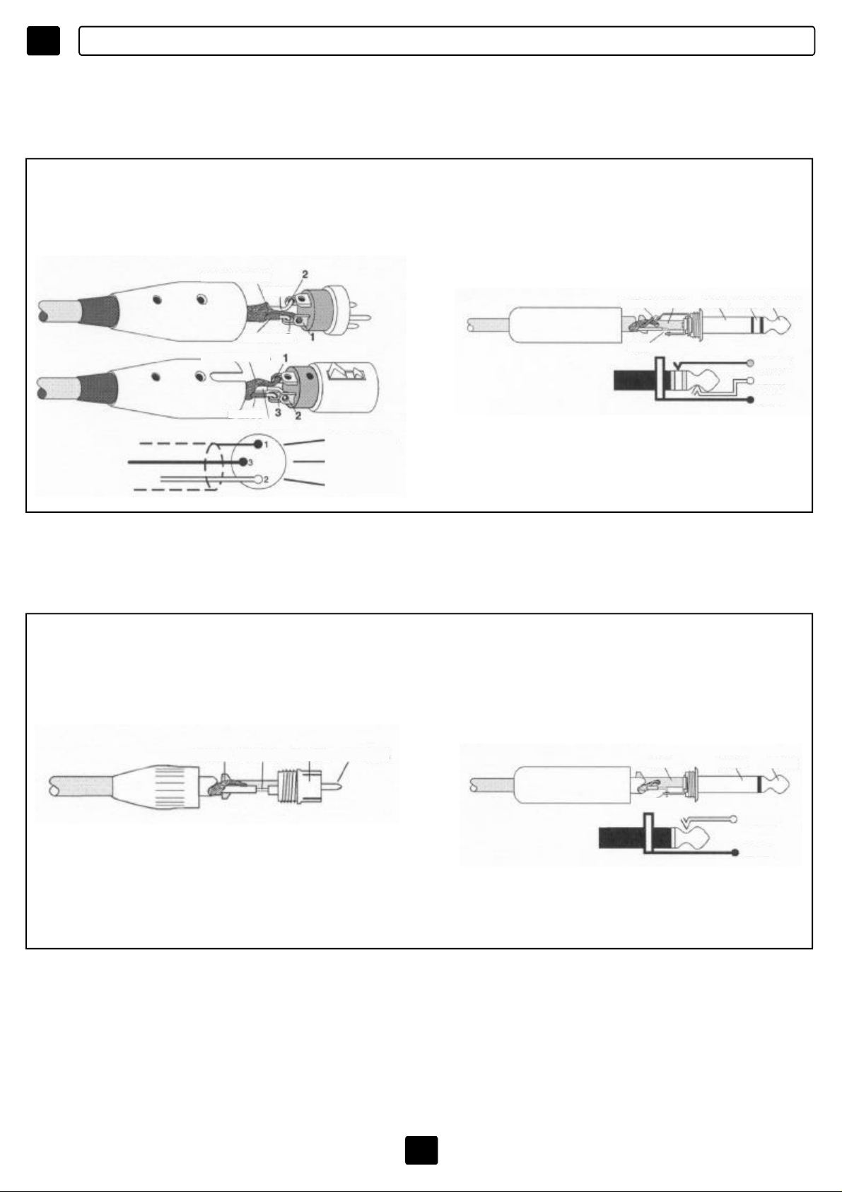
D
ANSCHLUSSBEISPIELE
EINGÄNGE
SYMMETRISCHEQUELLE(SteckverbinderXLR) SYMMETRISCHEQUELLE
(JackTRS/Spitze-Ring-Basis)
SHIELD
HOT
RING SHIELD TIPRINGSLEEVE
COLD
SHIELD
COLD
UNSYMMETRISCHEQUELLE
(SteckverbinderRCA)
HOT
SHIELD
COLD
HOT
TIP
RING
TIP
SHIELD
SHIELD=SCHERMATURA
TIP=HOT(+)
RING=COLD(-)
UNSYMMETRISCHEQUELLE
(JackTS/Spitze-Basis)
SHIELD TIP TIPSHIELD
SLEEVE=SHIELD
TIP=HOT(+)
65
SHIELD SHIELD
TIP
SLEEVE=SHIELD
TIP=HOT(+)
TIP
TIP
SHIELD
Page 67
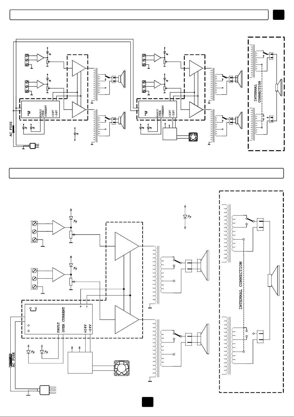
DBLOCKSCHEMA
+15V
230V
115V
AMP1
+
-
+15V
AMP2
+
-
ACPOWER
85-264V
VOLUME
VOLUME
+ -
INPUT
HOT
COLD
SHIELD
INPUT
HOT
COLD
SHIELD
PWRSUPPLY
AMP1
+15V +15V
OC FAULT
MPU4060/4120
*
120Wmod4120
AMP
1
*
60W
AMP
*
60W
AMP
+15V
PWR
-15V
100V
70V
50V
0V
100V
70V
50V
0V
OUT
OUT
+15V
230V
115V
AMP3
+
-
AMP4
+
-
VOLUME
+15V
VOLUME
+15V
-15V
PWR
SUPPLY
+ -
AMP
2
*
60W
AMP
*
60W
AMP
+V
-V
FAN
100V
70V
50V
0V
100V
70V
50V
0V
OUT
OUT
+
-
+
-
INPUT
HOT
COLD
SHIELD
+
-
+
-
INPUT
HOT
COLD
SHIELD
PWRSUPPLY
AMP2
+15V +15V
OC FAULT
100V
100V
70V
50V
70V
50V
0V
OUT
+
-
0V
OUT
+
-
SUM
MPU2120
INPUT
HOT
COLD
SHIELD
INPUT
HOT
COLD
SHIELD
PWRSUPPLY
AMPLIFIER
115V
+15V +15V
OC
230V
FAULT
AMP1
+
-
AMP2
+
-
+15V
+15V
+15V
VOLUME
VOLUME
-15V
POWER
SUPPLY
+V
-V
AMPLIFIER
120W
AMP
120W
AMP
100V
70V
50V
0V
100V
70V
50V
0V
+15V
-15V
OUT
OUT
PWR
+
-
+
-
100V
70V
50V
0V
100V
70V
50V
0V
SUM
OUT
+
-
OUT
+
-
ACPOWER
85-264V
3
FAN
66
Page 68
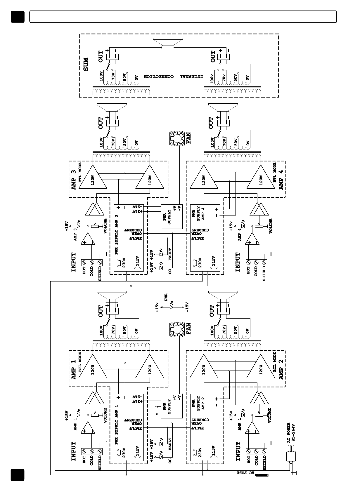
D BLOCKSCHEMA MPU4240
67
Page 69

DTECHNISCHEDATEN
68
Page 70

E
ÍNDICE
ÍNDICE-INTRODUCCIÓN
PRECAUCIONES-INSTALACIÓN
INSTRUCCIONESDESEGURIDADIMPORTANTES
CONEXIONES
PANELANTERIOR
PANELPOSTERIOR
MODODEUSO
TENSIÓNDEALIMENTACIÓN
SALIDAS
ENTRADAS
ESQUEMAFUNCIONAL
ESPECIFICACIONESTÉCNICAS
69
70
71
72-73
74
75
76-77-78-79
80
81
82
83-84
85
INTRODUCCIÓN
Paraoptimizarlarelaciónentrelasinversionesylasprestaciones,hoyendíatantolos
instaladorescomolosusuariosfinalespidenalaindustriasistemascadavezmás
completosyversátiles,capacesderesponder,consusfuncionesytecnologías,alas
modernasexigenciasdedistribuciónsonora.
Unainstalacióncreadaconestasindicacionesdebedisponerdeunapotenciasuficiente
comoparasonorizardistintasáreas,unnúmeroreducidodecomponentes,practicidadde
ensamblaje,rendimientodeejercicio,prestacioneselevadasyconstantes.
FBTElettronicaS.p.A.,alinterpretaryadelantarestasnecesidades,hacreadounanueva
líneadeamplificadores:laserieincluyelosmodelos
MPUMPU2120,MPU4060,MPU
4120,MPU4240.
Setratadeunidadesdepotenciamonobloquecondosocuatroacabados,salidascon
transformadoresdelíneade70Vy100Vquepuedentrabajarenmodalidadestéreoo
“suma”condosposiblesconfiguraciones,unaparacadaunidaddepotencia.
Respuestaenfrecuenciadesde40Hzhasta20kHz,filtrointernodepasoaltode40Hz,
proteccióntérmicaycortocircuitos;enelpanelfrontal,indicacionesluminosasdela
modalidaddetrabajoydelapresenciadeaverías,ajustedelosvolúmenesenelpanel
posterior.
69
Page 71
ATENCIÓN
RIESGODESHOCKELÈCTRICO
NOABRIR
!
UK
E
PARAEVITARCUALQUIERRIESGODESHOCKELÉCTRICOEVITENABRIRLATAPA
!
NOUTILICENUTENSILIOSMECÁNICOSENSUINTERIOR
CONTACTENCONUNCENTRODEASISTENCIACUALIFICADO
PARAEVITARELRIESGODEINCENDIOODESHOCKELÉCTRICO
EVITENEXPONERELAPARATOALALLUVIAOALAHUMEDAD
Estesímboloindica,dondeaparece,lapresenciadeuna
tensiónpeligrosanoaisladaensuinterior:elvoltajepuede
sersuficientecomopararepresentarunpeligrode
descargaeléctrica.
Estesímboloindica,dondeaparece,lapresenciade
importantesinstruccionesdeusoydemantenimientoen
ladocumentaciónadjunta,lesrogamosqueconsultenel
manual.
PRECAUCIONES
ºParagarantizarunaventilaciónsuficiente,esnecesariodisponerdeunadistanciamínima
deaproximadamente30cmentodoslosladosdelaparato.
ºNoimpidanlaventilacióntapandolosorificiosdeventilaciónconobjetoscomoperiódicos,
manteles,cortinas,etc.
ºNoacerquenalaparatoningunafuenteconllama,comoporejemplovelas.
ºEvitenlaexposicióndelaparatoalgoteoochorrosdeaguayevitenapoyarencimadel
aparatocualquierobjetoquecontengalíquidos,comoporejemplovasos.
INSTALACIÓN
ºSielaparatoseinstalaraenuncontenedorrack,éstedeberáreunirtodoslosrequisitosde
lanormativaEN60439-1,yenparticularlaparteposteriordebecerrarseconelpanel
correspondiente.
70
Page 72

E MPU4060/4120
1)Leanlasinstrucciones
2)Conservenestasinstrucciones
3)Prestenatenciónatodaslasadvertencias
4)Sigantodaslasinstrucciones
5)Noutilicenestedispositivoenproximidaddeagua
6)Limpienelaparatoconuntraposeco
7)Noobstruyanlosorificiosdeventilación.Lainstalaciónsedeberállevaracabosiguiendo
lasinstruccionesdelfabricante.
8)Noinstalenelaparatoenproximidaddefuentesdecalor,comoporejemploradiadores,
válvulasderegulación,estufasuotrosaparatos(incluidosamplificadores),quepuedan
emanarcalor.
9)Noanulenelobjetivodeseguridaddelastomaspolarizadasocontomadetierra.Las
tomaspolarizadasdisponendedosláminas,unamáslargayotramáscorta.Unatomacon
puestaatierradisponededosláminasyuntercerpolodetierra.Laláminalargaoeltercer
pologarantizanlaseguridaddelusuario.Sielenchufeproporcionadonofueseadecuadoa
latoma,consultenconunelectricistalaposibilidaddesustituirelenchufe.
10)Protejanelcabledealimentaciónparaquenosepiseochafe,especialmenteen
proximidaddeenchufes,alargaderasoenelpuntoenelquesalendelaunidad.
11)Utilicensólolosdispositivosopcionales/accesoriosqueindicael
fabricante.
12)Utilicenexclusivamenteconcarros,soporte,trípodes,lejasotablasque
indiqueelfabricanteoquevendanjuntoalaparato.Encasodeutilizarun
carro,prestenatenciónduranteeldesplazamientoconjuntodelcarroydel
aparato,paraevitarquesevuelqueocasionandogravesdaños.
INSTRUCCIONESDESEGURIDADIMPORTANTES
13)Desenchufenelaparatoencasodetormentaocuandonosevayaautilizarelaparato
durantemuchotiempo.
14)Paralaasistenciatécnica,lesrogamosquesedirijanalpersonalcualificado.La
asistenciatécnicaesnecesariaencasodeaveríadelaparato,porejemplo,sisedetectaran
problemasconelcabledealimentaciónolatoma,vuelcodelíquidosopresenciadeobjetos
enelinteriordelaparato,exposiciónalalluviaoalahumedad,anomalíasde
funcionamientoocaídasdelaparato.
ELAPARATODEBECONECTARSEALAREDELÉCTRICAMEDIANTEUNENCHUFECON
CONEXIÓNATIERRADEPROTECCIÓN.
Esteaparatodisponedeunatomadealimentación;instalenelaparatodeformaqueel
enchufedelcabledealimentaciónseafácilmenteaccesible.
71
Page 73

CONEXIONES
E
!
ºAntesdeinstalarelaparato,compruebequelatensióneléctricaseacorrecta.Conectarel
amplificadorsólocontomasdecorrienteconconexióndemasa.
ºParaevitarcualquierriesgodedescargaeléctrica,evitentocarloscablesdescubiertos
conectadosalasabrazaderasdelamplificadormientrasestéenmarcha.
ºElaparatodeberárecibirlaalimentacióndelatensiónderedunavezterminadastodaslas
conexiones.
ºLASLÍNEASDEALIMENTACIÓNDELOSALTAVOCESSEDEBERÁNREALIZAR
CONLOCABLESENVUELTOSENCUBIERTAPROTECTORA.
1)LÍNEASDEBAJAIMPEDANCIA
-Laimpedanciaequivalentedelosaltavocesconectadosdebeserigualosuperioralaque
figuraenlasabrazaderasdesalidadelamplificador.
2)LÍNEASDETENSIÓNCONSTANTE
-Cadaaltavozdeberádisponerdeuntransformadordelíneaconunatensióndeentrada
igualaladelínea(70,100V)
ºLasumadelaspotenciasdelosaltavocesnodeberáexcederlapotenciadesalidadel
amplificador.
72
Page 74

E
CABLEADODELASENTRADAS
CONEXIONES
CABLEADODELASENTRADAS
1)Paratodaslasconexionesdeentrada,esprecisoutilizarsólocablesblindados.Los
cablesconapantallamientoconpelículaocontrenzadodealtadensidadsonsuperiores.
Loscablesconapantallamientodecablesenespiral,apesardesermuysensibles,se
puedendañarconeltiempoocausarproblemasrelacionadosconelruido.
2)Eviten,enlamedidadeloposible,elusodelíneasdesequilibradas;sinocabeotra
posibilidad,mantenganloscableslomáscortosposibles.
3)Antesdecambiarlosconectoresoloscablesdeentrada,girenenposiciónmínimalos
ajustesdelniveldelosamplificadores(sentidocontrarioalasagujasdelreloj).
4)Antesdemodificarlasconexionesdesalida,girenligeramenteelniveldelos
amplificadoresyapaguelaalimentacióndecorrienteparaminimizarlaposibilidadde
cortocircuitosenlasalida.
SISTEMASDEDIFUSORESDEDISTRIBUCIÓN
Lossistemasdedifusoresdedistribuciónpararadiobúsquedaymúsicasonmuycomunes
enzonascomohoteles,restaurantes,oficinas,escuelas,etc.Enestossistemasse
distribuyenentodaeláreadistintosdifusores.
Estesistemamultispeakerconsisteenunamplificadorocanaldeamplificaciónquepilota
unoovariosaltavocescontransformadores.
Lostransformadoresreducenlatensióndelíneaaunnivelmásbajo,parapoderpilotarlos
difusores,yseconectansobrelaparejadeconductores.Lacombinacióndeltransformador
ydelaltavozenlíneapresentaunaimpedanciamuchomásaltahaciaelamplificadorcon
respectoalcasodeunúnicodifusor,ydeestaformaesposibleañadirvariosaltavocesa
unaúnicalíneadeseñaldepotencia.
100V
73
Típicosistemadedifusoresdedistribución
100V
AMPLIFICADOR
Page 75

CONTROLESYFUNCIONES
PANELANTERIOR
MPU4240/MPU4120/MPU4060/MPU2120
E
2
1
[1-4]AMP1/2/3/4
4
3
AMP2AMP1 OC FAULT AMP4AMP3 OC FAULT
:Siseenciendeelpiloto,indicalapresenciadelaseñalenel
amplificadorcorrespondiente.
2
1
AMPLIFIER3/4AMPLIFIER1/2 PWR
4
3
5
MPU4240FOURCHANNELSPOWERUNIT
[2]OC
:OVERCURRENT_siseenciendeelpiloto,indicaquelacorrienteabsorbidapor
unacarga(yporlotantolapotencia)superalaqueproporcionaysoportalalíneaoquese
haproducidouncortocircuitoenlalínea.
[3]FAULT
:elpilotoencendidopuedeindicarlarupturadeuncomponenteolaintervención
delaproteccióntérmica:puedeocurrirporunexcesodecalor,porsobrecargaoporuna
señaldemasiadoaltaconfrecuenciaaudioelevada.Enestoscasos,paraevitardanosen
loscircuitosdepotencia,laprotecciónintervienesuspendiendomomentáneamentela
amplificación,hastaqueserestablezcanlascondicionesidóneas.
[5]PWR
:indicaquesehaencendidoelsistema.
74
Page 76

E
CONTROLESYFUNCIONES
PANELPOSTERIOR
MPU4240/MPU4120/MPU4060/MPU2120
6 7 8 9 7 8 9 7 8 9 7 8 9
MPU4060
CAUTION
RISKOFELECTRICSHOCK
DONOTOPEN
TOREDUCETHERISKOFELECTRICSHOCKDONOT
REMOVECOVER(ORBACK)NOUSERSERVICEABLE
PARTSINSIDEREFERSERVICINGTOQUALIFIED
SERVICEPERSONNEL
AMPLIFIER1AMPLIFIER4 AMPLIFIER3 AMPLIFIER2
85÷132Vac/T3,15A-250V
170÷264Vac/T1,6A-250V
PowerConsumption250VA
[6]ALIMENTACIÓN
MadeinItaly
H C S
VOLUME OUTINPUT
H C S
VOLUME OUTINPUT
H C S
VOLUME OUTINPUT
:tomaparalaconexiónalaredeléctrica,interruptordeencendidodel
H C S
VOLUME OUTINPUT
sistemayalojamientodelfusibledeproteccióndelcircuitodealimentación.Encasode
averíadelfusible,sedeberásustituirporotroconlasmismascaracterísticaseléctricas.
Paramodificarelvalordelatensióndealimentación,véasepágina80
[7]INPUT
:conectoresdetrespinconbloqueoderoscaquepermitenconectarlasseñales
deentradadelosamplificadores1/2/3/4.
Utilizarsólocablesblindadosevitandoelusodelíneasdesequilibradas(encasocontrario,
mantengaloscableslomáscortosposibles).
Antesde cambiarlosconectoresoloscablesdeentrada,girenenposiciónmínimalos
ajustesdelniveldelosamplificadores.
[8]VOLUMEN
[9]OUT
:Ajustedelniveldesalidadelosamplificadores.
:conectoresdesalidadedosfastonparalaconexióndedifusorescon
transformadordelíneade100V/70V.Esposibleconfigurarloenmodalidadestéreoo
suma.
(véasepágina76-77-78-79)
75
Page 77

MODODEUSO
E
ATENCIÓN
ELCONECTORDESALIDASEHACONECTADOEN100V/42ohm.PARAOBTENERLASDEMÁS
SALIDASDE70V,SEGUIRELESQUEMAQUEFIGURAENLATAPADELAPARATO.PARA
ACCEDERALCONECTOR,QUITARLATAPA.
PREDISPOSICIÓNINTERNA,ACCESIBLEEXTRAENDOLAPARTESUPERIORDELAPARATO
QUEPERMITELACONFIGURACIÓNDELASUNIDADESDEPOTENCIA,COMOFIGURAENEL
DIBUJO.
MODODEUSODELAUNIDADMPU4240
4x240W
100VOUT
FS1 FS2 FS3 FS4
M1 M2 M3 M4
4x240W
70VOUT
0 0 0 0
J1 J16 J6 J17 J9 J18 J12 J19
INPUT INPUT INPUT INPUTOUT OUT OUT OUT
SPEAKERS
100V/240W
O
42OHMMIN.
FS1 FS2 FS3 FS4
M1 M2 M3 M4
0 0 0 0
J1 J16 J6 J17 J9 J18 J12 J19
INPUT INPUT INPUT INPUTOUT OUT OUT OUT
SPEAKERS
70V/240W
O
21OHMMIN.
SPEAKERS
100V/240W
O
42OHMMIN.
SPEAKERS
70V/240W
O
21OHMMIN.
SPEAKERS
100V/240W
O
42OHMMIN.
SPEAKERS
70V/240W
O
21OHMMIN.
SPEAKERS
100V/240W
O
42OHMMIN.
SPEAKERS
70V/240W
O
21OHMMIN.
2x480W
100VOUT
76
FS1 FS2 FS3 FS4
M1 M2 M3 M4
SHIELD
COLD
HOT
0 0 0 0
J1 J16 J6 J17 J9 J18 J12 J19
INPUT INPUT INPUT INPUT
SPEAKERS100V/480W
O
Z=21OHMMIN.
SHIELD
COLD
HOT
INPUT
SPEAKERS100V/480W
O
Z=21OHMMIN.
Page 78
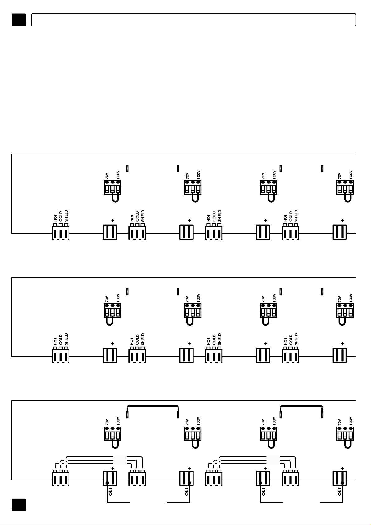
E
MODODEUSO
ATENCIÓN
ELCONECTORDESALIDASEHACONECTADOEN100V/166ohm.PARAOBTENERLAS
DEMÁSSALIDASDE70V,SEGUIRELESQUEMAQUEFIGURAENLATAPADELAPARATO.
PARAACCEDERALCONECTOR,QUITARLATAPA.
PREDISPOSICIÓNINTERNA,ACCESIBLEEXTRAENDOLAPARTESUPERIORDELAPARATO
QUEPERMITELACONFIGURACIÓNDELASUNIDADESDEPOTENCIA,COMOFIGURAENEL
DIBUJO.
MODODEUSODELAUNIDADMPU4060
4x60W
100VOUT
FS1 FS2 FS3 FS4
M1 M2 M3 M4
4x60W
70VOUT
0 0 0 0
J1 J16 J6 J17 J9 J18 J12 J19
OUT OUTINPUTINPUT
SPEAKERS
100V/60W
O
166OHMMIN.
FS1 FS2 FS3 FS4
M1 M2 M3 M4
0 0 0 0
J1 J16 J6 J17 J9 J18 J12 J19
OUT OUTINPUT INPUT
SPEAKERS
70V/60W
O
82OHMMIN.
SPEAKERS
100V/60W
O
166OHMMIN.
SPEAKERS
70V/60W
O
82OHMMIN.
INPUT INPUTOUT OUT
SPEAKERS
100V/60W
O
166OHMMIN.
INPUT INPUTOUT OUT
SPEAKERS
70V/60W
O
82OHMMIN.
SPEAKERS
100V/60W
O
166OHMMIN.
SPEAKERS
70V/60W
O
82OHMMIN.
2x120W
100VOUT
77
FS1 FS2 FS3 FS4
M1 M2 M3 M4
SHIELD
COLD
HOT
0 0 0 0
J1 J16 J6 J17 J9 J18 J12 J19
INPUT INPUTINPUTINPUT
SPEAKERS100V/120W
Z=83OHMMIN.
O
INPUT INPUT
SHIELD
COLD
HOT
INPUT
SPEAKERS100V/120W
O
Z=83OHMMIN.
Page 79
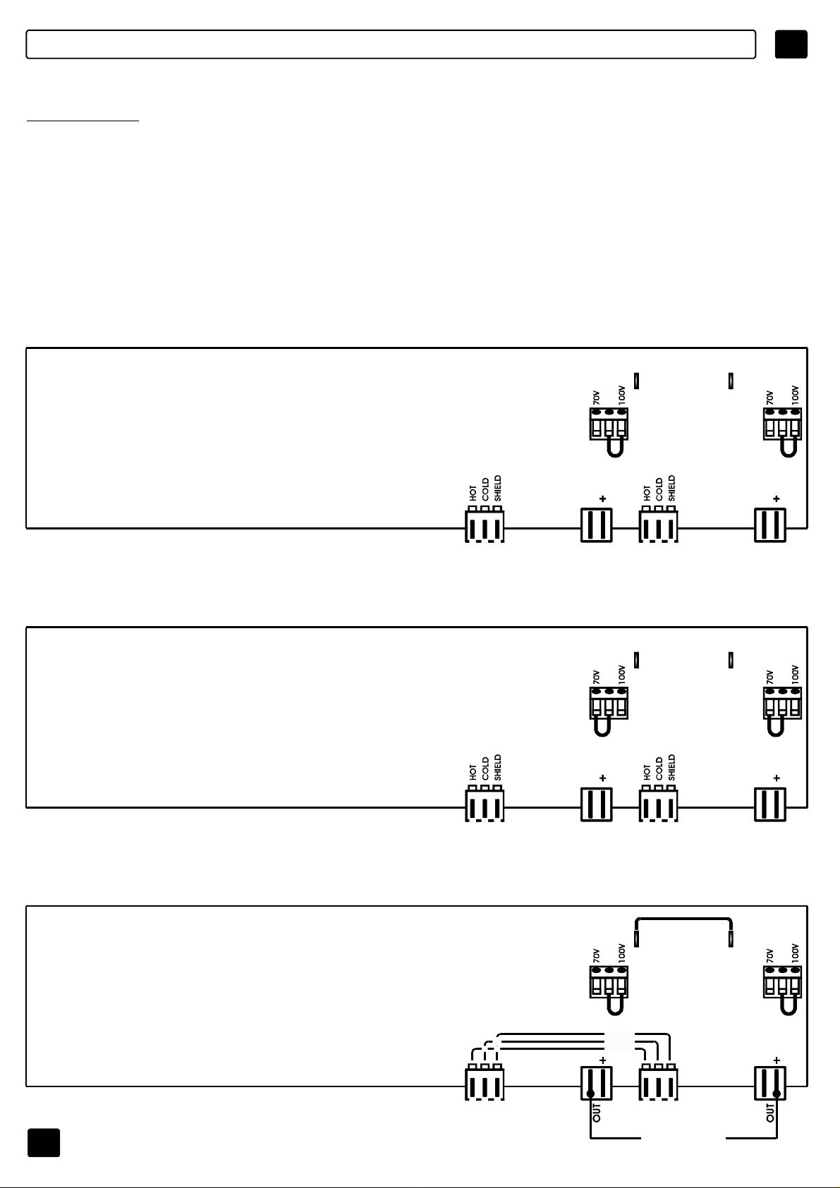
MODODEUSO
E
ATTENZIONE
ILCONNETTOREDIUSCITAÈSTATOCOLLEGATOSU100V/83Ohm.PEROTTENERELE
ALTREUSCITEA70VSEGUIRELOSCHEMARIPORTATOSULCOPERCHIO
DELL’APPARECCHIATURA.PERACCEDEREALCONNETTORERIMUOVEREILCOPERCHIO.
PREDISPOSIZIONEINTERNA,ACCESSIBILERIMUOVENDOLAPARTESUPERIORE
DELL’APPARECCHIO,CHEPERMETTELACONFIGURAZIONEDELLEUNITÀDIPOTENZA
COMEDADISEGNO.
MODODEUSODELAUNIDADMPU2120
2x120W
100VOUT
FS3 FS4
M3 M4
2x120W
70VOUT
0 0
J9 J18 J12 J19
INPUT INPUTOUT OUT
SPEAKERS
100V/120W
O
83OHMMIN.
FS3 FS4
M3 M4
0 0
J9 J18 J12 J19
INPUT INPUTOUT OUT
SPEAKERS
70V/120W
O
41OHMMIN.
SPEAKERS
100V/120W
O
83OHMMIN.
SPEAKERS
70V/120W
O
41OHMMIN.
1x240W
100VOUT
78
FS3 FS4
M3 M4
SHIELD
COLD
HOT
0 0
J9 J18 J12 J19
INPUT INPUT
INPUT
SPEAKERS100V/240W
O
Z=83OHMMIN.
Page 80

E
MODODEUSO
ATENCIÓN
ELCONECTORDESALIDASEHACONECTADOEN100V/83ohm.PARAOBTENERLASDEMÁS
SALIDASDE70V,SEGUIRELESQUEMAQUEFIGURAENLATAPADELAPARATO.PARA
ACCEDERALCONECTOR,QUITARLATAPA.
PREDISPOSICIÓNINTERNA,ACCESIBLEEXTRAENDOLAPARTESUPERIORDELAPARATO
QUEPERMITELACONFIGURACIÓNDELASUNIDADESDEPOTENCIA,COMOFIGURAENEL
DIBUJO.
MODODEUSODELAUNIDADMPU4120
4x120W
100VOUT
4x120W
70VOUT
FS1 FS2 FS3 FS4
M1 M2 M3 M4
0
J1 J16 J6 J17 J9 J18 J12 J19
INPUT INPUT INPUT INPUTOUT OUT OUT OUT
SPEAKERS
100V/120W
O
83OHMMIN.
FS1 FS2 FS3 FS4
M1 M2 M3 M4
0 0 0
SPEAKERS
100V/120W
O
83OHMMIN.
SPEAKERS
100V/120W
O
83OHMMIN.
SPEAKERS
100V/120W
O
83OHMMIN.
2x240W
100VOUT
79
0 0 0 0
J1 J16 J6 J17 J9 J18 J12 J19
INPUT INPUT INPUT INPUTOUT OUT OUT OUT
SPEAKERS
70V/120W
O
41OHMMIN.
FS1 FS2 FS3 FS4
M1 M2 M3 M4
SHIELD
COLD
HOT
0 0 0 0
J1 J16 J6 J17 J9 J18 J12 J19
INPUT INPUT INPUT INPUT
SPEAKERS100V/240W
O
Z=42OHMMIN.
SPEAKERS
70V/120W
O
41OHMMIN.
SPEAKERS
70V/120W
O
41OHMMIN.
SHIELD
COLD
HOT
INPUT
SPEAKERS100V/240W
O
Z=42OHMMIN.
SPEAKERS
70V/120W
O
41OHMMIN.
Page 81

SELECCIONARLATENSIÓNDEALIMENTACIÓN
Cuandoseutilizaelaparatoporprimeravez,compruebenquelatensiónaplicadasea
correcta.
Paraseleccionarelvalordeseadodelatensióndealimentación(85-132Vaco170-264
Vac),signalasinstruccionesquefiguranenlaimagen1.
NOTA:insertarenelalojamientocorrespondiente(véasepágina75)elfusible
adecuadoalatensióndelaalimentaciónseleccionada.
E
230VJUMPER
MPU4240/MPU4120/MPU2120
MPU4060
Im.1
230V
115V
80
Page 82

E CONEXIONES
SALIDAS
ZONE
SPEAKER
100VINPUT
ZONE
SPEAKER
100VINPUT
ZONE
SPEAKER
ZONE
SPEAKER
ZONE
SPEAKER
85÷132Vac/T3,15A-250V
170÷264Vac/T1,6A-250V
PowerConsumption250VA
CAUTION
RISKOFELECTRICSHOCK
DONOTOPEN
TOREDUCETHERISKOFELECTRICSHOCKDONOT
REMOVECOVER(ORBACK)NOUSERSERVICEABLE
PARTSINSIDEREFERSERVICINGTOQUALIFIED
SERVICEPERSONNEL
MadeinItaly
H C S
MPU4060
AMPLIFIER1AMPLIFIER4 AMPLIFIER3 AMPLIFIER2
VOLUME OUTINPUT
H C S
VOLUME OUTINPUT
H C S
VOLUME OUTINPUT
H C S
VOLUME OUTINPUT
81
Page 83

CONEXIONES
ENTRADAS
FUENTEEQUILIBRADA(conectorXLR) FUENTEEQUILIBRADA
(JackTRS/punta-anillo-base)
E
SHIELD
COLD
HOT
BASE=SCHERMATUTA-SHIELD
PUNTA=HOT(+)
ANILLO=COLD(-)
FUENTEDESEQUILIBRADA(connettoreRCA) FUENTEDESEQUILIBRADA
(JackTS/punta-base)
BASE=SCHERMATUTA-SHIELD
PUNTA=HOT(+)
BASE=SCHERMATUTA-SHIELD
PUNTA=HOT(+)
82
Page 84

E
ESQUEMAFUNCIONAL
+15V
230V
115V
AMP1
+
-
+15V
AMP2
+
-
ACPOWER
85-264V
VOLUME
VOLUME
+ -
INPUT
HOT
COLD
SHIELD
INPUT
HOT
COLD
SHIELD
PWRSUPPLY
AMP1
+15V +15V
OC FAULT
MPU4060/4120
*
120Wmod4120
AMP
1
*
60W
AMP
*
60W
AMP
+15V
PWR
-15V
100V
70V
50V
0V
100V
70V
50V
0V
OUT
OUT
+15V
230V
115V
AMP3
+
-
AMP4
+
-
VOLUME
+15V
VOLUME
+15V
-15V
PWR
SUPPLY
+ -
AMP
2
*
60W
AMP
*
60W
AMP
+V
-V
FAN
100V
70V
50V
0V
100V
70V
50V
0V
OUT
OUT
+
-
+
-
INPUT
HOT
COLD
SHIELD
+
-
+
-
INPUT
HOT
COLD
SHIELD
PWRSUPPLY
AMP2
+15V +15V
OC FAULT
100V
100V
70V
50V
70V
50V
0V
OUT
+
-
0V
OUT
+
-
SUM
MPU2120
INPUT
HOT
COLD
SHIELD
INPUT
HOT
COLD
SHIELD
PWRSUPPLY
AMPLIFIER
115V
+15V +15V
OC
230V
FAULT
AMP1
+
-
AMP2
+
-
+15V
+15V
+15V
VOLUME
VOLUME
-15V
POWER
SUPPLY
+V
-V
AMPLIFIER
120W
AMP
120W
AMP
100V
70V
50V
0V
100V
70V
50V
0V
+15V
-15V
OUT
OUT
PWR
+
-
+
-
100V
70V
50V
0V
100V
70V
50V
0V
SUM
OUT
+
-
OUT
+
-
ACPOWER
85-264V
FAN
83
Page 85
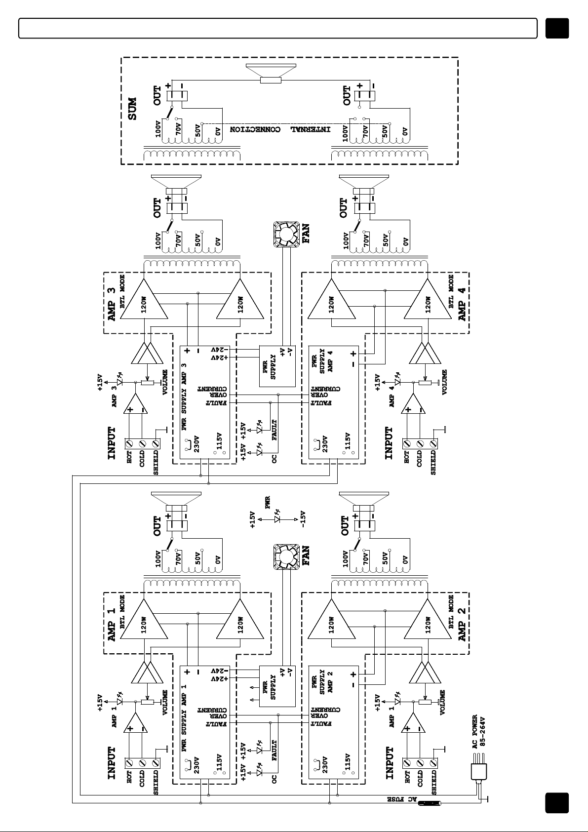
ESQUEMAFUNCIONAL
MPU4240
E
84
Page 86
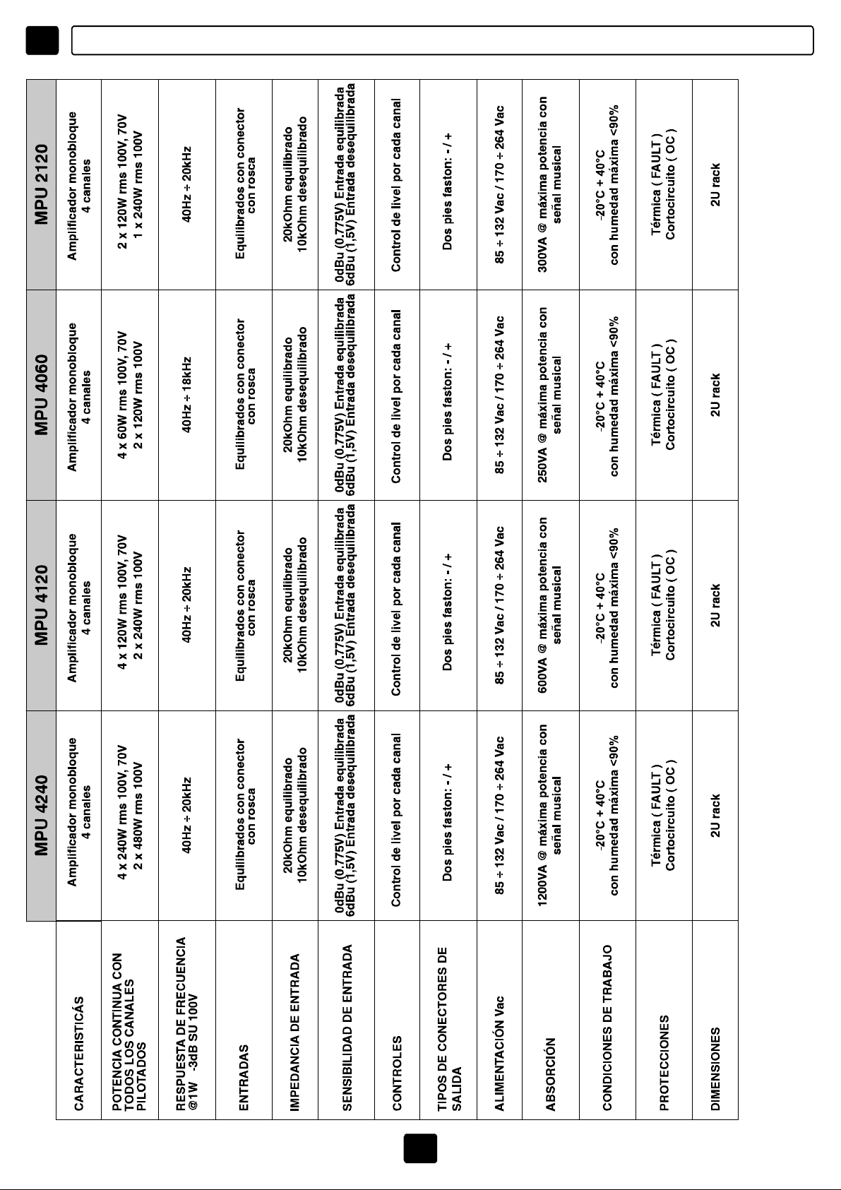
E ESPECIFICACIONESTÉCNICAS
85
Page 87

86
Page 88

CODE:31129
Leinformazionicontenuteinquestomanualesonostatescrupolosamentecontrollate;tuttavialaFBTnon
siassumenessunaresponsabilitàpereventualiinesattezze.LaFBTElettronicaS.p.Asiriservaildirittodi
modificarelecaratteristichetecnicheedestetichedeiprodottiinqualsiasimomentoesenzapreavviso.
Allinformationincludedinthisoperatingmanualhavebeenscrupulouslycontrolled;howeverFBTisnot
responsibleforeventualmistakes.FBTElettronicaS.p.A.hastherighttoamendproductsandspecifications
ADVERTENCIASPARALACORRECTA
ELIMINACIÓNDELPRODUCTOENVIRTUDDELA
DIRECTIVA2002/96/CE.
Finalizadasuvidaútil,elproductonodeberáeliminarse
juntoalosresiduosurbanos,sinoquesedeberádepositar
enloscentrosderecogidaespecíficosquela
administraciónmunicipalponeadisposicióndel
ciudadano,oenlosdistribuidoresqueofreceneste
servicio.Eliminandoseparadamenteunresiduoeléctrico
y/oelectrónico(RAEE)esposibleevitarposibles
consecuenciasnegativasparaelmedioambienteylasalud
quederivendeunaeliminacióninadecuadaypermite
reciclarlosmaterialesdelosquesecomponeparapoder
ahorrarenergíayrecursos.Atalfin,encadaproducto
figuraelsímbolodelcontenedordebasuratachado.
withoutnotice.
Lesinformationscontenuesdanscemanuelontétésoigneusementcontrôlées;toutefoisleconstructeur
n’estpasresponsabled’éventuellesinexactitudes.LaFBTElettronicaS.p.A.s’octroieledroitdemodifier
lesdonnéestechniquesetl’aspectesthètiquedesesproduitssansavispréalable.
AlleinformationenindieserBedienungsanleitungwurdennachbestemWissenundGewissen
zusammengestelltundüberprüft.Daherkönnensiealszuverlässigangesehenwerden.Füreventuelle
FehlerûbernimmtFBTaberkeineHaftung.FBTElettronicaS.p.A.BehältsichdasRechtaufAnderung
derprodukteundSpezifikationenvor.
Lasinformacionescontenidasenestemanualhansidocuidadosamenterevisadas;sinembargo,FBTnoasume
responsabilidadalgunaencasodeposiblesinexactitudes.FBTElettronicaS.p.A.sereservaelderechodemodificarlas
característicastécnicasyestéticasdelosproductosencualquiermomentoysinavisoprevio.
 Loading...