

Page 1

Unità di potenza
I
Power amplifiers
Unité de puissance F
Leistungseinheit D
UK
MPA 5120
ISTRUZIONI PER L’USO
INSTRUCTIONS FOR USE
MPA 5240
MANUEL D’UTILISATION
MPA 5480
FBT ELETTRONICA S.p.A. - Via Paolo Soprani, 1 - ZONA IND. SQUARTABUE - 62019 RECANATI (MC) - ITALY
TEL. 071750591 r.a. - FAX 0717505920 - P.O. BOX 104 - E-mail: info@fbt.it - www.fbt.it
GEbRAUChSANLEITUNG
Page 2

I
INDICE DEI CONTENUTI
UK
TABLE OF CONTENTS
1. AVVERTENZE 1
1.1 Alimentazione e messa a terra 1
1.2 Note di sicurezza 1
1.3 Installazione 1
2. DESCRIZIONE GENERALE
2.1 Pannello frontale 2
2.2 Pannello posteriore 2
3. CONNESSIONI
3.1 Criteri generali 3
3.2 Ingressi/uscite di linea 3
3.3 Ingresso telefonico 3
3.4 Collegamento delle postazioni 3
3.5 Precedenza microfonica e segnale di preavviso 4
3.6 Selettore “CONTROLS” 4
3.7 Uscite di potenza 4
4. USO 5
4.1 Messa in funzione 5
4.2 Controllo di volume principale 5
4.3 Correzione acustica 5
5. NOTE DI SERVIZIO 6
5.1 Sovraccarico e protezione 6
DATI TECNICI 7
3
2
1. WARNINGS 1
1.1 Power supply and earthing 1
1.2 Safety notes 1
1.3 Installation 1
2. GENERAL DESCRIPTION
2.1 Front panel 2
2.2 Rear panel 2
3. CONNECTIONS
3.1 General criteria 3
3.2 Line inputs/outputs 3
3.3 Telephone input 3
3.4 Connection of the microphone stations 4
3.5 Microphone precedence and warning signal 4
3.6 “CONTROLS” selector switch 4
3.7 Power outputs 4
4. USE 5
4.1 Start-up 5
4.2 Master volume control 5
4.3 Acoustic adjustment 5
5. SERVICE NOTES 6
5.1 Overload and protection 6
TECHNICAL DATA 7
3
2
F
1. PRECAUTIONS 8
1.1 Alimentation et mise à la terre 8
1.2 Conseils de securité 8
1.3 Installation 8
2. DESCRIPTION GENERALE
2.1 Panneau frontal 9
2.2 Panneau posterieur 9
3. CONNEXIONS
3.1 Critères generaux 10
3.2 Entrées/sorties de ligne 10
3.3 Entrée téléphoniques 10
3.4 Branchement des postes 10
3.5 Priorité microphonique et signal de préavis 11
3.6 Sélecteur “CONTROLS” 11
3.7 Sorties de puissance 11
4. UTILISATION 12
4.1 Mise en marche 12
4.2 Contrôle de volume principal 12
4.3 Correction acoustique 12
5. NOTICES DE SERVICE 13
5.1 Surcharge et protection 13
DONNEES TECHNIQUES 14
SOMMAIRE
9
10
D
1. HINWEISE 8
1.1 Einspeisung und Erdung 8
1.2 Sicherheitsanweisungen 8
1.3 Installation 8
2. ALLGEMEINE BESCHREIBUNG
2.1 Frontpaneel 9
2.2 Rückpaneel 9
3. ANSCHLÜSSE
3.1 Allgemeine Hinweise 10
3.2 Leitungsein-/-ausgänge 10
3.3 Telefoneingang 10
3.4 Anschluss der Sprechstellen 10
3.5 Mikrofonvorrang und Ankündigungssignal 11
3.6 Wählschalter “CONTROLS” 11
3.7 Leistungausgänge 11
4. GEBRAÜCH 12
4.1 Einschalten 12
4.2 Steuerung der Hauptlautstärke 12
4.3 Tonkorrektur 12
5. SERVICEANWEISUNGEN 13
5.1 Überlastung und Schutz 13
TECHNISCHE EIGENSCHAFTEN 14
INHALTSANGABE
9
10
i
Page 3
I
AVVERTENZE WARNINGS
UK
1.1 ALIMENTAZIONE E MESSA A TERRA
Questi apparecchi sono predisposti per il funzionamento con
tensione di rete a 230 V ± 10% 50/60 Hz. È possibile utilizzare
l’apparecchio anche con una tensione di rete di 120 V ± 10%
50/60 Hz; a tal scopo è necessario portare il selettore (
sul pannello posteriore in posizione “120 V”. Le unità di potenza
della Serie MPA possono anche essere alimentate con una
sorgente esterna di corrente continua con tensione di 24 V che
deve essere applicata, rispettando le polarità, ai relativi terminali
della morsettiera (7). In accordo con le normative di sicurezza,
l’interruttore d’accensione (3) agisce solo sulla tensione di rete. In
dotazione all’apparecchio é fornito un cavo di alimentazione con
filo di terra; il terminale di terra della spina di rete non deve essere
rimosso in alcun caso. Collegare la spina di rete (5) dell’apparecchio
alla rete elettrica utilizzando l’apposito cavo fornito in dotazione;
assicurarsi che la presa di corrente sia dotata di collegamento
di terra a norma di legge. L’apparecchio è protetto da due fusibili
(vedi par. 5.1).
1.2 NOTE DI SICUREZZA
Durante il funzionamento dell’apparecchio è necessario assicurare
un’adeguata ventilazione. Evitare di racchiudere l’apparecchio in un
mobile privo di aerazione o di ostruire le fessure di ventilazione ed
in particolare la presa d’aria laterale della ventola di raffreddamento.
Evitare inoltre di tenere l’apparecchio in prossimità di sorgenti di
calore. Si consiglia di interporre un pannello di aerazione tra un
apparecchio e l’altro. Ogni intervento all’interno dell’apparecchio,
quale la selezione di alcuni modi d’uso o la sostituzione di fusibili,
deve essere effettuato solo da personale specializzato: la rimozione
del coperchio rende accessibili parti con rischio di scosse elettriche.
Prima di rimuovere il coperchio accertarsi sempre che il cavo
di rete sia staccato. Nel caso di accidentale caduta di liquidi
sull’apparecchio, staccare immediatamente la spina di rete ed
interpellare il centro di assistenza FBT più vicino. La connessione
di telaio (
funzione di schermatura dei segnali a basso livello: questa presa
non deve essere utilizzata per il collegamento di sicurezza del
telaio alla terra.
6) consente di collegare altre apparecchiature per la sola
19) posto
1.1 POWER SUPPLY AND EARTHING
This equipment is designed for use with a mains voltage of
230 V ± 10% 50/60 Hz. It is also possible to use the equipment with
a mains voltage of 120 V ± 10% 50/60 Hz; to do this it is necessary
to position the rear-panel selector switch (19) on “120 V”.
The amplifiers of the MPA Series can also be powered by means
of an external DC power supply with a voltage of 24V, which has
to be applied to the appropriate terminals on the terminal strip (7)
paying attention to the correct polarity. As required under safety
regulations, the ON/OFF switch (3) only controls the mains voltage.
The equipment is supplied with its own power-supply cable, which
is equipped with an earthing wire. The earth terminal of the mains
plug should never be removed under any circumstances. Connect
the mains plug (5) of the equipment to the power mains using the
cable included in the supply. Make sure that the power outlet is
equipped with a connection to earth in accordance with the law.
The equipment is protected by two fuses (vedi par. 5.1).
1.2 SAFETY NOTES
While the equipment is working, it is necessary to provide adequate
ventilation. Do not close the equipment in a cabinet without
ventilation. Do not obstruct the ventilation slits and particularly not
the lateral intake of the cooling fan. Do not keep the equipment in
the vicinity of sources of heat. It is recommended that you place
a ventilation panel between one piece of equipment and the next.
Any activities inside the apparatus, such as selecting some of the
operating modes, the installation of accessories or the replacement
of fuses, must be carried out by specialized personnel only: when the
cover is removed, parts liable to cause electric shocks are exposed.
Before removing the cover, always make sure that the power cord
has been disconnected. In the event that liquid is accidentally spilt
onto the apparatus, disconnect the mains plug immediately and
contact the nearest FBT Service Centre. The chassis connection
(6) may be used to connect other equipment only for the purpose
of shielding the low signals: this socket may not be used to connect
the chassis to earth for safety purposes.
1.3 INSTALLAZIONE
Questo apparecchio è predisposto per il montaggio in mobile rack
19” tramite l’uso di apposito accessorio opzionale.
Avvertenze per lo smaltimento del prodotto ai sensi
della Direttiva Europea 2002/96/EC Alla fine della sua
vita utile il prodotto non deve essere smaltito insieme
ai rifiuti urbani, ma deve essere consegnato presso gli
appositi centri di raccolta differenziata predisposti dalle
amministrazioni comunali, oppure presso i rivenditori
che forniscono questo servizio. Smaltire separatamente un rifiuto
elettrico e/o elettronico (RAEE) consente di evitare possibili
conseguenze negative per l’ambiente e per la salute derivanti da
un suo smaltimento inadeguato e permette di recuperare i materiali
di cui è composto al fine di ottenere un importante risparmio di
energia e di risorse. Su ciascun prodotto è riportato a questo scopo
il marchio del contenitore di spazzatura barrato.
Questo prodotto è conforme alle Direttive della
Comunità Europea sotto le quali lo stesso ricade.
1.3 INSTALLATION
This equipment has provisions for mounting in a 19” rack cabinet
using the appropriate optional accessory.
Important information for correct disposal of the
product in accordance with EC Directive 2002/96/EC
This product must not be disposed of as urban waste at
the end of its working life. It must be taken to a special
waste collection centre licensed by the local authorities
or to a dealer providing this service. Separate disposal
of electric and/or electronic equipment (WEEE) will avoid possible
negative consequences for the environment and for health resulting
from inappropriate disposal, and will enable the constituent materials
to be recovered, with significant savings in energy and resources.
As a reminder of the need to dispose of this equipment separately,
the product is marked with a crossed-out wheeled dustbin.
This product is in keeping with the
relevant European Community Directives.
1
Page 4
I
DESCRIZIONE GENERALE GENERAL DESCRIPTION
UK
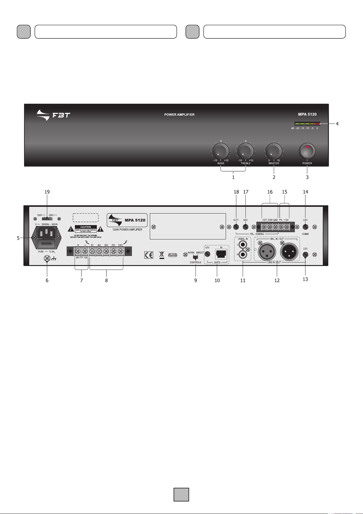
2.1 PANNELLO FRONTALE
1. Controlli di tono.
2. Controllo di volume generale.
3. Interruttore di rete.
4. Visualizzatore del livello d’uscita.
2.1 FRONT PANEL
1. Tone controls.
2. General volume control.
3. Mains switch.
4. Output level indicator.
2.2 PANNELLO POSTERIORE
5. Spina di rete con fusibile incorporato.
6. Connessione telaio.
7. Morsettiera per alimentazione esterna in corrente continua.
8. Morsettiera uscita altoparlanti.
9. Selettore “CONTROLS” (NORMALE/DIRETTO).
10. Ingresso per postazioni e relativa regolazione di livello.
11. Ingresso di linea sbilanciato.
12. Ingresso/uscita di linea bilanciato.
13. Regolazione di livello degli ingressi di linea.
14. Regolazione di livello del segnale di preavviso.
15. Connessioni precedenza.
16. Ingresso emergenza da centralino telefonico.
17. Regolazione di livello dell’ingresso telefonico.
18. Regolazione della soglia d’attivazione
della precedenza telefonica.
19. Selettore della tensione di rete.
2.2 REAR PANEL
5. Mains plug with built-in fuse.
6. Frame connection.
7. Terminal strip for external DC power supply.
8. Terminal strip for loudspeaker output.
9. “CONTROLS” switch (NORMAL/DIRECT).
10. Input for microphone stations and relevant level control.
11. Unbalanced line input.
12. Balanced line input/output.
13. Line inputs level control.
14. Level control of the warning signal (Chime).
15. Precedence connections.
16. Emergency input from PABX.
17. Telephone input level adjustment.
18. Adjustment of the threshold for activating
telephone precedence.
19. Mains voltage selector switch.
2
Page 5
I
CONNESSIONI CONNECTIONS
UK
3.1 CRITERI GENERALI
Per un corretto funzionamento dell’apparecchio è opportuno osservare
alcuni criteri di massima nell’esecuzione dei collegamenti:
n posizionare cavi e microfoni sul mobile dell’apparecchio.
• no
• evitare di stendere le linee di segnale parallele a quelle di rete;
osservare una distanza minima di 30/40 cm.
• posizionare le linee di ingresso e le linee di uscita distanti tra loro.
• posizionare i microfoni al di fuori dell’angolo di radiazione dei
diffusori sonori per evitare il fenomeno di reazione acustica (effetto
Larsen).
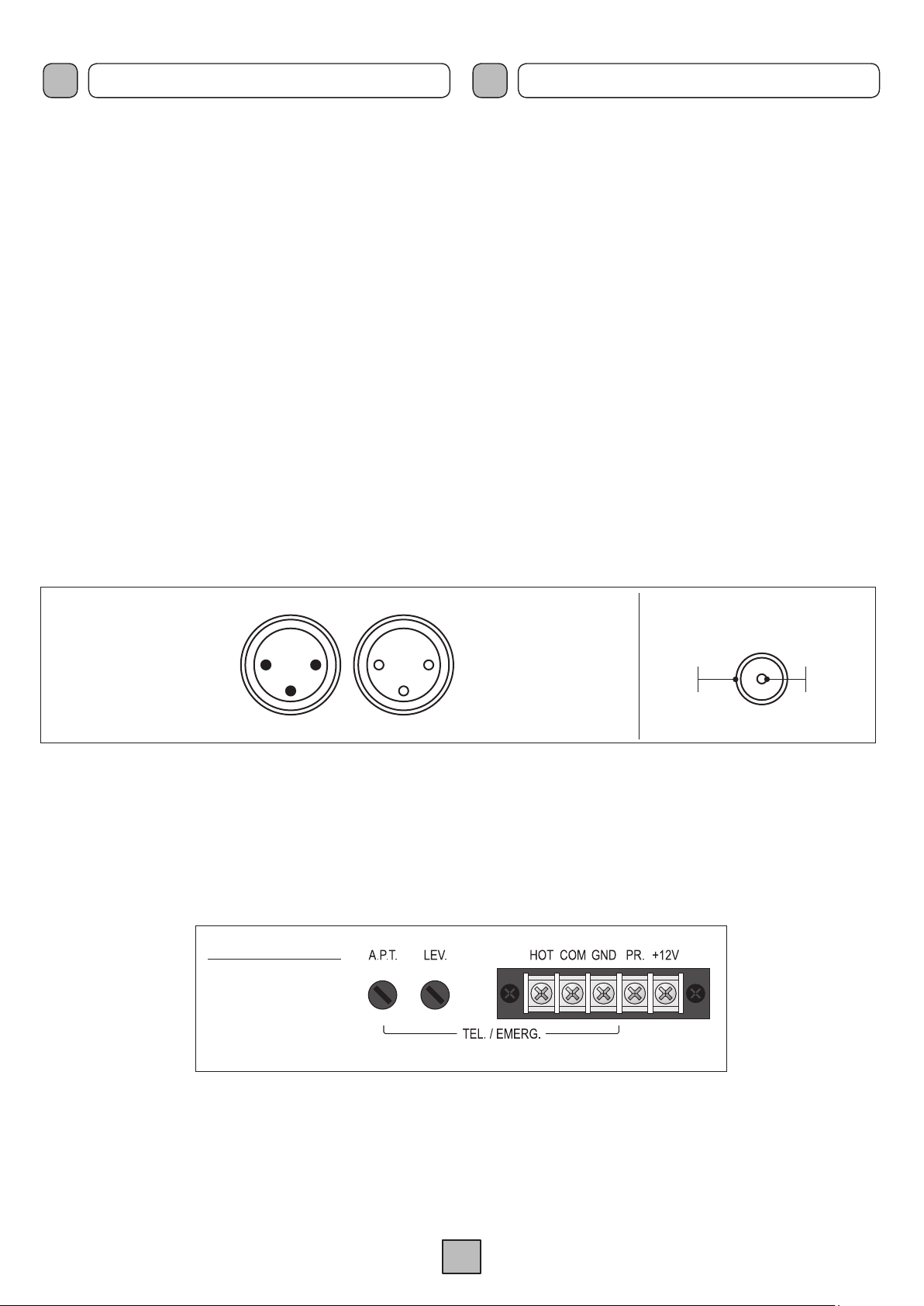
3.2 INGRESSI/USCITE DI LINEA
Sul pannello posteriore dell’apparecchio è disponibile l’ingresso/
uscita di linea bilanciato BAL. IN/OUT
(12) dell’unità di potenza:
per il collegamento sono disponibili, a seconda delle esigenze, una
presa XLR femmina ed una XLR maschio. Inoltre, è disponibile un
ingresso sbilanciato UNBAL. IN (11) con una doppia presa phono
stereo. Il livello di entrambe le tipologie di presa è regolabile tramite
l’apposito trimmer
LEVEL (13). La spina riporta lo stesso segnale
disponibile alla presa, per un facile collegamento in cascata tra più
unità di potenza. Lo stadio d’ingresso è di tipo bilanciato, per cui è
possibile effettuare collegamenti sia di tipo bilanciato che sbilanciato.
La doppia presa phono è invece solo ingresso ed il segnale applicato
è in miscelazione diretta a quello presente sulla presa BAL.IN/OUT.
La figura 3.2.1 riporta le connessioni.
3.1 GENERAL CRITERIA
For proper unit operation, use the following instructions when making
the connections:
• Do not place cables or microphones on the unit cabinet;
• Do not lay signal lines parallel to power lines; ensure a minimum
distance of 30/40 cm between them;
• Keep input lines and the output lines far apart;
• Keep the microphones outside the operating span of the speakers
to avoid acoustic feedback (Larsen effect).
3.2 LINE INPUTS/OUTPUTS
A balanced line input/output (BAL. IN/OUT) is available on the rear
panel of the booster (
12). Depending on requirements, a female
XLR socket and a male XLR plug are available. An unbalanced
input (UNBAL. IN) with a double stereo phono socket is also
available (11). The levels of both these sockets can be adjusted
by means of the
LEVEL trimmer (13). The plug relays the same
signal to the socket, for enabling easy cascade connection of
several boosters. The input stage is of the balanced type, so
that both balanced and unbalanced connections are possible.
The double photo socket, on the other hand, is only an input,
and the signal applied is mixed directly with the one on the BAL.
IN/OUT socket.
Figure 3.2.1 shows the connections.
Collegamento BILANCIATO
1 Schermo
2 Segnale (lato caldo)
3 Segnale (lato freddo)
Collegamento SBILANCIATO
1 Schermo e massa
2 Segnale
3 Schermo e massa
12
3
12
3
3.3 INGRESSO TELEFONICO
L’apparecchio è predisposto per il collegamento ad un sistema
telefonico tramite la morsettiera
TEL./EMERG. (16). Tale ingresso
è bilanciato a trasformatore, possiede un proprio controllo di livello
- LEV. (17) - e di regolazione della soglia d’intervento - A.P.T. (18)
- ed è dotato di circuito VOX per la diffusione dei messaggi con
priorità più elevata rispetto a qualsiasi altro ingresso.
TEL./EMERG.
HOT ingresso (lato caldo)
input (hot side)
COM ingresso (lato freddo)
input (cold side)
GND massa e schermo
GND and shield
BALANCED
1 Shield
2 Signal (hot side)
3 Signal (cold side)
UNBALANCED
1 Shield and GND
2 Signal
3 Shield and GND
connection
connection
Collegamento SBILANCIATO
UNBALANCED connection
Schermo
Shield
Segnale
Signal
Fig. 3.2.1
3.3 TELEPHONE INPUT
The equipment has provisions for connection to a telephone system
by means of the
TEL./EMERG. terminal strip (16). This input is
balanced with a transformer, has its own level control - LEV. (17)
– and the activation threshold can be controlled - A.P.T. (18). It has
a VOX circuit for broadcasting messages with a higher priority than
any other input.
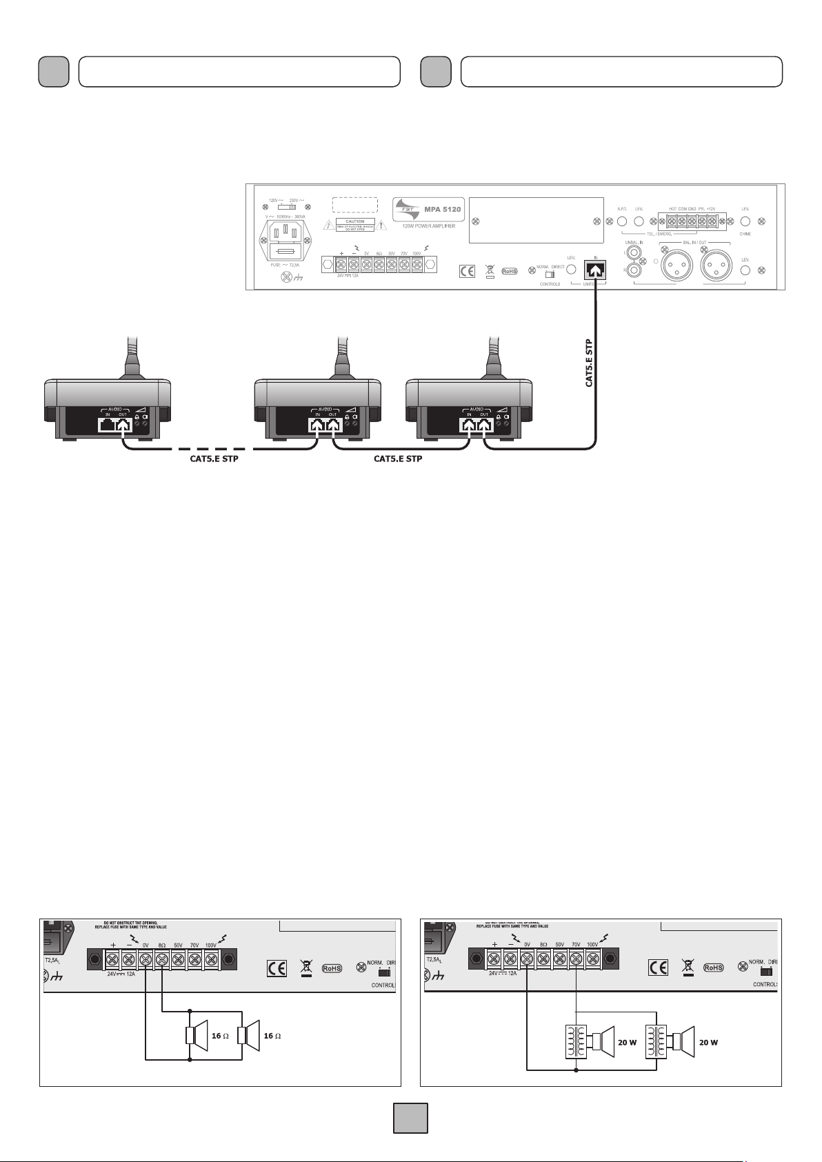
3.4 COLLEGAMENTO DELLE POSTAZIONI
A
gli amplificatori della Serie MPA possono essere collegate in
modo semplice e veloce le postazioni microfoniche preamplificate
MBT 1101; esse sono caratterizzate entrambe da un microfono
elettrete. Per il colle
gament o di questi due modelli, è
INDISPENSABILE utilizzare dei cavi STP CAT5.E (schermati).
Fig. 3.3.1
3.4 CONNECTION OF THE MICROPHONE STATIONS
The MBT 1101 pre-amplified microphone stations can be connected
to amplifiers of the
They both feature electret microphones.
MPA range easily and rapidly.
It is ESSENTIAL to use
shielded cables of the STP CAT5.E type for connecting this
station.
3
Page 6
I
CONNESSIONI CONNECTIONS
UK
L’amplificatore è in grado di alimentare autonomamente fino
a 6 basi: per la gestione di un numero superiore di basi ed altre
informazioni riguardo alle postazioni, fare riferimento al relativo
manuale d’istruzioni.
3.5 PRECEDENZA MICROFONICA E SEGNALE DI PREAVVISO
Chiudendo i contatti della morsettiera (15) viene ammutolito il segnale
presente alle prese
del contatto genera un segnale di preavviso a due toni (CHIME). É
possibile modificare il livello del segnale di preavviso agendo sul
relativo trimmer
din-don (disinseribile) è integrato: nel caso si decida di utilizzare
questa funzione, è necessario disabilitare il din-don dell’amplificatore
portando il controllo
LINE IN/OUT (12) e UNBAL.IN (11); la chiusura
LEV. (14). Nelle postazioni, il segnale di preavviso
LEV. (14) al minimo.
The amplifier is capable of powering up to 6 bases on its own.
To manage a higher number of bases and for further information
concerning stations, consult the appropriate instruction manual.
Fig. 3.4.1
3.5 MICROPHONE PRECEDENCE AND WARNING SIGNAL
If the contacts of the terminal strip (15) are closed, the signal on the
LINE IN/OUT (12) and UNBAL.IN (11) sockets is muted; closing the
contact causes a two-tone warning signal (CHIME) to be generated.
It is possible to change the level of the warning signal by means of
the appropriate
be switched off) is built into the stations. If you decide to use this
function, you must disable the chime of the amplifier by setting the
LEV. control (14) to its lowest.
LEV trimmer (14). The warning chime (which can
3.6 SELETTORE “CONTROLS”
È possibile disabilitare le regolazioni frontali TREBLE, BASS e
MASTER spostando il selettore CONTROLS (9) in posizione
‘DIRECT’; questa funzione permette di evitare, in caso d’emergenza,
che i livelli impostati tramite trimmer sul pannello posteriore vengano
modificati accidentalmente. Per riattivare i controlli frontali è
sufficiente riportare l’interruttore in posizione ‘
3.7 USCITE DI POTENZA
Le uscite di potenza per i diffusori sono disponibili sulla morsettiera (
È possibile realizzare un impianto di diffusione sonora utilizzando
sia diffusori a bassa impedenza (fig. 3.7.1), sia diffusori dotati di
traslatore di linea (fig. 3.7.2). In entrambi i casi, il carico complessivo
non deve essere tale da sovraccaricare l’amplificatore: non
applicare cioè diffusori o gruppi di diffusori con impedenza più
bassa di quella nominale della presa alla quale sono collegati.
NORM.’
8).
3.6 “CONTROLS” SELECTOR SWITCH
It is possible to disable the front-panel TREBLE, BASS and
MASTER controls by moving the CONTROLS selector switch (9)
DIRECT’ position. In emergencies, this function prevents the
to the ‘
levels set by means of the trimmers on the rear panel from being
accidentally altered. To re-activate the front-panel controls simply
return the switch to the ‘
3.7 POWER OUTPUTS
The power outputs for the loudspeakers are available on the terminal
8). It is possible to set up a sound-broadcasting system using
strip (
either low-impedance loudspeakers (fig. 3.7.1) or loudspeakers
equipped with a line transformer (fig. 3.7.2). In both cases the overall
load must not be such as to overload the amplifier. This means that
you must not apply loudspeakers or groups of loudspeakers with an
impedance lower than the rated impedance of the socket to which
they are connected.
NORM.’ position.
Fig. 3.7.1
Fig. 3.7.2
4
Page 7

I
CONNESSIONI CONNECTIONS
UK
Si raccomanda inoltre di porre particolare attenzione al calcolo delle
impedenze nel caso si debbano realizzare impianti di diffusione
misti (a bassa impedenza e a tensione costante). In tabella 3.7.3
sono riportati i valori nominali di tensione ed impedenza per le
diverse uscite.
Uscita • Output MPA 5120 MPA 5240 MPA 5480
8 W
50 V
70 V
100 V
I
4 .1 MESSA IN FUNZIONE
Prima di mettere in funzione l’apparecchio accertarsi di avere
realizzato tutte le connessioni necessarie al completamento
dell’impianto e di aver effettuato le impostazioni di funzionamento.
Portare l’interruttore di rete (
regolare il livello d’ascolto tramite i controlli individuali sul posteriore
dell’apparecchio e ritoccare i livelli delle sorgenti sonore per una
corretta equalizzazione dei segnali tramite il controllo di livello (1).
USO USE
3) in posizione ON. Se necessario,
31 V 43,8 V 62 V
20,8 W 10,4 W 5,2 W
40,8
W 20,4 W 10,2 W
83,3 W 41,7 W 20,8 W
It is also necessary to pay particular attention to calculating the
impedance values if mixed broadcasting systems (low impedance
and constant voltage) are to be set up. Table 3.7.3 shows voltage
and impedance rated values for the various outputs.
Tab. 3.7.3
UK
4 .1 START-UP
Prima di mettere in funzione l’apparecchio accertarsi di avere
realizzato tutte le connessioni necessarie al completamento
dell’impianto e di aver effettuato le impostazioni di funzionamento.
Portare l’interruttore di rete (
the sound level by means of the individual controls on the rear of
the equipment and adjust the levels of the audio sources for correct
equalisation of the signals by means of the level control (1).
3) in posizione ON. If necessary, adjust
4.2 CONTROLLO DI VOLUME PRINCIPALE
Il controllo di volume principale
complessivo del segnale d’uscita, derivato dalla miscelazione dei
vari segnali di ingresso. Per ottenere in uscita un segnale privo di
distorsione, si raccomanda di controllare che sull’indicatore del
livello di uscita (4) non si accenda la spia di colore rosso (0 dB)
o, comunque, che ciò avvenga saltuariamente; in caso contrario, è
necessario diminuire il livello di uscita agendo sul comando (2). La
potenza di uscita nominale è segnalata dall’accensione della spia
luminosa rossa (0 dB).
4.3 CORREZIONE ACUSTICA
I controlli BASS e TREBLE (
uscita derivato dalla miscelazione dei vari segnali di ingresso.
• Controllo toni bassi (BASS)
Il controllo BASS regola le prestazioni dell’amplificatore alle basse
frequenze. La posizione di centro, indicata dallo “0”, fornisce una
risposta lineare; per avere una esaltazione delle frequenze basse
ruotare la manopola in senso ORARIO. Utilizzando diffusori a tromba
è opportuno tramite il comando BASS, attenuare le frequenze basse;
un eccessivo livello delle basse frequenze potrebbe danneggiare
la membrana del diffusore.
• Controllo toni acuti (TREBLE)
Il controllo TREBLE regola le prestazioni acustiche dell’amplificatore
alle alte frequenze. La posizione di centro, indicata dallo “0”, fornisce
una risposta di tipo lineare; per avere una esaltazione delle frequenze
alte ruotare la monopola in senso ORARIO. L’attenuazione dei toni
acuti è utlie per minimizzare un eccessivo livello di fruscio o per
rendere più dolci suoni particolarmente sibilanti.
MASTER (2) regola il livello
1) modificano la tonalità del segnale di
4.2 MASTER VOLUME CONTROL
The
MASTER volume control (2) adjusts the output signal overall
level as generated by mixing different input signals.
To obtain a flutter-free output signal, check that the red LED indicator
(0 dB) on the output level indicator (4) is not on, or at any rate that
it does not light up frequently; otherwise, the output level should be
reduced by the control (2). The rated output power is reached when
the red LED indicator (0 dB) lights up.
4.3 ACOUSTIC ADJUSTMENT
The BASS and TREBLE controls (
generated by mixing the different input signals.
• Bass control (BASS)
The BASS control adjusts the amplifier performance at low
frequencies. The center position “0”. provides a linear response. To
emphasize low frequencies, turn the knob clockwise; to attenuate
them, turn the knob CLOCKWISE. When horn-type speakers are
used, low frequencies should be attenuated by means of the BASS
control. An excessive low frequency level could damage the speaker
diaphragm.
• Treble control (TREBLE)
The TREBLE control adjusts the amplifier performance at high
frequencies. The center position “0” provides a linear response.
To emphasize high frequencies, turn the knob clockwise; to attenuate
them, turn the knob CLOCKWISE. Attenuation of the treble tones
is useful for minimising and excessive level of rustling or in order
to soften hissing sounds.
1) adjust the output signal tone
5
Page 8

I
NOTE DI SERVIZIO SERVICE NOTES
UK
5.1 SOVRACCARICO E PROTEZIONE
Applicare un valore di impedenza di carico inferiore a quella
nominale significa richiedere all’apparecchio una potenza superiore
a quella erogabile con continuità. Questo potrebbe portare al
danneggiamento degli stadi finali di potenza e dei trasformatori di
alimentazione e di uscita. Per non incorrere in questi inconvenienti
gli amplificatori della Serie
di circuiti e dispositivi di protezione contro i sovraccarichi ed i
cortocircuiti:
• circuito limitatore di picco della corrente di uscita: il suo intervento
è istantaneo ed agisce tipicamente nel caso di sovraccarico.
• interruttore termico posto all’interno del trasformatore
d’alimentazione: interrompe l’alimentazione primaria nel
caso di eccessivo surriscaldamento del trasformatore. Il
ripristino è automatico, dopo una fase di raffreddamento del
trasformatore.
• interruttore termico ripristinabile: posto a contatto del dissipatore
dei transistor di potenza, interrompe l’alimentazione dei circuiti
di pilotaggio, e di conseguenza annulla il segnale di uscita, nel
caso in cui la temperatura dei finali raggiunga valori pericolosi.
Il ripristino è automatico non appena la temperatura rientra nel
range di normale funzionamento.
• fusibili di rete - accessibile sulla presa rete (
interna a bassa tensione (accessibile all’interno dell’apparecchio,
sul circuito d’alimentazione): questi dispositivi garantiscono il
blocco immediato del funzionamento dell’amplificatore in caso
di guasto interno dello stesso.
Da segnalare infine che tutti i modelli sono dotati di ventola di
raffreddamento, con controllo automatico della velocità in funzione
della temperatura del dissipatore su cui sono applicati i dispositivi
di potenza.
MPA sono abbondantemente dotati
5) - e di alimentazione
5.1 OVERLOAD AND PROTECTION
Applying a load impedance value lower than the rated loan means
that the equipment is required to supply power in excess of the
capacity that can be delivered with continuity. This could lead
to damage to the final power stages and of the power supply
and output transformers. In order not to incur these upsets, the
amplifiers of the
circuits and devices protecting them against overloads and short
circuits:
• output current peak limiting circuit: this is tripped instantaneously
and its typical function is in the event of overloads.
• Thermal switch inside the power-supply transformer. It cuts off
the primary power in the event of excessive overheating of the
transformer. It resets automatically once the transformer has
cooled down.
• resettable thermal circuit-breaker: this is placed in contact with
the heat sink of the power transistors. It cuts off power to the
driving circuits and therefore cancels the output signal if the
temperature of the end stages reaches hazardous levels. It
resets automatically as soon as the temperature returns to within
the normal operating range.
• mains fuses - accessible on the mains plug (
internal low-voltage power supply (accessible inside the
equipment, on the power supply circuit): these devices stop the
amplifier working immediately in case of internal failure inside
it.
It should be pointed out, lastly, that all the models have cooling
fans, with automatic speed control depending on the temperature
of the heat sink on which the power devices are applied.
MPA Series are equipped with a large number of
5) - and on the
6
Page 9

I
DATI TECNICI TECHNICAL DATA
UK
MODELLO MPA 5120 MPA 5240 MPA 5480 MODEL
Potenza di uscita nominale 120 W 240 W 480 W Rated power output
Uscite a tensione costante 50 - 70 - 100 V Constant voltage outputs
Uscite a bassa impedenza
Distorsione a potenza nominale
8 W
<1% Distorsion at rated power
Low impedance outputs
Controllo toni Tones control
Toni gravi ± 10 dB (100 Hz) Bass tones
Toni acuti ± 10 dB (10 kHz) Treble tones
Ingresso di linea Line input
Sensibilità/impedenza
300 mV/60 k
W
Sensitivity/impedance
Rapporto segnale/disturbo > 77 dB S/N Ratio
Risposta in frequenza 30 ÷ 20.000 Hz (-3 dB) Frequency response
Ingresso IN UNITS IN UNITS input
Sensibilità 1250 mV 320 mV Sensitivity
Rapporto segnale/disturbo > 78 dB S/N Ratio
Risposta in frequenza 30 ÷ 20.000 Hz (-3 dB) Frequency response
Ingresso telefonico Telephone input
Sensibilità/impedenza
120 mV / 6 k
W
Input sensitivity/impedance
Rapporto segnale/disturbo > 75 dB S/N Ratio
Risposta in frequenza 230 ÷ 13.000 Hz (0/-3 dB) Frequency response
Condizioni operative Operating conditions
Alimentazione di rete 230 V
Alimentazione di rete 120 V
Alimentazione in c.c.
(1)
P = 280 W
A = 320 VA
P=260W
A=330 VA
24 V / 6,6 A
(0,2 A @Pout=0W)
P = 535 W
A = 610 VA
P=490W
A=560 VA
24 V / 13,2 A
(0,2 A @Pout=0W)
P = 1160 W
A = 1330 VA
P = 1025 W
A = 1170 VA
24 V / 33 A
(0,8 A @Pout=0W)
230 V Mains power supply
120 V Mains power supply
External DC power supply
(1)
Dimensioni 432 x 88 x 272 mm 432 x 88 x 360 mm Dimensions
Peso 8,2 kg 10,5 kg 16 kg Weight
(1)
±10% 50/60 Hz.
(1)
(1)
7
Page 10

F
PRECAUTIONS HINWEISE
D
1.1 ALIMENTATION ET MISE A LA TERRE
L’appareil est prévu pour être alimenté sur secteur à une tension de
230 V ± 10% 50/60 Hz. Il est possible d’utiliser l’appareil également
avec une tension de secteur de 120 V ±10% 50/60 Hz; pour cela
mettre le sélecteur (
“120 V”. Les amplificateurs de la Série MPA peuvent également
être alimentés par une source externe en courant continu (24V),
laquelle doit être branchée, en veillant à respecter les polarités, aux
bornes correspondantes du bornier (7). Conformément aux normes
de sécurité, l’interrupteur d’allumage (3) est actif uniquement
sur l’alimentation de secteur. L’appareil est fourni avec un câble
d’alimentation pourvu de conducteur de terre; la terminaison de
terre de la fiche de branchement sur secteur ne doit en aucun
cas être retirée. Brancher la fiche (5) de l’appareil au secteur
d’alimentation électrique en utilisant le câble fourni à cet effet et
s’assurer que la prise de secteur est raccordée à la mise à la terre
conformément à la réglementation. L’appareil est protégé par deux
fusibles (voir chap. 5.1).
1.2 CONSEILS DE SECURITE
Pour un bon fonctionnement de l’appareil il est nécessaire d’assurer
une ventilation correcte. Éviter de placer l’appareil dans un meuble
sans aération ou de boucher les fentes de ventilation et en particulier
la prise d’air latérale du ventilateur de refroidissement. Éviter en
outre de placer l’appareil à proximité de sources de chaleur. Il est
recommandé d’intercaler un panneau d’aération entre les appareils.
Toute intervention à l’intérieur de l’appareil, comme la sélection
de certains modes d’emploi, l’application d’accessoires ou la
substitution de fusibles, doit être exclusivement effectuée par un
personnel expert: le retrait du couvercle rend accessibles certaines
parties présentant des risques d’électrocution. Avant d’enlever
le couvercle, contrôler toujours que le cordon d’alimentation est
débranché. En cas de chute accidentelle de liquides sur l’appareil,
débrancher immédiatement la fiche d’alimentation et contacter
le centre d’assistance FBT le plus proche. Il est possible de
relier d’autres appareils à la connexion de masse du châssis (
seulement pour la fonction de protection des signaux à bas niveau:
cette prise ne doit pas être utilisée pour la connexion de sécurité
du châssis à la terre.
19) situé sur le panneau arrière sur la position
6)
1.1 EINSPEISUNG UND ERDUNG
Diese Geräte sind für den Betrieb mit einer Netzspannung
von 230 V ± 10% 50/60 Hz ausgelegt. Es besteht auch die
Möglichkeit, das Gerät mit einer Netzspannung von 120 V ± 10%
50/60 Hz zu betreiben; zu diesem Zweck muss der Wählschalter
(19) an der Rückseite in die Position “120 V” gestellt werden.
Die Verstärker der Serie
Gleichstromspeisung mit einer Spannung von 24V versorgt werden,
die unter Berücksichtigung der Pole an die entsprechenden
Endstücke des Klemmenbretts (
Sicherheitsvorschriften wirkt der Schalter EIN/AUS (3) nur auf
die Netzstromversorgung. Mit dem Gerät wird ein Stromkabel mit
Erdschutzleiter geliefert; das Erdschutz-Endstück des Netzsteckers
darf auf keinen Fall entfernt werden. Stecken Sie den Netzstecker
(5) des Geräts in die Steckdose und versichern Sie sich, dass die
Steckdose einen normentsprechenden Erdleiter besitzt. Das Gerät
ist durch zwei Sicherungen geschützt (siehe Abschnitt 5.1).
1.2 SICHERHEITSANWEISUNGEN
Füreinen fehlerfreien Betriebs des Geräts ist einen geeignete
Belüftung erforderlich. Schließen Sie das Gerät nicht in einem
geschlossenen Schrank ohne Belüftung ein oder verschließen
Sie nicht die Belüftungsschlitze, insbesondere die seitliche
Luftzufuhr des Belüfters. Vermeiden Sie außerdem das Aufstellen
des Geräts in der Nähe von Wärmequellen. Es wird empfohlen
ein Belüftungspaneel zwischen nebeneinander installierten
Geräten zu montieren. Jeder Eingriff im Innern des Geräts,
wie die Wahl einiger Anwendungen, die Montage von Zubehör
oder das Auswechseln von Schmelzsicherungen darf nur von
Fachpersonal vorgenommen werden: die Entfernung des Deckels
legt Komponenten mit Stromschlaggefahr frei. Vor Öffnen des
Deckels ist immer sicherzustellen, daß der Netzstecker abgezogen
ist. Bei versehentlichem Vergießen von Flüssigkeiten auf dem Gerät
muß der Netzstecker unver züglich abgezogen und das nächste
FBT Kundendienstzentrum verständigt werden. Die Verbindung des
Erdschutzleiters des Gehäuses (6) erlaubt auch die Verbindung
anderer Geräte, allerdings mit auschließlicher Schutzfunktion
gegen Niederfrequenzsignale: dieser Anschluß darf nicht für die
Verbindung des Erdschutzleiters verwendet werden.
MPA können auch über eine externe
7) angelegt wird. Gemäß den
1.3 INSTALLATION
Cet appareil est prévu pour être installé dans un meuble rack 19”
en utilisant les appropriés accessoires optionnels.
Recommandations pour l’élimination du produit
conformément à la Directive Européenne 2002/96/
EC Au terme de son utilisation, le produit ne doit pas
être éliminé avec les déchets urbains. L’appareil doit
être remis à l’un des centres de tri sélectif agréés par
l’administration communale ou à un revendeur assurant
ce service. L’élimination différenciée des appareils électroniques
(WEEE) permet non seulement d’éviter les retombées négatives
pour l’environnement et la santé dues à une élimination incorrecte,
mais aussi de récupérer les matériaux qui le composent et permet
ainsi d’effectuer d’importantes économies en termes d’énergie et
de ressources. Pour rappeler l’obligation d’éliminer séparément les
appareils électroniques, le produit porte le symbole d’un caisson
à ordures barré.
Ce produit est conforme aux Directives de la
Communauté Européenne auxquelles il est soumis.
1.3 INSTALLATION
Dieses Gerät ist für die Montage in einem 19”-Rack konzipiert, die
mit Hilfe der optionalen Zubehörteile vorgenommen wird.
Wichtiger Hinweis für die Entsorgung des produkts
in übereinstimmung mit der EG-richtlinie 2002/96/
EC Am Ende seiner Nutzzeit darf das Produkt nicht
zusammen mit dem Siedlungsabfall beseitigt werden,
sondern es muss bei den zu diesem Zweck von den
städtischen Behörden eingerichteten Sammelstellen
oder zu den Fachhändlern, die einen Rücknahmeservice anbieten,
gebracht werden. Die getrennte Entsorgung von Elektro- und
Elektronik-Altgeräten (WEEE - Waste Electric and Electronic
Equipment) vermeidet mögliche negative Auswirkungen auf die
Umwelt und die Gesundheit infolge einer nicht vorschriftsmäßigen
Entsorgung. Zudem wird die Wiederverwertung der Materialen,
aus denen das Gerät besteht, ermöglicht, so dass eine bedeutende
Einsparung an Energie und Ressourcen erzielt wird. Aus diesem
Grund ist das Produkt mit dem Symbol einer durchgestrichenen
Mülltonne gekennzeichnet.
Dieses Produkt entspricht den
diesbezüglichen EU-Richtlinien.
8
Page 11

F
DESCRIPTION GENERALE ALLGEMEINE BESCHREIBUNG
D
2.1 PANNEAU FRONTAL
1. Contrôles tonalités.
2. Contrôle volume général.
3. Interrupteur de secteur.
4. Vu-Meter.
2.1 FRONTPANEEL
1. Klangkontrolle.
2. Kontrolle der allgemeinen Lautstärke.
3. Netzschalter.
4. Vu-Meter.
2.2 PANNEAU POSTERIEUR
5. Fiche de secteur à fusible incorporé.
6. Connexion châssis.
7. Plaquette de connexions pour alimentation externe en c.c.
8. Plaquette de connexions sorties haut-parleurs.
9. Sélecteur “CONTROLS” (NORMAL/DIRECT).
10. Entrée pour postes microphoniques et réglage du niveau.
11. Entrée de ligne non équilibrée.
12. Entrée/sortie de ligne équilibrée.
13. Réglage du niveau des entrées de ligne.
14. Réglage du niveau du signal de préavis.
15. Connexions priorité.
16. Entrée urgence par standard téléphonique.
17. Réglage niveau entrée téléphonique.
18. Réglage du seuil d’activation de la priorité téléphonique.
19. Sélecteur de tension de secteur.
2.2 RÜCKPANEEL
5. Netzstecker mit integrierter Sicherung.
6. Anschluss Rahmen.
7. Klemmenbrett für die ext. Gleichstromversorgung.
8. Klemmenbrett der Lautsprecherausgänge.
9. Wählschalter “CONTROLS” (NORMAL/DIREKT).
10. Eingang für Mikrofonsprechstellen und
entsprechende Stufenregelung.
11. Asymmetrischer Leitungseingang.
12. Symmetrischer Leitungsein-/-ausgang.
13. Stufensteuerung der Leitungseingänge.
14. Stufensteuerung des Ankündigungssignals.
15. Anschlüsse Vorrang und Erzwingen.
16. Eingang für Notmeldung von der Telefonzentrale.
17. Stufenregelung Telefoneingang.
18. Einstellung des Schwellenwerts für die
Aktivierung des Telefonvorrangs.
19. Wählschalter für Netzspannung.
9
Page 12

F
CONNEXIONS ANSCHLÜSSE
D
3.1 CRITERES GENERAUX
Pour un bon fonctionnement de l’appareil il est conseillé de suivre
certains critères généraux pour l’exécution de connexions:
éviter le positionnement de câbles et de microphones sur l’appareil.
•
• éviter de placer les lignes de signal parallèles à celles de réseau;
observer une distance minimum de 30/40 cm.
positionner les lignes d’entrée et sortie séparées les unes des
•
autres.
• positionner les microphones hors de l’angle de radiation des
diffuseurs sonores pour éviter le phénomène de réaction acoustique
(effet Larsen).
3.2 ENTREES/SORTIES DE LIGNE
Une entrée/sortie de ligne équilibrée BAL IN/OUT (12) est présente
sur le panneau arrière de l’unité de puissance: pour la connexion,
il y a, selon les exigences, une prise XLR femelle et une prise XLR
mâle. Il y a en outre une entrée non équilibré UNBAL. IN (11) avec
double prise phono stéréo. Le niveau des deux types de prise est
réglable à l’aide du trimmer
LEVEL (13). La fiche fournit le même
signal disponible sur la prise, pour un branchement en cascade entre
plusieurs unités de puissance. L’étage d’entrée est équilibré, par
conséquent il est possible d’effectuer des raccordement aussi bien
de type équilibré que non équilibré.
La double prise phono est par contre seulement une entrée et le
signal appliqué est en mélange direct avec celui présent sur la
prise BAL.IN/OUT. Les connexions à ces prises sont indiquées à
la Fig. 3.2.1.
3.1 ALLGEMEINE HINWEISE
Für einen korrekten Betrieb des Gerätes müssen folgende Hinweise
für die Anschlüsse beachtet werden:
• Kabel und Mikrophone nie auf das Möbel des Gerätes legen.
• Mikrophonleitungen und Netzkabel nie parallel führen, sondern
einen Mindestabstand von 30-40 cm einhalten.
• Eingangs- und Ausgangsleitungen immer entfernt voneinander
legen.
• Aufstellen von Mikrophonen vor Lautsprechern erzeugt einen
Pfeifton (Larsen-Effekt).
3.2 LEITUNGSEIN-/-AUSGÄNGE
A
n der Rückseite des Geräts ist ein Leitungsein-/-ausgang der
symmetrischen Leitung BAL. IN/OUT (12) der Leistungseinheit
vorhanden: Für den Anschluss stehen, je nach Anforderungen,
eine XLR-Buchse und ein XLR-Stecker zur Verfügung. Außerdem
ist ein asymmetrischer Eingang UNBAL. IN (11) mit einer doppelten
Phono-Stereo-Buchse vorhanden. Die Stufe beider Buchsen kann
mithilfe des entsprechenden Trimmers
LEVEL (13) eingestellt
werden. Für eine einfache Kaskadenschaltung von mehreren
Leistungseinheiten wiederholt der Stecker dasselbe Signal der
Buchse. Die Eingangsstufe ist symmetrisch, so dass es möglich
ist, sowohl symmetrische als auch asymmetrische Verbindungen
herzustellen. Die doppelte Phono-Buchse dient jedoch nur als
Eingang und das eintreffende Signal wird direkt mit dem Signal der
Buchse BAL.IN/OUT gemischt. die Anschlüsse an diese Buchsen
sind in der Abb. Fig. 3.2.1 dargestellt.
Branchement EQUILIBREE
1 Blindage
2 Signal (côté chaud)
3 Signal (côté froid)
Branchement DESEQUILIBREE
1 Blindage et masse
2 Signal
3 Blindage et masse
12
3
12
3
3.3 ENTREE TELEPHONIQUE
L’appareil est prévu pour le raccordement à un système téléphonique
à l’aide du bornier
TEL./EMERG. (16). Cette entrée est équilibrée
sur transformateur et possède un contrôle de niveau - LEV. (17)
- et de réglage du seuil d’intervention - A.P.T. (18) - et est muni d’un
circuit VOX pour la diffusion des messages avec priorité sur toutes
les autres entrées.
TEL./EMERG.
HOT Entrée (côté chaud)
Eingang (warme Seite)
Entrée (côté froid))
COM
Eingang (kalte Seite)
Masse et blindage
GND
Erdung und
Abschirmung
SYMMETRISCHE
1 Abschirmung
2 Signal (warme Seite)
3 Signal (kalte Seite)
ASYMMETRISCHE
1 Abschirmung und Erdung
2 Signal
3 Abschirmung und Erdung
Anschlüsse
Anschlüsse
Branchement DESEQUILIBREE
ASYMMETRISCHE
Blindage
Abschirmung
Anschlüsse
Signal
Fig./Abb 3.2.1
3.3 TELEFONEINGANG
Für den Anschluss an ein Telefonsystem ist das Gerät mit dem
Klemmenanschluss
TEL./EMERG. (16) ausgerüstet. Dieser Eingang
ist mittels eines Transformators symmetriert, besitzt eine eigene
Stufenkontrolle - LEV. (17) – mit Regulierung der Einsatzschwelle
- A.P.T. (18) – und ist mit einer VOX–Schaltung für die Sendung
von Meldungen mit höherer Priorität im Vergleich zu jedem anderen
Eingang ausgerüstet.
3.4 BRANCHEMENT DES POSTES
Les postes microphoniques préamplifiés MBT 1101, tous deux munis
d’un microphone à électret, peuvent être reliés de façon simple et
rapide aux amplificateurs de la Série
MPA. Pour le branchement
de ces deux modèles, il est INDISPENSABLE d’utiliser des
cordons STP CAT5.E (blindés).
Fig./Abb. 3.3.1
3.4 ANSCHLUSS DER SPRECHSTELLEN
An die Verstärker der Serie MPA können die vorverstärkten
Mikrofonsprechstellen MBT 1101 einfach und schnell angeschlossen
werden, die beide über ein Elektretmikrofon verfügen. Für den
Anschluss dieser beiden Modelle ist es UNERLÄSSLICH, STP
CAT5.E (geschirmte Kabel) zu verwenden.
10
Page 13

F
CONNEXIONS ANSCHLÜSSE
D
L’amplificateur peut alimenter jusqu’à 6 bases de façon
autonome: pour la gestion d’un plus grand nombre de bases et
avoir plus d’informations, consulter la notice d’utilisation.
3.5 PRIORITE MICROPHONIQUE ET SIGNAL DE PREAVIS
En fermant les contacts du bornier (
LINE IN/OUT (12) et UNBAL.IN (11) est assourdi; la fermeture
prises
du contact génère un signal de préavis à deux tons (CHIME): il est
possible de modifier le niveau du signal de préavis en intervenant
sur le trimmer
dong (désactivable) est intégré dans les postes: pour utiliser cette
fonction, il faut désactiver le ding-dong de l’amplificateur en plaçant
commande
LEV. correspondant (14). Le signal de préavis ding-
LEV. (14) au minimum.
15), le signal présent sur les
Der Verstärker kann autonom bis zu 6 Sprechstellen einspeisen:
Für die Steuerung einer größeren Anzahl an Sprechstellen und
für weitere Informationen über die Sprechstellen wird auf das
entsprechende Betriebshandbuch verwiesen.
Fig./Abb. 3.4.1
3.5 MIKROFONVORRANG UND ANKÜNDIGUNGSSIGNAL
Bei Schließen der Kontakte des Klemmenbretts (
Signal an den Buchsen
stummgeschaltet; Der Verschluss des Kontakts generiert ein 2-TonAnkündigungssignal (CHIME): Die Stufe des Ankündigungssignals
kann durch Betätigen des entsprechenden Trimmers
werden (14). Das 2-Ton-Ankündigungssignal (abschaltbar) ist in die
Sprechstellen integriert: Falls diese Funktion verwendet werden soll,
muss das 2-Ton-Signal des Verstärkers deaktiviert werden, indem
die Kontrolle
LEV. (14) auf den Mindestwert gestellt wird.
LINE IN/OUT (12) und UNBAL.IN (11)
15) wird das
LEV. verändert
3.6 SELECTEUR “CONTROLS”
Il est possible de désactiver les réglages en façade TREBLE, BASS
MASTER en mettant le sélecteur CONTROLS (9) sur la position
et
‘DIRECT’; cette fonction permet d’éviter, en cas d’urgence, que les
niveaux réglés avec le trimmer sur le panneau arrière ne soient
modifiés accidentellement. Pour réactiver les contrôles en façade,
il suffit de remettre l’interrupteur sur la position ‘
3.7 SORTIES DE PUISSANCE
Les sorties de puissance pour les haut-parleurs sont disponibles
sur le bornier (
sonore en utilisant aussi bien des diffuseurs à basse impédance
(fig. 3.7.1) que des diffuseurs dotés de transformateurs de ligne (fig.
3.7.2). Dans les deux cas, la charge totale ne doit pas surcharger
l’amplificateur: aussi est-il important de ne pas relier de diffuseurs
ni de groupes de diffuseurs d’impédance inférieure à l’impédance
nominale de la prise à laquelle ils sont reliés.
8). Il est possible de réaliser un système de diffusion
NORM.’
3.6 WÄHLSCHALTER “CONTROLS”
Die an der Vorderseite vorhandenen Einstellungen TREBLE, BASS
MASTER können eingestellt werden, indem der Wählschalter
und
CONTROLS (9) in die Position ‘DIRECT’ gesetzt wird; dank dieser
Funktion kann vermieden werden, das die mithilfe des Trimmers
an der Rückseite eingestellten Stufen im Notfall versehentlich
verändert werden. Zur Reaktivierung der vorderseitig vorhandenen
Kontrollen, muss der Schalter lediglich in die Position ‘
gebracht werden.
3.7 LEISTUNGAUSGÄNGE
Die Leistungsausgänge der Lautsprecher sind auf dem Klemmenbrett
(8) installiert. Es können Beschallungsanlagen sowohl durch
Lautsprecher mit niedriger Impedanz (Abb. 3.7.1) als auch durch
Lautsprecher mit Linientransformator (Abb. 3.7.2) aufgebaut
werden. In beiden Fällen darf die Gesamtlast den Verstärker
nicht überbelasten: verwenden Sie keine Lautsprecher oder
Lautsprechergruppen mit einer niedrigeren Impedanz als der
Nennimpedanz der Buchse, an die sie angeschlossen sind.
NORM.’
Fig./Abb. 3.7.1
Fig./Abb. 3.7.2
11
Page 14

F
CONNEXIONS ANSCHLÜSSE
D
Il est recommandé en outre d’accorder une grande attention au
calcul des impédances dans le cas où devraient être réalisées des
installations de diffusion mixtes (à basse impédance et tension
constante). Le tableau 3.7.3 indique les valeurs nominales de
tension et d’impédance pour les différentes sorties.
Sortie • Ausgang MPA 5120 MPA 5240 MPA 5480
8 W
50 V
70 V
100 V
F
4 .1 MISE EN MARCHE
Avant d’allumer l’appareil, s’assurer que tous les branchements
nécessaires à l’installation ont bien été effectués de même que les
configurations de fonctionnement. Placer l’interrupteur d’alimentation
(3) en position ON. Si cela est nécessaire, régler le niveau d’écoute à
l’aide des commandes présentes à l’arrière de l’appareil et réajuster
les niveaux des sources sonores pour une bonne égalisation des
signaux à l’aide de la commande de niveau (1).
UTILISATION GEBRAÜCH
31 V 43,8 V 62 V
20,8 W 10,4 W 5,2 W
40,8
W 20,4 W 10,2 W
83,3 W 41,7 W 20,8 W
Außerdem wird empfohlen, der Berechnung der Impedanz
be sondere Aufm erksamke it zu widmen , wenn gemis chte
Beschallungsanlagen installiert werden sollen (mit niedriger
Impedanz und Gleichspannung). Die Tabelle 3.7.3 enthält eine Liste
der Spannungs- und Impedanznennwerte für die verschiedenen
Ausgänge.
Tab. 3.7.3
D
4 .1 EINSCHALTEN
Vor Einschalten des Geräts muss sichergestellt werden, dass alle
für die komplette Installation der Anlage erforderlichen Anschlüsse
hergestellt und die Betriebseinstellungen vorgenommen wurden.
Den Netzschalter (
die Lautstärke über die einzelnen Regler an der Geräterückseite
eingestellt und die Stufen der Tonquellen zwecks einer korrekten
Signalmischung mithilfe der Stufenkontrollen (1) justiert werden.
3) auf ON schalten. Falls erforderlich, muss
4.2 CONTROLE DE VOLUME PRINCIPAL
Le contrôle
général du signal de sortie, dérivant du mixage des différents
signaux d’entrée. Pour obtenir en sortie un signal sans distorsion, il
est conseillé de contrôler que le voyant rouge (0 dB) de l’indicateur
du niveau de sortie (4) ne s’allume pas ou, tout au plus, que cela
n’ait lieu que de temps à autre; autrement, il faudra diminuer le
niveau de sortie en actionnant la commande (6). La puissance de
sortie nominale est signalée par l’allumage du voyant lumineux
rouge (0 dB).
4.3 CORRECTION ACOUSTIQUE
Les contrôles BASS et TREBLE (
tonalité du signal de sortie dérivant du mixage des différents signaux
d’entrée.
• Contrôle tonalité basses (BASS)
La commande BASS règle les prestations de l’amplificateur pour
les basses fréquences. La position médiane 0 fournit une réponse
de type linéaire; pour avoir une exaltation des fréquences basses,
tourner le bouton en sens horaire. En utilisant des diffuseurs à
pavillon il est conséillé d’atténuer les fréquences basses à l’aide
de la commande BASS; un niveau excessif des basses fréquences
pourrait endommager la membrane du diffuseur.
• Contrôle tonalité aigues (TREBLE)
Le contrôle TREBLE règle les prestations acoustiques de
l’amplificateur pour les hautes fréquences. La position médiane 0
fournit une réponse de type linéaire; pour avoir une exaltation des
fréquences hautes, tourner le bouton en sens horaire.
L’atténuation des tonalités aiguës permet de réduire un niveau de
bruit excessif et d’adoucir les sons particulièrement chuintant.
de volume principal MASTER (2) règle le volume
1) permettent de modifier la
4.2 STEUERUNG DER HAUPTLAUTSTÄRKE
Die Hauptkontrolle der Lautstärke
Gesamtstufe des Ausgangssignals, das aus der Mischung der
verschiedenen Eingangssignale stammt. Um ein Ausgabesignal
ohne Verzerrung zu erhalten, wird empfohlen, zu überprüfen,
ob sich auf dem Ausgangspegelanzeiger (4) nicht die rote
Kontrollampe einschaltet (0 dB) oder ob dies in unregelmäßigen
Abständ en gesc hieht; wenn nicht, ist es notwendig, den
Ausgabepegel durch Betätigung der Steuerung (6) herabzusetzen.
Die Ausgangsnennleistung wird durch das Einschalten die rote
Kontrollampe (0 dB) angezeigt.
4.3 TONKORREKTUR
Die Kontrollen BASS und TREBLE (
signals, das aus der Mischung der verschiedenen Eingangssignale
stammt.
• Tiefenkontrolle (BASS)
Die BASS-Steuerung reguliert die Tonleistung des Verstärkers bei
niedriger Frequenz. Die zentrale Position 0 gibt eine lineare Antwort;
für eineVerstärkung der Niederfrequenzen den Drehknopf im
Uhrzeigersinn drehen. Bei Benutzung trichterförmiger Lautsprecher
ist es angebracht, die niedrigen Frequenzen mit der BASSSteuerung zu dämpfen; übertrieben niedrige Frequenzen könnten
die Membran des Lautsprechers beschädigen.
• Kontrolle hohe töne (TREBLE)
Di
e TREBLE-Steuerung reguliert die Tonabgabe des Verstärkers
bei hoher Frequenz. Die zentrale Position 0 gibt eine lineare
Antwort; für eine Verstärkung der hohen Frequenzen den
Drehknopf im Uhrzeigersinn drehen; für eine Dämpfung der hohen
Frequenzen den Knopf gegen den Uhrzeigersinn drehen. Die
Abschwächung von Hochtönen ist für die Minimierung eines zu hohen
Nebengeräuschpegels hilfreich sowie auch für die Abschwächung
von zu stark pfeifenden Tönen.
MASTER (2) reguliert die
1) ändern den Ton des Ausgang-
12
Page 15

F
NOTICES DE SERVICE SERVICEANWEISUNGEN
D
5.1 SURCHARGE ET PROTECTION
Appliquer une valeur d’impédance de charge inférieure à la valeur
nominale a pour effet de demander à l’appareil une puissance
supérieure à celle disponible en continuité. Dans ce cas, les paliers
terminaux de puissance sont susceptibles d’être endommagés, de
même que les transformateurs d’alimentation et de sortie. Pour
prévenir ce type de problème, les amplificateurs de la Série
sont dotés de nombreux circuits et dispositifs de protection contre
les surcharges et les courts-circuits:
• circuit de limitation des pics de courant de sortie: son intervention
est instantanée en cas de surcharge.
• interrupteur thermique situé à l’intérieur du transformateur
d’alimentation: coupe l’alimentation primaire en cas de surchauffe
excessive du transformateur. La restauration est automatique,
après une phase de refroidissement du transformateur.
• interrupteur thermique à réarmement automatique: installé
au contact du dissipateur des transistors de puissance, il
coupe l’alimentation des circuits de commande et annule par
conséquent le signal de sortie dans le cas où la température
des paliers terminaux attendrait des valeurs dangereuses. Le
réarmement est automatique dès que la température est à
nouveau en deçà de la limite de fonctionnement.
• fusible de secteur - accessible sur la prise de secteur (
fusible d’alimentation interne à basse tension (accessible à
l’intérieur de l’appareil sur le circuit d’alimentation): ces deux
fusibles assurent l’interruption immédiate du fonctionnement de
l’appareil en cas d’anomalie interne.
À signaler enfin que tous les modèles sont munis d’un ventilateur
de refroidissement, avec contrôle automatique de la vitesse en
fonction de la température du dissipateur sur lequel les dispositifs
de puissance sont appliqués.
MPA
5) - et
5.1 ÜBERLASTUNG UND SCHUTZ
Die Verwendung eines niedrigeren Verbraucherimpedanzwertes als
dem des Nennwertes entsprechenden Wertes bedeutet, vom Gerät
eine höhere Leistung als die kontinuierlich lieferbare Leistung zu
verlangen. Dies kann zur Beschädigung der Endleistungsstadien
sowie der Speisungstransformatoren und Ausgangstransformatoren
führen. Um dies zu vermeiden, besitzen die Verstärker der
Serie
MPA eine große Zahl an Sicherungsschaltkreisen und -
vorrichtungen gegen Überlastungen und Kurzschlüsse:
• Schaltkreis für die Stromspitzenbegrenzung am Ausgang: sein
Einsetzen erfolgt unmittelbar, er setzt bei Überlastung ein.
• Thermoschalter in Innern des Einspeisungstransformators:
unterbricht die primäre Einspeisung bei Überhitzung des
Transformators: Die Wiederaufnahme des Betriebs erfolgt nach
einer Phase der Abkühlung des Transformators automatisch.
• Rückstellbarer Wärmeschalter: liegt am Kontakt des Verteilers
der Leistungstransistoren, unterbricht die Versorgung der
Steuerschaltkreise und annulliert dementsprechend das
Ausgangssignal, wenn die Temperatur der Endstufen gefährliche
Werte erreicht. Die Wiederaufnahme erfolgt automatisch
sobald die Temperatur in den Bereich des normalen Betriebs
zurückkehrt.
• Netzsicherungen - Zugang an der Netzbuchse (
Sic h erungen der in ternen Niederspannung s speisung
(Zugang über den Innenraum des Geräts, sie liegen auf dem
Versorgungsschaltkreis): diese Vorrichtungen gewährleisten die
unmittelbare Blockierung des Betriebs des Verstärkers, wenn
in dessen Innern ein Schaden vorhanden ist.
Es wird abschließend darauf hingewiesen, dass alle Modelle
einen Kühlventilator mit automatischer Geschwindigkeitskontrolle
je nach Temperat u r de r W ä rm e ab l ei t e r, an die die
Leistungsverstärker angeschlossen sind, ausgerüstet sind.
5) - und
13
Page 16

F
DONNEES TECHNIQUES TECHNISCHE EIGENSCHAFTEN
D
MODELE MPA 5120 MPA 5240 MPA 5480 MODELL
Puissance nominale de sortie 120 W 240 W 480 W Nominale Ausgangsleistung
Sorties à tension constante 50 - 70 - 100 V Ausgänge bei Gleichspannung
Sorties à basse impédance
Distorsion à la puissance nominale
8 W
<1% Verzerrung bei Nominalleistung
Ausgänge bei niedriger Impedanz
Correction acoustique Tonkorrektur
Tonalité basses ± 10 dB (100 Hz)
Tonalité aigues ± 10 dB (10 kHz)
Tieftöne
Hochtöne
Entrée de ligne Leitungseingang
Sensibilité/impédance
300 mV/60 k
W
Empfindlichkeit/Impedanz
Rapport signal/bruit > 77 dB Verhältnis von Signal/Störung
Réponse en fréquence 30 ÷ 20.000 Hz (-3 dB)
Frequenzgang
Entrée IN UNITS IN UNITS Eingang
Sensibilité 1250 mV 320 mV Empfindlichkeit
Rapport signal/bruit > 78 dB Verhältnis von Signal/Störung
Réponse en fréquence 30 ÷ 20.000 Hz (-3 dB)
Frequenzgang
Entrée téléphonique Telefoneingang
Sensibilité/impédance
120 mV / 6 k
W
Empfindlichkeit/Impedanz
Rapport signal/bruit > 75 dB Verhältnis von Signal/Störung
Réponse en fréquence 230 ÷ 13.000 Hz (0/-3 dB)
Frequenzgang
Conditions de fonctionnement Betriebsbedigungen
Alimentation secteur 230 V
Alimentation secteur 120 V
Alimentation externe en c.c.
Dimensions
(1)
(1)
P = 280 W
A = 320 VA
P=260W
A=330 VA
24 V / 6,6 A
(0,2 A @Pout=0W)
432 x 88 x 272 mm 432 x 88 x 360
P = 535 W
A = 610 VA
P=490W
A=560 VA
24 V / 13,2 A
(0,2 A @Pout=0W)
P = 1160 W
A = 1330 VA
P = 1025 W
A = 1170 VA
24 V / 33 A
(0,8 A @Pout=0W)
mm
230 V Netzspannung
120 V Netzspannung
Externe Gleichstromspeisung
Abmessungen
Poids 8,2 kg 10,5 kg 16 kg Gewicht
(1)
(1)
(1)
±10% 50/60 Hz.
14
Page 17

151617
Page 18

Page 19

Page 20

code: 37482
Le informazioni contenute in questo manuale sono state scrupolosamente controllate; tuttavia FBT non si assume nessuna
responsabilità per eventuali inesattezze. La FBT Elettronica S.p.A. si riserva il diritto di modificare le caratteristiche tecniche
ed estetiche dei prodotti in qualsiasi momento e senza preavviso.
All information included in this operating manual have been scrupolously controlled; however FBT is not responsible for
eventual mistakes. FBT Elettronica S.p.A. has the right to amend products and specifications without notice.
Les information contenues dans ce manuel ont été soigneusement contrôlées; toutefois le constructeur n’est pas responsable
d’éventuelles inexactitudes. La FBT Elettronica S.p.A. s’octroie le droit de modifier les données techniques et l’aspect
esthètique de ses produits sans avis préalable.
Alle informationen in dieser Bedienungsanleitung wurden nach bestem Wissen und Gewissen zusammengestellt und
überprüft. Daher können sie als zuverlässig angesehen werden. Für eventuelle Fehler übernimmt FBT aber keine Haftung.
FBT Elettronica S.p.A. Behält sich das Recht auf Anderung der produkte und Spezifikationen vor.
 Loading...