

Page 1
MATRICEAUDIO
I
AUDIOMATRIX
MATRICEAUDIO
AUDIO-MATRIX
MATRIZDEAUDIO
UK
F
D
E
MMZ6020 MMZ6000
TRC6000
FBTELETTRONICAS.p.A.-ZONAIND.LESQUARTABUE-62019RECANATI(MC)-ITALY
TEL.071750591r.a.-FAX0717505920-P.O.BOX104-E-mail:info@fbt.it-www.fbt.it
Kit
MicrophoneConsole
MBT6000
Page 2
I
AVVERTENZE
ATTENZIONE
RISCHIODISHOCKELETTRICO
NONAPRIRE
!
!
PEREVITAREILRISCHIODISHOCKELETTRICO
NONUSAREUTENSILIMECCANICIALL'INTERNO
CONTATTAREUNCENTRODIASSISTENZAQUALIFICATO
PEREVITAREILRISCHIODIINCENDIOODISHOCKELETTRICO
NONESPORREL'APPARECCHIATURAALLAPIOGGIA
QUESTOSIMBOLOAVVERTE,LADDOVEAPPARE,LAPRESENZADIUNA
TENSIONEPERICOLOSANONISOLATAALL’INTERNO:
ILVOLTAGGIOPUÒESSERESUFFICIENTEPERCOSTITUIRE
ILRISCHIODISCOSSAELETTRICA.
QUESTOSIMBOLOAVVERTE,LADDOVEAPPARE,DELLA
PRESENZADIIMPORTANTIISTRUZIONIPERL’USOEPER
LAMANUTENZIONENELLADOCUMENTAZIONE
ALLEGATA.SIPREGADICONSULTAREILMANUALE.
NONAPRIREILCOPERCHIO
OALL'UMIDITA'
PRECAUZIONI
°Perconsentireunaventilazionesufficienteènecessariopredisporreunadistanzaminimadicirca30cm.pertutti ilati
dell’apparecchiio.
°Laventilazionenondeveessereimpeditacoprendoleaperturediventilazioneconoggettiqualigiornali,tovaglie,tende,
ecc.
°Nessunasorgentedifiammanuda,qualicandeleaccese,deveesserepostasull’apparecchio.
°L’apparecchionondeveessereespostoastillicidiooaspruzzid’acquaequindisopraaldispositivonondevonoessere
postioggetticontenentiliquidi,comeades.vasi.
INSTALLAZIONE
°Qualoral’apparecchiovengainstallatoinuncontenitorerack,questodovràpossederetuttiirequisitiprevisti dalla
normativaEN60439-1,inparticolarelaparteposterioredeveesserechiusamedianteappositopannello.
COLLEGAMENTI
°Primadiutilizzarel’apparecchiaturaassicurarsichelatensioneapplicatasiacorretta.Connetterel’amplificatoresoltanto
supresedicorrenteconriferimentoamassa.
°Perevitarerischidiscossaelettricanontoccaremaifiliscoperticonnessiaimorsettidell’amplificatorequandoquestoèin
funzione.
°L’apparecchiodeveesserealimentatodallatensionediretesolodopoaverterminatotuttiicollegamenti.
°LELINEEDIALIMENTAZIONEDEGLIALTOPARLANTIDEBBONOESSEREREALIZZATECONCAVIINGUAINATI.
1
Page 3
IMPORTANTIISTRUZIONIDISICUREZZA
I
!
1)Leggerequesteistruzioni
2)Conservarequesteistruzioni
3)Fareattenzioneatuttigliavvertimenti
4)Seguiretutteleistruzioni
5)Nonusarequestodispositivovicinoall’acqua
6)Puliresoloconunostrofinaccioasciutto
7)Nonostruireleaperturediventilazione.L’installazionedeveessereeseguitainbasealleistruzionifornitedalproduttore.
8)Noninstallarenellevicinanzedifontidicalorecometermosifoni,valvolediregolazione,stufeoaltriapparecchi(
amplificatoricompresi)cheproduconocalore
9)Nonannullarel’obiettivodisicurezzadellespinepolarizzateoconmessaaterra.Lespinepolarizzatehannoduelame,una
piùlargadell’altra.Unaspinaconmessaaterrahaduelameeunterzopoloditerra.Lalamalargaoilterzopoloservonoperla
sicurezzadell’utilizzatore.Selaspinafornitanonèadattaallapropriapresa,consultareunelettricistaperlasostituzionedella
spina.
10)Proteggereilcavodialimentazionedalcalpestioedallacompressione,inparticolareincorrispondenzadispine,
prolungheenelpuntodalqualeesconodall’unità.
11)Usaresolodispositiviopzionali/accessorispecificatidalproduttore.
12)Utilizzareesclusivamenteconcarrelli,supporti,treppiedi,mensoleotavolespecificatidalproduttoreo
vendutiunitamenteall’apparecchio.Sesiutilizzauncarrelloprestareattenzionedurantelospostamento
combinatodelcarrelloedell’apparecchio,perevitareilverificarsididannidovutiadeventualeribaltamento.
13)Staccarelaspinaincasoditemporaleoquandononsiusal’apparecchioperunlungoperiodo.
14)Perl’assistenzatecnicarivolgersiapersonalequalificato.L’assistenzatecnicaènecessarianelcasoincui
l’unitàsiadanneggiata,peres.perproblemidelcavodialimentazioneodellaspina,rovesciamentodiliquidiod
oggetticadutiall’internodell’apparecchio,esposizioneallapioggiaoall’umidità,anomaliedifunzionamento ocadute
dell’apparecchio.
L’APPARECCHIODEVEESSERECOLLEGATOALLARETEELETTRICAMEDIANTEUNAPRESACONUN
COLLEGAMENTOALLATERRADIPROTEZIONE.
Questoapparecchioèdotatodipresadialimentazione;installarel’apparatoinmanierachelapresadelcavodialimentazione
risultifacilmenteaccessibile.
2
Page 4
I
CARATTERISTICHEPRINCIPALI
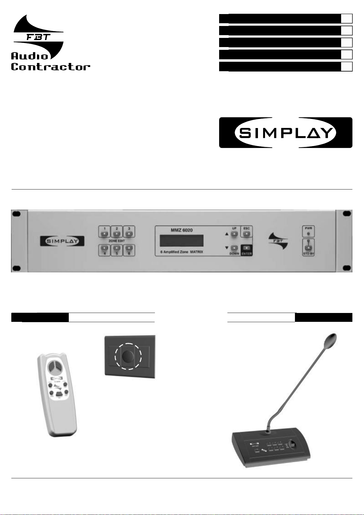
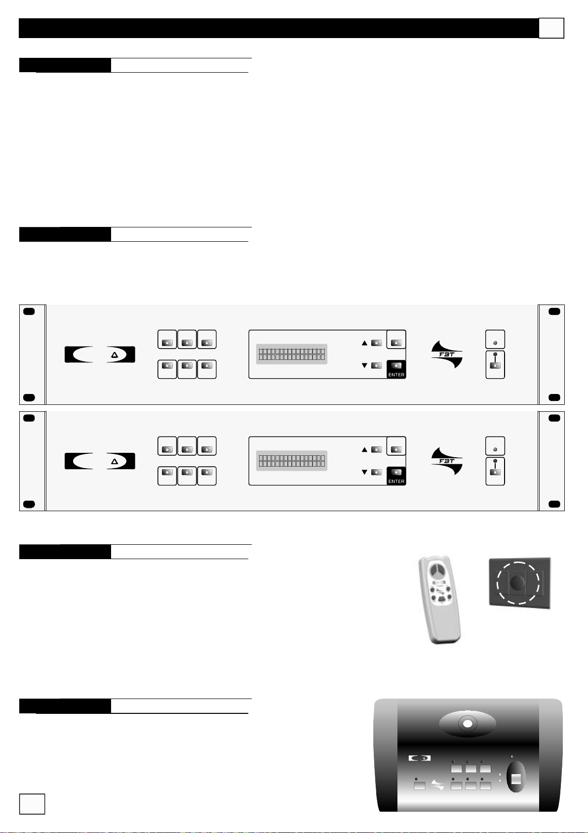
MMZ6020
Matrice6ingressisu6usciteperilcontrolloel’amplificazionedi6zoneaudio.
°4ingressistereoconlinkpercollegareunasecondamatrice(tape,tuner,CD,aux,)
°2connettoriRS-485percollegarealtrettantibasimicrofonichecon“paging”(mod.MBT6000)
°1ingressoXLR-F(AuxMic)accettauningressomicrofonicoounabasetipoMB-T6400S,BF-T5043Lepuòessere
prioritarioall’ingressoRS-485Mic;inoltre,suquestoingresso,èdisponibilelatensionePhantom24V
°6amplificatorida20WRMScadaunoconimpedenzadiuscita4Ohmmin.
°6connettoriRS-485(ZoneRemoteControl)percollegareicontrolliremotilocalichepermettonodiregolare,tramiteil
telecomandoadinfrarossi,ilvolume,itoniacutiebassi,l’accensione/spegnimentoescegliereilprogrammamusicale
(Tape,ecc.)
°1display2x16caratteripermettedivisualizzarelostatodelle6zoneaudio
MMZ6000
Matrice6ingressisu6usciteperilcontrolloel’amplificazionedi6zoneaudio.
°StessecaratteristichedellaMatriceMMZ6020senzaleuscitedipotenzanecessarieperpilotareglialtoparlanti
SIMPL Y
SIMPL Y
1 2 3
ZONEEDIT
4 5 6
1 2 3
ZONEEDIT
4 5 6
MMZ6020
6ZoneMATRIXAmplified
MMZ6000
6ZoneMATRIX
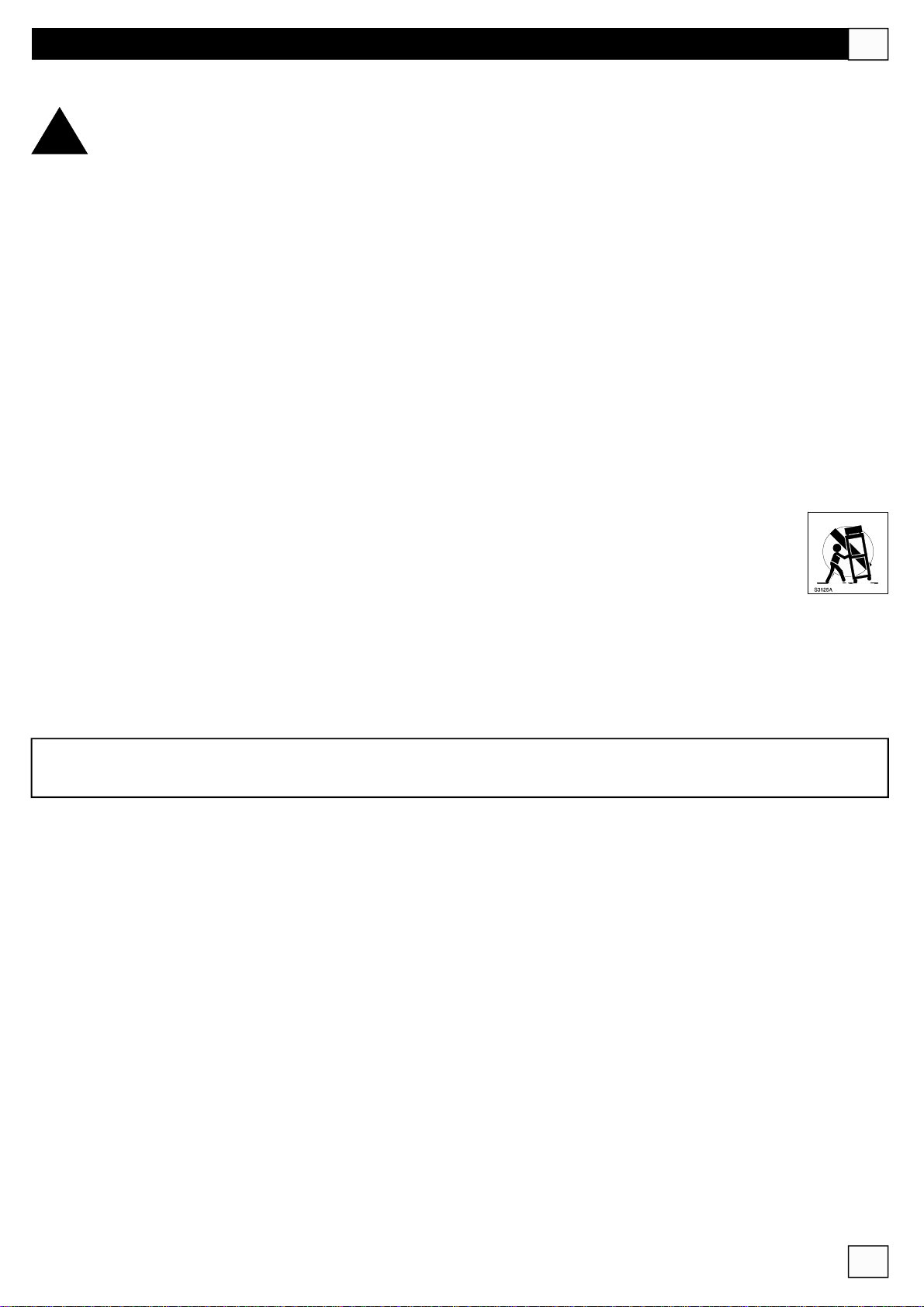
TRC6000
KitcompostodauntrasmettitoremodelloTX6000(telecomandoinfrarossi)eun
ricevitoreinfrarossimodelloRX6000
UP
DOWN
UP
DOWN
ESC
ESC
PWR
STDBY
PWR
STDBY
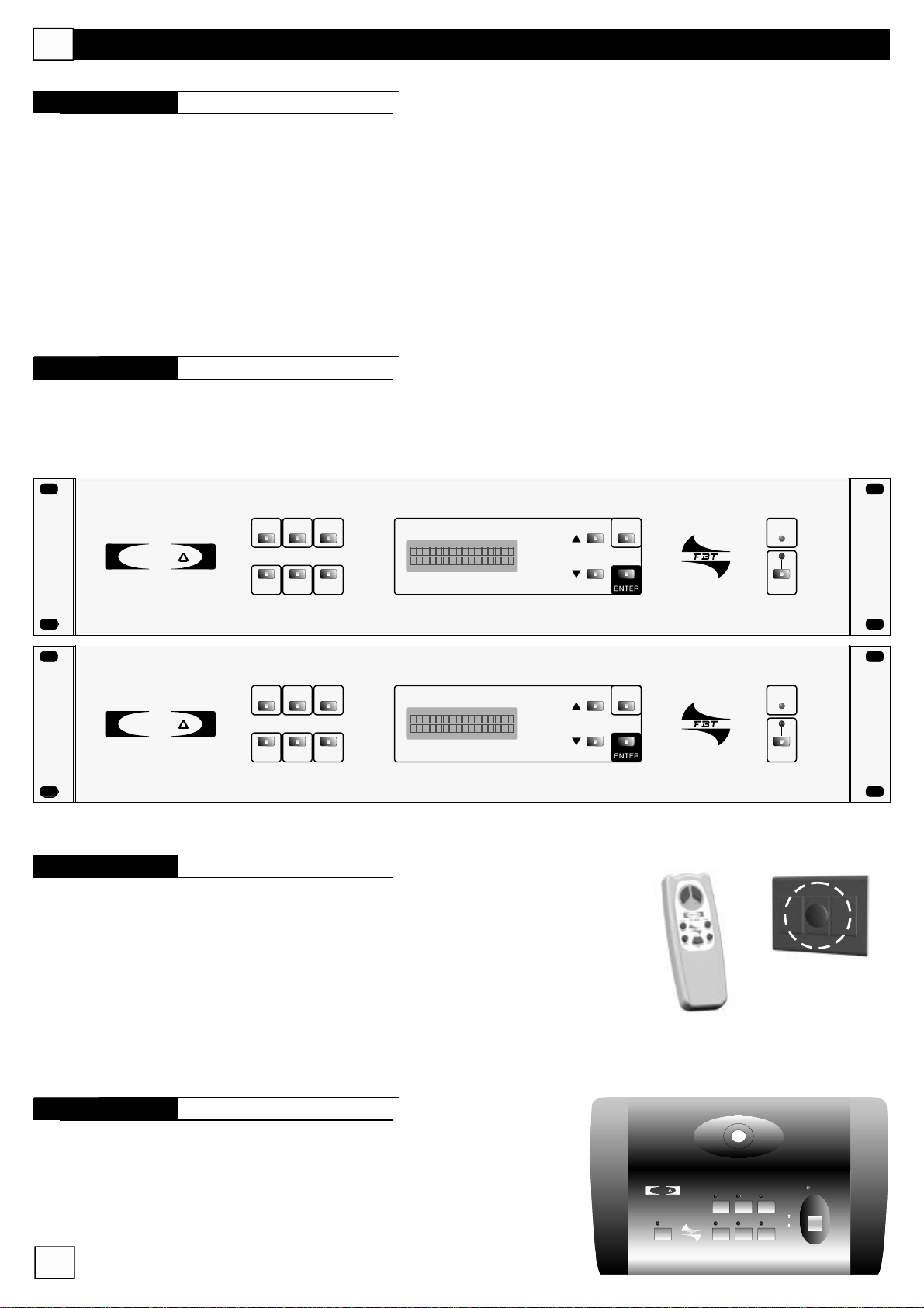
MBT6000
BasemicrofonicadisegnataperlematriciMMZ6020/6000collegabilecon
interfacciaRS-485
3
SIMPL Y
MBT6000
ALL
4 5 6
2
1
Gong
MIC
LOCK
OFF
3
MOM
Page 5
SIMPL Y
1 2 3
ZONEEDIT
4 5 6
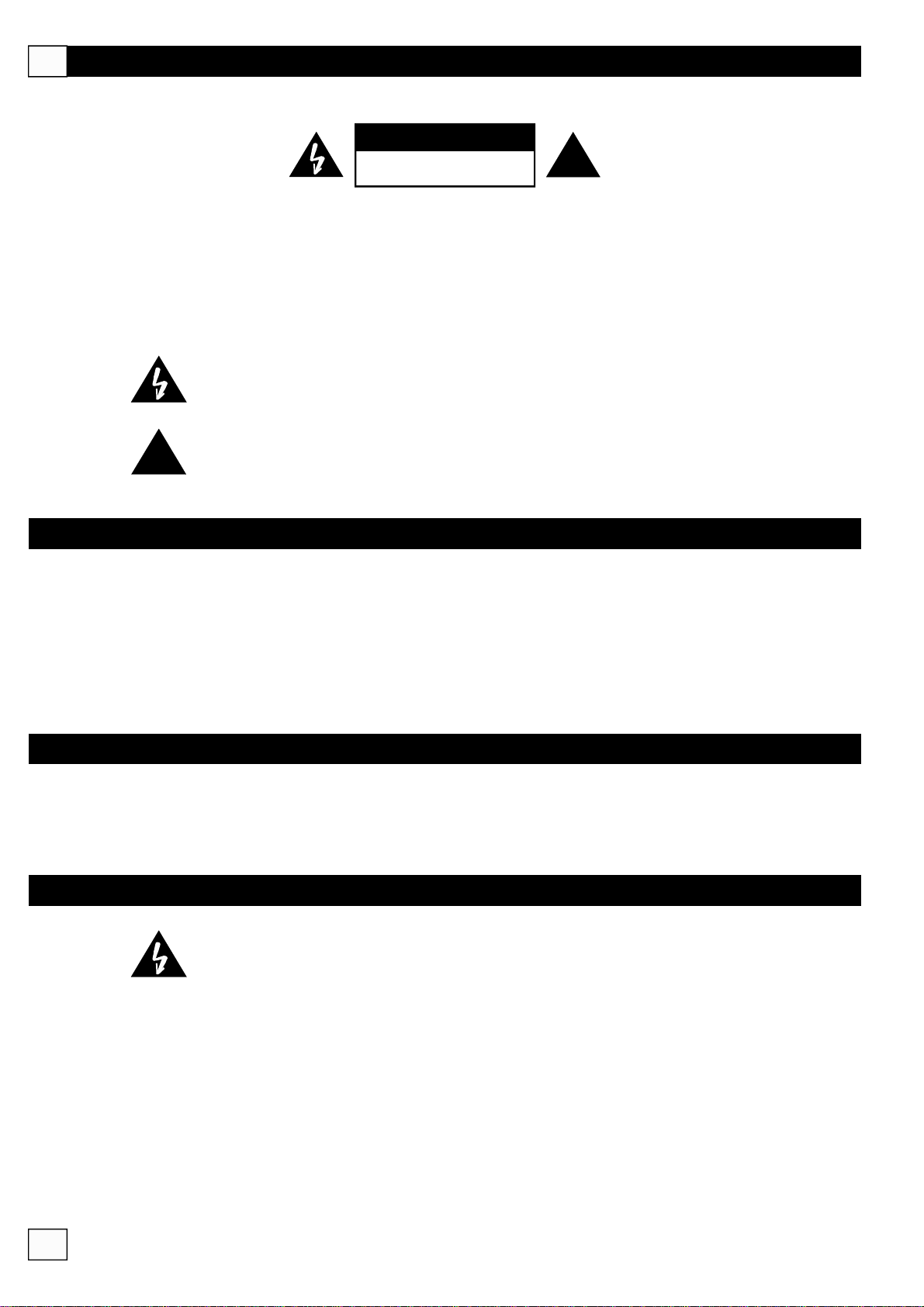
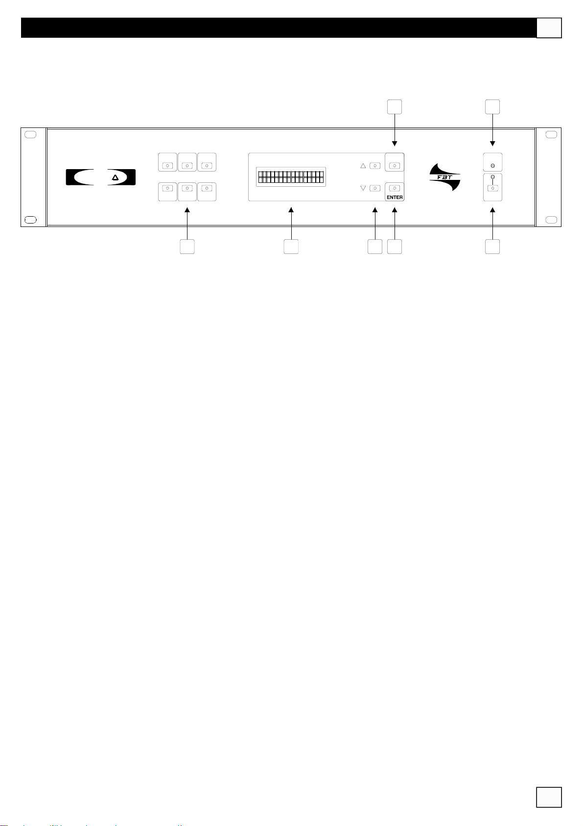
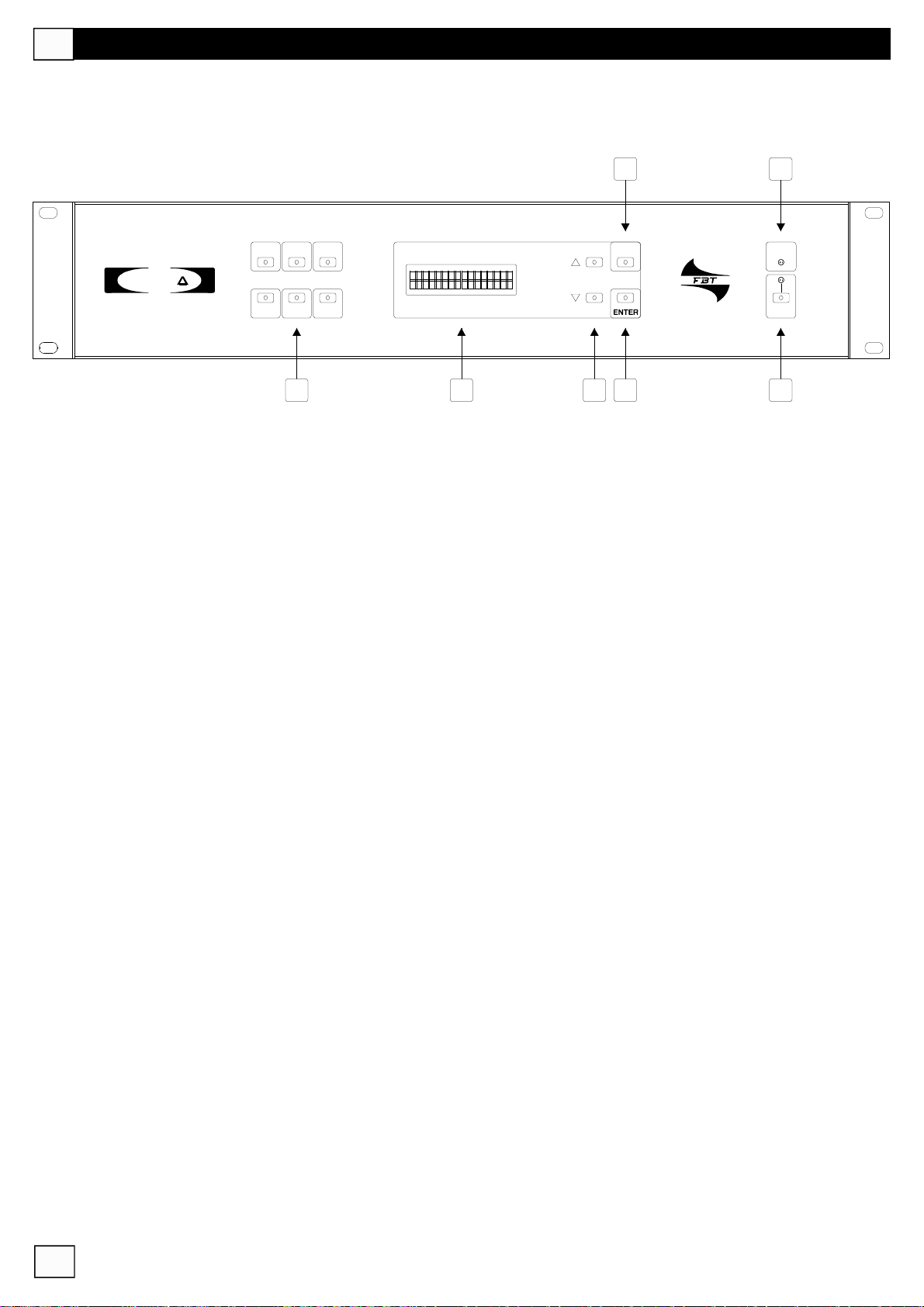
PANNELLOFRONTALE
MMZ6020
6AmplifiedZoneMATRIX
5 7
UP
ESC
DOWN
I
PWR
STDBY
1 2 3 4
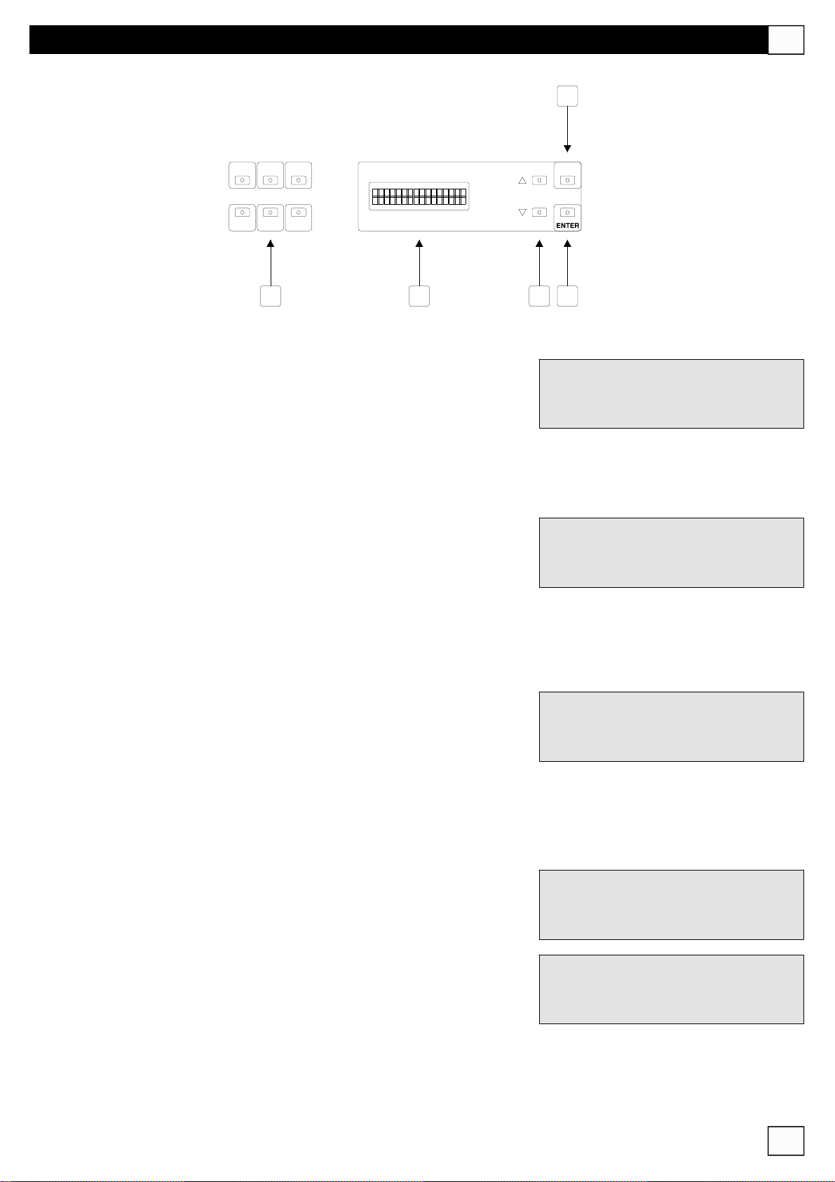
1
°
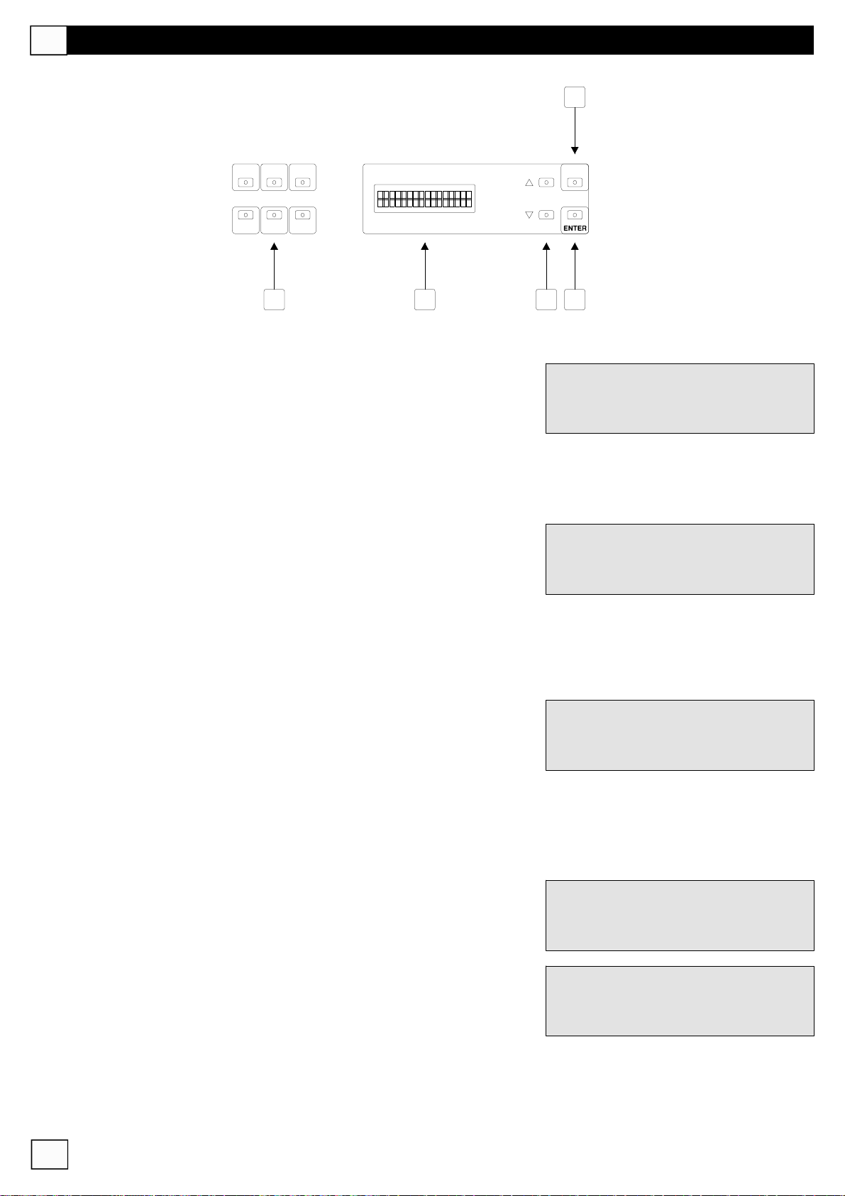
6tastiselettoridizona(1-2-3-4-5-6)
2
°
DisplayLCDretroilluminato16caratterix2linee
3
°
TastiUPeDOWNperincremento/decrementodelvaloredelparametroselezionato
4
°
TastoENTERperconfermareilvaloredelparametroselezionato
5
°
TastoESCcheannullal’operazioneimpostata
6
°
TastoSTAND-BY(solomodelloMMZ6020):disattivagliamplificatoriinterni
7
°
Ledchevisualizzal’accensionedell’apparecchioeffettuatatramitel’interruttorepostosulpannelloposteriore.
6
4
Page 6
I
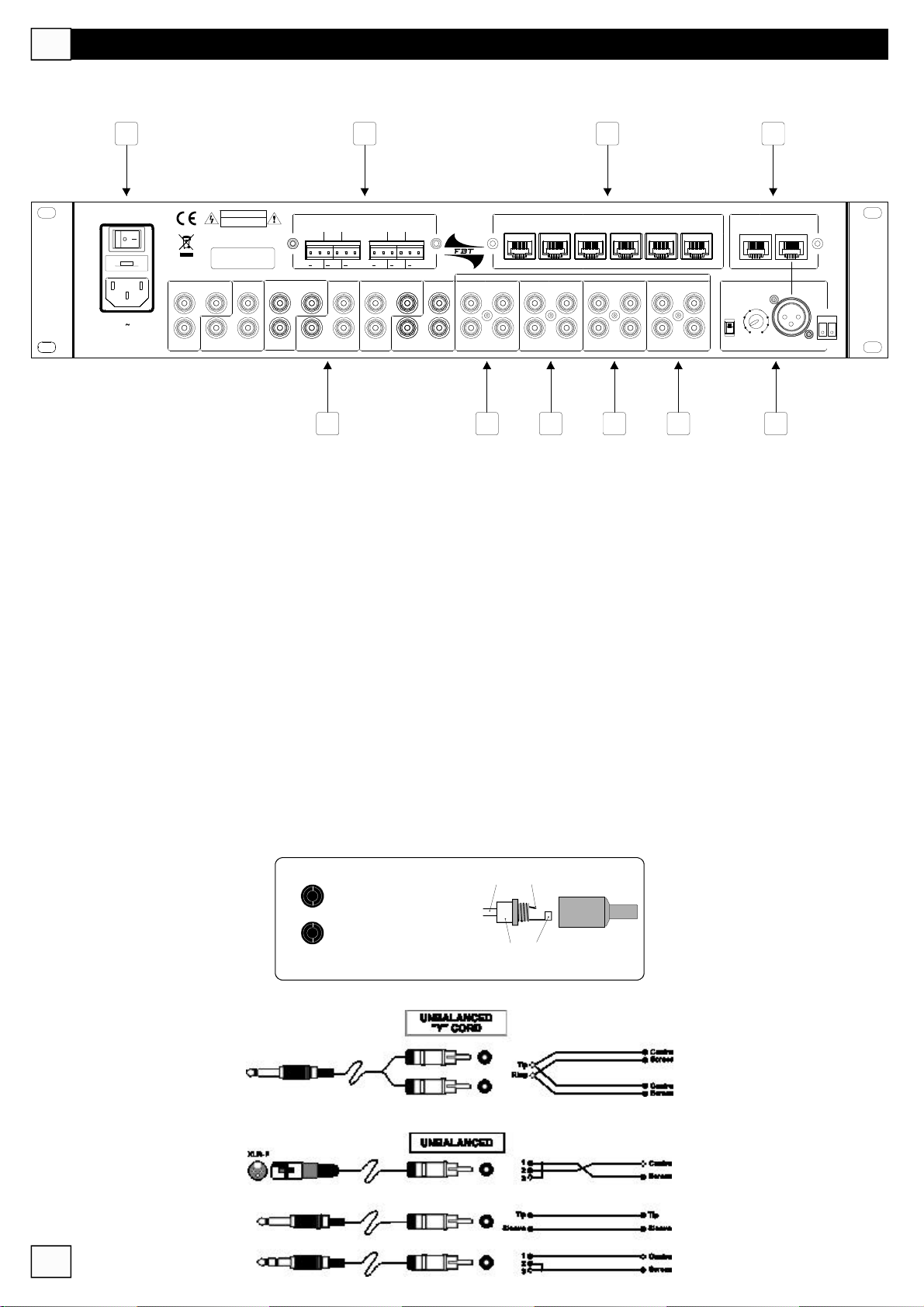
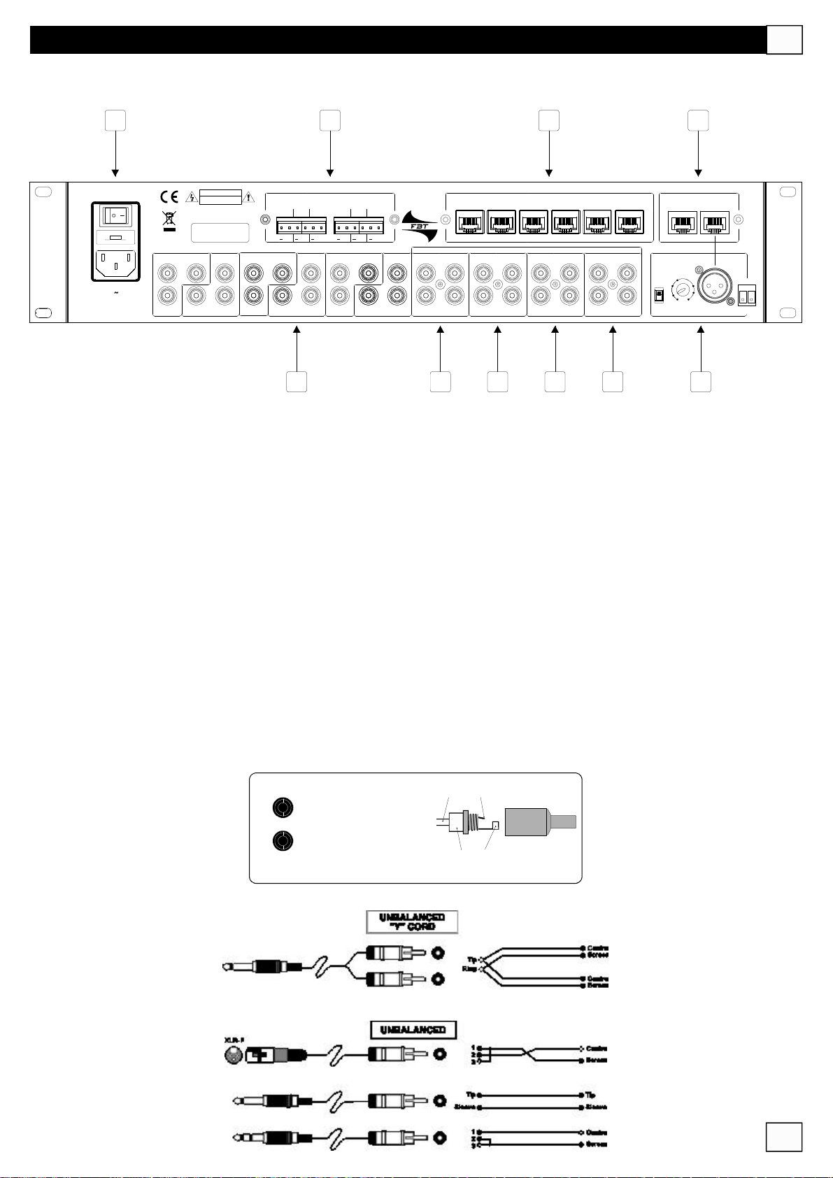
PANNELLOPOSTERIORE
8
CAUTION
RISKOFELECTRICSHOCK
DONOTOPEN
TOREDUCETHERISKOFELECTRICSHOCKDONOT
REMOVECOVER(ORBACK)NOUSERSERVICEABLE
PARTSINSIDEREFERSERVICINGTOQUALIFIED
SERVICEPERSONNEL
LEFT SUB/MNO
230Vac/T1.6A
PowerConsumption220VA
MadeinItaly
8
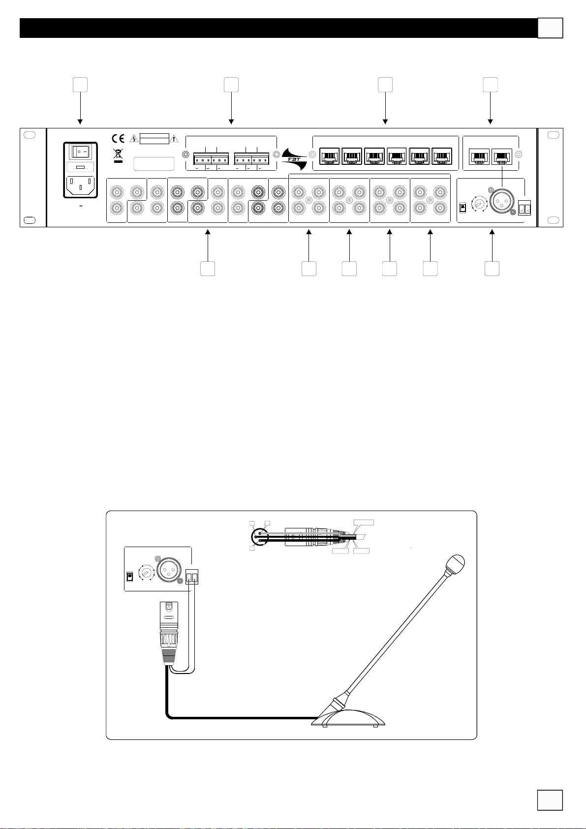
°IlcollegamentoallareteelettricaavvienetramiteunapresastandardIEC;primadicollegarel’apparecchioverificarechela
RIGHT
SUB/MNO
LEFT
RIGHT
LEFT SUB/MNO
SUB/MNO
RIGHT
10
SPKROUTPUTS4/8Ohm
6 5 4 3 2 1
LEFT
LEFT SUB/MNO
RIGHT
SUB/MNO
RIGHT
9
++++++
ZONE1ZONE2ZONE3ZONE4ZONE5ZONE6
MMZ6020
LEFT
RIGHT
15 16
ZONEREMOTECONTROL
LINK
INPUTS
LINK
L
R
IN
L
R
IN
AUX CD TUNER
L
R
LINK
IN
11 12 13 14
LINK
TAPE
MICREMOTECTRL
MIC1MIC2
123456
L
R
IN
7030 dB
PH
GAIN
24V PRIORITYAUXMIC1
17
tensionedialimentazionenonsiasuperioreaquellaindicata.Lapresacomprendeanchel’alloggiamentodelfusibiledi
protezionedelcircuitodialimentazione:incasodirotturadelfusibilequest’ultimovasostituitosolodafusibiliconuguali
caratteristicheelettriche.
Conl’interruttore(8)simetteinfunzionel’apparecchio;selamatricevieneinstallatainunportareck,assicurarsichelapresa
dialimentazionerisultifacilmenteaccessibile.
9
°Usciteaudioperlerelativezone(1-6):
SUB/MNO:uscitaperunsubwoofer;inmodalitàmonoriceveisegnalisommatiL/R
LEFT/RIGHT:uscitestereoperilcollegamentodiunamplificatoreaddizionaleoaltro.
N.B.Tuttigliingressi/usciteaudioconconnettoreditipoRCAsonopersegnalialivello“linea”(nonmicrofonici)
PreseaPinJack
Canalesinistro (Left)
L
R
Canaledestro (Right)
PinJackRCA
Fase+ Caldo(Hot)/Phase+
Massa Schermo(Ground)/Masse
5
Page 7
PANNELLOPOSTERIORE
I
8
CAUTION
230Vac/T1.6A
PowerConsumption220VA
MadeinItaly
RISKOFELECTRICSHOCK
DONOTOPEN
TOREDUCETHERISKOFELECTRICSHOCKDONOT
REMOVECOVER(ORBACK)NOUSERSERVICEABLE
PARTSINSIDEREFERSERVICINGTOQUALIFIED
SERVICEPERSONNEL
LEFT SUB/MNO
RIGHT
SUB/MNO
LEFT
RIGHT
RIGHT
SPKROUTPUTS4/8Ohm
6 5 4 3 2 1
LEFT SUB/MNO
SUB/MNO
9
0
1
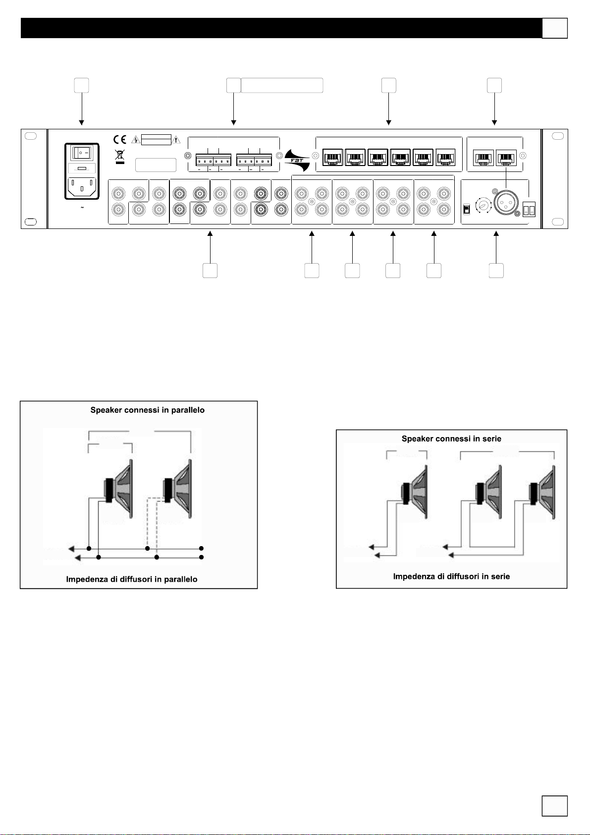
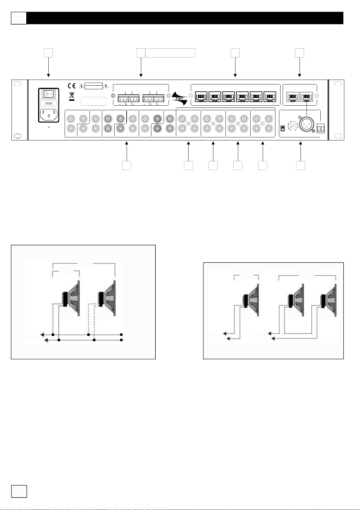
°6usciteperdiffusoriacustici(zone1-6).L’impedenzacomplessivaminimadiognilineadidiffusoriacusticinondeve
SOLOMODELLOMMZ6020
10
LEFT
LEFT SUB/MNO
RIGHT
SUB/MNO
RIGHT
++++++
ZONE1ZONE2ZONE3ZONE4ZONE5ZONE6
MMZ6020
LEFT
RIGHT
15 16
ZONEREMOTECONTROL
LINK
INPUTS
LINK
L
R
IN
L
R
IN
AUX CD TUNER
L
R
LINK
IN
11 12 13 14
LINK
TAPE
MICREMOTECTRL
MIC1MIC2
123456
L
R
IN
7030 dB
PH
GAIN
24V PRIORITYAUXMIC1
17
essereinferiorea4Ohm;lapotenzaerogabileperciascunauscitaèdi20W.
ATTENZIONE:Aprevenzionedieventualicortocircuiticoprireoisolareleterminazioniliberedeicaviodeiconnettori.
N.B.:Gliamplificatoriinternisonoattivisenonvengonocollegatiicomandiremoti(15).
4Ohm
8Ohm
8Ohm
SPKR
toamplifier
11 1312 14
°°°° Ingressiaudio(L_canalesinistro,R_canaledestro)percollegarel’uscitadiunasorgentemusicale(lettore
8Ohm
SPKR
toamplifier toamplifier
4Ohm
4Ohm
SPKR
4Ohm
SPKR
8Ohm
4Ohm
SPKR
CD,riproduttoredicassette,sintonizzatoreradio,ecc.).
6
Page 8
I
PANNELLOPOSTERIORE
8
CAUTION
RISKOFELECTRICSHOCK
DONOTOPEN
TOREDUCETHERISKOFELECTRICSHOCKDONOT
REMOVECOVER(ORBACK)NOUSERSERVICEABLE
PARTSINSIDEREFERSERVICINGTOQUALIFIED
SERVICEPERSONNEL
LEFT SUB/MNO
230Vac/T1.6A
PowerConsumption220VA
MadeinItaly
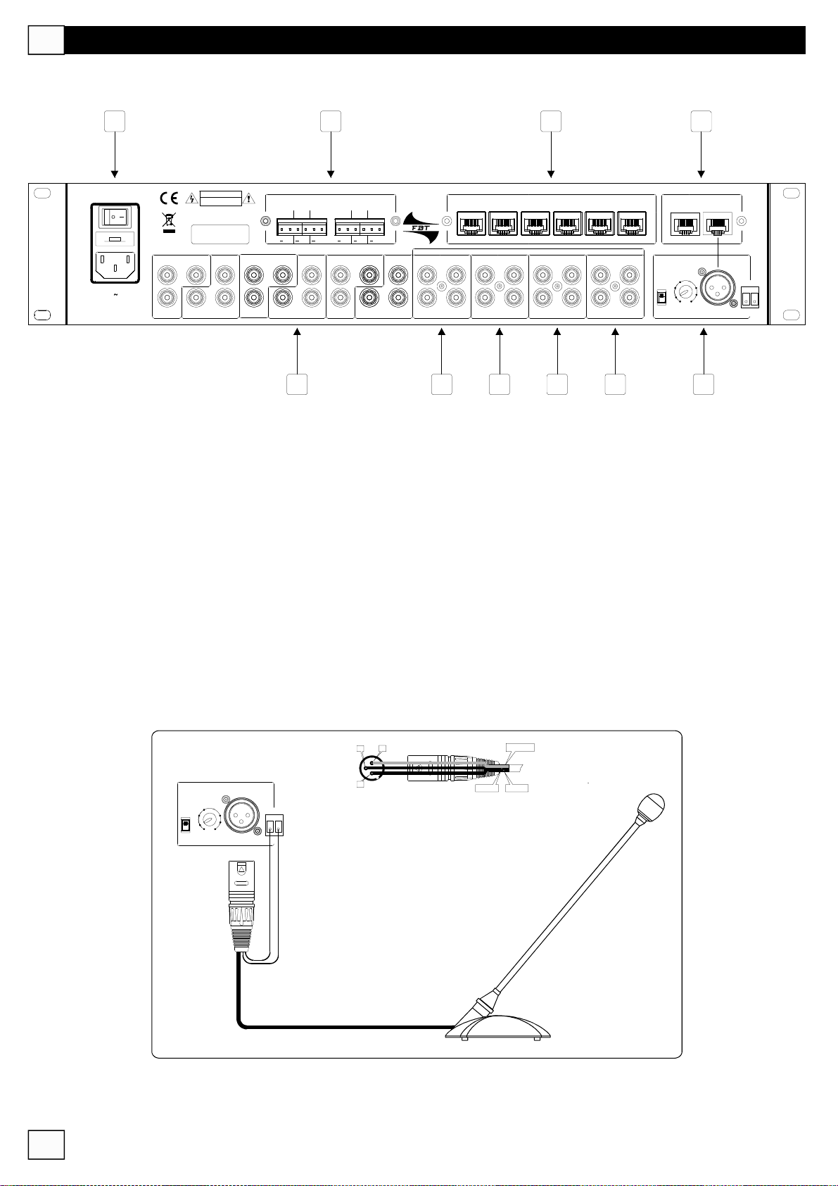
15
°6ingressitipoRS-485(unoperciascunazona)perilcollegamentodelcontrolloremotoRX6000(vedidescrizione
RIGHT
SUB/MNO
LEFT
RIGHT
LEFT SUB/MNO
SUB/MNO
RIGHT
10
SPKROUTPUTS4/8Ohm
6 5 4 3 2 1
LEFT
LEFT SUB/MNO
RIGHT
SUB/MNO
RIGHT
9
++++++
ZONE1ZONE2ZONE3ZONE4ZONE5ZONE6
MMZ6020
LEFT
RIGHT
15 16
ZONEREMOTECONTROL
LINK
INPUTS
LINK
L
R
IN
L
R
IN
AUX CD TUNER
L
R
LINK
IN
11 12 13 14
LINK
TAPE
MICREMOTECTRL
MIC1MIC2
123456
L
R
IN
7030 dB
PH
GAIN
24V PRIORITYAUXMIC1
17
pag.12)
16
°2connettoriRS-485percollegarelebasimicrofonichededicatemodelloMBT6000con“paging”(vedidescrizionepag.11)
17
°IngressoXLR-F(AUXMIC1)perilcollegamentodiunmicrofonoodiunabasemicrofonicachepuòessereprioritario
all’ingressoMIC1(16);èpredispostoperlatensionePhantom24V,conlaregolazionedelGaineilcontattodi“priority”.
COLD
-
GROUND
HOT+
13
2
7030 dB
PH
GAIN
24V
PRIORITYAUXMIC1
7
EsempiodicollegamentodellabasemicrofonicaBF-T5043Lconpriorità
Page 9
1 2 3
ZONEEDIT
MENÙDIUTILIZZO
MMZ6020
I
5
UP
ESC
4 5 6
1
6AmplifiedZoneMATRIX
2 3 4
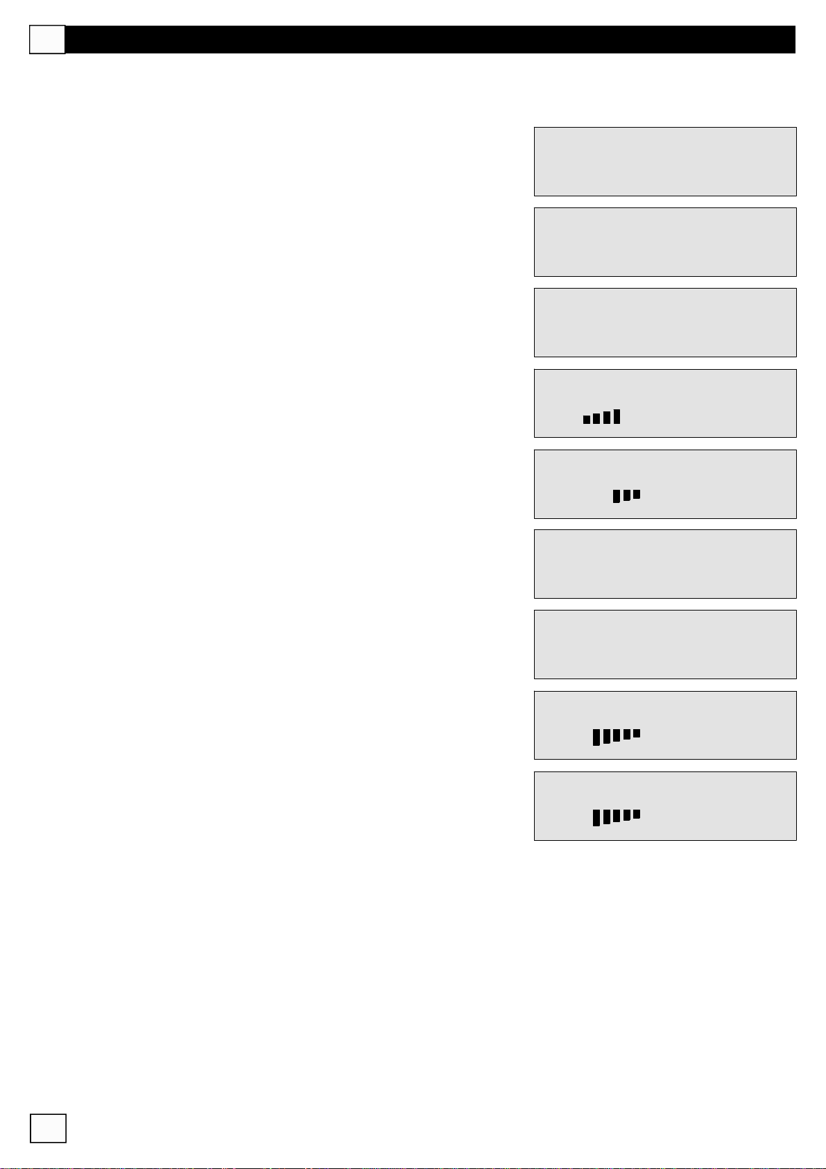
Nelmenùdiutilizzovengonoriportatituttiiparametrinecessari
perilfunzionamentodell’apparecchio(controllovolumi,controllo
toni,selezionemusica,ecc.).
Nellaschermataprincipalesonoelencatele6zone(1,2,3,4,5,6)
DOWN
MatrixMMZ6020
V1.0byFBT
SelectZone
123456
PeraccedereallaZona1premereiltastorelativo(1).
Ilprimoparametrocheappareèquellocheriguardailtipodi
sorgentemusicaledaattivare.PremereENTER(4).
ConitastidiscorrimentoUPeDOWN(3)selezionareiltipodi
sorgentedesiderata(inquestoesempio“Tape”).PremereENTER
perconfermare.
AllasecondapressionedeltastoENTERsientraneimenùdelle
funzionicheriguardanolasorgentedellazonapresceltaedei
parametridaimpostare(Loudness,Mute,Treble,Bass,Mode
S/M,Priority,OutVol,MonoVol,Sub/Full).
Zone1Function
SelectSource
Zone1Source
Tape
Zone1Function
SelectLoudness
8
Page 10
I
MENÙDIUTILIZZO
OgnifunzionevaselezionatatramiteiltastoENTERperpoi
modificarneiparametriscorrendoconitastiUPeDOWN:
LOUDNESS: esaltaisuonipiùgraviequellipiùacuti,necessario
acompensarelascarsasensibilitàdell’orecchioumanoverso
l’estremitàdellospettroudibile(gammadifrequenza).
MUTE:annullailsegnalesututteleuscite
TREBLE: regolalatimbricadelsuonodellealtefrequenze;la
regolazionevada-14dBa+14dB
BASS: regolalatimbricadelsuonodellebassefrequenze;la
regolazionevada-15dBa+15dB
Zone1Function
SelectLoudness
Zone1Loudness
No
Zone1Mute
No
Zone1Treble
+8dB
Zone1Bass
-8dB
MODES/M:impostalamodalitàdiascoltoStereooMono
PRIORITY: nelcasodiutilizzodelmicrofonoausiliario(17)
impostalaprioritànellazonaselezionata.
OUTVOL.: regolaillivellodivolumeda-1dBa-50dB;quandoil
volumeèpostoalminimovalorecomparelascritta“mute”.
MONOVOL: regolaillivellodivolumeda-1dBa-50dBin
configurazione“mono”;quandoilvolumeèpostoalminimovalore
comparelascritta“mute”.
Zone1ModeS/M
Mono
Zone1Priority
Yes
Zone1OutVol
-21dB
Zone1MonoVol
-21dB
9
Page 11
MENÙDIUTILIZZO
I
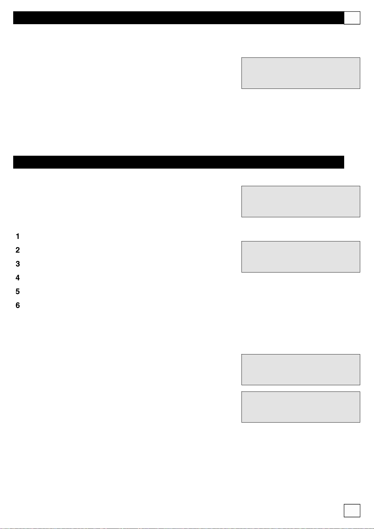
SUB/FULL: èpossibileimpostareunfiltro“passa-basso”
all’uscitaSUB/MNO;l’attivazionedelfiltroconsentel’utilizzodiun
subwooferattivo(dedicatoperlesolebassefrequenze).
IMPOSTAZIONEDELLASENSIBILITÀEDELGAIN
Nelmenù“SelectZone”puòessereregolatalaSensibilitàeilGain
dituttigliingressi.
TramiteiltastoESCentrarenelmenù“SelectSource”escegliere,
tramiteipulsantidiZONEEDIT(1)lasorgentesonoraincui
regolareiparametridiGaineSensibilità:
°M1(microfono1MBT6000)
Zone1Function
SelectSub/Full
SelectZone
123456
°TP(tape)
°M2(microfono2MBT6000)
°CD(lettoreCD)
°A(ausiliario)
°TU(sintonizzatore)
IlparametrodiSensibilitàdefiniscel’ampiezzadelsegnaleche
deveesserefornitainingressoall’amplificatoreperottenerein
uscitalapotenzamassima.Laregolazionevada0a15dB.
IlcontrollodelGainmisuradiquantouncircuitoelettronico
amplificaunsegnale.Laregolazionevada-80dBa+32dB.
SelectSource
M1TPM2CDATU
TunerFunction
SelectSensit.
TunerFunction
SelectGain
10
Page 12
I
CONTROLLIREMOTI
MBT6000
1 2 3 4
IN
NETWORK
SIMPL Y
ON
CHIME
SETUP
L R
AUXILIARY
VOL. MAST.
MADEINITALYMBT6000
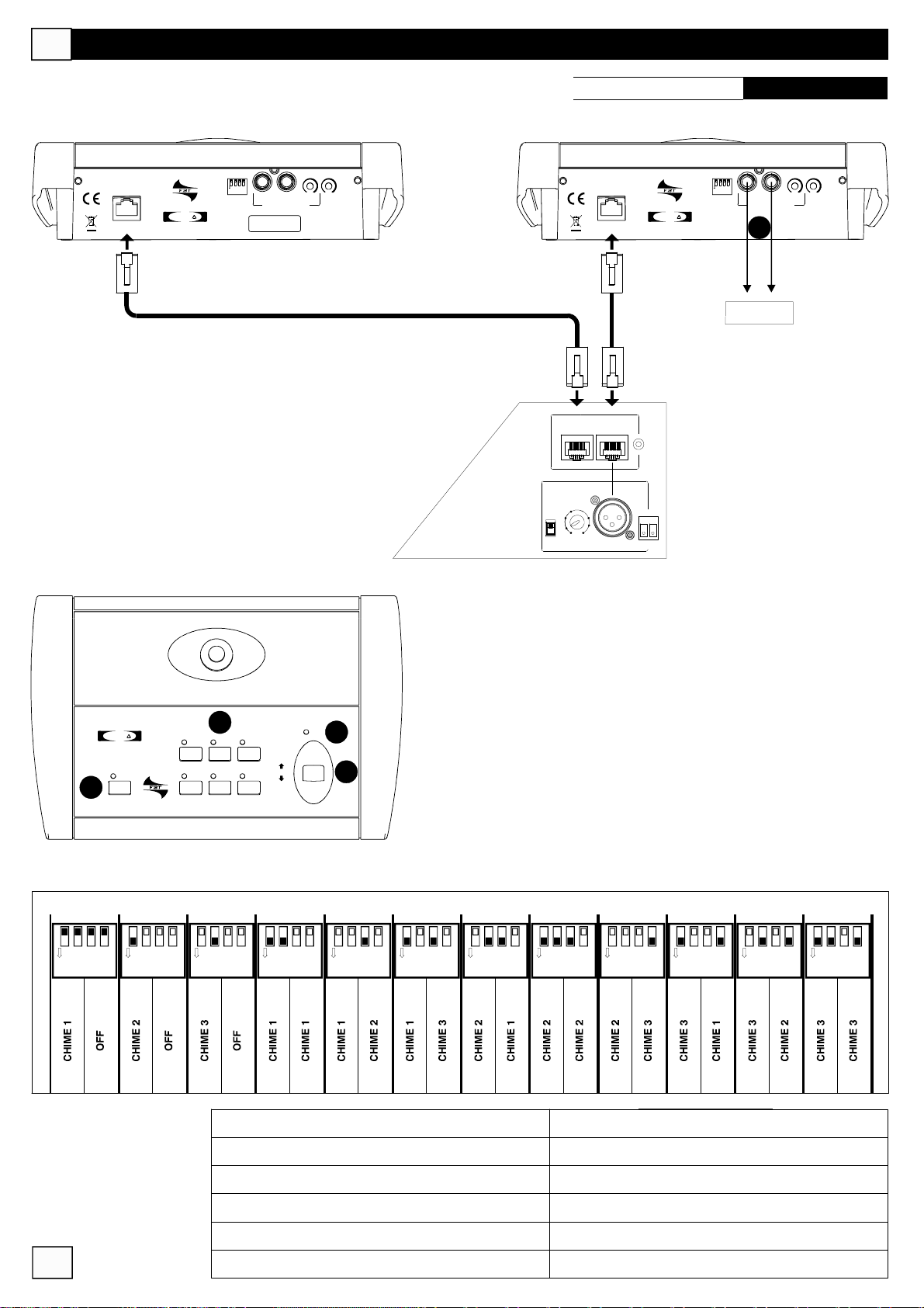
LabasemicrofonicaMBT6000vieneutilizzatacomecomando
remotoperselezionezoneeannuncidestinataesclusivamente
adunutilizzoconlematriciFBTAudioContractormodelloMMZ
6020/MMZ6000dacuiprelevadirettamenteanche
l’alimentazione.
1)
Interruttoreatreposizioni;nellaposizionecentrale(OFF)labase
microfonicaèdisattivata;nellaposizioneLOCKl’interruttoreè
stabile;nellaposizioneMOMlabaseèattivafinoalmomentodel
rilascio.
2)
Illedaccesosegnalalapresenzadelsegnalemicrofonicoinuscita.
3)
LafunzioneALLpermetteladiffusionediunannunciointuttele
zoneaudiodelsistema,interrompendol’eventualemusicadi
sottofondo;
relativoled.
4)
Tastiperlaselezionedellazonaincuidovràesserediffuso
l’annunciomicrofonico;l’attivazionedellazonaèvisualizzata
dall’accensionedelrelativoled.
5)
PreseCINCHRCAperilcollegamentodiunasorgenteausiliaria
4
SIMPL Y
MBT6000
ALL
3
5
4
1 2 3
MIC
6
LOCK
OFF
MOM
2
1
(es.lettoreCD);inquestocasolabasemicrofonicapuòessereusata
comepostazionelocaleinunasingolazona.
1 2 3 4
IN
MICREMOTECTRL
7030 dB
PH
GAIN
24V
NETWORK
MIC1MIC2
PRIORITYAUXMIC1
SIMPL Y
ON
CHIME
SETUP
CDPLAYER
L R
AUXILIARY
5
VOL. MAST.
MADEINITALYMBT6000
l’attivazionedellazonaèvisualizzatadall’accensionedel
Tabelladiconfigurazionedeitonidipreavviso(DINDON)
1 2 3 4ON1 2 3 4ON1 2 3 4ON1 2 3 4ON1 2 3 4ON1 2 3 4ON1 2 3 4ON1 2 3 4ON1 2 3 4ON1 2 3 4ON1 2 3 4ON1 2 3 4
ON
INIZIO FINE INIZIO FINE INIZIO FINE INIZIO FINE INIZIO FINE INIZIO FINE INIZIO FINE INIZIO FINE INIZIO FINE INIZIO FINE INIZIO FINE INIZIO FINE
11
CODE:31929
Caratteristiche
Direttività
Rispostainfrequenza
Sensibilità
Impedenzadiuscita
Materiale
microfonodinamico
cardioide
100Hz÷12kHz
-75dB±3dB
500Ohm
ABSconfondoinacciaio
Page 13
CONTROLLIREMOTI
CODE:31144
TRC6000
KitcompostodauntrasmettitoremodelloTX6000(telecomandoinfrarossi)eun
ricevitoreinfrarossimodelloRX6000.
Iltrasmettitoredizonapermettediregolareilvolume,itoniacutiebassi,
#
accendere/spegnerel’audio,scegliereiltipodiingresso(tape,tuner,ecc).
Ilricevitoreècollegatoallamatriceconuncavettotelefonicoa4conduttori
#
(massimalunghezza500mt.)cheterminaconunconnettoreRJ-45(pin
1,2,3,4).
IMPORTANTE:
Ladistanzamassimadifunzionamentotrailricevitore/trasmettitoreèdi20mt
(senzaostacolitraloro).
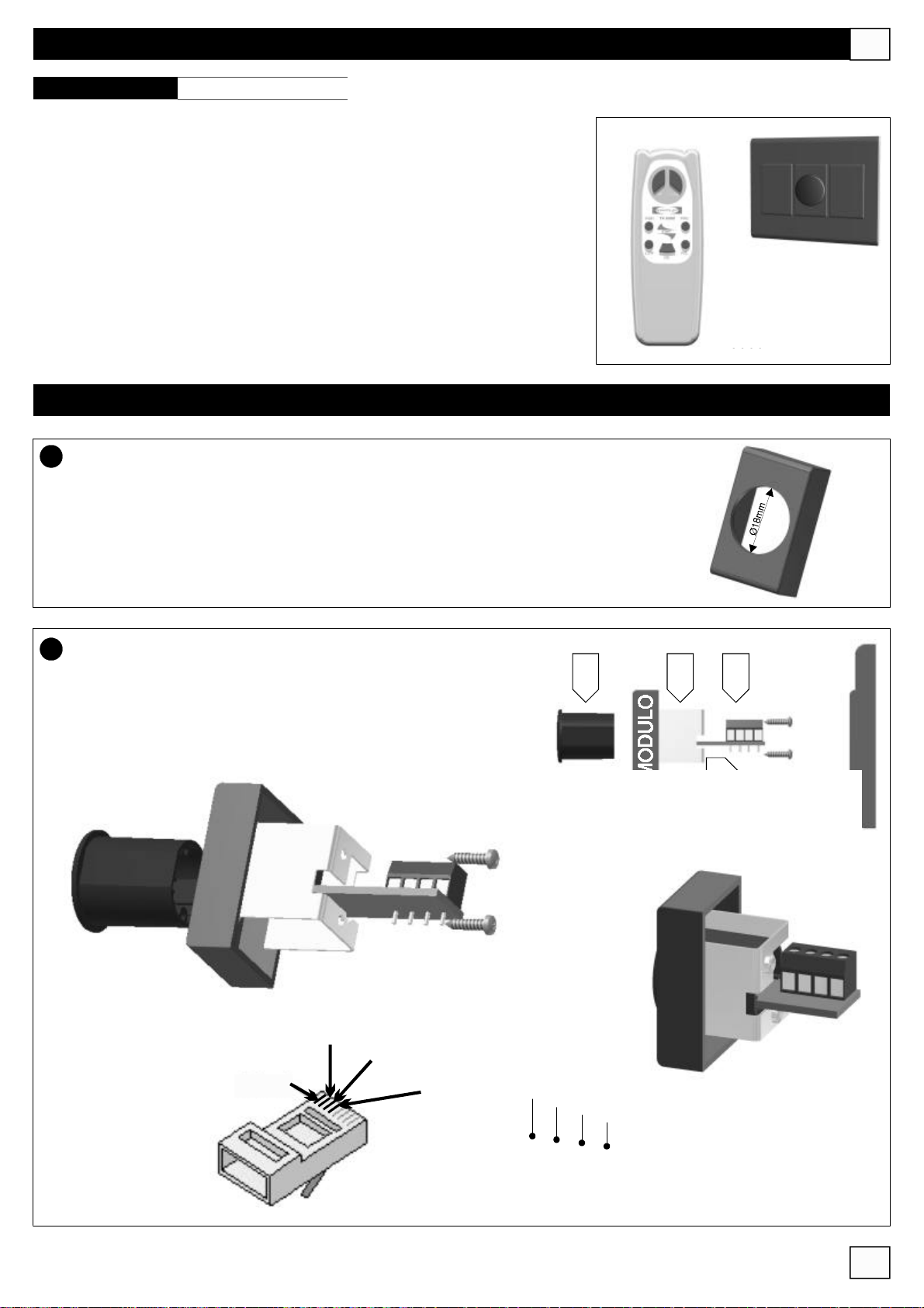
INSTALLAZIONE
1
Utilizzarecomesupporto1modulopercomuniscatole“portafrutti”usatenegli
impiantielettriciepraticareunforo(Ø18mm)alcentroutilizzandountrapano.
I
RX6000
TX6000
Inserirenelseguenteordine:
2
1)laguarnizionecilindrica(A)nelmodulo
2)ilcircuitostampato(B)nellaguarnizionecilindrica
3)ilfermoinalluminio(C),fissandolotramiteleappositevitinei
fori(D)
D
Pin2
Pin3
Pin1
Pin4
Pin1
A BC
Pin2
Pin3
Pin4
RJ45
12
Page 14
I
Livellomax.ingressi
Tape,Tuner,CD,Aux
GuadagnomaxingressoAuxMic1 -70dB
Tensionephantom 24V
Toniacuti ±14dB@12kHz
Tonibassi ±15dB@12kHz
LivellousciteLeft,Right,Sub/Mono +3dB
Rispostainfrequenza(@-3dB) 30Hz÷50kHz
THD-N(@usciteL,R,Sub/Mono) 0,013%
Potenzauscitaspeaker(@1%THD+N20Hz÷20kHz) 6x20WRMS
Rapportosegnale/rumore 88dBtipico
AlimentazioneMute -90dBmin.
ProtezionesulleusciteSPKR Cortocircuito/Termica
Alimentazione 230Vac50/60Hz
Assorbimento 220VA
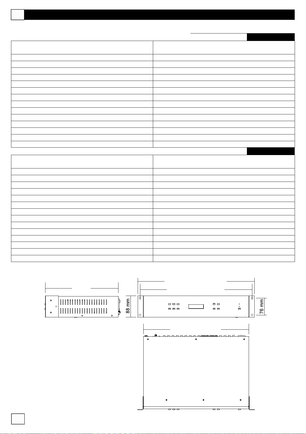
Dimensioni 2unitàrack
Livellomax.ingressi
Tape,Tuner,CD,Aux
GuadagnomaxingressoAuxMic1 -70dB
Tensionephantom 24V
Toniacuti ±14dB@12kHz
Tonibassi ±15dB@12kHz
LivellousciteLeft,Right,Sub/Mono +3dB
Rispostainfrequenza(@-3dB) 30Hz÷50kHz
THD-N(@usciteL,R,Sub/Mono) 0,013%
Potenzauscitaspeaker(@1%THD+N20Hz÷20kHz) ----------
Rapportosegnale/rumore ---------AlimentazioneMute ---------ProtezionesulleusciteSPKR ---------Alimentazione 230Vac50/60Hz
Assorbimento 30VA
Dimensioni 2unitàrack
SPECIFICHETECNICHE
Gainmin.+10dBu(245V)
max.-5dBu(435V)
Gainmin.+10dBu(245V)
max.-5dBu(435V)
MMZ6020
MMZ6000
13
305mm
482mm
465mm
438mm
Page 15
!
ATTENTION
WARNING
RISKOFELECTRICSHOCK
DONOTOPEN
TOREDUCETHERISKOFELECTRICSHOCK
DONOTREMOVECOVER(ORBACK)
REFERSERVICINGTOQUALIFIEDSERVICEPERSONNEL
TOREDUCETHERISKOFFIREORELECTRICSHOCK
DONOTEXPOSETHISEQUIPMENTTORAINORMOISTURE
WHEREMARKED,THISSYMBOLINDICATESADANGEROUSNON-ISOLATED
VOLTAGEINSIDETHELOUDSPEAKER:SUCHVOLTAGECOULDBE
SUFFICIENTTORESULTINTHERISKOFELECTRICSHOCK
WHEREMARKED,THISSYMBOLINDICATESIMPORTANTUSAGE
ANDMAINTENANCEINSTRUCTIONSINTHEENCLOSED
DOCUMENTS.PLEASEREFERTOTHEMANUAL
NOUSERSERVICEABLEPARTSINSIDE
!
UK
PRECAUTIONS
°Forproperairventilationpleasemakesuretoleavesufficientclearance(min.11inch.)onallsidesofthedevice.
°Pleasedonotcovertheventilationslotswithpapers,tablecloths,curtains,etc.inordernottopreventventilationofthe
device
°Pleasedonotplaceanynakedflamesource,suchaslightedcandles,onthedevice.
°Pleasekeepthedeviceawayfromwaterspringsandsplashesandpleasedonotplaceanyobjectscontainingliquids,such
asvases,onthedevice.
INSTALLATION
°Whentheunitisinstalledinarackenclosure,therackmusthavealltheprerequisitesrequiredbytheEN60439-1standard,
inparticulartherearpartmustbeclosedbymeansofsuitablepanels.
CONNECTIONS
°Beforeusingtheamplifiermakesurethattheappliance’svoltageisinaccordancetoyourmainssupply.Connectthe
amplifieronlytogroundedmainsoutlets.
°Toavoidtheriskofelectricalshocknevertouchthebareconductorsleadingtotheoutputterminalsoftheamplifierwhenitis
inoperation.
°Theunitmustonlybesuppliedfromthemainsafterallconnectionshavebeencompleted.
°TOCONNECTLOUDSPEAKERSUSEBOOT’SCABLESEXCLUSIVELY
14
Page 16
UK
IMPORTANTSAFETYINSTRUCTIONS
!
1)Readtheseinstructions
2)Keeptheseinstructions
3)Heedallwarnings
4)Followallinstructions
5)Donotusethisapparatusnearwater
6)Cleanonlywithdrycloth
7)Donotblockanyventilationopenings.Installinaccordancewiththemanufacturer’sinstructions.
8)Donotinstallnearanyheatsources,suchasradiators,heatregisters,stovesorotherapparatus(includingamplifiers)that
produceheat
9)Donotdefeatthesafetypurposeofthepolarizedorgrounding-typeplug.Apolarizedplughastwobladeswithonewider
thantheother.Agroundingtypeplughastwobladesandathirdgroundingprong.Thewidebladeorthethirdprongare
providedforyoursafety.Iftheprovidedplugdoesnotfitintoyouroutlet,consultanelectricianforreplacementoftheobsolete
outlet.
10)Protectthepowercordfrombeingwalkedonorpinchedparticularlyatplugs,conveniencereceptacles,andthepoint
wheretheyexitfromtheapparatus.
11)Onlyuseattachments/accessoriesspecifiedbythemanufacturer.
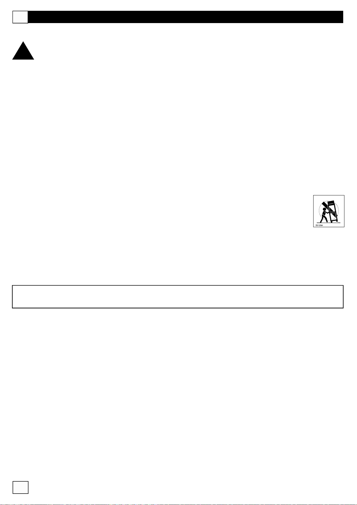
12)Useonlywiththecart,stand,tripod,bracket,ortablespecifiedbythemanufacturerorsoldwiththe
apparatus.Whenacartisused,usecautionwhenmovingthecart/apparatuscombinationtoavoidinjuryfromtipover.
13)Unplugthisapparatusduringlightningstormsorwhenunusedforlongperiodsoftime.
14)Referallservicingtoqualifiedservicepersonnel.Servicingisrequiredwhentheapparatushasbeen
damagedinanyway,suchaspower-supplycordorplugisdamaged,liquidhasbeenspilledorobjectshave
fallenintotheapparatus,theapparatushasbeenexposedtorainormoisture,doesnotoperatenormally,orhasbeen
dropped.
THEDEVICEMUSTBECONSTANTLYCONNECTEDTOTHEMAINSTHROUGHAPERFECTLYFUNCTIONINGGROUNDING
CONDUCTOR.
Thisdevicefeaturesapoweroutlet;installthedevicesothatthesocketforthepowercordcanbeaccessedeasily.
15
Page 17
MAINFEATURES
UK
MMZ6020
6-inx6-outmatrixforthecontrolandamplificationof6audiozones.
°4stereoinputswithlinktoconnectanothermatrix(Tape,Tuner,CD,Aux)
°2RS-485connectorsfortheconnectionoftwopagingmicrophoneconsole(mod.MBT6000)
°1XLR-F(AuxMic)inputallowstoconnectamicrophoneinputoraMB-T6400S,BF-T5043Lconsoleandcanhave
priorityovertheRS-485Micinput;moreover,24VPhantompowerisavailableonthisinput
°620WRMSamplifiers,eachwith4ohmminimumoutputimpedance
°6RS-485connectors(ZoneRemoteControl)fortheconnectionoflocalremotecontrolsthat,allow toadjust,troughthe
IRremotecontrol:volume,highandlowtones,poweron/offandmusicprogrammeselection(Tape,etc.)
°12x16characterdisplayallowingtoviewthestatusofthe6audiozones
MMZ6000
6-inx6-outmatrixforthecontrolandamplificationof6audiozones.
°SamefeaturesastheMMZ6020matrix,withoutthepoweroutputsneededtodrivetheloudspeakers
SIMPL Y
SIMPL Y
1 2 3
ZONEEDIT
4 5 6
1 2 3
ZONEEDIT
4 5 6
MMZ6020
6ZoneMATRIXAmplified
MMZ6000
6ZoneMATRIX
DOWN
DOWN
TRC6000
KitincludingaTX6000transmitter(IRremotecontrol)andaRX6000IRreceiver
UP
ESC
UP
ESC
PWR
STDBY
PWR
STDBY
MBT6000
MicrophoneconsoledesignedfortheMMZ6020/6000matrixes,thatcanbe
connectedtoRS-485interface.
16
SIMPL Y
MBT6000
ALL
4 5 6
2
1
Gong
MIC
LOCK
OFF
3
MOM
Page 18
UK
SIMPL Y
1 2 3
ZONEEDIT
4 5 6
FRONTPANEL
MMZ6020
6AmplifiedZoneMATRIX
5 7
UP
ESC
DOWN
PWR
STDBY
1 2 3 4
1
°
6zoneselectionswitches(1-2-3-4-5-6)
2
°
16x2backlitLCDdisplay
3
°
UPandDOWNbuttonstoincrease/decreasetheselectedparametervalue
4
°
ENTERbuttontoconfirmthevalueoftheselectedparameter
5
°
ESCbuttontocanceltheoperationset
6
°
STAND-BYbutton(MMZ6020only)forinternalamplifiersswitchingoff
7
°
Leddisplayingthattheequipmentisswitchedonbytherearpanelswitch
6
17
Page 19
REARPANEL
UK
8
CAUTION
RISKOFELECTRICSHOCK
DONOTOPEN
TOREDUCETHERISKOFELECTRICSHOCKDONOT
REMOVECOVER(ORBACK)NOUSERSERVICEABLE
PARTSINSIDEREFERSERVICINGTOQUALIFIED
SERVICEPERSONNEL
LEFT SUB/MNO
230Vac/T1.6A
PowerConsumption220VA
MadeinItaly
8
°
ConnectionwiththemainsisbymeansofastandardIECsocket;beforeconnectingthedevice,makesurethatthe
RIGHT
SUB/MNO
LEFT
RIGHT
LEFT SUB/MNO
SUB/MNO
RIGHT
10
SPKROUTPUTS4/8Ohm
6 5 4 3 2 1
LEFT
LEFT SUB/MNO
RIGHT
SUB/MNO
RIGHT
9
++++++
ZONE1ZONE2ZONE3ZONE4ZONE5ZONE6
MMZ6020
LEFT
RIGHT
15 16
ZONEREMOTECONTROL
LINK
INPUTS
LINK
L
R
IN
L
R
IN
AUX CD TUNER
L
R
LINK
IN
11 12 13 14
LINK
TAPE
MICREMOTECTRL
MIC1MIC2
123456
L
R
IN
7030 dB
PH
GAIN
24V PRIORITYAUXMIC1
17
supplyvoltageisnothigherthantheindicatedvoltage.Thesocketalsoincludesthehousingofpowercircuit
protectionfuse:ifthefusebreaks,itshallonlybereplacedbyfuseswithequalelectricalfeatures.
Thepowerswitch(8)turnsthedeviceon;ifthematrixismountedinarackcabinet,makesurethataccesstothe
powersupplyiseasy.
9
°
Audiooutputsfortherelevantzones(1-6):
SUB/MNO:subwooferoutlet,inmonomodereceivesthesumL-Rsignals.
LEFT/RIGHT:stereooutputfortheconnectionofanadditionalamplifierorotherdevice.
N.B.Allaudioinputs/outputswithRCAconnectorarefor“line”levelsignals(nonmicrophone)
PreseaPinJack
Canalesinistro (Left)
L
R
Canaledestro (Right)
PinJackRCA
Fase+ Caldo(Hot)/Phase+
Massa Schermo(Ground)/Masse
18
Page 20
UK
REARPANEL
8
CAUTION
230Vac/T1.6A
PowerConsumption220VA
MadeinItaly
RISKOFELECTRICSHOCK
DONOTOPEN
TOREDUCETHERISKOFELECTRICSHOCKDONOT
REMOVECOVER(ORBACK)NOUSERSERVICEABLE
PARTSINSIDEREFERSERVICINGTOQUALIFIED
SERVICEPERSONNEL
LEFT SUB/MNO
RIGHT
SUB/MNO
LEFT
RIGHT
LEFT SUB/MNO
RIGHT
SPKROUTPUTS4/8Ohm
6 5 4 3 2 1
LEFT
SUB/MNO
RIGHT
9
0
1
°6outputsforspeakers(1-6).Minimumtotalimpedancepereachspeakerlineshallnotbelowerthat4ohms;eachoutlet's
ONLYMOD.MMZ6020
10
LEFT SUB/MNO
SUB/MNO
RIGHT
++++++
ZONE1ZONE2ZONE3ZONE4ZONE5ZONE6
MMZ6020
LEFT
RIGHT
15 16
ZONEREMOTECONTROL
6
AUX CD TUNER
L
R
LINK
IN
LINK
INPUTS
LINK
L
R
IN
L
R
IN
11 12 13 14
LINK
TAPE
MICREMOTECTRL
MIC1MIC2
12345
L
R
IN
7030 dB
PH
GAIN
24V
PRIORITYAUXMIC1
17
availablepoweris20W.
CAUTION:Inordertopreventshort-circuits,pleasecoverorisolatefreecableorconnectorends.
toamplifier
Speakerswithparallelconnection
4Ohm
8Ohm
8Ohm
SPKR
8Ohm
SPKR
Impedanceofparallelspeakers
Speakerswithseriesconnection
4Ohm
4Ohm
SPKR
toamplifier toamplifier
Impedanceofseriesspeakers
4Ohm
SPKR
8Ohm
4Ohm
SPKR
11 1312 14
°°°° Audioinputs(L_leftchannel,R_rightchannel)forconnectionofonemusicsourceoutput(CDplayer,tape
player,radiotuner,etc.).
19
Page 21
REARPANEL
UK
8
CAUTION
RISKOFELECTRICSHOCK
DONOTOPEN
TOREDUCETHERISKOFELECTRICSHOCKDONOT
REMOVECOVER(ORBACK)NOUSERSERVICEABLE
PARTSINSIDEREFERSERVICINGTOQUALIFIED
SERVICEPERSONNEL
LEFT SUB/MNO
230Vac/T1.6A
PowerConsumption220VA
MadeinItaly
15
°6RS-485inputs(oneeachzone)fortheconnectionoftheRX6000remotecontrol(seedescriptiononpage25)
RIGHT
SUB/MNO
LEFT
RIGHT
LEFT SUB/MNO
SUB/MNO
RIGHT
10
SPKROUTPUTS4/8Ohm
6 5 4 3 2 1
LEFT
LEFT SUB/MNO
RIGHT
SUB/MNO
RIGHT
9
++++++
ZONE1ZONE2ZONE3ZONE4ZONE5ZONE6
MMZ6020
LEFT
RIGHT
15 16
ZONEREMOTECONTROL
LINK
INPUTS
LINK
L
R
IN
L
R
IN
AUX CD TUNER
L
R
LINK
IN
11 12 13 14
LINK
TAPE
MICREMOTECTRL
MIC1MIC2
123456
L
R
IN
7030 dB
PH
GAIN
24V PRIORITYAUXMIC1
17
16
°2RS-485connectorsfortheconnectionofthededicatedMBT6000pagingmicrophoneconsoles(seedescriptiononpage
24)
17
°XLR-F(AUXMIC1)inputfortheconnectionofamicrophoneoramicrophoneconsolewiththepossibilitytohavepriority
overtheMIC1input(16);outfittedfor24VPhantompower,withgainadjustmentandprioritycontact.
COLD
-
GROUND
HOT+
13
2
7030 dB
PH
GAIN
24V
PRIORITYAUXMIC1
ExampleofBFT5043Lmicrophoneconsolewithpriority
20
Page 22
UK
1 2 3
ZONEEDIT
USEMENÙ
MMZ6020
5
UP
ESC
4 5 6
1
6AmplifiedZoneMATRIX
2 3 4
Theusemenudisplaysalltheparametersneededtooperatethe
device(volumecontrol,tonecontrol,musicselection,etc.).
Themaindisplayliststhe6zones(1,2,3,4,5,6)
DOWN
MatrixMMZ6020
V1.0byFBT
SelectZone
123456
ToaccessZone1presstherelatedbutton(1).
Thefirstparameterdisplayedisthetypeofmusicsourcetobe
activated.PressENTER(4).
WiththeUPandDOWNscrollbuttons(3)selectthedesired
sourcetype(inthisexample“Tape”).PressENTERtoconfirm.
PressingENTERagainopensthemenusofthefunctionsrelating
tothesourceoftheselectedzoneandoftheparameterstobeset
(Loudness,Mute,Treble,Bass,ModeS/M,Priority,OutVol,Mono
Vol,Sub/Full).
Zone1Function
SelectSource
Zone1Source
Tape
Zone1Function
SelectLoudness
21
Page 23

USEMENÙ
UK
SelecteachfunctionbypressingENTERthenadjustthe
parametersbyscrollingthroughthemwiththeUPandDOWN
buttons:
LOUDNESS: boostslowestandhighestsounds,neededto
compensatethescarcesensibilityofthehumaneartowardsthe
extremesoftheaudiblespectrum(frequencyrange).
MUTE:nullifiesthesignalonalltheoutputs
TREBLE: fortheadjustmentofthesoundtimbreofhigh
frequencies;theadjustmentrangeisbetween-14dBand+14dB
BASS: fortheadjustmentofthesoundtimbreoflowfrequencies;
theadjustmentrangeisbetween-15dBand+15dB
Zone1Function
SelectLoudness
Zone1Loudness
No
Zone1Mute
No
Zone1Treble
+8dB
Zone1Bass
-8dB
MODES/M: setsthelisteningmodefromStereotoMonoand
viceversa
PRIORITY: iscaseofauxiliarymicrophone(17)usagesetsthe
priorityintheselectedzone.
OUTVOL.: fortheadjustmentofthevolumelevelfrom-1dBto50dB;whenthevolumeisattheminimum,“mute”isdisplayed.
MONOVOL: fortheadjustmentofthevolumelevelfrom-1dBto50dBwhentheselectedconfigurationis“mono”;whenthevolume
isattheminimum,“mute”isdisplayed.
Zone1ModeS/M
Mono
Zone1Priority
Yes
Zone1OutVol
-21dB
Zone1MonoVol
-21dB
22
Page 24

UK
USEMENÙ
SUB/FULL: alow-passfiltercanbesetattheSUB/MNO
output;activatingthefilterallowsusinganactivesubwoofer(for
lowfrequenciesonly).
GAINANDSENSITIVITYSETTING
The“SelectZone”menuallowsadjustingtheSensitivityand
Gainofalltheinputs.
UsetheESCbuttontoenterthe“SelectSource”menuand
select,throughtheZONEEDITbuttons(1),thesoundsource
whereGainandSensitivityparametersaretobeset:
°M1(MBT6000microphone1)
Zone1Function
SelectSub/Full
SelectZone
123456
°TP(tape)
°M2(MBT6000microphone2)
°CD(CDplayer)
°A(auxiliary)
°TU(tuner)
TheSensitivityparametersetsthesignalamplitudetobe
suppliedtotheinputoftheamplifierinordertoobtainthe
maximumoutputpower.Theadjustmentrangeisfrom0to
15dB.
TheGaincontrolmeasureshowwideistheamplification
obtainedthroughanelectriccircuit.Theadjustmentrangeis
from-80dBto+32dB.
SelectSource
M1TPM2CDATU
TunerFunction
SelectSensit.
TunerFunction
SelectGain
23
Page 25

REMOTECONTROLS
UK
MBT6000
1 2 3 4
IN
NETWORK
SIMPL Y
ON
CHIME
SETUP
L R
AUXILIARY
VOL. MAST.
MADEINITALYMBT6000
TheMBT6000microphoneconsoleisusedasaremotecontrol
forzoneandmessageselectionandisforusagewiththeMMZ
6020/MMZ6000FBTAudioContractormatrixesonlywhich
functionaspowersupplyfortheconsoleitself.
1)
Three-positionswitch;whenincentralposition(OFF)the
microphoneconsoleisdeactivated;wheninLOCKpositionthe
switchisfirm;wheninMOMpositiontheconsoleremainsactiveuntil
theswitchisreleased.
2)
WhentheLEDlightsup,themicrophonesignalisontheoutput.
3)
TheALLfunctionallowstoplayamessageinalltheaudiozonesof
thesystem,byinterruptingthebackgroundmusicifpresent;zone
activationissignalledbytherelevantLEDswitchingon.
4)
Buttonsfortheselectionofthezonewherethemicrophone
messagesshallbeplayed;zoneactivationissignalledbytherelevant
LEDswitchingon.
5)
CINCHRCAjacksfortheconnectionofanauxiliarysource(e.g.
4
SIMPL Y
MBT6000
ALL
3
5
4
1 2 3
MIC
6
LOCK
OFF
MOM
2
1
CDplayer);inthiscasethemicrophoneconsolecanbeusedasa
localstationinasinglezone.
MICREMOTECTRL
7030 dB
PH
GAIN
24V
NETWORK
MIC1MIC2
PRIORITYAUXMIC1
SIMPL Y
1 2 3 4
ON
CHIME
SETUP
CDPLAYER
IN
L R
AUXILIARY
5
VOL. MAST.
MADEINITALYMBT6000
Configurationtableforpre-callchimes(DINDON)
1 2 3 4ON1 2 3 4ON1 2 3 4ON1 2 3 4ON1 2 3 4ON1 2 3 4ON1 2 3 4ON1 2 3 4ON1 2 3 4ON1 2 3 4ON1 2 3 4ON1 2 3 4
START
END
START
END
START
END
START
END
START
END
START
END
START
END
START
END
START
END
START
END
START
END
24
CODE:31929
Features
Directivity
Frequencyresponse
Sensitivity
Outputimpedance
Material
dynamicmicrophone
cardioid
100Hz÷12kHz
-75dB±3dB
500Ohm
ABSwithsteelbase
ON
START
END
Page 26

UK
CODE:31144
REMOTECONTROLS
TRC6000
KitincludingaTX6000transmitter(IRremotecontrol)andaRX6000IR
receiver.
#Thezonetransmitterallowstoadjust:volume,highandlowtones,power
on/offandinputselection(tape,tuner,etc.)
#Thereceiverisconnectedtothematrixthrougha4-conductortelephone
cable(max.length500m)endingwithanRJ-45connector(PIN1,2,3,4).
IMPORTANTNOTICE:
Themaximumoperationdistancebetweenthetransmitterandthereceiveris
20mt(withoutobstaclesbetweenthem).
INSTALLATION
1
Forthesupportuseacommonmoduleforflushmountingjunctionboxesas
thoseusedforelectricinstallationsanddrillahole(Ø18mm)inthemiddleby
usingadrillingmachine.
Insertthefollowingcomponentsasintheorderbelow:
2
1)thecylindricalsealing(A)inthemodule
2)theprintedcircuit(B)intothecylindricalsealing
3)thealuminiumretainer(C)intherelatedholes(D)byfixingit
withtheappropriatescrews
RX6000
TX6000
A BC
Pin1
Pin2
D
Pin3
Pin4
Pin1
Pin2
RJ45
Pin3
Pin4
25
Page 27

TECHNICALSPECIFICATIONS
Maximuminputlevel
Tape,Tuner,CD,Aux
AuxMic1inputmaxgain -70dB
Phantomvoltage 24V
Hightones ±14dB@12kHz
Lowtones ±15dB@12kHz
Left,Right,Sub/Monooutputlevel +3dB
Frequencyresponse(@-3dB) 30Hz÷50kHz
THD-N(@outputsL,R,Sub/Mono) 0,013%
Speakeroutputpower(@1%THD+N20Hz÷20kHz) 6x20WRMS
Signal/noiseratio 88dBtypical
Mutepowersupply -90dBmin.
SPKRoutputprotection Shortcircuit,thermal
Powersupply 230Vac50/60Hz
Powerconsumption 220VA
Dimensions 2Urack
Maximuminputlevel
Tape,Tuner,CD,Aux
AuxMic1inputmaxgain -70dB
Phantomvoltage 24V
Hightones ±14dB@12kHz
Lowtones ±15dB@12kHz
Left,Right,Sub/Monooutputlevel +3dB
Rispostainfrequenza(@-3dB) 30Hz÷50kHz
THD-N(@L,R,Sub/Mono)outputs 0,013%
Speakeroutputpower (@1%THD+N20Hz÷20kHz) ----------
Signal/noiseratio ---------Mutepowersupply ---------SPKRoutputprotection ---------Powersupply 230Vac50/60Hz
Powerconsumption 30VA
Dimensions 2Urack
Gainmin.+10dBu(245V)
max.-5dBu(435V)
Gainmin.+10dBu(245V)
max.-5dBu(435V)
UK
MMZ6020
MMZ6000
12inch
19inch
18.3inch
17.2inch
26
Page 28

F
AVERTISSEMENT
ATTENTION
RISQUEDECHOCÉLECTRIQUE
NEPASOUVRIR
!
!
POURÉVITERLERISQUEDECHOCÉLECTRIQUE
NEPASUTILISERD’OUTILSMECANIQUESÀL’INTÉRIEUR
CONTACTERUNCENTRED’ASSISTANCEQUALIFIÉ
POURÉVITERLERISQUED’INCENDIEOUDECHOCÉLECTRIQUE
NEPASEXPOSERL’APPAREILLAGEÀLAPLUIE
CESYMBOLEINDIQUE,ÀL’ENDROITOUILAPPARAÎT,LAPRÉSENCE
D’UNETENSIONDANGEREUSENONISOLÉEÀL’INTÉRIEUR:LEVOLTAGE
PEUTÊTRESUFFISANTPOURPROVOQUERUNESECOUSSEÉLECTRIQUE
CESYMBOLEINDIQUE,ÀL’ENDROITOUILAPPARAÎT,LAPRÉSENCE
D’INSTRUCTIONSIMPORTANTESPOURL’UTILISATIONETPOURL’ENTRETIEN
DANSLADOCUMENTATIONJOINTE.VEUILLEZCONSULTERLEMANUEL
NEPASOUVRIRLECOUVERCLE
OUÀL’HUMIDITÉ
PRECAUTIONS
°Pourpermettreuneventilationsuffisanteilestnécessairedeprévoirunedistanceminimalede30cmenvironpourtousles
côtésdel’appareil
°Laventilationnedoitpasêtreempêchéeencouvrantlesouverturesdeventilationavecdesobjets,telsquedesjournaux,
nappes,rideaux,etc.
°Aucunesourcedeflammenue,tellesquedesbougiesallumées,nedoitêtremisesurl’appareil.
°L’appareilnedoitpasêtreexposéàdeséclaboussuresouàdesgoutteset,parconséquent,aucunobjetcontenantdu
liquidenedoitêtreposésurl’appareil,commeparex.desvases.
INSTALLATION
°Sil’appareilestinstallédansunconteneurrack,celui-cidevradisposerdetouteslesqualitésrequisesprévuesparlanorme
EN60439-1,lapartiepostérieuredevranotammentêtreferméeaumoyendupanneaudisposéàceteffet.
CONNEXIONS
°Avantd’utiliserl’appareillages’assurerquelatensionappliquéesoitcorrecte.Brancherl’amplificateuruniquementsurdes
fichesdecourantavecréférenceàlamasse.
°Pouréviterdesrisquesdesecousseélectriquenejamaistoucherlesfilsdénudésbranchésauxbornesdel’amplificateur
lorsquecelui-ciestenfonction.
°L’appareildoitêtrealimentéparlatensionduréseauuniquementaprèsavoirterminétouteslesliaisons.
° LESLIGNESD’ALIMENTATIONDESHAUT-PARLEURSDOIVENTETREREALISEESAVECDESCABLES
ENGAINES
27
Page 29

INFORMATIONSDESÉCURITÉIMPORTANTES
F
!
1)Lisezcesinstructions
2)Conservezcesinstructions
3)Faitesattentionàtouslesavertissements
4)Suiveztouteslesinstructions
5)N'employezpascedispositifprèsdel'eau
6)Nenettoyezqu'avecuntorchonsec
7)N’obstruezpaslesouverturesdelaventilation.L’installationdoitêtreeffectuéeselonlesinstructionsfourniesparle
producteur.
8)Nel'installezpasprèsdesourcesdechaleurcommeradiateurs,appareilsdechauffage,poêlesoud'autresappareils(y
comprislesamplificateurs)quiproduisentdelachaleur
9)Nesupprimezpaslesdispositifsdesécuritédesfichespolariséesouavecmiseàlaterre.Lesfichespolariséessont
équipéesdedeuxbornesdelargeurdifférente.Uneficheavecmiseàlaterreadeuxbornesetuntroisièmepôledeterre.La
bornepluslargeouletroisièmepôlesontnécessairespourlasécuritédel'utilisateur.Silafichefournien'estpasappropriée
pourvotreprise,consultezunélectricienpourleremplacementdelafiche.
10)Protégezlecâbled'alimentationdupiétinementetdelacompression,enparticulieroùl'ontrouvedesfiches,desrallonges
etdanslepointoùilssortentdel'appareil.
11)Employezuniquementdesdispositifsenoption/accessoiresindiquésparleproducteur.
12)Aemployeruniquementavecdeschariots,dessupports,destrépieds,desconsolesoudestablesindiqués
parleproducteurouvendusavecl'appareil.Sivousutilisezunchariot,faitesattentionpendantledéplacement
contemporainduchariotetdel'appareil,afind'éviterdesdommagesdusaupossiblerenversement.
13)Débranchezlaficheencasd'orageoulorsqu'onn'utilisepasl'appareilpendantunelonguepériode.
14)Pourl'assistancetechnique,adressez-vousaupersonnelqualifié.L'assistancetechniqueestnécessaireau
casoùl'appareilestendommagé,parex.àcausedeproblèmesducâbled'alimentationoudelafiche,du
renversementdeliquidesoud'objetstombésàl'intérieurdel'appareil,del'expositionàlapluieouàl'humidité,d'anomaliesde
fonctionnementoudechutesdel'appareil.
L'APPAREILDOITETREBRANCHEAURESEAUELECTRIQUEAUMOYEND'UNEFICHEAVECUNELIAISONALATERRE
DEPROTECTION.
Cetappareilestéquipéd'unefiched'alimentation;installerl'appareildesorteàcequelaficheducordond'alimentationsoit
facilementaccessible.
28
Page 30

F
CARACTERISTIQUESPRINCIPALES
MMZ6020
Matrice6entréessur6sortiespourlecontrôleetl'amplificationde6zonesaudio.
°4entréesstéréoavecunraccordpourconnecterunedeuxièmematrice(,CD,aux.)
tape,tuner
°2connecteursRS-485pourconnecterautantdepupitresmicrophonesavecappelssélectifs(mod.MBT6000)
°1entréeXLR-F(AuxMic)accepteuneentréemicrophoniqueouunebasedutypeMB-T6400S,BF-T5043L,etpeutêtre
prioritaireàl'entréeRS-485Mic;enoutre,l'alimentationFantôme24Vestdisponiblesurcetteentrée.
°6amplificateursde20WRMSchacunavecimpédancedesortiede4Ohmsmin.
°6connecteursRS-485(télécommandedecontrôledezones)pourconnecterlescontrôleursàdistancelocauxqui
permettentderégler,àl'aidedelatélécommandeàinfrarouges,levolume,lestonalitésaiguesetbasses,
l'allumage/extinctionetchoisirleprogrammemusical(,etc.)
Tape
°1écran2x16caractèrespermettantdevisualiserl'étatdes6zonesaudio.
MMZ6000
Matrice6entréessur6sortiespourlecontrôleetl'amplificationde6zonesaudio.
°LesmêmescaractéristiquesquelaMatriceMMZ6020sanslessortiesdepuissancenécessairespourpiloterleshaut-
parleurs.
UP
DOWN
UP
DOWN
ESC
ESC
SIMPL Y
SIMPL Y
1 2 3
ZONEEDIT
4 5 6
1 2 3
ZONEEDIT
4 5 6
MMZ6020
6ZoneMATRIXAmplified
MMZ6000
6ZoneMATRIX
TRC6000
Kitcomposéd'untransmetteurmodèleTX6000(télécommandeàinfrarouges)etd'un
récepteuràinfrarougesmodèleRX6000.
PWR
STDBY
PWR
STDBY
MBT6000
PupitremicrophoneconçupourlesmatricesMMZ6020/6000quipeutêtre
branchéàl'interfaceRS-485.
29
SIMPL Y
MBT6000
4 5 6
ALL
2
1
Gong
MIC
LOCK
OFF
3
MOM
Page 31

SIMPL Y
1 2 3
ZONEEDIT
4 5 6
PANNEAUANTERIEUR
MMZ6020
6AmplifiedZoneMATRIX
5 7
UP
ESC
DOWN
F
PWR
STDBY
1 2 3 4
1
°
6touchesdesélectiondezone(1-2-3-4-5-6)
2
°
EcranACLrétro-illuminé16caractèresx2lignes
3
°
TouchesUPetDOWN(HAUT-BAS)pouraccroître/décroîtrelavaleurduparamètresélectionné
4
°
ToucheENTER(ENTREE)pourvaliderlavaleurduparamètresélectionné
5
°
ToucheESCpourannulerl'opérationprogrammée
6
°
ToucheSTAND-BY(ENATTENTE)(modèleMMZ6020uniquement):elledésactivelesamplificateursinternes
7
°
Levoyantlumineuxindiquel'allumagedel'appareileffectuéàl'aidedel'interrupteursituésurlepanneaupostérieur.
6
30
Page 32

F
PANNEAUPOSTERIEUR
8
CAUTION
RISKOFELECTRICSHOCK
DONOTOPEN
TOREDUCETHERISKOFELECTRICSHOCKDONOT
REMOVECOVER(ORBACK)NOUSERSERVICEABLE
PARTSINSIDEREFERSERVICINGTOQUALIFIED
SERVICEPERSONNEL
LEFT SUB/MNO
230Vac/T1.6A
PowerConsumption220VA
MadeinItaly
8
°
LaliaisonauréseauélectriqueesteffectuéeavecuneprisestandardCEI;avantdebrancherl'appareil,vérifierquela
RIGHT
SUB/MNO
LEFT
RIGHT
LEFT SUB/MNO
SUB/MNO
RIGHT
10
SPKROUTPUTS4/8Ohm
6 5 4 3 2 1
LEFT
LEFT SUB/MNO
RIGHT
SUB/MNO
RIGHT
9
++++++
ZONE1ZONE2ZONE3ZONE4ZONE5ZONE6
MMZ6020
LEFT
RIGHT
15 16
ZONEREMOTECONTROL
LINK
INPUTS
LINK
L
R
IN
L
R
IN
AUX CD TUNER
L
R
LINK
IN
11 12 13 14
LINK
TAPE
MICREMOTECTRL
MIC1MIC2
123456
L
R
IN
7030 dB
PH
GAIN
24V PRIORITYAUXMIC1
17
tensiond'alimentationnesoitpassupérieureàcelleindiquée.Laprisecomprendégalementlelogementdufusiblede
protectionducircuitd'alimentation:encasderupturedufusible,remplacercedernieruniquementavecdesfusiblesayantles
mêmescaractéristiquesélectriques.
L'appareilestmisenmarcheavecl'interrupteur(8);silamatriceestinstalléedansunporterack,s'assurerquela prise
d'alimentationsoitfacilementaccessible.
9
°
Sortiesaudiopourleszonescorrespondantes(1à6):
SUB/MNO:sortiepourun;enmodemono,ellereçoitlessignauxadditionnésL/R
LEFT/RIGHT
(GAUCHE/DROITE):sortiesstéréopourlaconnexiond'unamplificateursupplémentaireouautre.
subwoofer
N.B.Touteslesentrées/sortiesaudioavecconnecteurdutypeRCAsontpourdessignauxàniveau«ligne»(non
microphoniques)
PreseaPinJack
Canalesinistro (Left)
L
R
Canaledestro (Right)
PinJackRCA
Fase+ Caldo(Hot)/Phase+
Massa Schermo(Ground)/Masse
31
Page 33

PANNEAUPOSTERIEUR
F
8
230Vac/T1.6A
PowerConsumption220VA
MadeinItaly
CAUTION
RISKOFELECTRICSHOCK
DONOTOPEN
TOREDUCETHERISKOFELECTRICSHOCKDONOT
REMOVECOVER(ORBACK)NOUSERSERVICEABLE
PARTSINSIDEREFERSERVICINGTOQUALIFIED
SERVICEPERSONNEL
LEFT SUB/MNO
RIGHT
SUB/MNO
LEFT
RIGHT
LEFT SUB/MNO
SUB/MNO
RIGHT
10
SPKROUTPUTS4/8Ohm
6 5 4 3 2 1
LEFT
RIGHT
9
0
1
°6sortiespourdiffuseursacoustiques(zones1à6).L'impédanceglobaleminimaledechaquelignedediffuseurs
MOD.MMZ6020
LEFT SUB/MNO
SUB/MNO
RIGHT
++++++
ZONE1ZONE2ZONE3ZONE4ZONE5ZONE6
MMZ6020
LEFT
RIGHT
15 16
ZONEREMOTECONTROL
LINK
INPUTS
LINK
L
R
IN
L
R
IN
AUX CD TUNER
L
R
LINK
IN
11 12 13 14
LINK
TAPE
MICREMOTECTRL
MIC1MIC2
123456
L
R
IN
7030 dB
PH
GAIN
24V PRIORITYAUXMIC1
17
acoustiquesnedoitpasêtreinférieureà4Ohms;lapuissancedébitéepourchaquesortieestde20W.
ATTENTION:afind'éviterd'éventuelscourts-circuits,couvrirouisolerlesextrémitéslibresdescâblesoudes
connecteurs.
toamplifier
Haut-parleursbranchésparallèlement
4Ohm
8Ohm
8Ohm
SPKR
8Ohm
SPKR
Impédancedediffuseursenparallèle
Haut-parleursbranchésensérie
4Ohm
4Ohm
SPKR
toamplifier toamplifier
Impédancedediffuseursensérie
4Ohm
SPKR
8Ohm
4Ohm
SPKR
11 1312 14
°°°° Entréesaudio(L_canalgauche,R_canaldroit)pourbrancherlasortied'unesourcemusicale(lecteurCD,
magnétocassette,syntoniseurradio,etc.).
32
Page 34

F
PANNEAUPOSTERIEUR
8
CAUTION
RISKOFELECTRICSHOCK
DONOTOPEN
TOREDUCETHERISKOFELECTRICSHOCKDONOT
REMOVECOVER(ORBACK)NOUSERSERVICEABLE
PARTSINSIDEREFERSERVICINGTOQUALIFIED
SERVICEPERSONNEL
LEFT SUB/MNO
230Vac/T1.6A
PowerConsumption220VA
MadeinItaly
15
°6entréesdutypeRS-485(unepourchaquezone)pourlaconnexionducontrôleàdistanceRX6000(voirladescriptionà
RIGHT
SUB/MNO
LEFT
RIGHT
LEFT SUB/MNO
SUB/MNO
RIGHT
10
SPKROUTPUTS4/8Ohm
6 5 4 3 2 1
LEFT
LEFT SUB/MNO
RIGHT
SUB/MNO
RIGHT
9
++++++
ZONE1ZONE2ZONE3ZONE4ZONE5ZONE6
MMZ6020
LEFT
RIGHT
15 16
ZONEREMOTECONTROL
LINK
INPUTS
LINK
L
R
IN
L
R
IN
AUX CD TUNER
L
R
LINK
IN
11 12 13 14
LINK
TAPE
MICREMOTECTRL
MIC1MIC2
123456
L
R
IN
7030 dB
PH
GAIN
24V PRIORITYAUXMIC1
17
lapage38)
16
°2connecteursRS-485pourbrancherlespupitresmicrophonescorrespondantsdumodèleMBT6000avecappels
sélectifs(voirladescriptionàlapage37)
17
°EntréeXLR-F(AUXMIC1)pourlaconnexiond'unmicrophoneoud'unpupitremicrophonequipeutêtreprioritaireà
l'entréeMIC1(16);elleestprévuepourl'alimentationFantôme24V,avecleréglageduGainetlecontactdepriorité.
COLD
-
GROUND
HOT+
13
2
7030 dB
PH
GAIN
24V
PRIORITYAUXMIC1
33
ExempledeconnexiondupupitremicrophoneBFT-5043Lavecpriorité
Page 35

1 2 3
ZONEEDIT
MENUD’UTILISATION
MMZ6020
F
5
UP
ESC
4 5 6
1
6AmplifiedZoneMATRIX
2 3 4
Touslesparamètresnécessairespourlefonctionnementde
l'appareilsetrouventdanslemenud'utilisation(contrôledu
volume,contrôledestons,sélectiondelamusique,etc.).
Les6zones(1,2,3,4,5,6)sonténuméréessurlecadreprincipal.
DOWN
MatrixMMZ6020
V1.0byFBT
SelectZone
123456
PouraccéderàlaZone1,appuyersurlatouchecorrespondante
(1).
Lepremierparamètrequiapparaîtestceluirelatifautypede
sourcemusicaleàactiver.Appuyersur(4).ENTER
AveclestouchesdedéfilementUPetDOWN(3),sélectionnerle
typedesourcesouhaitée(danscetexemple,«Tape»).Appuyer
surENTERpourvalider.
EnappuyantdeuxfoissurlatoucheENTER,onaccèdeaumenu
desfonctionsrelativesàlasourcedelazonechoisieetdes
paramètresàrégler(Loudness,Mute,Treble,Bass,ModeS/M,
Priority,OutVol,MonoVol,Sub/Full).
Zone1Function
SelectSource
Zone1Source
Tape
Zone1Function
SelectLoudness
34
Page 36

F
MENUD’UTILISATION
ChaquefonctiondoitêtresélectionnéeaveclatoucheENTER
pourpouvoirensuiteenmodifierlesparamètresendéfilantavec
lestouchesUPetDOWN:
LOUDNESS (INTENSITE) :cettefonctionexaltelessonslesplus
gravesetplusaigus,nécessairespourcompenserlasensibilité
insuffisantedel'oreillehumaineversl'extrémitéduspectre
audible(gammedefréquence).
MUTE (MUET):cettefonctionannulelesignalsurtoutesles
sorties.
TREBLE (AIGU):réglagedutimbredusondeshautes
fréquences,ilpeutêtrede-14dBà+14dB.
BASS (GRAVE):réglagedutimbredusondesbasses
fréquences,ilpeutêtrede-15dBà+15dB.
Zone1Function
SelectLoudness
Zone1Loudness
No
Zone1Mute
No
Zone1Treble
+8dB
Zone1Bass
-8dB
MODES/M:programmationdumoded'écouteStéréoouMono.
PRIORITY(PRIORITE):encasd'usagedumicrophoneauxiliaire
(17),cettefonctionétablitlaprioritédelazonesélectionnée.
OUTVOL.(VOL.DESORTIE):cettefonctionrèglelevolumede-
1dBà-50dB;lorsquelevolumeestprogrammésurlavaleur
minimale,ilyaural'inscription«»quis'affichera.mute
MONOVOL : cettefonctionrèglelevolumede-1dBà-50dBen
configuration«mono»;lorsquelevolumeestprogrammésurla
valeurminimale,ilyaural'inscription«»quis'affichera.mute
Zone1ModeS/M
Mono
Zone1Priority
Yes
Zone1OutVol
-21dB
Zone1MonoVol
-21dB
35
Page 37

MENUD’UTILISATION
F
SUB/FULL : ilestpossibledeprogrammerunfiltre«passe-bas»
àlasortieSUB/MNO;l'activationdufiltrepermetl'usaged'un
subwoofer
uniquement).
actif(réservépourlesbassesfréquences
REGLAGEDELASENSIBILITEETDUGAIN
Depuislemenu«»(SélectionnerZone),ilest
possiblederéglerlaSensibilitéetleGaindetouteslesentrées.
Entrerdanslemenu«(SélectionnerSource)
aveclatoucheESC,puischoisirlasourcesonoredanslaquelle
réglerlesparamètresdeGainetdeSensibilitéaveclestouches
de(MODIFICATIONZONE)(1):
ZONEEDIT
SelectZone
SelectSource»
Zone1Function
SelectSub/Full
SelectZone
123456
°M1(microphone1MBT6000)
°TP(tape)
°M2(microphone2MBT6000)
°CD(lecteurCD)
°A(auxiliaire)
°TU(syntoniseur)
LeparamètredeSensibilitédéterminel'amplitudedusignalqui
doitêtrefournieenentréeàl'amplificateurpourobtenirensortiela
puissancemaximale.Leréglagepeutêtrede0à15dB.
LecontrôleduGainmesuredecombienuncircuitélectronique
amplifieunsignal.Leréglagepeutêtrede80dBà+32dB.
SelectSource
M1TPM2CDATU
TunerFunction
SelectSensit.
TunerFunction
SelectGain
36
Page 38

F
CONTROLESADISTANCE
MBT6000
1 2 3 4
IN
NETWORK
SIMPL Y
ON
CHIME
SETUP
L R
AUXILIARY
VOL. MAST.
MADEINITALYMBT6000
LepupitremicrophoneMBT6000estutilisécommecommandeà
distancepoursélectionnerleszonesetlesannoncesréservées
exclusivementàunusageaveclesmatricesFBTAudio
Contractor,modèlesMMZ6020/MMZ6000,àpartir
desquellesils'alimenteégalementdefaçondirecte.
1)
Interrupteuràtroispositions;enpositioncentrale(),lepupitre
microphoneestdésactivé;enposition,l'interrupteurestautoverrouillable;enpositionMOM,lepupitremicrophoneestactif
jusqu'aumomentdurelâchement.
2)
LaDELalluméeindiquelaprésencedusignalmicrophoniqueen
sortie.
3)
Lafonction(TOUTES)permetladiffusiond'uneannoncesur
toutesleszonesaudiodusystème,eninterrompantl'éventuelle
musiquedefond;l'activationdelazoneestindiquéeparl'allumage
duvoyantlumineuxcorrespondant.
4)
Lestouchespourlasélectiondelazonedanslaquellel'annonce
microphoniquedevraêtrediffusée;l'activationdelazoneest
4
SIMPL Y
MBT6000
ALL
3
5
4
1 2 3
MIC
6
LOCK
OFF
MOM
2
1
indiquéeparl'allumageduvoyantlumineuxcorrespondant.
5)
LesprisesCINCHRCApourlaconnexiond'unesourceauxiliaire
(parex.lecteurCD);danscecas,lepupitremicrophonepeutêtre
utilisécommepostelocaldansuneseulezone.
ALL
MICREMOTECTRL
7030 dB
PH
GAIN
24V
NETWORK
MIC1MIC2
PRIORITYAUXMIC1
SIMPL Y
ON
CHIME
SETUP
LOCK
1 2 3 4
CDPLAYER
IN
L R
AUXILIARY
5
VOL. MAST.
MADEINITALYMBT6000
OFF
Tableaudeconfigurationdestonsdepréavis(DINDON)
1 2 3 4ON1 2 3 4ON1 2 3 4ON1 2 3 4ON1 2 3 4ON1 2 3 4ON1 2 3 4ON1 2 3 4ON1 2 3 4ON1 2 3 4ON1 2 3 4ON1 2 3 4
DEBUT
FIN
DEBUT
FIN
DEBUT
FIN
DEBUT
FIN
DEBUT
FIN
DEBUT
FIN
DEBUT
FIN
DEBUT
FIN
DEBUT
FIN
DEBUT
FIN
DEBUT
FIN
37
CODE:31929
Caractéristiques
Directivité
Bandepassante
Sensibilité
Impédancedesortie
Matériau
microphonedynamique
cardioïde
100Hz÷12kHz
-75dB±3dB
500Ohm
ABSavecfondenacier
ON
DEBUT
FIN
Page 39

CONTROLESADISTANCE
CODE:31144
TRC6000
Kitcomposéd'untransmetteurmodèleTX6000(télécommandeàinfrarouges)et
d'unrécepteuràinfrarougesmodèleRX6000.
#Letransmetteurdezonepermetderéglerlevolume,lestonalitésaigueset
basses,allumer/éteindrel'audio,choisirletyped'entrée(,etc.).
#Lerécepteurestbranchéàlamatriceparunpetitcâbletéléphoniqueà4
conducteurs(longueurmaximalede500m.)quitermineavecunconnecteurRJ45(broches1,2,3,4).
IMPORTANT:
Ladistancemaximaledefonctionnemententrelerécepteur/transmetteurestde
20m.(sansobstaclesentreeux).
tape,tuner
INSTALLATION
1
Utilisercommesupport,1modulepourdesboîtes«porte-fruits»communes
utiliséesdanslesinstallationsélectriquesetfaireuntrou(Ø18mm)aucentreen
utilisantuneperceuse.
F
RX6000
TX6000
Introduireselonl'ordresuivant:
2
1)lagarniturecylindrique(A)danslemodule
2)lecircuitimprimé(B)danslagarniturecylindrique
3)l'arrêtoirenaluminium(C),enlefixantaveclesvisspéciales
danslestrous(D).
D
Pin2
Pin3
Pin1
Pin4
Pin1
A BC
Pin2
Pin3
Pin4
RJ45
38
Page 40

F
Niveaumax.entrées
Tape,Tuner,CD,Aux
GainmaxentréeAuxMic1 -70dB
Alimentationfantôme 24V
Tonalitésaigues ±14dB@12kHz
Tonalitésbasses ±15dB@12kHz
NiveausortiesLeft,Right,Sub/Mono +3dB
Bandepassante(@-3dB) 30Hz÷50kHz
THD-N(@sortiesL,R,Sub/Mono) 0,013%
Puissancedesortiehaut-parleur(@1%THD+N20Hz÷20kHz) 6x20WRMS
Rapportsignal/bruit 88dBtypique
AlimentationMute -90dBmin.
ProtectionsurlessortiesSPKR Court-circuit/thermique
Alimentation 230Vac50/60Hz
Consommation 220VA
Dimensions 2unitésrack
Niveaumax.entrées
Tape,Tuner,CD,Aux
GainmaxentréeAuxMic1 -70dB
Alimentationfantôme 24V
Tonalitésaigues ±14dB@12kHz
Tonalitésbasses ±15dB@12kHz
NiveausortiesLeft,Right,Sub/Mono +3dB
Bandepassante (@-3dB) 30Hz÷50kHz
THD-N(@L,R,Sub/Mono)sorties 0,013%
Puissancedesortiehaut-parleur (@1%THD+N20Hz÷20kHz) ----------
Rapportsignal/bruit ---------AlimentationMute ---------ProtectionsurlessortiesSPKR ---------Alimentation 230Vac50/60Hz
Consommation 30VA
Dimensions 2unitésrack
SPECIFICATIONSTECHNIQUES
Gainmin.+10dBu(245V)
max.-5dBu(435V)
Gainmin.+10dBu(245V)
max.-5dBu(435V)
MMZ6020
MMZ6000
39
305mm
482mm
465mm
438mm
Page 41

D
!
WARNUNG
VORSICHT
STROMSCHLAGGEFAHR
NICHTÖFFNEN
STROMSCHLAGGEFAHRNICHTDENDECKELÖFFNEN
WENDENSIESICHANEINENQUALIFIZIERTENKUNDENDIENST
UMRISIKENVONSTROMSCHLAGUNDBRANDAUSZUSCHLIESSEN
SETZENSIEDASGERÄTKEINEMREGENODERFEUCHTIGKEITAUS
DIESESSYMBOLVERWEISTAUFDIEPRÄSENZEINERGEFÄHRLICHEN
NICHTISOLIERTENSPANNUNGINDERLAUTSPRECHERBOX:DIE
SPANNUNGKANNGENÜGENDSTARKSEIN,UMEINE
STROMSCHLAGGEFAHRDARZUSTELLEN.
DIESESSYMBOLVERWEISTAUFWICHTIGEHINWEISEINDEN
MITGELIEFERTENBEDIENUNGS-UNDWARTUNGSANLEITUNGEN.
ZIEHENSIEDASHANDBUCHZURATE.
!
VORSICHTSMASSNAHMEN
°HierzumussumalleGeräteseitenherumeineMindestdistanzvon30cmberücksichtigtwerden.
°BehindernSiedieVentilationkeinesfallsdurchAbdeckenderLüftungsöffnungenmitZeitungen,Tischtüchern,Vorhängen
usw.
°KeineoffenenFlammen,beispielshalberbrennendeKerzen,aufdasGerätstellen.
°DasGerätistunbedingtvorTropfenoderWasserspritzernzuschützen.StellenSiealsokeinesfallsFlüssigkeitsbehälter,
wiebeispielsweiseBlumenvasendarauf.
INSTALLATION
°WirdderApparatineinRack-Gehäuseeingebaut,mussdiesesalleVorgabenderNormEN60439-1erfüllen.Im
BesonderenmussdieRückseitedurcheineentsprechendePlattegeschlossensein
ANSCHLÜSSE
°VordemGebrauchdesGerätessicherstellen,dassdieangelegteSpannungkorrektist.DenVerstärkernuran
StromsteckdosenmitMassenbezuganschließen.
°UmStromschlägezuvermeiden,nieoffeneDrähteberühren,dieandieKlemmenangeschlossensind,wennderVerstärker
inBetriebist.
°DasGerätdarferstmitNetzspannungversorgtwerden,nachdemalleAnschlüssegelegtwordensind.
°DIEVERSORGUNGSLEITUNGENDERLAUTSPRECHERMÜSSENMITMANTELKABELNHERGESTELLT
WERDEN.
40
Page 42

D
WICHTIGESICHERHEITSHINWEISE
!
1)LesenSiedieseAnleitungenaufmerksamdurch.
2)BewahrenSiesiesorgfältigauf.
3)BeachtenSiealleHinweise.
4)HaltenSiesichansämtlicheAnleitungen.
5)VerwendenSiediesesGerätnichtinderNähevonWasser.
6)ReinigenSieesnurmiteinemtrockenenLappen.
7)DieLüftungsöffnungennichtverstellen.DieInstallationmussentsprechenddervomHerstellergeliefertenAnleitung
erfolgen.
8)VermeidenSiees,dasGerätinderNähevonWärmequellen,wieHeizkörper,Heizrohre,Öfenoderanderen
wärmeerzeugendenGeräte(auchVerstärker)aufzustellen.
9)AchtenSiedarauf,dieSicherheitsfunktionderpolarisiertenodergeerdetenSteckernnichtaufzuheben.Polarisierte
SteckerhabenzweiflacheStifte,einerdavonistbreiteralsderandere.EingeerdeterSteckerhatzweiStifteundeinen
Erdungsstift.EingeerdeterSteckerhatzweiKlinkenundeinenErdungsstift.DerbreitereStiftbzw.derdritteStiftdienenIhrer
Sicherheit.SolltedermitgelieferteSteckernichtinIhreSteckdosepassen,lassenSieihndurcheinenElektrikerauswechseln.
10)SchützenSiedasStromkabelvorTritt-undDruckeinwirkungen,insbesondereimBereichderStecker,von
VerlängerungenundbeiihremAustrittausdemGerät.
11)VerwendenSieausschließlichvomHerstellerempfohleneZusatzgeräte/Zubehörteile.
12)BenutzenSieausschließlichvomHerstellerempfohleneodermitdemGerätverkaufteWagen,Ständer,
Stative,HalterungenoderTische.AchtenSiebeiVerwendungeinesWagensdarauf,dassdasdaraufstehende
GerätwährendderFahrtnichtumkipptundSchadenerleidet.
13)SteckenSiedasGerätbeiGewitternoderlängererAußerbetriebsetzungbitteab.
14)FürdentechnischenKundendienstwendenSiesichbitteausschließlichanqualifiziertesPersonal.Ein
technischerKundendiensteinriffwirderforderlich,wenndasGerätaufirgendeineWeisebeschädigtwird,z.B.
durchSchädenamNetzkabeloder-stecker,durchEintretenvonverschüttetenFlüssigkeitenoder
Gegenständen,durchRegenoderFeuchtigkeit,durchHinunterfallen,oderbeiFunktionsstörungen.
DASGERÄTMUSSKONSTANTÜBEREINENMASSELEITERINPERFEKTEMZUSTANDANDASSTROMNETZ
ANGESCHLOSSENSEIN.
DiesesGerätistmiteinerversorgungssteckdoseausgestattet.InstallierenSiedasGerätso,dassdieSteckdosedes
versorgungskabelsleichtzugänglichist.
41
Page 43

HAUPTEIGENSCHAFTEN
D
MMZ6020
Matrixmit6Eingängenund6AusgängenzumSteuernundVerstärkenvon6Audiozonen.
°4StereoeingängemitLinkzumAnschließeneinerzweitenMatrix(Tape,Tuner,CD,Zusatz)
°2AnschlusssteckerRS-485zumAnschließenvonebensovielenMikrofonsprechstellenmit„Paging“(Mod.MBT6000)
°1EingangXLR-F(zusätzl.Mikro)füreinenMikrofoneingangodereineMikrofonsprechstellevomTypMB-T6400S,
BF-T5043L;kannamEingangRS-485Mikroprioritärsein.AndiesemEingangistdanebendiePhantom-Spannung24V
verfügbar.
°6Verstärkermitje20WRMSmiteinerAusgangsimpedanzvonmind.4Ohm.
°6SteckerRS-485(ZoneRemoteControl)zumAnschließenderexternenSteuerungenvorOrtzumRegeln
derLautstärke,derhohenundniedrigenTöne,derEin-/AusschaltungundzumAuswählendesMusikprogramms(Tape
usw.)mitInfrarot-Fernschaltung.
°1Displaymit2x16ZeichenzeigtdenStatusder6Audiozonenan.
MMZ6000
Matrixmit6Eingängenund6AusgängenzumSteuernundVerstärkenvon6Audiozonen.
°GleicheEigenschaftenwiedieMatrixMMZ6020ohnedienotwendigenLeistungsausgängezumSteuernder
Lautsprecher
UP
SIMPL Y
1 2 3
ZONEEDIT
4 5 6
MMZ6020
6ZoneMATRIXAmplified
ESC
DOWN
PWR
STDBY
UP
ESC
DOWN
SIMPL Y
1 2 3
ZONEEDIT
4 5 6
MMZ6000
6ZoneMATRIX
TRC6000
SatzbestehendauseinemSenderModellTX6000(IR-Fernbedienung)undeinemIREmpfängerModellRX6000
MBT6000
MikrofonsprechstellefürdieMatrixenMMZ6000/6020,dieandie
SchnittstelleRS-485angeschlossenwerdenkönnen
SIMPL Y
MBT6000
PWR
STDBY
4
5
ALL
2
1
Gong
MIC
6
LOCK
OFF
3
MOM
42
Page 44

D
SIMPL Y
1 2 3
ZONEEDIT
4 5 6
FRONTSEITE
MMZ6020
6AmplifiedZoneMATRIX
5 7
UP
ESC
DOWN
PWR
STDBY
1 2 3 4
1
°
6Zonen-Wahltasten(1-2-3-4-5-6)
2
°
HinterleuchtetesLCD-Displaymitje16Zeichenauf2Zeilen
3
°
UP-undDOWN-Tasten,umdenWertdesgewähltenParameterszuerhöhenbzw.zumindern
4
°
ENTER-TastezurBestätigungdesgewähltenParameters
5
°
ESC-TastezumAnnullierendeseingegebenenVorgangs
6
°
STAND-BY-Taste(nurModellMMZ6020):DeaktiviertdieinternenVerstärker.
7
°
LED,diezeigt,wannderApparatmitdemSchalteraufderGeräterückseiteeingeschaltetwurde.
6
43
Page 45

RÜCKSEITE
D
8
CAUTION
RISKOFELECTRICSHOCK
DONOTOPEN
TOREDUCETHERISKOFELECTRICSHOCKDONOT
REMOVECOVER(ORBACK)NOUSERSERVICEABLE
PARTSINSIDEREFERSERVICINGTOQUALIFIED
SERVICEPERSONNEL
LEFT SUB/MNO
230Vac/T1.6A
PowerConsumption220VA
MadeinItaly
8
°
DerAnschlussandasStromnetzerfolgtübereineIEC-Standard-Steckdose.StellenSievordemEinsteckendesGerätes
RIGHT
SUB/MNO
LEFT
RIGHT
LEFT SUB/MNO
SUB/MNO
RIGHT
10
SPKROUTPUTS4/8Ohm
6 5 4 3 2 1
LEFT
LEFT SUB/MNO
RIGHT
SUB/MNO
RIGHT
9
++++++
MMZ6020
ZONE1ZONE2ZONE3ZONE4ZONE5ZONE6
LEFT
RIGHT
15 16
ZONEREMOTECONTROL
LINK
INPUTS
LINK
L
R
IN
L
R
IN
AUX CD TUNER
L
R
LINK
IN
11 12 13 14
LINK
TAPE
MICREMOTECTRL
MIC1MIC2
123456
L
R
IN
7030 dB
PH
GAIN
24V PRIORITYAUXMIC1
17
sicher,dassdieVersorgungsspannungnichtüberderangegebenenSpannungliegt.DieBuchseumfasstauchdieAufnahme
derSpeisekreisschutzsicherung.BeiAusfallderSicherungdiesenurdurchSicherungenmitgleichenelektrischen
Merkmalenersetzen.
MitdemSchalter(8)wirddasGeräteingeschaltet.WirddieMatrixineinemRackinstalliert,mussdie
Versorgungssteckbuchseleichtzugänglichbleiben.
9
°
Audio-AusgängefürdieentsprechendenZonen(1-6):
SUB/MNO:AusgangfüreinenSubwoofer.InderBetriebsartMonoempfängtersummierteL-/R-Signale
LEFT/RIGHT:StereoausgängefürdenAnschlusseinesZusatzverstärkersoderanderen.
Hinweis:AlleAudio-Ein-/AusgängemitRCA-Steckersindfür„Leitungssignale“ausgelegt(nichtfürMikrofonsignale).
PreseaPinJack
Canalesinistro (Left)
L
R
Canaledestro (Right)
PinJackRCA
Fase+ Caldo(Hot)/Phase+
Massa Schermo(Ground)/Masse
44
Page 46

D
RÜCKSEITE
8
230Vac/T1.6A
PowerConsumption220VA
MadeinItaly
CAUTION
RISKOFELECTRICSHOCK
DONOTOPEN
TOREDUCETHERISKOFELECTRICSHOCKDONOT
REMOVECOVER(ORBACK)NOUSERSERVICEABLE
PARTSINSIDEREFERSERVICINGTOQUALIFIED
SERVICEPERSONNEL
LEFT SUB/MNO
RIGHT
SUB/MNO
LEFT
RIGHT
LEFT SUB/MNO
SUB/MNO
RIGHT
10
SPKROUTPUTS4/8Ohm
6 5 4 3 2 1
LEFT
RIGHT
9
0
1
°6AusgängefürLautsprecher(Zonen1-6)DiegesamteMindestimpedanzjederLautsprecherleitungdarfnichtunter4
MOD.MMZ6020
LEFT SUB/MNO
SUB/MNO
RIGHT
++++++
ZONE1ZONE2ZONE3ZONE4ZONE5ZONE6
MMZ6020
LEFT
RIGHT
15 16
ZONEREMOTECONTROL
LINK
INPUTS
LINK
L
R
IN
L
R
IN
AUX CD TUNER
L
R
LINK
IN
11 12 13 14
LINK
TAPE
MICREMOTECTRL
MIC1MIC2
123456
L
R
IN
7030 dB
PH
GAIN
24V PRIORITYAUXMIC1
17
Ohmliegen.DielieferbareLeistungeinesjedenAusgangsliegtbei20W.
ACHTUNG:ZumSchutzvoreventuellenKurzschlüssendiefreienKabel-oderSteckverbinderendenabdeckenoder
isolieren.
ParallelgeschalteteLautsprecher
toamplifier
8Ohm
8Ohm
SPKR
4Ohm
8Ohm
SPKR
toamplifier toamplifier
InReihegeschalteteLautsprecher
4Ohm
4Ohm
SPKR
4Ohm
SPKR
8Ohm
ImpedanzderparallelgeschaltetenLautsprecher ImpedanzderinReihegeschaltetenLautsprecher
4Ohm
SPKR
11 1312 14
°°°° Audio-Eingänge(L–linkerKanal,R–rechterKanal)fürdenAnschlussdesAusgangseinerMusikquelle
(CD-Spieler,Kassettenspieler,Radiotunerusw.).
45
Page 47

RÜCKSEITE
D
8
CAUTION
RISKOFELECTRICSHOCK
DONOTOPEN
TOREDUCETHERISKOFELECTRICSHOCKDONOT
REMOVECOVER(ORBACK)NOUSERSERVICEABLE
PARTSINSIDEREFERSERVICINGTOQUALIFIED
SERVICEPERSONNEL
LEFT SUB/MNO
230Vac/T1.6A
PowerConsumption220VA
MadeinItaly
15
°6EingängevomTypRS-485(jeeinerproZone)fürdenAnschlussderFernsteuerungRX6000(sieheBeschreibungSeite
RIGHT
SUB/MNO
LEFT
RIGHT
LEFT SUB/MNO
SUB/MNO
RIGHT
10
SPKROUTPUTS4/8Ohm
6 5 4 3 2 1
LEFT
LEFT SUB/MNO
RIGHT
SUB/MNO
RIGHT
9
++++++
ZONE1ZONE2ZONE3ZONE4ZONE5ZONE6
MMZ6020
LEFT
RIGHT
15 16
ZONEREMOTECONTROL
LINK
INPUTS
LINK
L
R
IN
L
R
IN
AUX CD TUNER
L
R
LINK
IN
11 12 13 14
LINK
TAPE
MICREMOTECTRL
MIC1MIC2
123456
L
R
IN
7030 dB
PH
GAIN
24V PRIORITYAUXMIC1
17
51)
16
°2SteckverbinderRS-485fürdenAnschlussderMikrofonsprechstellendesModellsMBT6000mit„Paging“(siehe
BeschreibungSeite50)
17
°EingangXLR-F(ZUSATZMIKRO1)fürdenAnschlusseinesMikrofonsodereinerMikrofonsprechstelle,dergegenüber
demEingangMIC1(16)prioritärseinkann.Für24-V-Phantomspannungausgelegt,mitGain-Regulierungund
„Prioritätskontakt“.
COLD
-
GROUND
HOT+
13
2
7030 dB
PH
GAIN
24V
PRIORITYAUXMIC1
BeispielfürdenAnschlussderMikrofonsprechstelleBF-T5043LmitPriorität
46
Page 48

D
1 2 3
ZONEEDIT
BEDIENUNGSMENÜ
MMZ6020
5
UP
ESC
4 5 6
1
6AmplifiedZoneMATRIX
2 3 4
ImBedienungsmenüsindalleParametervorhanden,diefürden
BetriebdesGerätsnotwendigsind(Lautstärkesteuerung,
Tonsteuerung,Musikauswahlusw.).
AufderHauptseitesinddie6Zonen(1,2,3,4,5,6)aufgezeigt.
DOWN
MatrixMMZ6020
V1.0byFBT
SelectZone
123456
FürdenZugangzuZone1dieentsprechendeTaste(1)
drücken.
MitdemerstenParameter,dererscheint,kanndiezu
aktivierendeMusikquellegewähltwerden.ENTER(4)drücken.
MitdenDurchlauftastenUPundDOWN(3)diegewünschte
Quellewählen(hierimBeispiel„Tape“).ZurBestätigung
ENTERdrücken.
BeierneutemDruckderENTER-Tastegelangtmanindas
FunktionsmenüdergewähltenZonemitderQuelleundden
einzugebendenParametern(Loudness,Mute,Treble,Bass,
ModeS/M,Priority,OutVol,MonoVol,Sub/Full).
Zone1Function
SelectSource
Zone1Source
Tape
Zone1Function
SelectLoudness
47
Page 49

BEDIENUNGSMENÜ
D
JedeFunktionmussmitderENTER-Tastegewähltwerden.Die
ParameterkönnendannmitdenDurchlauftastenUPund
DOWNgeändertwerden.
LOUDNESS: HebtdietiefstenunddiehöchstenTönean,die
gebrauchtwerden,umdieschwacheSensibilitätdes
menschlichenOhrsgegenüberdemRandbereichdeshörbaren
Bereichs(Frequenzbereichs)auszugleichen.
MUTE: AnnulliertdasSignalanallenAusgängen.
TREBLE: RegeltdenKlangderhohenFrequenzen.Die
Regelunggehtvon-14dBbis+14dB.
BASS: RegeltdenKlangderniedrigenFrequenzen.Die
Regelunggehtvon-15dBbis+15dB.
Zone1Function
SelectLoudness
Zone1Loudness
No
Zone1Mute
No
Zone1Treble
+8dB
Zone1Bass
-8dB
MODES/M: ZurEinstellungderHörweise:StereooderMono.
PRIORITY: BeiVerwendungdesZusatzmikrofons(17)zur
EinstellungderPrioritätindergewähltenZone.
OUTVOL.: ReguliertdenLautstärkepegelvon-1dBbis-50dB.
WurdedieLautstärkeaufdenkleinstenWertgestellt,erscheint
dieSchrift„Mute“.
MONOVOL: ReguliertdenLautstärkepegelinMonovon-1dB
bis-50dB.WurdedieLautstärkeaufdenkleinstenWert
gestellt,erscheintdieSchrift„Mute“.
Zone1ModeS/M
Mono
Zone1Priority
Yes
Zone1OutVol
-21dB
Zone1MonoVol
-21dB
48
Page 50

D
BEDIENUNGSMENÜ
SUB/FULL: AmAusgangSUB/MNOkanneinLow-Pass-Filter
installiertwerden.DieAktivierungdesFiltersermöglichtdie
VerwendungeinesaktivenSubwoofers(ausschließlichfürdie
niedrigenFrequenzen).
EINSTELLUNGDERSENSIBILITÄTUNDDESGAIN
ImMenü„SelectZone“könnendieSensibilitätundderGainaller
Eingängereguliertwerden.
MitderESC-TastedasMenü„SelectSource“öffnenundmitden
ZONE-EDIT-Drucktasten(1)dieKlangquelleauswählen,deren
Gain-undSensibilitätsparameterreguliertwerdensollen.
°M1(Mikrofon1MBT6000)
Zone1Function
SelectSub/Full
SelectZone
123456
°TP(tape)
°M2(Mikrofon2MBT6000)
°CD(CD-Spieler)
°A(zusätzlich)
°TU(tuner)
DerSensibilitätsparameterbestimmtdieWeitedesSignals,die
amVerstärkereingangverlangtwird,damitamAusgang
maximaleLeistunggegebenist.
DieRegelunggehtvon0bis15dB.
DieGain-Steuerungmisst,umwievieleinelektronischer
KreislaufeinSignalverstärkt.
DieRegelunggehtvon-80dBbis+32dB.
SelectSource
M1TPM2CDATU
TunerFunction
SelectSensit.
TunerFunction
SelectGain
49
Page 51

FERNSTEUERUNGEN
D
MBT6000
1 2 3 4
IN
NETWORK
SIMPL Y
ON
CHIME
SETUP
L R
AUXILIARY
VOL. MAST.
MADEINITALYMBT6000
DieMikrofonsprechstelleMBT6000wirdalsFernsteuerungzum
AuswählenvonZonenundMeldungengenutztunddarf
ausschließlichmitdenMatrixenFBTAudioContractorModell
MMZ6020/MMZ6000verwendetwerden,vondenensie
auchdirektgespeistwird.
1)
SchaltermitdreiSchaltpositionen.IndermittlerenStellung(OFF)
istdieMikrofonsprechstelleausgeschaltet,inderStellungLOCKist
derSchalterstabil,inderStellungMOMistdieSprechstellebiszum
LoslassenderStellungaktiviert.
2)
BeieingeschalteterLEDistdasMikrofonsignalimAusgang
vorhanden.
3)
DieFunktionALLermöglichtdieAusstrahlungeinerMeldungin
alleAudiozonendesSystemsundunterbrichtdabeieventuelle
4
SIMPL Y
MBT6000
ALL
3
5
4
1 2 3
MIC
6
LOCK
OFF
MOM
2
1
Hintergrundmusik.DieAktivierungderjeweiligenZonewirddurch
dasAufleuchtenderentsprechendenLEDsignalisiert.
4)
TastenfürdieWahlderZone,inderdieMikrofonmeldung
ausgestrahltwerdensoll.DieAktivierungderZonewirddurchdas
AufleuchtenderentsprechendenLEDsignalisiert.
5)
CINCH-RCA-SteckbuchsenfürdenAnschlusseinerZusatzquelle
(z.B.einesCD-Spielers).IndiesemFallkanndie
MikrofonsprechstellealslokaleStellungineinereinzelnenZone
verwendetwerden.
TabellemitdenverschiedenenHinweistönen(DINDON)
MICREMOTECTRL
7030 dB
PH
GAIN
24V
NETWORK
MIC1MIC2
PRIORITYAUXMIC1
SIMPL Y
1 2 3 4
ON
CHIME
SETUP
CDPLAYER
IN
L R
AUXILIARY
5
VOL. MAST.
MADEINITALYMBT6000
1 2 3 4ON1 2 3 4ON1 2 3 4ON1 2 3 4ON1 2 3 4ON1 2 3 4ON1 2 3 4ON1 2 3 4ON1 2 3 4ON1 2 3 4ON1 2 3 4ON1 2 3 4
BEGINN
ENDE
BEGINN
ENDE
BEGINN
ENDE
BEGINN
ENDE
BEGINN
ENDE
BEGINN
ENDE
BEGINN
ENDE
BEGINN
ENDE
BEGINN
ENDE
BEGINN
ENDE
BEGINN
ENDE
50
CODE:31929
Eigenschaften
Richtigkeit
Frequenzverhalten
Sensibilität
Ausgangsimpedanz
Material
dynamischesMikrofon
kardioid
100Hz÷12kHz
-75dB±3dB
500Ohm
ABS-KunststoffmitStahlboden
ON
BEGINN
ENDE
Page 52

D
CODE:31144
FERNSTEUERUNGEN
TRC6000
SatzbestehendauseinemSenderModellTX6000(IR-Fernbedienung)und
einemIR-EmpfängerModellRX6000.
#DerZonen-SenderermöglichteinRegulierenderLautstärke,derhohenundder
niedrigenTöne,dasEin-undAusschaltendesAudiosunddieWahldesEingangs
(Tape,Tunerusw.).
#DerEmpfängeristübereinTelefonkabelmit4SteckverbindernandieMatrix
angeschlossen(Längemax.500m),dasmitdemAnschlusssteckerRJ-45(PIN
1,2,3,4)endet.
WICHTIG:
DermaximaleAbstand,indemEmpfängerundSenderfunktionieren,beträgt20m
(ohneHindernissedazwischen).
INSTALLATION
1
AlsTräger1Modulfürnormale„Obst“-Kästenbenutzen,dieinelektrischen
Anlagenverwendetwerden,undinderMittemiteinemBohrereinLoch(Ø18mm)
bohren.
RX6000
TX6000
InderfolgendenReihenfolgeeinfügen:
2
1)diezylinderförmigeDichtung(A)indasModul
2)dieLeiterplatte(B)indiezylinderförmigeDichtung
3)denFeststellerausAluminium(C),dermitdenentsprechenden
SchraubenindenLöchern(D)befestigtwerdenmuss.
D
Pin2
Pin3
Pin1
Pin4
Pin1
A BC
Pin2
Pin3
Pin4
RJ45
51
Page 53

TECHNISCHEDATEN
MaxPegelderEingänge
Tape,Tuner,CD,Aux
MaxGainamEingangAuxMic1 -70dB
PhantomSpannung 24V
Höhen ±14dB@12kHz
Bässe ±15dB@12kHz
PegelAusgängeLeft,Right,Sub/Mono +3dB
Frequenzverhalten(@-3dB) 30Hz÷50kHz
THD-N(@beiAusgängenL,R,Sub/Mono) 0,013%
LeistungLautsprecherausgang (@1%THD+N20Hz÷20kHz) 6x20WRMS
Signal/Rauschabstand 88dBtypisch
Mute-Speisung -90dBmin.
SchutzanLautsprecherausgängen Kurzschluss/Überhitzung
Betriebsspannung 230Vac50/60Hz
Stromaufnahme 220VA
Abmessungen 2Rack-Einheiten
MaxPegelderEingänge
Tape,Tuner,CD,Aux
MaxGainamEingangAuxMic1 -70dB
PhantomSpannung 24V
Höhen ±14dB@12kHz
Bässe ±15dB@12kHz
PegelAusgängeLeft,Right,Sub/Mono +3dB
Frequenzverhalten (@-3dB) 30Hz÷50kHz
THD-N(@L,R,Sub/Mono)beiAusgängen 0,013%
LeistungLautsprecherausgang (@1%THD+N20Hz÷20kHz) ----------
Signal/Rauschabstand ---------Mute-Speisung ---------SchutzanLautsprecherausgängen ---------Betriebsspannung 230Vac50/60Hz
Stromaufnahme 30VA
Abmessungen 2 Rack-Einheiten
Gainmin.+10dBu(245V)
max.-5dBu(435V)
Gainmin.+10dBu(245V)
max.-5dBu(435V)
D
MMZ6020
MMZ6000
305mm
482mm
465mm
438mm
52
Page 54

E
ADVERTENCIAS
ATENCIÓN
RIESGODESHOCKELÈCTRICO
NOABRIR
!
PARAEVITARCUALQUIERRIESGODESHOCKELÉCTRICOEVITENABRIRLATAPA
!
NOUTILICENUTENSILIOSMECÁNICOSENSUINTERIOR
CONTACTENCONUNCENTRODEASISTENCIACUALIFICADO
PARAEVITARELRIESGODEINCENDIOODESHOCKELÉCTRICO
EVITENEXPONERELAPARATOALALLUVIAOALAHUMEDAD
ESTESÍMBOLOINDICA,DONDEAPARECE,LAPRESENCIADE
UNATENSIÓNPELIGROSANOAISLADAENSUINTERIOR:EL
VOLTAJEPUEDESERSUFICIENTECOMOPARAREPRESENTAR
UNPELIGRODEDESCARGAELÉCTRICA.
ESTESÍMBOLOINDICA,DONDEAPARECE,LAPRESENCIADE
IMPORTANTESINSTRUCCIONESDEUSOYDEMANTENIMIENTO
ENLADOCUMENTACIÓNADJUNTA,LESROGAMOSQUE
CONSULTENELMANUAL.
PRECAUCIONES
° Paragarantizarunaventilaciónsuficiente,esnecesariodisponerdeunadistanciamínimadeaproximadamente30cm en
todoslosladosdelaparato.
°Noimpidanlaventilacióntapandolosorificiosdeventilaciónconobjetoscomoperiódicos,manteles,cortinas,etc.
°Noacerquenalaparatoningunafuenteconllama,comoporejemplovelas.
°Evitenlaexposicióndelaparatoalgoteoochorrosdeaguayevitenapoyarencimadelaparatocualquierobjetoque
contengalíquidos,comoporejemplovasos.
INSTALACIÓN
° Sielaparatoseinstalaraenuncontenedorrack,éstedeberáreunirtodoslosrequisitosdelanormativaEN60439-1,yen
particularlaparteposteriordebecerrarseconelpanelcorrespondiente.
CONEXIONES
°Antesdeinstalarelaparato,compruebequelatensióneléctricaseacorrecta.Conectarelamplificadorsólocontomasde
corrienteconconexióndemasa.
°Paraevitarcualquierriesgodedescargaeléctrica,evitentocarloscablesdescubiertosconectadosalasabrazaderasdel
amplificadormientrasestéenmarcha.
°Elaparatodeberárecibirlaalimentacióndelatensiónderedunavezterminadastodaslasconexiones.
LASLÍNEASDEALIMENTACIÓNDELOSALTAVOCESSEDEBERÁNREALIZARCONLOCABLESENVUELTOSEN
CUBIERTAPROTECTORA.
53
Page 55

INSTRUCCIONESDESEGURIDADIMPORTANTES
E
!
1)Leanlasinstrucciones
2)Conservenestasinstrucciones
3)Prestenatenciónatodaslasadvertencias
4)Sigantodaslasinstrucciones
5)Noutilicenestedispositivoenproximidaddeagua
6)Limpienelaparatoconuntraposeco
7)Noobstruyanlosorificiosdeventilación.Lainstalaciónsedeberállevaracabosiguiendolasinstruccionesdelfabricante.
8)Noinstalenelaparatoenproximidaddefuentesdecalor,comoporejemploradiadores,válvulasderegulación,estufasu
otrosaparatos(incluidosamplificadores),quepuedanemanarcalor.
9)Noanulenelobjetivodeseguridaddelastomaspolarizadasocontomadetierra.Lastomaspolarizadasdisponendedos
láminas,unamáslargayotramáscorta.Unatomaconpuestaatierradisponededosláminasyuntercerpolodetierra.La
láminalargaoeltercerpologarantizanlaseguridaddelusuario.Sielenchufeproporcionadonofueseadecuadoalatoma,
consultenconunelectricistalaposibilidaddesustituirelenchufe.
10)Protejanelcabledealimentaciónparaquenosepiseochafe,especialmenteenproximidaddeenchufes,alargaderaso
enelpuntoenelquesalendelaunidad.
11)Utilicensólolosdispositivosopcionales/accesoriosqueindicaelfabricante.
12)Utilicenexclusivamenteconcarros,soporte,trípodes,lejasotablasqueindiqueelfabricanteoquevendan
juntoalaparato.Encasodeutilizaruncarro,prestenatenciónduranteeldesplazamientoconjuntodelcarroy
delaparato,paraevitarquesevuelqueocasionandogravesdaños.
13)Desenchufenelaparatoencasodetormentaocuandonosevayaautilizarelaparatodurantemuchotiempo.
14)Paralaasistenciatécnica,lesrogamosquesedirijanalpersonalcualificado.Laasistenciatécnicaesnecesariaencaso
deaveríadelaparato,porejemplo,sisedetectaranproblemasconelcabledealimentaciónolatoma,vuelcodelíquidoso
presenciadeobjetosenelinteriordelaparato,exposiciónalalluviaoalahumedad,anomalíasdefuncionamientoocaídas
delaparato.
ELAPARATODEBECONECTARSEALAREDELÉCTRICAMEDIANTEUNENCHUFECONCONEXIÓNATIERRADE
PROTECCIÓN.
Esteaparatodisponedeunatomadealimentación;instalenelaparatodeformaqueelenchufedelcabledealimentaciónsea
fácilmenteaccesible.
54
Page 56

E
CARACTERÍSTICASPRINCIPALES
MMZ6020
Matrizde6entradasy6salidasparaelcontrolylaamplificaciónde6zonasdeaudio.
°4entradasestéreoconlinkparaconectarunasegundamatriz(tape,tuner,CD,aux.)
°2conectoresRS-485paraconectarelmismonúmerodebasesdemicrófonocon“aviso”(mod.MBT6000)
°1entradaXLR-F(AuxMic)aptaparaunaentradademicrófonoounabasetipoMB-T6400S,BF-T5043Lprioritariacon
respectoalaentradaRS-485Mic;además,paraestaentradaestádisponiblelatensiónPhantom24V.
°6amplificadoresde20WRMScadaunoconimpedanciadesalidade4Ohmmin.
°6conectoresRS-485(ZoneRemoteControl)paraconectarloscontrolesremotoslocalesquepermitenajustr,medianteel
mandoainfrarrojos,elvolumen,lostonosagudosygraves,lafuncióndeencendido/apagadoyelegirelprogramamusical
(Tape,ecc).
°1pantalla2X16caracteresquepermitevisualizarelestadodelas6zonasdeaudio.
MMZ6000
Matrizde6entradasy6salidasparaelcontrolylaamplificaciónde6zonasdeaudio.
°LasmismascaracterísticasquelaMatrizMMZ6020sinlassalidasdepotencianecesariasparacontrolarlosaltavoces.
UP
DOWN
UP
DOWN
ESC
ESC
SIMPL Y
SIMPL Y
1 2 3
ZONEEDIT
4 5 6
1 2 3
ZONEEDIT
4 5 6
MMZ6020
6ZoneMATRIXAmplified
MMZ6000
6ZoneMATRIX
TRC6000
ElkitsecomponedeuntransmisormodeloTX6000(mandoainfrarrojos)yunreceptora
infrarrojosmodeloRX6000.
PWR
STDBY
PWR
STDBY
MBT6000
BasedemicrófonodiseñadaparalasmatricesMMZ6020/6000conposibilidad
deconectarlaalainterfazRS-485
55
SIMPL Y
MBT6000
ALL
4 5 6
2
1
Gong
MIC
LOCK
OFF
3
MOM
Page 57

SIMPL Y
1 2 3
ZONEEDIT
4 5 6
PANELANTERIOR
MMZ6020
6AmplifiedZoneMATRIX
5 7
UP
ESC
DOWN
E
PWR
STDBY
1 2 3 4
1
°
6teclasparaseleccionarlazona(1-2-3-4-5-6)
2
°
PantallaLCDretroiluminadade16caracteresx2líneas
3
°
TeclasUPyDOWNparaaumentar/disminuirelvalordelparámetroseleccionado
4
°
TeclaENTERparaconfirmarelvalordelparámetroseleccionado
5
°
TeclaESCparaanularlaoperaciónseleccionada
6
°
TeclaSTAND-BY(sóloenelmodeloMMZ6020):paradesactivarlosamplificadoresinternos
7
°
Pilotoqueindicaqueelaparatosehaencendidomedianteelinterruptorsituadoenelpanelposterior.
6
56
Page 58

E
PANELPOSTERIOR
8
CAUTION
RISKOFELECTRICSHOCK
DONOTOPEN
TOREDUCETHERISKOFELECTRICSHOCKDONOT
REMOVECOVER(ORBACK)NOUSERSERVICEABLE
PARTSINSIDEREFERSERVICINGTOQUALIFIED
SERVICEPERSONNEL
LEFT SUB/MNO
230Vac/T1.6A
PowerConsumption220VA
MadeinItaly
8
°LaconexiónalaredeléctricaserealizarámedianteunatomaestándarIEC;antesdeconectarelaparato,comprobarque
RIGHT
SUB/MNO
LEFT
RIGHT
LEFT SUB/MNO
SUB/MNO
RIGHT
10
SPKROUTPUTS4/8Ohm
6 5 4 3 2 1
LEFT
LEFT SUB/MNO
RIGHT
SUB/MNO
RIGHT
9
++++++
ZONE1ZONE2ZONE3ZONE4ZONE5ZONE6
MMZ6020
LEFT
RIGHT
15 16
ZONEREMOTECONTROL
LINK
INPUTS
LINK
L
R
IN
L
R
IN
AUX CD TUNER
L
R
LINK
IN
11 12 13 14
LINK
TAPE
MICREMOTECTRL
MIC1MIC2
123456
L
R
IN
7030 dB
PH
GAIN
24V PRIORITYAUXMIC1
17
latensióndealimentaciónnosuperelaqueseindicaenelmismo.Latomaincluyetambiénelalojamientodelfusiblede
proteccióndelcircuitodealimentación.Encasoderupturadelfusible,habráquesustituirloconotrodecaracterísticas
eléctricasiguales.
Conelinterruptor(8)sepondráenmarchaelaparato:silamatrizseinstalaenunporta-rack,compruebenquelatomade
alimentaciónseafácilmenteaccesible.
9
Salidasdeaudioparacadaunadelaszonas(1-6):
°
SUB/MNO:salidaparaunsubwoofer;enlamodalidadmonorecibelasumadelasseñalesL/R
LEFT/RIGHT:salidasestéreoparalaconexióndeunamplificadoradicionaluotros.
NOTA:Todaslasentradas/salidasdeaudioconconectordetipoRCAestánhabilitadasparaseñalesdenivel“línea”(node
micrófono)
PreseaPinJack
Canalesinistro (Left)
L
R
Canaledestro (Right)
PinJackRCA
Fase+ Caldo(Hot)/Phase+
Massa Schermo(Ground)/Masse
57
Page 59

PANELPOSTERIOR
E
8
230Vac/T1.6A
PowerConsumption220VA
MadeinItaly
CAUTION
RISKOFELECTRICSHOCK
DONOTOPEN
TOREDUCETHERISKOFELECTRICSHOCKDONOT
REMOVECOVER(ORBACK)NOUSERSERVICEABLE
PARTSINSIDEREFERSERVICINGTOQUALIFIED
SERVICEPERSONNEL
LEFT SUB/MNO
RIGHT
SUB/MNO
LEFT
RIGHT
LEFT SUB/MNO
SUB/MNO
RIGHT
10
SPKROUTPUTS4/8Ohm
6 5 4 3 2 1
LEFT
RIGHT
9
0
1
°6salidasparadifusoresacústicos(zonas1-6)Laimpedanciatotalmínimadecasalíneadedifusoresacústicosnodebe
MOD.MMZ6020
LEFT SUB/MNO
SUB/MNO
RIGHT
++++++
ZONE1ZONE2ZONE3ZONE4ZONE5ZONE6
MMZ6020
LEFT
RIGHT
15 16
ZONEREMOTECONTROL
LINK
INPUTS
LINK
L
R
IN
L
R
IN
AUX CD TUNER
L
R
LINK
IN
11 12 13 14
LINK
TAPE
MICREMOTECTRL
MIC1MIC2
123456
L
R
IN
7030 dB
PH
GAIN
24V PRIORITYAUXMIC1
17
serinferiora4Ohm;lapotenciaquecadasalidapuedellegaraemitiresde20W.
ATENCIÓN:
paraevitarposiblecortocircuitos,esprecisocubriroaislarlasterminacioneslibresdeloscablesodelos
conectores.
toamplifier
Altavocesconectadosenparalelo
4Ohm
8Ohm
8Ohm
SPKR
8Ohm
SPKR
Impedanciadedifusoresenparalelo
Altavocesconectadosenserie
4Ohm
4Ohm
SPKR
toamplifier toamplifier
Impedanciadedifusoresenserie
4Ohm
SPKR
8Ohm
4Ohm
SPKR
11 1312 14
°°°° Entradasdeaudio(L_canalizquierdo,R_canalderecho)paraconectarlasalidadeunafuentemusical
(lectordeCD,reproductordecintasmusicales,sintonizadorderadio,etc.)
58
Page 60

E
PANELPOSTERIOR
8
CAUTION
RISKOFELECTRICSHOCK
DONOTOPEN
TOREDUCETHERISKOFELECTRICSHOCKDONOT
REMOVECOVER(ORBACK)NOUSERSERVICEABLE
PARTSINSIDEREFERSERVICINGTOQUALIFIED
SERVICEPERSONNEL
LEFT SUB/MNO
230Vac/T1.6A
PowerConsumption220VA
MadeinItaly
15
°6entradasdetipoRS-485(unaporcadazona)paralaconexióndelcontrolremotoRX6000(véasedescripciónpágina64)
RIGHT
SUB/MNO
LEFT
RIGHT
LEFT SUB/MNO
SUB/MNO
RIGHT
10
SPKROUTPUTS4/8Ohm
6 5 4 3 2 1
LEFT
LEFT SUB/MNO
RIGHT
SUB/MNO
RIGHT
9
++++++
ZONE1ZONE2ZONE3ZONE4ZONE5ZONE6
MMZ6020
LEFT
RIGHT
15 16
ZONEREMOTECONTROL
LINK
INPUTS
LINK
L
R
IN
L
R
IN
AUX CD TUNER
L
R
LINK
IN
11 12 13 14
LINK
TAPE
MICREMOTECTRL
MIC1MIC2
123456
L
R
IN
7030 dB
PH
GAIN
24V PRIORITYAUXMIC1
17
16
°2conectoresRS-485paralaconexióndebasesdemicrófonoespecíficasmodeloMBT6000con“aviso”(véase
descripciónpágina63)
17
°EntradaXLR-F(AUXMIC1)paraconectarunmicrófonoounabasedemicrófonoprioritariaconrespectoalaentrada
MIC1(16);esaptoparalatensiónPhantom24VconelajustedelaGananciayelcontactode“priority”.
COLD
-
GROUND
HOT+
13
2
7030 dB
PH
GAIN
24V
PRIORITYAUXMIC1
59
EjemplodeconexióndelabasedemicrófonoBFT-5043Lconprioridad
Page 61

1 2 3
ZONEEDIT
MENUDEUSO
MMZ6020
E
5
UP
ESC
4 5 6
1
6AmplifiedZoneMATRIX
2 3 4
Enelmenúdeusoseindicantodoslosparámetrosnecesarios
paraelfuncionamientodelaparato(controldelvolumen,control
delostonos,seleccióndelamúsica,ecc…)
Enlapantallaprincipalfiguranlas6zonas(1,2,3,4,5,6)
DOWN
MatrixMMZ6020
V1.0byFBT
SelectZone
123456
ParaaccederalaZona1pulsarlateclacorrespondiente(1).
Elprimerparámetroqueapareceserefierealtipodefuente
musicalquehayqueactivar.PulsarENTER(4).
ConlasteclasUPyDOWN(3)esposibleseleccionareltipode
fuentedeseada(enesteejemplo
“Tape”).PulsarENTERparaconfirmar.
PulsandonuevamentelateclaENTERseaccedealosmenúsde
lasfuncionesrelativasalafuentesdelazonaseleccionadayde
losparámetrosquehayqueseleccionar(Loudness,Mute,Treble,
Bass,ModeS/M,Priority,OutVol,MonoVol,Sub/Full).
Zone1Function
SelectSource
Zone1Source
Tape
Zone1Function
SelectLoudness
60
Page 62

E
MENUDEUSO
Paraseleccionarcadaunadelasfunciones,pulsarENTERy
luegomodificarlosparámetrosutilizandolasteclasUPyDOWN.
LOUDNESS: acentúalossonidosmásgravesylosmásagudos,
esnecesarioparacompensarlaescasasensibilidaddeloído
humanohacialaextremidaddelespectoescuchable(gamade
frecuencia).
MUTE: anulalaseñalentodaslassalidas
TREBLE: regulaeltimbredelsonidodelasaltasfrecuencias;el
ajusteoscilaentre-14dBy+14dB
BASS: regulaeltimbredelsonidodelasbajasfrecuencias;el
ajusteoscilaentre-15dBa+15dB
Zone1Function
SelectLoudness
Zone1Loudness
No
Zone1Mute
No
Zone1Treble
+8dB
Zone1Bass
-8dB
MODES/M:indicalamodalidaddereproducciónEstéreooMono
PRIORITY: encasodeutilizarunmicrófonoauxiliar(17),indicala
prioridadenlazonaseleccionada.
OUTVOL.: regulaenniveldelvolumende-1dBa-50dB;siel
volumenestáalmínimo,aparecerálapalabra“mute”.
MONOVOL: regulaenniveldelvolumende-1dBa-50dB;si
seconfiguracomo“mono”,cuandoelvolumenestáalmínimo,
aparecerálapalabra“mute”.
Zone1ModeS/M
Mono
Zone1Priority
Yes
Zone1OutVol
-21dB
Zone1MonoVol
-21dB
61
Page 63

MENUDEUSO
E
SUB/FULL: esposibleconfigurarunfiltro”pasa-bajo”enlasalida
SUB/MNO;alactivarelfiltroesposibleutilizarunsubwoofer
activo(destinadosóloalasbajasfrecuencias).
CONFIGURACIÓNDELASENSIBILIDADYDELAGANANCIA
Enelmenú“SelectZone”esposibleregularlaSensibilidadyla
Gananciadetodaslasentradas.
PulsarlateclaESCparaentrarenelmenú“SelectSource”y
elegir,conlasteclasZONEEDIT(1)lafuentesonoraconlaque
ajustarlosparámetrosdeGananciaySensibilidad:
°M1(micrófono1MBT6000)
Zone1Function
SelectSub/Full
SelectZone
123456
°TP(tape)
°M2(micrófono2MBT6000)
°CD(lectordeCD)
°A(auxiliar)
°TU(sintonizador)
ElparámetroSensibilidaddefinelaamplituddelaseñalquedebe
recibirelamplificadorenlaentradaparapoderobtenerenla
salidalamismapotencia.Elajusteoscilaentre0y15dB.
ElcontroldelaGananciamidecómouncircuitoeléctricoamplifica
unaseñal.Elajusteoscilaentre-80dBa+32dB.
SelectSource
M1TPM2CDATU
TunerFunction
SelectSensit.
TunerFunction
SelectGain
62
Page 64

E
CONTROLESREMOTOS
MBT6000
1 2 3 4
IN
NETWORK
SIMPL Y
ON
CHIME
SETUP
L R
AUXILIARY
VOL. MAST.
MADEINITALYMBT6000
LabasedemicrófonoMBT6000seutilizacomomandoremoto
paraseleccionarlaszonasylosanunciosyseemplea
exclusivamenteconlasmatricesFBTAudioContractormodelo
MMZ6020//MMZ6000delquerecibetambiéndirectamente
laalimentación.
1)
Interruptordetresposiciones;enlaposicióncentral(OFF)labase
demicrófonoestádesactivada;enlaposiciónLOCKelinterruptor
estáestable;enlaposiciónMOMlabaseestáactivahastaquese
mantienelateclapulsada.
2)
Elpilotoencendidoindicalapresenciadelaseñaldelmicrófonode
salida.
3)
LafunciónALLpermiteladifusióndeunanuncioentodaslas
zonasdeaudiodelsistema,interrumpiendolamúsicadefondosila
hubiese;laactivacióndelazonasevisualizamediantelailuminación
delpilotocorrespondiente.
4)
Teclasparalaseleccióndelazonaenlaquesedifundiráel
anunciopormicrófono;laactivacióndelazonasevisualizamediante
4
SIMPL Y
MBT6000
ALL
3
5
4
1 2 3
MIC
6
LOCK
OFF
MOM
2
1
lailuminacióndelpilotocorrespondiente.
5)
TomasCINCHRCAparalaconexióndeunafuenteauxiliar(ej.:
lectordeCD);enestecaso,labasedemicrófonosepuedeutilizar
comobaselocaldeunazonaindividual.
MICREMOTECTRL
7030 dB
PH
GAIN
24V
NETWORK
MIC1MIC2
PRIORITYAUXMIC1
SIMPL Y
1 2 3 4
ON
CHIME
SETUP
CDPLAYER
IN
L R
AUXILIARY
5
VOL. MAST.
MADEINITALYMBT6000
Tabladeconfiguracióndelostonosdeaviso(DINDON)
1 2 3 4ON1 2 3 4ON1 2 3 4ON1 2 3 4ON1 2 3 4ON1 2 3 4ON1 2 3 4ON1 2 3 4ON1 2 3 4ON1 2 3 4ON1 2 3 4ON1 2 3 4
INICIO FIN INICIO FIN INICIO FIN INICIO FIN INICIO FIN INICIO FIN INICIO FIN INICIO FIN
Características
Directividad
Respuestaenfrecuencia
Sensibilidad
Impedanciadesalida
63
CODE:31929
Material
INICIO FIN
micrófonodinámico
cardioide
100Hz÷12kHz
-75dB±3dB
500Ohm
ABSconfondodeacero
INICIO FIN INICIO FIN INICIO FIN
ON
Page 65

CONTROLESREMOTOS
CODE:31144
TRC6000
ElkitsecomponedeuntransmisormodeloTX6000(mandoainfrarrojos)yun
receptorainfrarrojosmodeloRX6000.
#Eltransmisordezonapermiteajustarelvolumen,lostonosagudosygraves,
encender/apagarelaudio,elegireltipodeentrada(tape,tune,ecc.).
#Elreceptorseconectaalamatrizconuncabledeteléfonode4interruptores
(longitudmáximade500mt)queterminaconunconectorRJ-45(pin1,2,3,4).
E
IMPORTANTE:
Ladistanciamáximadefuncionamientoentreelreceptor/transmisoresde20
metros(sinobstáculoentrelosdosdispositivos).
INSTALACIÓN
1
Utilizarcomosoporte1móduloparacajaseléctricascomunesutilizadasen
instalacioneseléctricasyhacerunagujero(Ø18mm)enelcentroutilizandoun
taladro.
Insertarlassiguientespiezasrespetandoelorden:
2
1)lagomacilíndrica(A)enelmódulo
2)elcircuitoimpreso(B)enlagomacilíndrica
3)eltopecilíndrico(C)yfijarloconlostornillosenlosagujeros(D)
RX6000
TX6000
A BC
Pin1
Pin2
D
Pin3
Pin4
Pin1
Pin2
RJ45
Pin3
Pin4
64
Page 66

E
Nivelmáximoentradas
Tape,Tuner,CD,Aux
GananciamáximaentradaAuxMic1 -70dB
TensiónPhantom 24V
Tonosagudos ±14dB@12kHz
Tonosbajos ±15dB@12kHz
NivelsalidasLeft,Right,Sub/Mono +3dB
Respuestaenfrecuencia(@-3dB) 30Hz÷50kHz
THD-N(@salidasL,R,Sub/Mono) 0,013%
Potenciasalidaaltavoz(@1%THD+N20Hz÷20kHz) 6x20WRMS
Relaciónseñal/ruido 88dBtipico
AlimentaciónMute -90dBmin.
ProtecciónenlassalidasSPKR Cortocircuito/Termica
Alimentación 230Vac50/60Hz
Absorción 220VA
Dimensiones 2unidadesrack
Nivelmáximoentradas
Tape,Tuner,CD,Aux
GananciamáximaentradaAuxMic1 -70dB
TensiónPhantom 24V
Tonosagudos ±14dB@12kHz
Tonosbajos ±15dB@12kHz
Nivelsalidas Left,Right,Sub/Mono +3dB
Respuestaenfrecuencia (@-3dB) 30Hz÷50kHz
THD-N(@L,R,Sub/Mono)salidas 0,013%
Potenciasalidaaltavoz (@1%THD+N20Hz÷20kHz) ----------
Relaciónseñal/ruido ---------AlimentaciónMute ---------ProtecciónenlassalidasSPKR ---------Alimentación 230Vac50/60Hz
Absorción 30VA
Dimensiones 2unidadesrack
ESPECIFICACIONESTÉCNICAS
Gainmin.+10dBu(245V)
max.-5dBu(435V)
Gainmin.+10dBu(245V)
max.-5dBu(435V)
MMZ6020
MMZ6000
65
305mm
482mm
465mm
438mm
Page 67

CONFIGURAZIONEDIBASE
BASECONFIGURATION CONFIGURATIONDEBASE
GRUNDFORM CONFIGURACIÓNDEBASE
1
2
3
4
5
6
4
2
6
L
R
LINK IN
1
123456
MICREMOTECTRL
7030 dB
PH
GAIN
24V
MIC1MIC2
PRIORITYAUXMIC1
230Vac/T1.6A
PowerConsumption220VA
MadeinItaly
CAUTION
RISKOFELECTRICSHOCK
DONOTOPEN
TOREDUCETHERISKOFELECTRICSHOCKDONOT
REMOVECOVER(ORBACK)NOUSERSERVICEABLE
PARTSINSIDEREFERSERVICINGTOQUALIFIED
SERVICEPERSONNEL
LEFT SUB/MNO
RIGHT
SUB/MNO
LEFT
RIGHT
6 5 4 3 2 1
LEFT SUB/MNO
SUB/MNO
RIGHT
SPKROUTPUTS4/8Ohm
LEFT
LEFT SUB/MNO
RIGHT
SUB/MNO
RIGHT
++++++
5
MMZ6020
ZONE1ZONE2ZONE3ZONE4ZONE5ZONE6
AUX CD TUNER TAPE
LEFT
L
R
LINK IN
RIGHT
ZONEREMOTECONTROL
L
R
LINK IN
3
INPUTS
L
R
LINK IN
ZONE3
ZONE1
LINETRANSFORMERUNIT-LTU4060
EMERGENCY
UNITÀCONTRASFORMATOREDILINEA
AMP2AMP1 OC FAULT AMP4AMP3 OC FAULT
POWERUNIT
CDPLAYER
UP
ESC
SIMPL Y
1 2 3
ZONEEDIT
4 5 6
MMZ6020
6AmplifiedZoneMATRIX
DOWN
PWR
STDBY
MMZ6020
MPU2120FOURCHANNELSPOWERUNIT
PWR
66
Page 68

SCHEMAABLOCCHIMMZ6020 BLOCKDIAGRAMMMZ6020 SCHEMA-BLOCMMZ6020
BLOCKSCHEMAMMZ6020 ESQUEMAFUNCIONALMMZ6020
GAIN
MULTIPLEXER
INPUT
GAIN
MULTIPLEXER
INPUT
SCL
SDA
SCL
SDA
GAIN
MULTIPLEXER
INPUT
SCL
SDA
GAIN
MULTIPLEXER
INPUT
SCL
SDA
GAIN
MULTIPLEXER
INPUT
SCL
SDA
PTC6
PTC7
PTA7
PTA6
D0÷D7
GAIN
MULTIPLEXER
INPUT
SCL
SDA
67
PTA5
PTA2
PTA4
PTA1
PTA3
PTA0
Page 69

SCHEMAABLOCCHIMMZ6000
BLOCKDIAGRAMMMZ6000 SCHEMA-BLOCMMZ6000
BLOCKSCHEMAMMZ6000 ESQUEMAFUNCIONALMMZ6000
GAIN
MULTIPLEXER
INPUT
GAIN
MULTIPLEXER
INPUT
SCL
SDA
SCL
SDA
GAIN
MULTIPLEXER
INPUT
SCL
SDA
GAIN
MULTIPLEXER
INPUT
SCL
SDA
GAIN
MULTIPLEXER
INPUT
SCL
SDA
PTC6
PTC7
PTA7
PTA6
D0÷D7
GAIN
MULTIPLEXER
INPUT
SCL
SDA
PTA3
PTA5
PTA2
PTA4
PTA1
PTA0
68
Page 70

UnitàdiPotenza
PowerUnit
Amplificateursdepuissance
Verstärker
Unidaddepotencia
Unitàcontrasformatoredilinea
Unitwithlinetransformer
Uniteavectransformateurdeligne
Einheitmitleitungswandler
UnidadcontransformadordelÍnea
BasiMicrofoniche
Microphoneconsole
Pupitresmicrophones
Mikrofonsprechstellen
Basesparamicrófonos
PlafoniereeProiettoridisuono
Soundceilingspeakersandprojectors
Haut-parleursmurauxetprojecteursdeson
Deckenlautsprecherundsoundprojektoren
Apliquesyproyectoresdesonido
DiffusoriAcustici
Soundspeakers
Diffuseursacoustiques
Lautsprecher
Cajasacústicas
69
Page 71

METODIDIINSTALLAZIONE
INSTALLATIONMODES
METHODESD’INSTALLATION
INSTALLATIONSMETHODEN
APPLICAZIONIASOFFITTO
CEILINGAPPLICATIONS
APPLICATIONSAUPLAFOND
DECKENINSTALLATION
APLICACIONESDETECHO
d
a a
d=2x(H-1)xB
*B=tangentedia/2
Disposizionediffusoricopertura80%
Speakersdispositionfor80%coverage
Dispositiondeshaut-parleurspourcouverturea80%
Anordnungderlautsprechermit80%erabdeckung
Disposicióncajascobertura80%
MÉTODOSDEINSTALACIÓN
Angolodi
dispersione
diffusore
(a)
Dispersionangle
ofthespeaker(a)
Anglededispersion
del’haut-parleur(a)
Streuungswinkeldes
lautsprechers(a)
Ángulodedispersión
delacaja(a)
*Coefficiente
CoefficientB
CoefficientB
KoeffizientB
CoeficienteB
B
80 0,84 3,36 4,2 5,04 5,88
90 1,00 4 5 6 7
100 1,19 4,76 5,95 7,14 8,33
110 1,43 5,72 7,15 8,58 10,01
120 1,73 6,92 8,65 10,38 12,11
130 2,14 8,56 10,7 12,84 14,98
*B=tangentofa/2 *B=tangentedea/2 *B=tangentevona/2 *B=tangentedea/2
H=3mt
dcon
dwithH=3mt
davecH=3mt
dmitH=3mt
dconH=3mt
H=3,5mt
dcon
dwithH=3.5mt
davecH=3.5mt
dmitH=3.5mt
dconH=3.5mt
H=4mt
dcon
dwithH=4mt
davecH=4mt
dmitH=4mt
dconH=4mt
Disposizionediffusoricopertura100%
Speakersdispositionfor100%coverage
Dispositiondeshaut-parleurspourcouverturea100%
Anordnungderlautsprechermit100%erabdeckung
Disposicióncajascobertura100%
H=4,5mt
dcon
dwithH=4.5mt
davecH=4.5mt
dmitH=4.5mt
dconH=4.5mt
APPLICAZIONIAPARETE
WALLAPPLICATIONS
APPLICATIONSAUMUR
WANDINSTALLATION
APLICACIONESDEPARED
PROIETTORIDISUONO
SOUNDPROJECTORS
PROJECTEURSDESON
SOUNDPROJEKTOREN
PROYECTORESDESONIDO
4÷5mt
8÷10mt
max30mtmax15mt
15mt 15mt
70
Page 72

ATTENZIONE:Ilsimbolodelcassonettobarrato,overiportatosull'apparecchiaturaosullaconfezione,indicache ilprodottoallafine
dellapropriavitautiledeveessereraccoltoseparatamentedaglialtririfiuti.Alterminedell'utilizzo,l'utentedovràfarsicaricodiconferire
ilprodottoadunidoneocentrodiraccoltadifferenziataoppurediriconsegnarloalrivenditoreall'attodell'acquistodiunnuovoprodotto.
L'adeguataraccoltadifferenziataperl'avviosuccessivodell'apparecchiaturadimessaalriciclaggio,altrattamentoeallosmaltimento
ambientalmentecompatibilecontribuisceadevitarepossibilieffettinegativisull'ambienteesullasaluteefavorisceilreimpiegoe/o
riciclodeimaterialidicuiècompostal'apparecchiatura.Losmaltimentoabusivodelprodottodapartedell'utentecomporta
l'applicazionedellesanzioniamministrativeprevisteaisensidilegge.
WARNING:Whereaffixedontheequipmentorpackage,thebarredwastebinsignindicatesthattheproductmustbeseparatedfrom
otherwasteattheendofitsworkinglifefordisposal.Attheendofuse,theusermustdelivertheproducttoasuitable recyclingcentre
orreturnittothedealerwhenpurchasinganewproduct.Adequatedisposalofthedecommissionedequipmentforrecycling,treatment
andenvironmentallycompatibledisposalcontributesinpreventingpotentiallynegativeeffectsontheenvironmentandhealthand
promotesthereuseand/orrecyclingofequipmentmaterials.Abusiveproductdisposalbytheuserispunishablebylawwith
administrativesanctions.
ATTENTION:Lesymboleaveclapoubellebarrée,missurl'appareillageousurl'emballage,indiquequeleproduitarriveàlafindesa
vieutiledoitêtreéliminéséparémentdesautresdéchets.Autermedel'utilisationduproduit,l'utilisateurdevrasechargerdel'apporter
dansunestationdecollecteselectiveadequate,oubiendeledonneraurevendeuràl'occasiondel'achatd'unnouveauproduit.La
collecteselectiveadequate,quiachemineensuitel'appareillagehorsd'usageaurecyclage,autraitementetàl'éliminationcompatible
avecl'environnement,contributeàéviterlespossibleseffetsnégatifssurl'environnementetsurlasanté,etfavoriselereemployet/ou
lerecyclagedesmatériauxdontl'appareillageestcomposé.L'élimination abusiveduproduitparl'utilisateurentraînel'applicationdes
sanctionsadministrativesprévuesparlaloi.
ACHTUNG:DasSymbolderdurchgestrichenenMülltonneaufderApparaturoderseinerVerpackungweistdaraufhin,dassdas
ProduktamEndeseinerNutzungsdauergetrenntvondenanderenAbfällenentsorgtwardenmuss.NachBeendigungder
NutzungsdauermussderNutzeresübernehmen,dasProdukteinergeeignetenMüllentsorgungsstellezuzuführenoder esdem
HändlerbeiAnkaufeinesneuenProduktszuübergeben.DieangemesseneMülltrennungfürdiedemRecycling,derBehandlungund
derumweltverträglichenEntsorgungzugeführtenApparaturträgtdazubei,möglichenegativeAuswirkungenaufdie Umweiltunddie
GesundheitzuvermeidenundbegünstigtdenWiedereinsatzund/oderdasRecycelnderMaterialien,ausdenendieApparaturbesteht.
DieillegaleEntsorgungdesProduktesseitensdesNutzersführtzurAnwendungeinervomGesetzvorgesehenenVerwaltungsstrafe.
ATENCIÓN:Elsímbolodelapapelerabarreadaenelaparatooenelembalaje,indicaqueelproducoalfinaldesuvidadeberá
eliminarseporseparadodelosdemásdesechos.Porlotanto,alfinaldeluso,elusuariodeberáhacersecargodeentegrarelproduco
aunespecializadocentroderecogidaselectivaoentregarloalvendedorcuandocompreunnuevoproduco.Larecogida selectiva
adecuadaparalapuestaenmarchadelaparatoqueseiráareciclar,trataryeliminarenelambientecompatiblecontribuyeaevitar
posiblesefectosnegativosenelambienteyenlasaludyfavoreceelusoy/oreciclajedelosmaterialesdelosqueestá compuestoel
aparato.Laeliminaciónabusivadelproductoporpartedelusuarioconllevalaaplicacióndesancionesadministrativasprevistascon
arregloalaley.
CODE:31101
 Loading...