

Page 1
INTEGRATEDAMPLIFIER
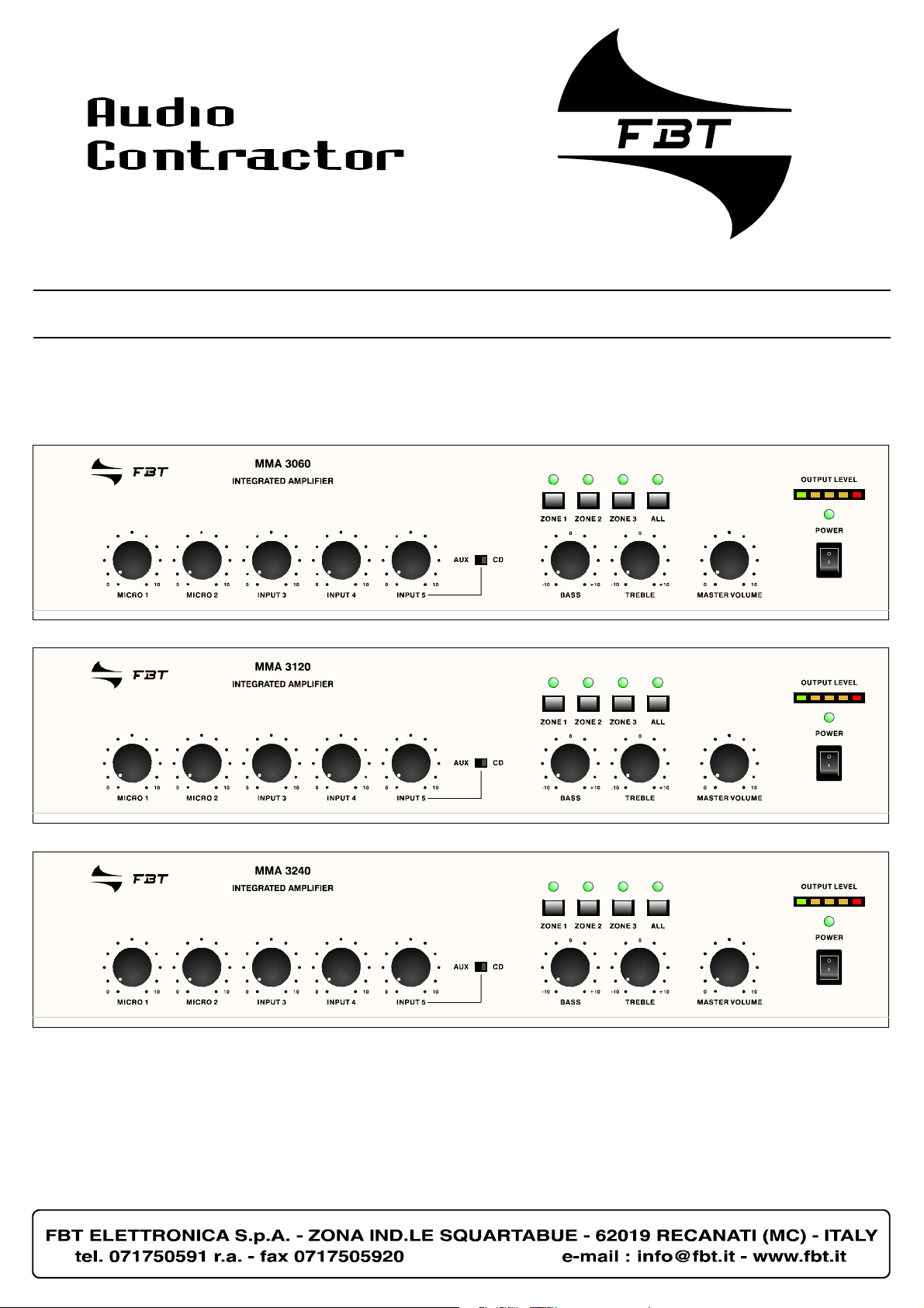
MMA3060
MMA3120
MMA3240
Istruzioniperl’uso
Instructionsforuse
Manueld’utilisation
Gebrauchsanleitung
Gebruiksaanwijzing
Instruccionesdeempleo
Page 2

LaFBTsiriservaildirittodiapportaremodificheaidisegnieallecaratteristichetecnicheinqualsiasimomentoesenzapreavviso.
FBTreservetherighttomakechangestothedrawingsandtechnicalspecificationsatanytimeandwithoutnotice.
FBTseréserveledroitd’apporterdesmodificationsauxdessinsetcaractéristiquestechniquesàtoutinstantetsanspréavisaucun
FBTdasRechtvor,jederzeitundohneVorankündigungÄnderungenantechnischenZeichnungenund-Merkmalenvorzunehmem.
FBTbehoudtzijzichhetrechtvooropiedermomentzondervoorberichtdetekeningenentechnischeeigenschappenaan wijzigen
teonderwerpen.
FBTsereservaelderechodemodificarlosdibujosylascaracterísticastécnicassinpreavisoalguno.
Page 3

1
TABLEOFCONTENTSSOMMARIO SOMMAIRE
SOMMARIO
1.Descrizionegenerale
1.1Pannellofrontale ..............................3
1.2Pannelloposteriore ..........................3
2.Avvertenzegenerali
2.1Installazione ....................................4
2.2Alimentazione ...................................4
2.3Notedisicurezza ..............................4
3.Connessioni
3.1Criterigenerali .................................5
3.2Ingressimicrofonici ..........................5
3.3IngressiMIC/LINE ............................5
3.4Ingressiausiliari ...............................6
3.5Ingressotelefonico ..........................6
3.6Uscita‘MusicOnHold’(MOH) ............7
3.7Precedenzamicrofonica
esegnaledipreavviso .....................7
3.8Uscitedipotenza .............................8
3.8.1Sistemiabassaimpedenza ...............8
-Calcolodell’impedenza
neicollegamentiinserie .................8
-Calcolodell’impedenza
neicollegamentiinparallelo ............8
3.8.2Sistemiatensionecostante ..............9
-Calcolodelnumero
didiffusori(tramitelepotenze) ......9
-Calcolodelnumero
di diffusori (tramite le impedenze)..9
3.9Uscitaregistratore/booster
epresaequalizzatore .......................9
3.10 Selezionedizoned’ascolto .............10
4.Usodell’apparecchio
4.1Accensione ....................................11
4.2Controllodivolumeprincipale .........11
4.3Correzioneacustica .......................11
-Controllotonibassi(BASS) ...........11
-Controllotoniacuti(TREBLE) ........11
4.4Sovraccaricoeprotezione ..............11
5.Caratteristichetecniche ......... 12
TABLEOFCONTENTS
1.Generaldescription
1.1Frontpanel ......................................3
1.2Rearpanel .......................................3
2.Generalwarnings
2.1Installation .......................................4
2.2Powersupply ...................................4
2.3Safetynotes ....................................4
3.Connections
3.1Generalfeatures ..............................5
3.2Microphoneinputs ............................5
3.3MIC/LINEinputs ...............................5
3.4Auxiliaryinputs ................................6
3.5Telephoneinput ...............................6
3.6’MusicOnHold’output(MOH) ...........7
3.7Microphonepriority
andwarningsignal ...........................7
3.8Poweroutputs .................................8
3.8.1Low-impedancesystems ...................8
-Calculatingtheimpedance
valueinseriesconnections ............8
-Calculatingtheimpedance
valueinparallelconnection ............8
3.8.2 Constantvoltagesystems ...............9
-Determiningthenumberof
speakers (through power values)..9
-Determiningthenumberof
speakers(throughimpedance) .......9
3.9Recorder/boosteroutput
andequalisersocket ........................9
3.10 Selectingthelisteningareas ...........10
4.Operation
4.1Poweron .......................................11
4.2Mastervolumecontrol ....................11
4.3Acousticadjustment .......................11
-Basscontrol(BASS) .....................11
-Treblecontrol(TREBLE) ...............11
4.4Overloadingandprotection ............11
5.Technicalspecifications .......... 12
SOMMAIRE
1.Descriptiongénérale
1.1Panneaufrontal .............................13
1.2Panneaupostérieur .......................13
2.Précautionsgénérales
2.1Installation .....................................14
2.2Alimentation ...................................14
2.3Conseilsdesecurite .......................14
3.Connexions
3.1Criteresgeneraux ..........................15
3.2Entréesmicro .................................15
3.3EntréesMIC/LINE ..........................15
3.4Entréesauxiliaires ..........................16
3.5Entréetéléphonique .......................16
3.6Sortie‘MusicOnHold’(MOH) ..........17
3.7Prioritémicroet
signald’annonce ............................17
3.8Sortiesdepuissance ......................18
3.8.1Systèmesàbasseimpédance .........18
-Calculdel’impédancesur
lesbranchementsensérie ...........18
-Calculdel’impédancesur
lesbranchementsenparallèle ......18
3.8.2Systèmesàtensionconstante ........19
-Calculdunombrede
diffuseurs(parlespuissances) .....19
-Calculdunombrede
diffuseurs (par les impedances)...19
3.9Sortieenregistreur/booster
etpriseegaliseur ...........................19
3.10 Selectiondezonesd’ecoute ...........20
4.Utilisationdel’appareil
4.1Miseenmarche ..............................21
4.2Controledevolumeprincipal ..........21
4.3Correctionacoustique ....................21
-Contrôletonalitébasses(BASS)...21
-Contrôletonalitéaigues(TREBLE).21
4.4Surchargeetprotection .................21
5.Caractéristiquestechniques... 22
Schemaablocchi ............................... 33
Blockdiagram ..................................... 33
Schémafonctionnel ........................... 33
Page 4

2
INHOUDINHALTSANGABE SUMARIO
INHALTSANGABE
1.AllgemeineBeschreibung
1.1Frontpaneel ...................................13
1.2Rückpaneel ....................................13
2.AllgemeineHinweise
2.1Installation .....................................14
2.2Einspeisung ....................................14
2.3Sicherheitsanweisungen .................14
3.Anschlüsse
3.1AllgemeineHinweise .......................15
3.2Mikrofoneingänge ..........................15
3.3EingängeMIC/LINE ........................15
3.4Hilfseingänge .................................16
3.5Telefoneingang ..............................16
3.6Ausgänge‘MusicOnHold’(MOH)....17
3.7Mikrofonvorrangund
Vorankündigungssignal ...................17
3.8Leistungausgänge ..........................18
3.8.1SystemmitniedrigerImpedanz .......18
-BerechnungderImpedanz
beiReihenschaltungen .................18
-BerechnungderImpedanz
beiParallelschaltungen ................18
3.8.2SystememitkonstanterSpannung..19
-Berechnungderlautsprecheranzahl
(durch die leistungen)...................19
-Berechnungderlautsprecheranzahl
(durch die impedanzen)................19
3.9AusgangAufnahmegerät/Booster
undBuchseEqualizer .....................19
3.10 AuswahlderKlangzone ..................20
4.GebraüchdesGerates
4.1Einschalten ....................................21
4.2SteuerungderHauptlautstärke ......21
4.3Tonkorrektur ..................................21
-Tiefenkontrolle(BASS) .................21
-Kontrollehohetöne(TREBLE) ......21
4.4ÜberlastungundSchutz .................21
5.TechnischeEigenschaften ...... 22
INHOUD
1.Algemenebeschrijving
1.2Frontpaneel ...................................23
1.2Achterpaneel .................................23
2.Algemeneaanwijzingen
2.1Installatie ......................................24
2.2Voeding ..........................................24
2.3Opmerkingenoverdeveiligheid ......24
3.Aansluitingen
3.1Algemenecriteria ...........................25
3.2Microfooningangen ........................25
3.3MIC/LINEingangen ........................25
3.4Hulpingangen .................................26
3.5Telefooningang ...............................26
3.6Uitgangen‘MusicOnHold’(MOH)....27
3.7Microfoonvoorrangen
waarschuwingssignaal ....................27
3.8 Vermogensuitgangen ...................... 28
3.8.1Systemen met een lage impedantie.28
-Berekeningvandeimpedantie
bijserieschakeling ........................28
-Berekeningvandeimpedantie
bijparallelschakeling ....................28
3.8.2 Constantespanningssystemen .......29
-Berekeningvanhetaantal
klankverspreiders (via de kracht).29
-Berekeningvanhetaantal
klankverspreiders (via de impedanties)29
3.9Uitgangrecorder/booster
enaansluitingequalizer ..................29
3.10 Selectievanluisterzones ................30
4.Gebruikvanhetapparaat
4.1Aanzetten ......................................31
4.2Hoofdvolumeregeling .....................31
4.3Akoestischecorrectie .....................31
-Regelinglagetonen(BASS) .........31
-Regelinghogetonen(TREBLE)...31
4.4Overbelastingenbeveiliging ..........31
5.Technischekenmerken ........... 32
SUMARIO
1.Descripcióngeneral
1.2Panelfrontal ..................................23
1.2Paneltrasero .................................23
2.Advertenciasgenerales
2.1Instalación .....................................24
2.2 Alimentación ..................................24
2.3Notas para la seguridad..................24
3.Conexiones
3.1Criterios generales.........................25
3.2Entradasmicrofónicas ....................25
3.3EntradasMIC/LINE ........................25
3.4Entradasauxiliares ........................26
3.5Entradatelefónica .........................26
3.6Salidas’MusicOnHold’(MOH) ........27
3.7Precedenciamicrofónica
yseñaldepreaviso ........................27
3.8Salidasdepotencia ........................28
3.8.1Sistemasconbajaimpedancia ........28
-Cálculodelasimpedancias
enlasconexionesenserie ...........28
-Cálculodelasimpedancias
enlasconexionesenparalelo ......28
3.8.2Sistemasdetensiónconstante .......29
-Cálculodelnœmerodedifusores
(mediantelaspotencias) .............29
-Cálculodelnúmerodedifusores
(mediantelasimpedancias) ..........29
3.9Salidagrabadora/booster
ytomaecualizador .........................29
3.10 Seleccióndezonasdeescucha.......30
4.Usodelaparato
4.1 Encendido ...................................... 31
4.2Controldevolumenprincipal ..........31
4.3Correcciónacústica ........................31
-Controltonosbajos(BASS) ..........31
-Controltonosagudos(TREBLE)...31
4.4Sobrecargayprotección ................31
5.Característicastécnicas ......... 32
.....
Blockschema ....................................... 33
Blokschema ........................................ 33
Esquemadebloques .......................... 33
Page 5
3
DESCRIZIONEGENERALE GENERALDESCRIPTION
12
OUTPUTLEVEL
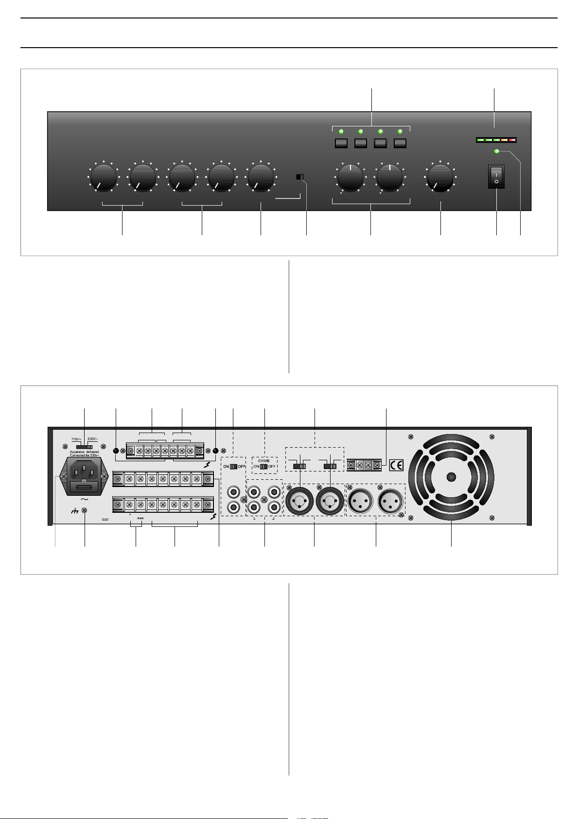
1.1PANNELLOFRONTALE
[1] Selettoridellezone.
[2] Visualizzatoredellivellodiuscita.
[3] Spiad’accensione.
[4] Interruttoredirete.
[5] Controllodivolumegenerale.
[6] Controlliditono.
[7]Selettoreingressiausiliari.
[8]Controllolivelloingressoausiliario.
[9]Controllidilivelloingressi3e4.
[10 ]Controllidilivelloingressimicrofonici.
111215161718191314
ZONE1ZONE3ZONE2ALL
0
AUXCD
+1010101010101000000
INPUT3INPUT4MICRO1MICRO2
INPUT5
BASS
0
TREBLE
+1010
0
MASTERVOLUME
10
POWER
456910873
1.1FRONTPANEL
[1] Zoneselectionswitches.
[2] Outputlevelindicator.
[3] ON/OFFsignallinglamp.
[4] Mainsswitch.
[5] Generalvolumecontrol.
[6] Tonecontrols.
[7]Auxiliaryinputsselectorswitch.
[8]Auxiliaryinputlevelcontrol.
[9]Inputs3and4levelcontrol.
[10] Levelcontrolformicrophoneinputs.
GCOMHOT
8 Ω
1V1W
600Ω
LINK
PREOUT
POWERIN
FUSET6,3A
CONSUMPT.200W
CONSUMT.200W
MOHOUTPUTTEL
COMCOMCOMVINZ2Z3Z1
24VCOM50V70V100V
8Ω
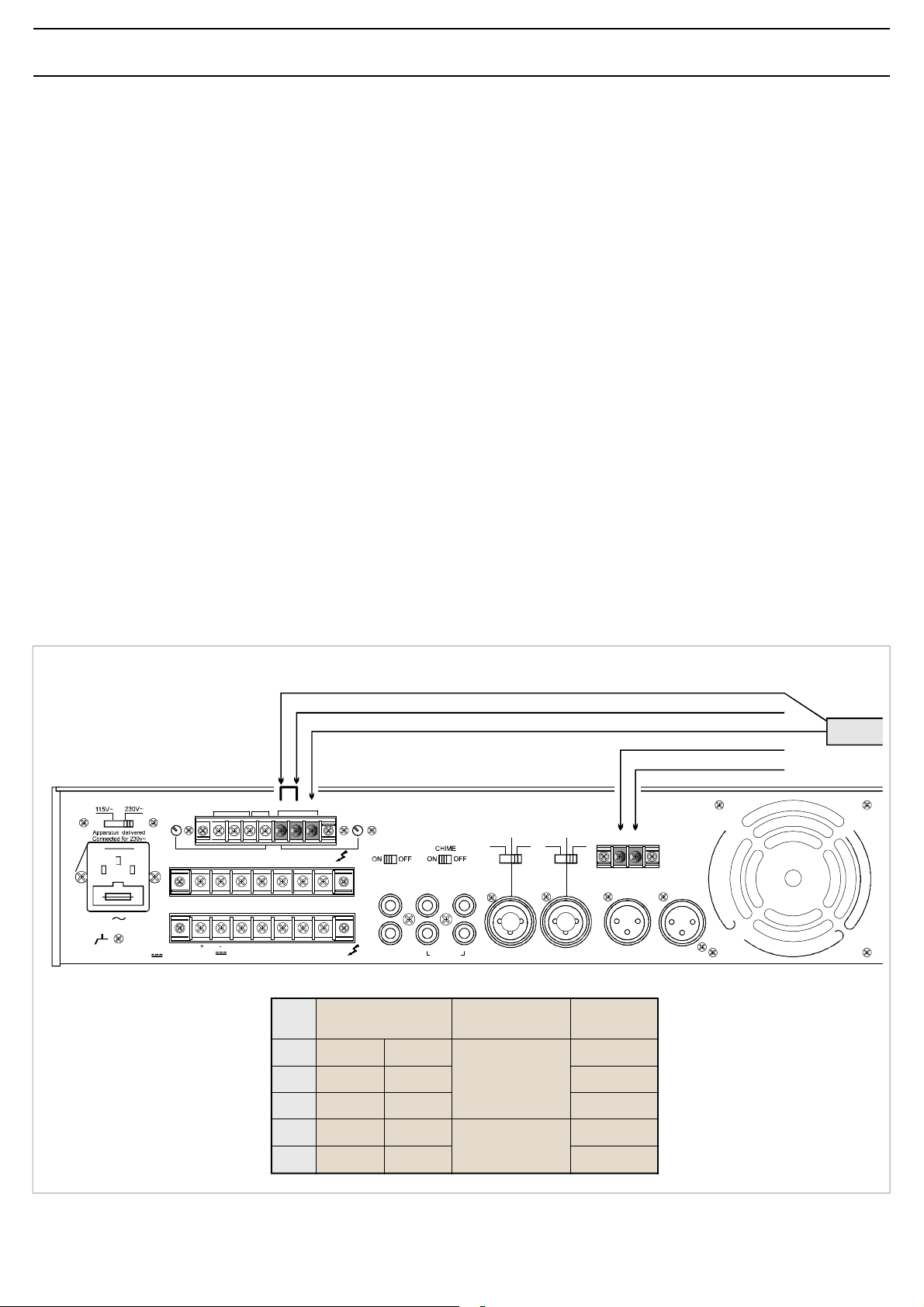
1.2PANNELLOPOSTERIORE
[11] Selettoredellatensionedirete.
[12] RegolazionelivellouscitaMUSICONHOLD.
[13] Uscitedilineaedipotenza(1W/8Ω)MUSICONHOLD.
[14] Ingressotelefonicobilanciato.
[15] Regolazionelivelloingressotelefonico.
[16]Presaperequalizzatoreesterno.
[17 ]ChimeON/OFF.
[18 ]Selettorimodalitàfunzionamentoingressi3e4.
[19] Morsettierapercontattodiprecedenza.
[20 ]Presadiaerazioneventoladiraffreddamento.
[21 ]Ingressimicrofonicibilanciati.
[22 ]IngressiMIC/LINE.
[23 ]Ingressiausiliari.
[24] Morsettieraperzoneselezionate.
[25] Morsettierauscitealtoparlanti.
[26 ]Morsettieraperalimentazioneesternaincorrentecontinua.
[27 ]Connessionetelaio.
[28 ]Spinadireteconfusibileincorporato.
PHANTOM
LINE
AUXCD
INPUT5INPUT4INPUT3MICRO2MICRO1
PHANTOM
LINE
MIC
MIC
+
PRIORITY
P
1.2REARPANEL
[11] Mainsvoltageselectorswitch.
[12] MUSICONHOLDoutputleveladjustment.
[13] MUSICONHOLDlineandpoweroutputs(1W/8).Ω
[14] Balancedtelephoneinput.
[15] Telephoneinputleveladjustment.
[16]Socketforanexternalequaliser.
[17]ChimeON/OFF.
[18]Inputs3and4modeselectorswitches.
[19] Terminalstripforprecedencecontact.
[20]Coolingfanairintake.
[21] Balancedmicrophoneinputs.
[22]MIC/LINEinputs.
[23] Auxiliaryinputs.
[24] Terminalstripforselectedzones.
[25] Loudspeakeroutputterminalstrip.
[26 ]TerminalstripforexternalDCpowersupply.
[27 ]Frameconnection.
[28 ]Mainsplugwithbuilt-infuse.
202122232425262728
Page 6
4
AVVERTENZEGENERALI GENERALWARNINGS
2.1INSTALLAZIONE
TuttigliapparecchiFBTsonocostruitinelrispettodellepiøsevere
normativeinternazionalidisicurezzaedinottemperanzaairequisiti
dellaComunitàEuropea.Peruncorrettoedefficaceusodell’apparecchio
èimportanteprendereconoscenzadituttelecaratteristicheleggendo
attentamentelepresentiistruzioniedinparticolarelenotedisicurezza.
Duranteilfunzionamentodell’apparecchioènecessarioassicurare
un’adeguataventilazione.Evitarediracchiuderel’apparecchioinun
mobileprivodiaerazioneodiostruirelefessurediventilazioneedin
particolarelapresad’ariaposterioredellaventoladiraffreddamento.
Evitareinoltreditenerel’apparecchioinprossimitàdisorgentidicalore.
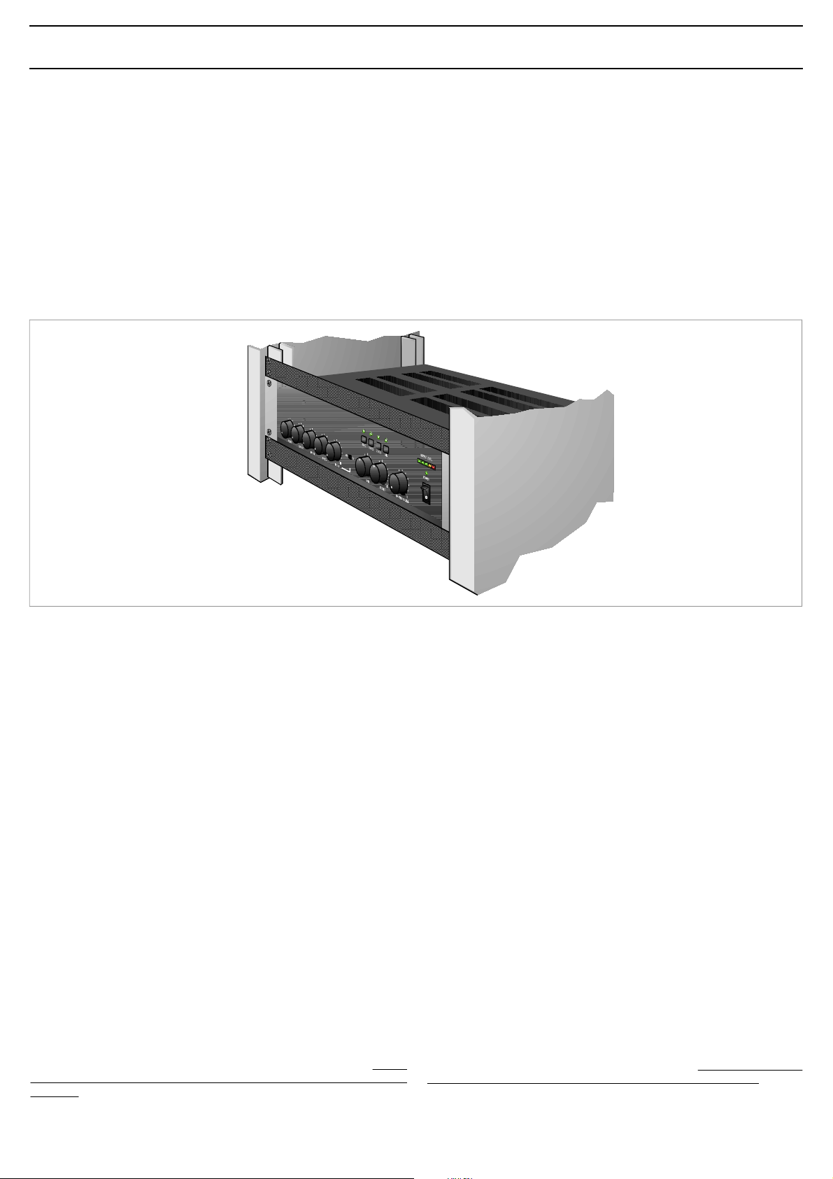
Questoapparecchioèpredispostoperilmontaggioinmobilerackstandard
19”.
Siconsigliadiinterporreunpannellodiaerazionetraunapparecchioe
l’altro(vedifig.2.1.1).
2.1INSTALLATION
AllFBTequipmentismanufacturedinaccordancewiththemost
stringentinternationalsafetystandardsandincompliancewithEuropean
Communityrequisites.Inordertousetheequipmentcorrectlyand
effectively,itisimportanttobeawareofallitscharacteristicsbyreading
theseinstructionsandinparticularthesafetynotescarefully.
Whiletheequipmentisworking,itisnecessarytoprovideadequate
ventilation.Donotclosethisequipmentinsideanunventilatedcabinet
anddonotobstructtheairvents,inparticularnottheairintakeonthe
rearforthecoolingfan.
Donotkeeptheequipmentinthevicinityofsourcesofheat.
Thisequipmentcanbeequippedformountinginastandard19”.
Itisrecommendedthatyouplaceaventilationpanelbetweenone
pieceofequipmentandthenext(seeFigure2.1.1).
Fig.2.1.1
2.2ALIMENTAZIONE
Questoapparecchioèpredispostoperilfunzionamentocontensionedi
retea230V–10%50/60Hz.¨possibileutilizzarel’apparecchioanche
conunatensionediretedi115V–10%50/60Hz;atalscopoè
necessarioportareilselettore[11 ]inposizione“115V”.
Gliamplificatoridella Serie5000 possono ancheesserealimentaticon
unasorgenteesternadicorrentecontinuacontensionedi24Vche
deveessereapplicata,rispettandolepolarità,airelativiterminalidella
morsettiera[26].Inaccordoconlenormativedisicurezza,l’interruttore
diaccensione[4]agiscesolosullatensionedirete.
Indotazioneall’apparecchioèfornitouncavodialimentazioneconfilo
diterra;ilterminalediterradellaspinadiretenondeveessererimosso
inalcuncaso.
Collegarelaspinadirete[28]dell’apparecchioallareteelettrica
utilizzandol’appositocavofornitoindotazione;assicurarsichelapresa
dicorrentesiadotatadicollegamentoditerraanormadilegge.
L’apparecchioèprotettodaduefusibili(vedipar.4.4).
2.3NOTEDISICUREZZA
Ogniinterventoall’internodell’apparecchio,qualelaselezionedialcuni
modid’usoolasostituzionedifusibili,deveessereeffettuatosoloda
personalespecializzato:larimozionedelcoperchiorendeaccessibili
particonrischiodiscosseelettriche.
Primadirimuovereilcoperchioaccertarsisemprecheilcavodiretesia
staccato.
Nelcasodiaccidentalecadutadiliquidisull’apparecchio,staccare
immediatamentelaspinadireteedinterpellareilcentrodiassistenza
FBTpiùvicino.
Laconnessioneditelaio[27]consentedicollegarealtreapparecchiature
perlasolafunzionedischermaturadeisegnaliabassolivello: questa
presanondeveessereutilizzataperilcollegamentodisicurezzadeltelaio
allaterra.
2.2POWERSUPPLY
Thisequipmentisdesignedforusewithamainsvoltageof230V–10%
50/60Hz.Itisalsopossibletousetheequipmentwithamainsvoltage
of115V–10%50/60Hz,howeverinthiscaseitisnecessaryto
positiontheselectorswitch[11 ]on“115V”.
Theamplifiersofthe 5000Series canalsobepoweredbymeansofan
externalDCpowersupplywithavoltageof24V,whichhastobeapplied
totheappropriateterminalsontheterminalstrip[ 26]payingattention
tothecorrectpolarity . Asrequiredundersafetyregulations,the
ON/OFFswitch[4]onlycontrolsthemainsvoltage.
Theequipmentissuppliedwithitsownpower-supplycable,whichis
equippedwithanearthingwire.Theearthterminalofthemainsplug
shouldneverberemovedunderanycircumstances.
Connectthemainsplug[28]oftheequipmenttothepowermainsusing
thecableincludedinthesupply.Makesurethatthepoweroutletis
equippedwithaconnectiontoearthinaccordancewiththelaw.
Theequipmentisprotectedbytwofuses(seepoint4.4).
2.3SAFETYNOTES
Anyactivitiesinsidetheapparatus,suchasselectingsomeofthe
operatingmodes,theinstallationofaccessoriesorthereplacement
offuses,mustbecarriedoutbyspecializedpersonnelonly:whenthe
coverisremoved,partsliabletocauseelectricshocksareexposed.
Beforeremovingthecover,alwaysmakesurethatthepowercord
hasbeendisconnected.
Intheeventthatliquidisaccidentallyspiltontotheapparatus,
disconnectthemainsplugimmediatelyandcontactthenearestFBT
ServiceCentre.
Thechassisconnection[27]maybeusedtoconnectotherequipment
onlyforthepurposeofshieldingthelowsignals: thissocketmaynot
beusedtoconnectthechassistoearthforsafetypurposes.
Page 7
5
CONNESSIONI CONNECTIONS
3.1CRITERIGENERALI
Peruncorrettofunzionamentodell’apparecchioèopportunoosservare
alcunicriteridimassimanell’esecuzionedeicollegamenti:
•evitareilposizionamentodicaviedimicrofonisulmobile
dell’apparecchio.
•evitaredistenderelelineedisegnaleparalleleaquelledirete;
osservareunadistanzaminimadi30/40cm.
•posizionarelelineediingressoelelineediuscitadistantitraloro.
•posizionareimicrofonialdifuoridell’angolodiradiazionedeidiffusori
sonoriperevitareilfenomenodireazioneacustica(effettoLarsen).
3.2INGRESSIMICROFONICI
AllepreseXLR“MICRO1”e“MICRO2”[21]èpossibilecollegare
microfoniPASOditipodinamicoead elettreteconalimentazionephantom;
icollegamentiaquestepresesonoriportatinellaFig.3.2.1.
Ulterioripossibilitàdiconnessione,chesfruttanol’usodellamorsettiera
PRIORITY [19],sonoriportatealpar.3.7.
Ogniingressomicrofonicodisponediunpropriocontrollodilivello[ 10]
perdosareopportunamentel’ampiezzadeivarisegnali.
L’ingressomicrofonico“MICRO1”dispone,inoltre,dellafunzionedi
precedenzaautomatica(VOX): parlandoalmicrofonocollegatoaquesto
ingressoverrannoautomaticamenteammutolitigliingressi ausiliarie
l’ingresso“INPUT4”(seselezionato,vedipar.3.3);illivellodella soglia
diattivazionedelcircuitodiprecedenzaautomaticanonèdipendente
dallaposizionedelcontrollo“MICRO1”[10].
Gliingressimicrofonici[21]sonodotatidialimentazionePhantomper
microfonielettrete12/24V.
Incasosivolessedisinserirel’alimentazionePhantom,agiresuiponticelli
SW201 - SW202 situatisulcircuitoingressi(v edipar.2.3).
3.1GENERALFEATURES
Forproperunitoperation,usethefollowinginstructionswhenmaking
theconnections:
•Donotplacecablesormicrophonesontheunitcabinet;
•Donotlaysignallinesparalleltopowerlines;ensureaminimum
distanceof30/40cmbetweenthem;
•Keepinputlinesandtheoutputlinesfarapart;
•Keepthemicrophonesoutsidetheoperatingspanofthespeakersto
avoidacousticfeedback(Larseneffect).
3.2MICROPHONEINPUTS
ItispossibletoconnectPASOmicrophonesofthedynamicoroftheelectret
typewithaphantompowersupplytotheXLRsockets“MICRO1”and
“MICRO2”[21].
TheconnectionstothesesocketsareshowninFigure3.2.1.
Furtherpossibleconnectionsexploitingthe PRIORITY terminalstrip
[19]areindicatedunderpoint3.7.
Eachmicrophoneinputhasitsownlevelcontrol[10]sothatthe
amplitudeofthevariousdifferentsignalscanbesuitablyadjusted.
The“MICRO1”microphoneinputalsohasanautomaticpriority
function(VOX).Whenspeakingwiththemicrophoneconnectedtothis
input,theauxiliaryinputsand“ INPUT4”willbeautomaticallymuted
(ifselected,seepoint3.3).Thelevelofthethresholdforactivating
theautomaticprioritycircuitdoesnotdependonthepositionofthe
“MICRO1”control[10].
Themicrophoneinputs[21]haveaphantompowersupplyfor12/24V
electretmicrophones.Toexcludethephantompowersupply,use
jumpers SW201 and SW202 ontheinputcircuit(seepoint2.3).
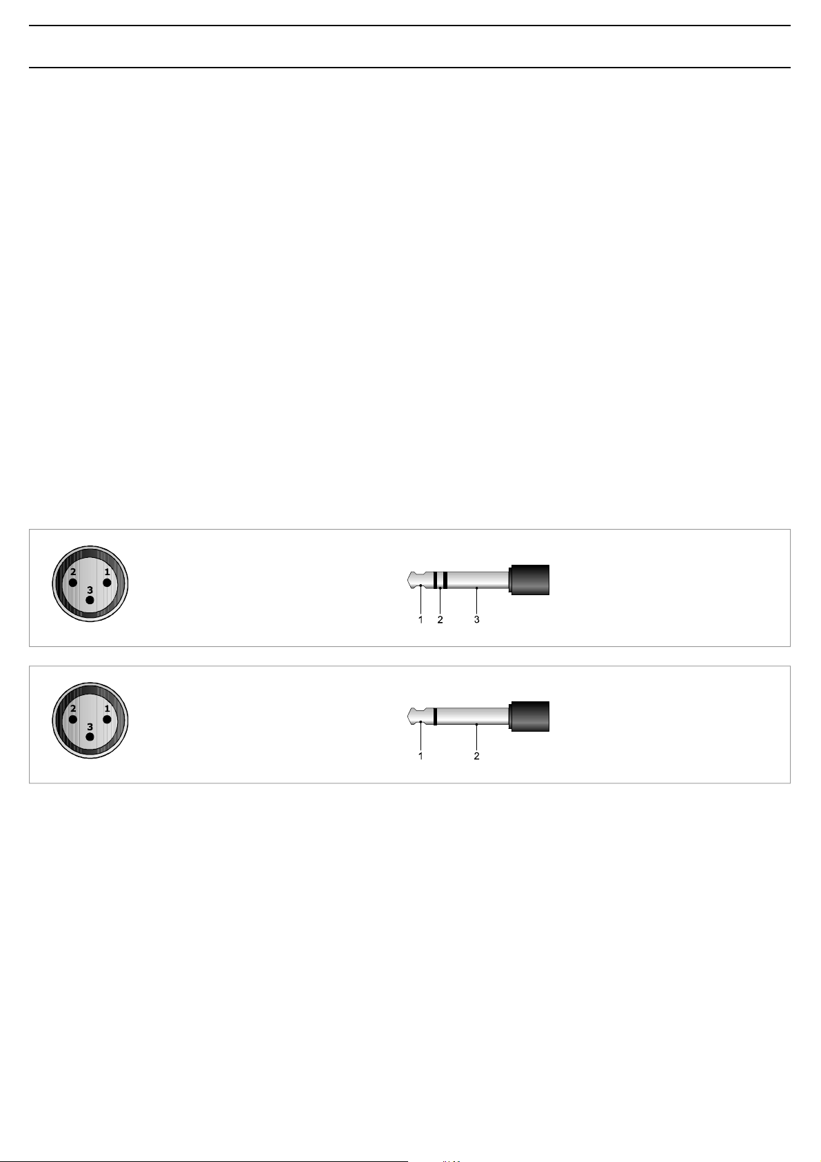
COLLEGAMENTOBILANCIATO-BALANCEDCONNECTION
1 =schermo/shield
2 =segnale(latocaldo)/signal(hotside)
3 =segnale(latofreddo)/signal(coldside)
COLLEGAMENTOSBILANCIATO-UNBALANCEDCONNECTION
1 =schermoemassa/shieldand GND
2 =schermoemassa/shieldand GND
3 =segnale/signal
Fig.3.2.1
3.3INGRESSIMIC/LINE
Leprese“INPUT3”ed“INPUT4”[22]sonoconfigurabiliinmodo
indipendentecomeingressimicrofonici(conosenzaalimentazione
phantom)ocomeingressidilinea.Laselezionedellamodalitàèottenuta
tramiteideviatoriatreposizioni[18 ]:
•inposizioneMIC,siselezionalasensibilitàmicrofonicaconalimentazione
phantomdisattivata;
•inposizionePHANTOM,siselezionalasensibilitàmicrofonicaattivando
l’alimentazionephantom(permicrofonielettrete12/24V);
•inposizioneLINE,siselezionalasensibilitàdilinea.
ÉpossibileeffettuareilcollegamentosiaconspineditipoXLRmaschioche
conspinottojack1/4”.Icol legamentiaquestepresesonoriportati
nellaFig.3.2.1.
Ogniingressodisponediunpropriocontrollodilivello[9]perdosare
opportunamentel’ampiezzadeivarisegnali.
L’ingresso“INPUT4”puòessereassoggettatoomenoallaprecedenza
automatica(VOX)dell’ingresso“MICRO1” edallachiusuradelcontatto
diprecedenzaPRIORITY.Incasosivolessedisinserirequestafunzione,
agiresulponticello SW207 postosulcircuitoingressi(vedipar.2.3).
1 =segnale(latocaldo)/signal(hotside)
2 =segnale(latofreddo)/signal(coldside)
3 =schermo/shield
1 =segnale/signal
2 =schermoemassa/shieldand GND
3.3MIC/LINEINPUTS
The“INPUT3”and“INPUT4”sockets[22]canbeseparately
configuredasmicrophoneinputs(withorwithoutphantompowersupply)
oraslineinputs.
Themodesareselectedbymeansofthethree-positionswitches[18]:
•intheMICpositionthesensitivityofthemicrophonewiththephantom
powersupplyde-activatedisselected;
•inthePHANTOMpositionthesensitivityofthemicrophonewiththe
phantompowersupplyactivated(for12/24Velectretmicrophones)is
selected;
•intheLINEpositionthesensitivityofthelineisselected.
ItispossibletomaketheconnectionseitherwithmaleXLRplugsorwith
1/4”jacks.TheconnectionstothesesocketsareshowninFigure3.2.1.
Eachinputhasitsownlevelcontrol[9]soastobeabletoadjustthe
amplitudeofthevariousdifferentsignalssuitably.
“INPUT4”canbesubjectedorotherwisetoautomaticpriority(VOX)on
thepartofthe“MICRO1”inputandtoclosingofthePRIORITYcontact.
Intheeventthatyouwishtode-activatethisfunction,usejumper
SW207 situatedontheinputcircuit(seepoint2.3).
Page 8
6
CONNESSIONI CONNECTIONS
3.4INGRESSIAUSILIARI
Allepresephono“AUX”e“CD”[23]èpossibilecollegareduesorgenti
musicaliadaltolivello(lettoredicompactdisc,riproduttoreanastro,
sintonizzatore,radioricevitorepermicrofonisenzafilo,ecc.).
Ladoppiapresaconsenteunvelocecollegamentodellasorgente
all’amplificatoretramitecavettostereo:lamiscelazionedeiduecanali
destroesinistro(L/R)èrealizzatainternamente.
Laselezionedellasorgenteavvienetramitel’appositoselettore[7 ]posto
sulpannellofrontaledell’apparecchio.
Laregolazionedilivellodellasorgenteselezionatasieffettuatramiteil
controllo INPUT5 [8 ].
Lasorgenteselezionataèsoggettaall’ammutolimentosiaperprecedenza
automatica(VOX)degliingressi TEL e MICRO1 cheperlachiusuradel
contatto PRIORITY.
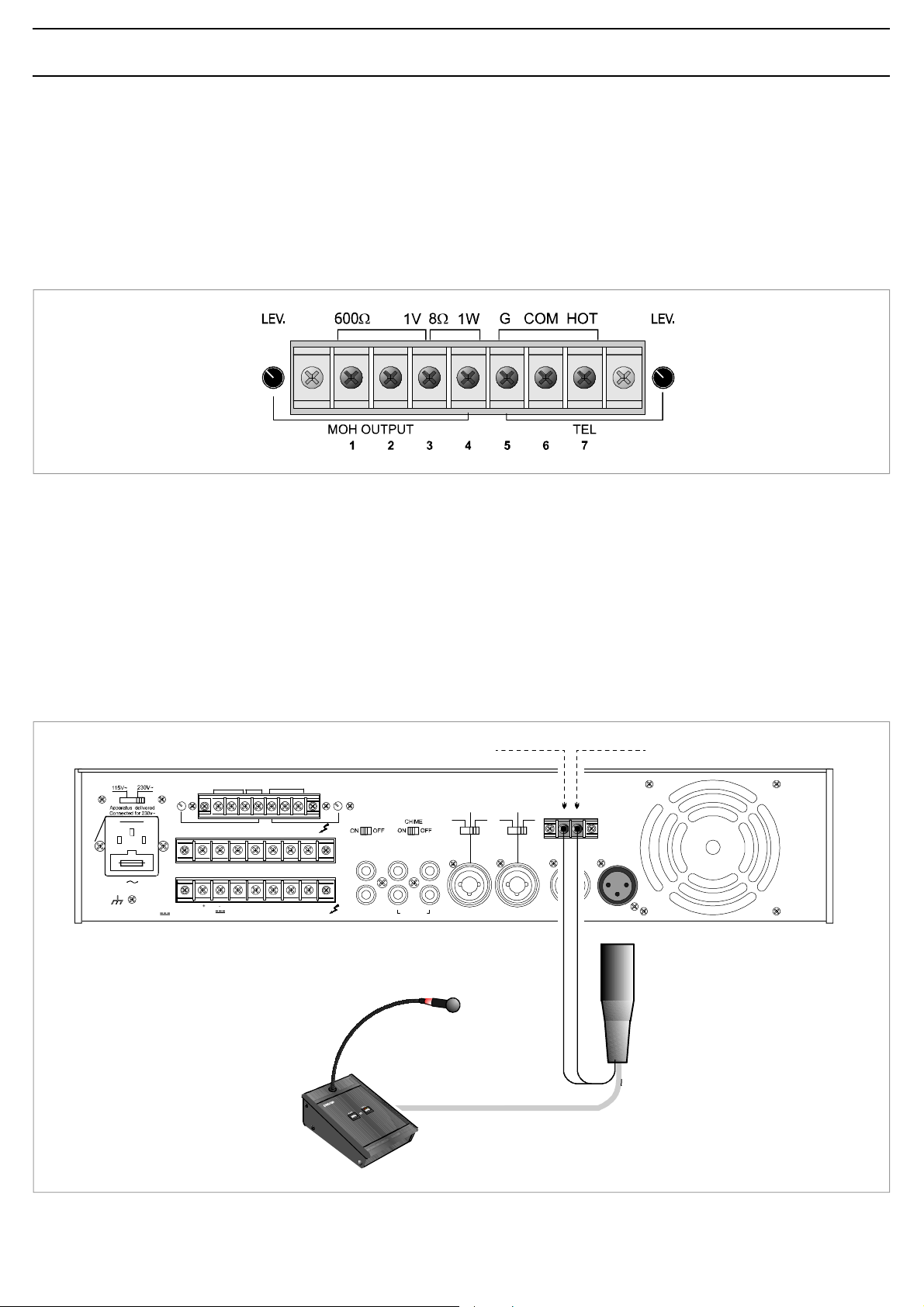
3.5INGRESSOTELEFONICO
L’apparecchioèpredispostoperilcollegamentoadunsistematelefonico
tramitelamorsettiera“TEL”[14].Taleingressoèbilanciatoa
trasformatore,possiedeunpropriocontrollodilivello-“ LEV.”[15 ]-edè
dotatodicircuitoVOXperladiffusionedeimessaggiconprioritàpiù
elevatarispettoaqualsiasialtroingresso.
L’ingressotelefonicoconsenteinoltreilcollegamentodell’apparecchioalle
basipreamplificate. Perquestoènecessariorimuovere
lospinottopentapolareDINdalcavodellabaseeconifilirealizzarei
collegamentiillustratiinfig.3.5.1.
IMPORTANTE :perquestotipodicollegamentoèINDISPENSABILE
chiuderetramiteunponticelloicontatti[G]e[COM]dellamorsettiera
“TEL”[14].
3.4AUXILIARYINPUTS
Itispossibletoconnecttwohigh-levelsourcesofmusic(CDplayer,tape
recorder,tuner,radio-receiverforwirelessmicrophones,etc.)tothe
“AUX”and“CD”[23]phonosockets.Thankstothefactthatthereare
twosockets,itiseasytoconnectthesourcerapidlytotheamplifierby
meansofastereocable:mixingofthetwochannels(leftandright-L/R)
iscarriedoutinternally.
Thesourceisselectedbymeansoftheselector[7]providedforthis
purposeonthefrontpaneloftheequipment.
Thelevelofthesourcethatisselectedcanbeadjustedbymeansofthe
INPUT5 control[8 ].
Thesourcethatisselectedissubjecttomutingbothasaresultof
automaticpriority(VOX)ofthe TEL and MICRO1 inputsanddueto
closingofthe PRIORITY contact.
3.5TELEPHONEINPUT
Theequipmenthasprovisionsforconnectionofatelephonesystemby
meansofthe“TEL”terminalstrip[ 14].
Thisinputisbalancedbyatransformer,hasitsownlevelcontrol-“ LEV.”
[15 ]-andisequippedwithaVOXcircuitforbroadcastingmessageswith
ahigherprioritylevelthananyotherinput.
Thetelephoneinputalsoenablestheequipmenttobeconnectedtothe
pre-amplifiedbases.Todothis,itisnecessaryto
removethefive-poleDINplugfromthecableonthebaseandusethe
wirestomaketheconnectionsillustratedinFigure3.5.1.
IMPORTANT :ForthistypeofconnectionitisESSENTIALtoclosethe
contacts[G ]and[COM]ofthe“ TEL”terminalstrip[14 ]withajumper.
FUSET6,3A
CONSUMPT.200W
CONSUMT.200W
GCOMHOT
8 Ω600
1V1W
Ω
MOHOUTPUTTEL
COMCOMCOMVINZ2Z3Z1
24VCOM50V70V100V
8Ω
1 OMREHCS DLEIHS
2 OREN KCALB [ MOC ]
3 OCNAIB ETIHW [ TOH ]
4 OSSOR DER
5 EDREV NEERG [P]
1
2
3
4
5
S.p.A.-ITALY
"LET"
PHANTOM
LINE MIC
AREITTESROM
PIRTSLANIMRET
"YTIROIRP"
PRIORITY
[G]
[+]
P
+
ELANIMRET
LANIMRET
PHANTOM
LINK
AUXCD
PREOUT
POWERIN
.SOP
INPUT5INPUT4INPUT3MICRO2MICRO1
OVAC
ELBAC
LINE MIC
Fig.3.5.1
Page 9
7
CONNESSIONI CONNECTIONS
3.6USCITA‘MUSICONHOLD’(MOH)
Aquestimorsetti[13]e’disponibileilsegnaledellasolasorgente
selezionatasull’INPUT5[7 ];talesegnalenone’soggettoall’azionedi
precedenzamicrofonicaotelefonica.Inparticolare,l’uscitabilanciataa
trasformatore(morsetti 1-2-3 difig.3.6.1)puo’essereutilizzataperil
pilotaggiodiunulterioreamplificatore,diuncentralinotelefonicood
altro;l’uscitadipotenza(morsetti3- 4 difig.3.6.1)e’ingradodipilotare
direttamenteunpiccoloaltoparlantemonitorda8Ω conpotenzamassima
di1W.
Épossibileregolareillivellodiuscitaagendosulcontrollo“LEV.”[12].
1: 600Ω (linea-latocaldo)
(line-warmside)
2: 600Ω (linea-latofreddo)
(line-coldside)
3:massaeschermo
GNDandshield
4:1W/8Ω uscitaaltoparlanti
loudspeakersoutput
Fig.3.6.1
3.7PRECEDENZAMICROFONICAESEGNALEDIPREAVVISO
Chiudendoicontattidellamorsettiera“PRIORITY”[19]vengono
ammutolitilasorgentemusicaleselezionatael’ingresso“INPUT4”(vedi
par.3.3);lachiusuradelcontattogeneraunsegnaledipreavvisoadue
toni(CHIME)quandoilselettore“CHIME ”[17]sitrovainposizione ON.
Épossibilemodificareillivellodelsegnaledipreavvisoagendosultrimmer
semifisso VR301 postosulcircuitoPriority(vedipar.2.3).
3.6‘MUSICONHOLD’OUTPUT(MOH)
Thesignalonlyofthesourceselectedon INPUT5 [7 ]isavailableon
theseterminals[13].Thissignalisnotaffectedbytheuseoftelephone
precedence.Inparticular,thebalancedtransformeroutput(strips 1-23,Fig.3.6.1)canbeusedtodriveanadditionalamplifier,atelephone
exchangeorotherequipment.Thepoweroutput(terminals3- 4 inFigure
3.6.1)iscapableofdrivingdirectlyasmall8 Ω monitoringloudspeaker
withamaximumoutputof1W.
Itispossibletoadjusttheoutputlevelbymeansofthe “LEV.”
control[12].
5:TEL(massaschermo)
(GND andshield)
6:TEL(ingresso-latofreddo)
(input-coldside)
7:TEL(ingresso-latocaldo)
(input-warmside)
3.7MICROPHONEPRIORITYANDWARNINGSIGNAL
Onclosingthecontactsofthe“PRIORITY ”terminalstrip[19]the
musicsourcethathasbeenselectedand“INPUT4 ”(seepoint3.3)are
muted.Closingthecontactcausesatwo-tonewarningsignal(CHIME)
tobegeneratedifthe“CHIME ”selector[17]isinthe ON position.
Itispossibletoalterthelevelofthewarningsignalbymeansofthe
semi-fixedtrimmer VR301 situatedonthePrioritycircuit(seepoint2.3).
FUSET6,3A
CONSUMPT.200W
CONSUMT.200W
1V1W GCOMHOT
8 Ω600
Ω
MOHOUTPUTTEL
COMCOMCOMVINZ2Z3Z1
24VCOM50V70V100V
8Ω
BIANCO/WHITEVERDE/GREEN
LEV.LEV.
LINK
PREOUT
AUXCD
INPUT5INPUT4INPUT3MICRO2MICRO1POWERIN
PHANTOM
LINE MIC
PHANTOM
LINE MIC
+
PRIORITY
S.p.A.-ITALY
P
Page 10
8
CONNESSIONI CONNECTIONS
3.8USCITEDIPOTENZA
Leuscitedipotenzaperidiffusorisonodisponibilisullamorsettiera[25].
¨possibilerealizzareunimpiantodidiffusionesonorautilizzandosia
diffusoriabassaimpedenza,siadiffusoridotatiditraslatoredilinea.
Inentrambiicasiilcaricocomplessivonondeveesseretaleda
sovraccaricarel’amplificatore:nonapplicarecioèdiffusoriogruppidi
diffusoriconimpedenzapiøbassadiquellanominaledellapresaalla
qualesonocollegati.Siraccomandainoltrediporreparticolareattenzione
alcalcolodelleimpedenzenelcasosidebbanorealizzareimpiantidi
diffusionemisti(abassaimpedenzaeatensionecostante).
Intabella3.8.1sonoriportatiivalorinominaliditensioneedimpedenza
perlediverseuscite.
Uscita
8 Ω
50V
70V
100V
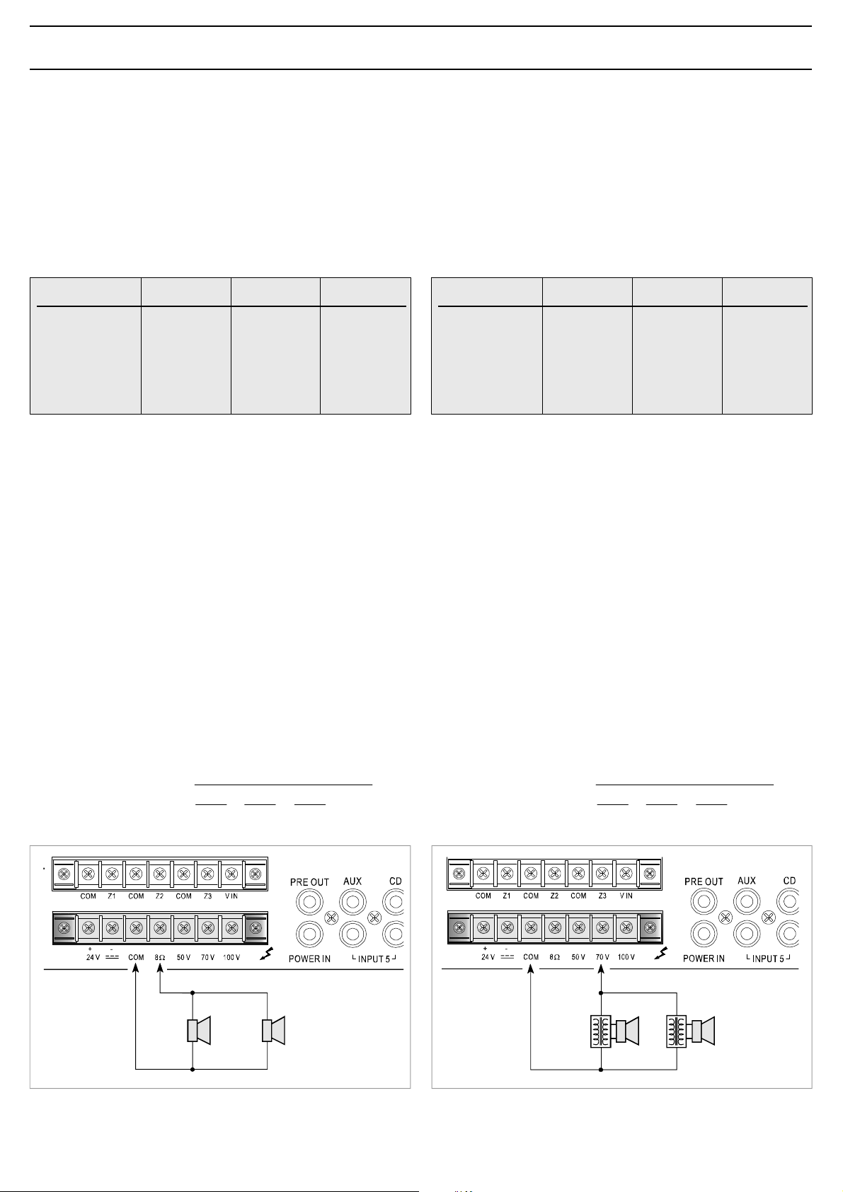
3.8.1 Sistemiabassaimpedenza
Inapplicazionicherichiedonol’usodipochialtoparlanti,lalineadi
collegamentopuòessereconnessatrailterminalecomune“0 ”elapresa
“8ΩΩΩΩΩ”dellamorsettiera[25].
Ilcollegamentodeglialtoparlanti,ditiposerieoparalleloomisto,deve
fornireun’impedenzacalcolatapariosuperioread8.Ω
Infigura3.8.1èriportatounesempiodicollegamento.
MMA3240
43,8V
10,4 Ω
20,4 Ω
41,7 Ω
Tabella3.8.1
MMA3120
31V
20,8 Ω
40,8 Ω
83,3 Ω
MMA3060
21,9V
41,7 Ω
81,6 Ω
167 Ω
3.8POWEROUTPUTS
Thepoweroutputsfortheloudspeakersareavailableontheterminal
strip[25 ].Itispossibletosetupasound-broadcastingsystem
usingeitherlow-impedanceloudspeakersorloudspeakersequippedwith
alinetransformer.Inbothcasestheoverallloadmustnotbesuchasto
overloadtheamplifier.Thismeansthatyoumustnotapplyloudspeakers
orgroupsofloudspeakerswithanimpedancelowerthantherated
impedanceofthesockettowhichtheyareconnected.Itisalso
necessarytopayparticularattentiontocalculatingtheimpedancevalues
ifmixedbroadcastingsystems(lowimpedanceandconstantvoltage)
aretobesetup.Table3.8.1showsvoltageandimpedanceratedvalues
forthevariousoutputs.
Output
8 Ω
50V
70V
100V
3.8.1 Low-impedancesystems
Inapplicationsthatrequiretheuseonlyofafewloudspeakers,the
connectinglinemaybeconnectedbetweenthecommonterminal“0 ”and
the“8 ΩΩΩΩΩ”socketoftheterminalstrip[ 25 ].
Theloudspeakerconnection,whetheroftheserialorparalleltypeor
mixed,shouldprovideanimpedancecalculatedtobeequaltoorhigher
than8Ω.AnexampleofaconnectionisshowninFigure3.8.1.
MMA3240 MMA3120 MMA3060
43,8V
10,4 Ω
20,4 Ω
41,7 Ω
Table3.8.1
31V
20,8 Ω
40,8 Ω
83,3 Ω
21,9V
41,7 Ω
81,6 Ω
167 Ω
•Calcolodell’impedenzaneicollegamentiinserie
Nelcasodidiffusoricollegatiinserietraloro,l’impedenzatotaleèla
sommadellesingoleimpedenze:
impedenzatotale = Z1 + Z2 + Z3+ ....
•Calcolodel l’impedenzaneicollegamentiinparallelo
Nelcasodidiffusoricollegatiinparallelotraloro,l’impedenzatotalepuò
esseredeterminatamediantelaseguenteformula:
impedenzatotale =
1
Z1
+
1
1
++......
Z2
1
Z3
•Calculatingtheimpedancevalueinseriesconnections
Inthecaseofloudspeakersconnectedtooneanotherinseries,thetotal
impedanceisthesumofthesingleimpedancevalues:
Totalimpedance = Z1 + Z2 + Z3+....
•Calculatingtheimpedancevalueinparallelconnections
Intheeventofloudspeakersconnectedinparalleltooneanotherthe
totalimpedancecanbecalculatedbymeansofthefollowingformula:
Totalimpedance =
1
Z1
+
1
1
++......
Z2
1
Z3
Fig.3.8.1
16ΩΩΩΩΩ16ΩΩΩΩΩ
20W20W
Fig.3.8.2
Page 11

9
CONNESSIONI CONNECTIONS
3.8.2 Sistemiatensionecostante
Nelcasodiimpianticonungrannumerodidiffusorie/ocondistanzetra
amplificatoriedaltoparlantimoltoelevateèpreferibileutilizzareunsistema
didistribuzioneatensionecostante(definitoancheadaltaimpedenza).
Inquestotipodiimpianto,idiffusori,provvistiditrasformatoridi
adattamentodiimpedenza,sonotutticollegatiinderivazioneallalinea
(vedies.diFig.3.8.2);questoparticolarerendedifacilerealizzazione
l’impiantoe,nelcasoincuiunaltoparlantedovesseperqualchemotivo
scollegarsidallalinea,ilrestodell’impiantoproseguirebbenelsuoregolare
funzionamento.Letensionicostantidisponibiliinuscitadall’amplificatore
sono 50, 70 e 100V.
•Calcolodelnumerodidiffusori(tramitelepotenze)
Sisuppongadiaveredefinitosial’amplificatore(cioèlasuapotenzadi
uscita)cheiltipodidiffusoreconrelativapotenzaassorbita.
Inquestocasoilmassimonumerodidiffusoricollegabilesullalineaè
determinatodallaseguenteformula:
numerodiffusori =
Esempio :siutilizzinounamplificatore MMA3240
L’amplificatoreèingradodierogareunapotenzaparia
240W,mentreundiffusoreassorbeunapotenzadi6W.
Persaperequantidiffusorisonocollegabiliallalineadiuscitasicalcola:
numerodiffusori = = 40
potenzaamplificatore
potenzadiffusore
240W
6W
3.8.2 Constantvoltagesystems
Whenalargenumberofspeakersisusedand/orthespeakersare
placedfarfromtheamplifiers,constantvoltagedistributionsystem
shouldbeused(alsoknownashigh-impedancesystems).
Inthistypeofsystem,thespeakersarefittedwithimpedance
adaptationtransformersandallofthemhaveshuntlineconnections
(seeexampleofFig.3.8.2).Thissimplifiesthelayoutofthesystemand
if,foranyreason,aloudspeakerisdisconnectedfromtheline,therest
ofthesystemwillcontinuetoworkproperly.Theconstantvoltages
outputfromtheamplifierare 50, 70 and 100V.
•Determiningthenumberofspeakers(throughpowervalues)
Ifboththeamplifier(i.e.itsoutputpower)andthetypeofspeaker
withitspowerconsumptionhavebeenestablished,themaximumnumber
ofspeakerswhichmaybeconnectedtothelinemaybedeterminedas
follows:
numberofspeakers =
Example :inasystemincludinga MMA3240 amplifier
theamplifiercansupply240Wpowerwhereas
thespeakerhasapowerconsumptionof6W.
Thenumberofspeakerswhichmaybeconnectedtotheoutputlineis
numberofspeakers = = 40
amplifierpower
speakerpower
240W
6W
•Calcolodelnumerodidiffusori(tramiteleimpedenze)
Seildatodisponibileèl’impedenzadeldiffusore,ilnumeromassimodi
diffusoricollegabiliadunalineaè:
numerodiffusori =
dovel’impedenzanominaledell’amplificatore è ricavabiledalla
tabella3.8.1.
Esempio :siutilizzinounamplificatore MMA3240 condiffusori
chepresentanounaimpedenzaparia500ohm.
Dallatabella3.8.1sitrovachel’impedenzanominaledicaricodellalinea
a100Vèparia41,7ohm.
Quindi:
•NOTABENE :nelcasopiùgeneraleincuiidiffusorisonodidiversotipo
e/ocollegaticondifferentepotenza,èimportanteverificaresempreche
lapotenzacomplessivarichiestadaidiffusori(ottenutasemplicemente
dallasommadellesingolepotenze)siainferioreaquellanominale
dell’amplificatore.
3.9USCITAREGISTRATORE/BOOSTEREPRESAEQUALIZZATORE
Neicasiincuifosserichiestaunaelaborazioneacusticadelsegnale,è
possibilecollegareunequalizzatore,odaltroelaboratoredisegnale,alle
prese POWERIN e PREOUT [ 16]dell’apparecchio.Perl’inserzione
dell’equalizzatore,l’interrutore LINK postosulretrodell’apparecchiodeve
esserenellaposizioneOFF.Questarealizzazionepermettelacorrezione
acusticadiambientiparticolarmenteriverberantielasoppressionedella
retroazioneacusticadiffusore-microfono(effettoLarsen).
Seall’amplificatorenonsonocollegate,tramiteleprese POWERIN e
PREOUT,apparecchiature esterne, l’interruttore LINK deveessere
postoinposizione ON permantenerelacontinuitàdellacatena
amplificatrice.
Allapresadiuscita PREOUT èdisponibileilsegnaledipilotaggiodella
partedipotenzacostituitodallamiscelazionedellediversesorgentiprima
delcontrollodivolumegenerale MASTERVOLUME [5 ].Talesegnale
puòessereutilizzatoperilpilotaggiodiunitàdipotenzae/oinviatoad
unapiastradiregistrazione.
numerodiffusori = = 12
impedenzadiffusore
impedenzaamplificatore
500 Ω
41,7 Ω
•Determiningthenumberofspeakers(throughimpedance)
Iftheimpedanceofthespeakerisknown,themaximumnumberof
speakerswhichmaybeconnectedtothelineis:
numberofspeakers =
wheretheamplifierratedimpedancemaybedeterminedreferringto
Table3.8.1.
Example :Ifa MMA3240 amplifierisusedwithspeakers
havinga500ohmimpedance,theratedloadimpedanceofthe
lineat100VmaybedeterminedfromTable3.8.1asbeingequalto
41,7ohm.
Thus
•N.B.: Inthemoregeneralcaseofasystemincludingloudspeakersof
differenttypesorconnectedwithdifferentoutputs,itisalwaysimportant
tomakesurethattheoverallpowerrequiredbytheloudspeakers(which
canbecalculatedsimplybyaddinguptheoutputpowerofthesingle
units)islowerthantheratedpoweroftheamplifier.
3.9RECORDER/BOOSTEROUTPUTANDEQUALISERSOCKET
Inthosecasesinwhichacousticprocessingofthesignalisrequired,it
ispossibletoconnectanequaliserorothersignalprocessingequipment
tothe POWERIN and PREOUT sockets[16]ontheequipment.
Wheninsertingtheequaliser,the LINK switchontherearofthe
equipmentmustbeinthe OFFposition.Thisapplicationenablesacoustic
correctionofroomssubjecttoparticularlyseverereverberationand
thesuppressionofacousticfeedbackbetweenloudspeakersand
microphones(Larseneffect).
Ifnoexternalequipmentisconnectedtotheamplifierbymeansofthe
POWERIN and PREOUT sockets,the LINK switchmustbeinthe ON
positioninordertomaintaincontinuityoftheamplifierchain.
Thesignaldrivingthepowerpartconsistingofthesignalresultingfrom
themixingofthevarioussourcesbeforethe MASTERVOLUME control
[5 ]isavailableonthe PREOUT outputsocket.Thissignalcanbeused
todrivepowerunitsand/orsenttoarecordingdeck.
numberofspeakers = = 12
speakerimpedance
amplifierimpedance
500 Ω
41,7 Ω
Page 12

10
CONNESSIONI CONNECTIONS
3.10SELEZIONEDIZONED’ASCOLTO
Gliamplificatoridella SerieMMA dispongonodellapossibilitàdi
inserire/disinserireinmodoindipendentefinoa tre zonedidiffusione
tramitegliinterruttori ZONE1, ZONE2 e ZONE3[1 ].Inquestocaso,
letrezonedidiffusoridevonoessereconnesseallamorsettiera[24 ],
tenendosemprecontodelcariconominalemassimoammesso
dall’apparecchio(vedipar.3.8.2).
Éinoltrepossibileselezionarecontemporaneamentetuttelezoned’ascolto
tramitel’interruttore ALL.Leselezionieffettuatetramitegliinterruttori
[1 ]sonoconfermatedall’accensionedellerelativespieluminose.
Gliinterruttoriinterromponoilcollegamentodellelineea tensione
costante suiterminalidellamorsettiera[24].
Laselezionedellatensionedilineaperlezonedeveessereeffettuata
collegando, tramiteunospezzonedifilo , ilterminale“ VIN ”della
morsettiera[24]alterminalecorrispondenteallatensionedesiderata
sullamorsettiera[25].Infig.3.10.1èriportatounesempiodicollegamento
atrezonedidiffusionecontensionedilinea100V.
1V1W GCOMHOT
8 Ω600
Ω
MOHOUTPUTTEL
COMCOMCOM Z2 Z3Z1
FUSET6,3A
CONSUMPT.200W
3.10SELECTINGTHELISTENINGAREAS
Withtheamplifiersofthe MMA Series itispossibletoincludeor
excludeuptothreebroadcastingareasseparately,usingthe ZONE1,
ZONE2 and ZONE3switches[1 ].Inthiscase,thethreeloudspeaker
areasmustbeconnectedtotheterminalstrip[24], alwaystakingthe
maximumpermissibleratedloadfortheequipmentintoaccount(see
point3.8.2).
Itisalsopossibletoselectallthelisteningareasatthesametimeby
meansofthe ALL switch.Theselectionsmadebymeansoftheswitches
[1]areconfirmedbytherelevantsignallinglampslightingup.
Theseswitchescutofftheconstantvoltagelinesontheterminalsof
theterminalstrip[24].
Thelinevoltageforthevariouszoneshastobeselectedbyconnecting
the“VIN”terminaloftheterminalstrip[ 24]totheterminalcorresponding
totherequiredvoltageontheterminalstrip[ 25]bymeansofalength
ofwire.Anexampleofconnectiontothreebroadcastingzoneswitha
linevoltageof100VisshowninFigure3.10.1.
LEV.LEV.
PHANTOM
LINE MIC
VIN
LINK
PREOUT
PHANTOM
LINE MIC
AUXCD
PR
CONSUMT.200W
24VCOM50V70V 100V
8 Ω
ZONE2
ZONE1
Fig.3.10.1
ZONE3
POWERIN
INPUT5INPUT4INPUT3MIC
Page 13

11
USODELL’APPARECCHIO OPERATIONS
4.1ACCENSIONE
Primadimettereinfunzionel’apparecchioaccertarsidiavererealizzato
tutteleconnessioninecessariealcompletamentodell’impiantoediaver
effettuatoleimpostazionidifunzionamento.
Portarel’interruttoredirete[4]inposizione ON.
LaspialuminosaPOWER[3 ]confermeràl’accensionedell’apparecchio.
Senecessario,regolareillivellodiascoltotramiteilcontrollo MASTER
VOLUME[5 ]eritoccareilivellidellesorgentisonoreperunacorretta
equalizzazionedeisegnalitramiteicontrollidilivello[8],[9 ],[10 ]e[15].
4.2CONTROLLODIVOLUMEPRINCIPALE
Ilcontrollodivolumeprincipale MASTERVOLUME[5 ]regolaillivello
complessivodelsegnalediuscita,derivatodallamiscelazionedeivari
segnalidiingresso.Perottenereinuscitaunsegnaleprivodidistorsione,
siraccomandadicontrollarechesull’indicatoredellivellodiuscita[2]
nonsiaccendalaspiadicolorerosso(+1dB)o,comunque,checiò
avvengasaltuariamente;incasocontrario,ènecessariodiminuireil
livellodiuscitaagendosulcomando MASTERVOLUME[5 ].
Lapotenzadiuscitanominaleèsegnalatadall’accensionedellaspia
luminosagialla(0dB).
4.3CORREZIONEACUSTICA
Icontrolli BASS e TREBLE [6 ]modificanolatonalitàdelsegnaledi
uscitaderivatodallamiscelazionedeivarisegnalidiingresso.
•Controllotonibassi(BASS)
Ilcontrollo BASS regolaleprestazionidell’amplificatoreallebasse
frequenze.Laposizionedicentro,indicatadallo“0”,fornisceunarisposta
lineare;peravereunaesaltazionedellefrequenzebasseruotarela
manopolainsensoORARIO .Utilizzandodiffusoriatrombaèopportuno
tramiteilcomando BASS,attenuarelefrequenzebasse;uneccessivo
livellodellebassefrequenzepotrebbedanneggiarelamembranadel
diffusore.
•Controllotoniacuti(TREBLE)
Ilcontrollo TREBLE regolaleprestazioniacustichedell’amplificatorealle
altefrequenze.Laposizionedicentro,indicatadallo“0”,fornisceuna
rispostaditipolineare;peravereunaesaltazionedellefrequenzealte
ruotarelamonopolainsenso ORARIO .L’attenuazionedeitoniacutiè
utlieperminimizzareuneccessivolivellodifrusciooperrenderepiødolci
suoniparticolarmentesibilanti.
4.1POWERON
Beforestartinguptheequipment,makesurethatalltheconnections
requiredforcompletingthesystemhavebeenmadeandthatallthe
settingsforcorrectoperationhavebeenmade.
Setthemainsswitch[4 ]totheON position.
The POWER[3 ]LEDlightsup,whentheunitisswitchedon.
Ifnecessary,adjustthelisteninglevelbymeansofthe MASTERVOLUME
control[5]andadjustthelevelsofthesoundsourcesforcorrect
equalisationofthesignalsbymeansofthelevelcontrols[8],[9 ],[10]
and[15].
4.2MASTERVOLUMECONTROL
The MASTERVOLUME volumecontrol[5]adjuststheoutputsignal
overalllevelasgeneratedbymixingdifferentinputsignals.
Toobtainaflutter-freeoutputsignal,checkthattheredLEDindicator
(+1dB)ontheoutputlevel indicator[2 ]isnoton,oratanyratethat
itdoesnotlightupfrequently;otherwise,theoutputlevelshouldbe
reducedbythe MASTERVOLUME control[5 ].
TheratedoutputpowerisreachedwhentheyellowLEDindicator(0dB)
lightsup.
4.3ACOUSTICADJUSTMENT
The BASS and TREBLE controls[6]adjusttheoutputsignaltone
generatedbymixingthedifferentinputsignals.
•Basscontrol(BASS)
The BASS controladjuststheamplifierperformanceatlowfrequencies.
Thecenterposition“0 ”providesalinearresponse.
Toemphasizelowfrequencies,turntheknobclockwise;toattenuate
them,turntheknob CLOCKWISE.Whenhorn-typespeakersareused,
lowfrequenciesshouldbeattenuatedbymeansofthe BASS control.
Anexcessivelowfrequencylevelcoulddamagethespeakerdiaphragm.
•Treblecontrol(TREBLE)
The TREBLE controladjuststheamplifierperformanceathigh
frequencies.Thecenterposition“0”providesalinearresponse.
Toemphasizehighfrequencies,turntheknobclockwise;toattenuate
them,turntheknob CLOCKWISE.Attenuationofthetrebletonesis
usefulforminimisingandexcessivelevelofrustlingorinordersoften
hissingsounds.
4.4SOVRACCARICOEPROTEZIONE
Applicareunvalorediimpedenzadicaricoinferioreaquellanominale
significarichiedereall’apparecchiounapotenzasuperioreaquella
erogabileconcontinuità.Questopotrebbeportarealdanneggiamento
deglistadifinalidipotenzaedeitrasformatoridialimentazioneediuscita.
Pernonincorrereinquestiinconvenientigliamplificatoridella
MMA sonoabbondantemente dotatidicircuitiedispositividi
protezionecontroisovraccarichiedicortocircuiti:
- circuitolimitatoredipiccodellacorrentediuscita :ilsuointerventoè
istantaneoedagiscetipicamentenelcasodisovraccarico.
- interruttoretermicoripristinabile :postoacontattodeldissipatoredei
transistordipotenza,interrompel’alimentazionedeicircuitidipilotaggio,
ediconseguenzaannullailsegnalediuscita,nelcasoincuila
temperaturadeifinaliraggiungavaloripericolosi.Ilripristinoè
automaticononappenalatemperaturarientranelrangedinormale
funzionamento.
- fusibilidirete(accessibilesullapresarete[28 ])edialimentazione
internaabassatensione(accessibileall’internodell’apparecchio,sul
circuitod’alimentazione):questidispositivigarantisconoilblocco
immediatodelfunzionamentodell’amplificatoreincasodiguastointerno
dellostesso.
Dasegnalareinfinecheimodelli MMA3120e MMA3240 sonodotatidi
ventoladiraffreddamento,concontrolloautomaticodellavelocitàin
funzionedellatemperaturadeldissipatoresucuisonoapplicatiidispositivi
dipotenza.
4.4OVERLOADINGANDPROTECTION
Applyingaloadimpedancevaluelowerthantheratedloanmeansthat
theequipmentisrequiredtosupplypowerinexcessofthecapacitythat
canbedeliveredwithcontinuity.Thiscouldleadtodamagetothefinal
powerstagesandofthepowersupplyandoutputtransformers.
Inordernottoincurtheseupsets,theamplifiersofthe MMASeries are
equippedwithalargenumberofcircuitsanddevicesprotectingthem
againstoverloadsandshortcircuits:
- outputcurrentpeaklimitingcircuit :thisistrippedinstantaneouslyand
itstypicalfunctionisintheeventofoverloads.
- resettablethermalcircuit-breaker:thisisplacedincontactwiththe
heatsinkofthepowertransistors.Itcutsoffpowertothedriving
circuitsandthereforecancelstheoutputsignalifthetemperature
oftheendstagesreacheshazardouslevels.Itresetsautomatically
assoonasthetemperaturereturnstowithinthenormaloperating
range.
- Mainsfuses(accessibleonthemainsplug[28])andontheinternal
low-voltagepowersupply(accessibleinsidetheequipment,onthe
powersupplycircuit):thesedevicesstoptheamplifierworking
immediatelyincaseofinternalfailureinsideit.
Itshouldbepointedout,lastly,thatmodels MMA3120and MMA3240are
equippedwithcoolingfanswithautomaticcontrolofthespeedinrelation
tothetemperatureoftheheatsinktowhichthepowerdevicesare
applied.
Page 14

12
CARATTERISTICHETECNICHE TECHNICALSPECIFICATIONS
MMA3060 MMA3120 MMA3240
)acV032@(elanimonaticsuidaznetoP W06 W021 W042 )caV032@(rewoptuptuodetaR
)ccV42@(elanimonaticsuidaznetoP W35 W79 W651 )cdV42@(rewoptuptuodetaR
etnatsocenoisnetaeticsU V05,07,001 stuptuoegatlovtnatsnoC
aznedepmiassabaeticsU 8Ω stuptuoecnadepmiwoL
elanimonaznetopallaenoisrotsiD %5,0< rewopdetartanoitrotsiD
slortnocenoT-inotollortnoC
issabinoT )zH001@(Bd11– senotssaB
itucainoT )zHk01@(Bd11– senotelberT
stupnienohporciM-icinoforcimissergnI
ossergniaznedepmi/àtilibisneS 0001/Vm1,1 Ω ecnadepmi/ytivitisnestupnI
obrutsid/elangesotroppaR Bd26 oitarN/S
azneuqerfniatsopsiR )Bd3–/0(zH000.91÷54 esnopserycneuqerF
motnahPenoizatnemilA V5.61 ylppusmotnahP
stupnieniL-aenilidissergnI
ossergniaznedepmi/àtilibisneS 0001/Vm021 Ω ecnadepmi/ytivitisnestupnI
obrutsid/elangesotroppaR Bd28 oitarN/S
azneuqerfniatsopsiR )Bd3–/0(zH000.12÷04 esnopserycneuqerF
stupniyrailixuA-irailisuaissergnI
DCossergniaznedepmi/àtilibisneS /Vm005k72 Ω ecnadepmi/ytivitisnestupnIDC
XUAossergniaznedepmi/àtilibisneS k51/Vm022 Ω ecnadepmi/ytivitisnestupnIXUA
obrutsid/elangesotroppaR Bd28 oitarN/S
azneuqerfniatsopsiR )Bd3–/0(zH000.22÷03 esnopserycneuqerF
aznedecerpenoizaunettA Bd05 noitaunettaecnedecerP
tupnienohpeleT-ocinofeletossergnI
ossergniaznedepmi/àtilibisneS /Vm021k7.5 Ω ecnadepmi/ytivitisnestupnI
obrutsid/elangesotroppaR Bd38 oitarN/S
azneuqerfniatsopsiR )Bd3–/0(zH000.01÷002 esnopserycneuqerF
stuptuoeniL-elangesideticsU
HOMaeniL 006/V4,1 Ω enilHOM
HOMrotinomaznetoP 8/W1 Ω rewoprotinomHOM
TUOERPaticsU 006/V1 Ω tuptuoTUOERP
Page 15

13
DESCRIPTIONGÉNÉRALE ALLGEMEINEBESCHREIBUNG
12
OUTPUTLEVEL
INPUT3INPUT4MICRO1MICRO2
1.1PANNEAUFRONTAL
[1] Sélecteurdezone.
[2] Indicateurdeniveaudesortie.
[3] Témoind’allumage.
[4] Interrupteurdesecteur.
[5] Contrôlevolumegénéral.
[6] Contrôlestonalités.
[7]Sélecteurentréesauxiliaires.
[8]Contrôleniveauentréeauxiliaire.
[9]Contrôleniveauentrées3et4.
[10 ]Contrôlesdeniveaudesentréesmicro.
111215161718191314
INPUT5
ZONE1ZONE3ZONE2ALL
0
TREBLE
+1010
MASTERVOLUME
AUXCD
BASS
0
+1010101010101000000
1.1FRONTPANEEL
[1] Zonenwahlschalter.
[2] AnzeigederAusgangsstufe.
[3] KontrollleuchteEin/Aus.
[4] Netzschalter.
[5] KontrollederallgemeinenLautstärke.
[6] Klangkontrolle.
[7]WählschalterHilfseingänge.
[8]StufenkontrolleHilfseingang.
[9]StufenkontrolleEingänge3und4.
[10]StufenkontrollederMikrofoneingänge.
POWER
0
10
456910873
8 Ω
1V1W GCOMHOT
600Ω
LINK
PREOUT
POWERIN
AUXCD
FUSET6,3A
CONSUMPT.200W
CONSUMT.200W
MOHOUTPUTTEL
COMCOMCOMVINZ2Z3Z1
24VCOM50V70V100V
8Ω
1.2PANNEAUPOSTÉRIEUR
[11] Sélecteurdetensiondesecteur.
[12] RéglageniveaudesortieMUSICONHOLD.
[13] Sortiesdeligneetdepuissance(1W/8Ω)MUSICONHOLD.
[14] Entréetéléphoniqueéquilibrée.
[15] Réglageniveauentréetéléphonique.
[16 ]Prisepourégaliseurexterne.
[17 ]Ding-DongON/OFF.
[18 ]Sélecteurmodalitédefonctionnemententrées3et4.
[19] Plaquettedeconnexionspourcontactpriorité.
[20 ]Prised’airventilateurderefroidissement.
[21 ]Entréesmicroéquilibrée.
[22 ]EntréesMIC/LINE.
[23 ]Entréesauxiliaires.
[24] Plaquettedeconnexionspourzonessélectionnées.
[25] Plaquettedeconnexionssortieshaut-parleurs.
[26 ]Plaquettedeconnexionspouralimentationexterneenc.c.
[27 ]Connexionchâssis.
[28 ]Fichedesecteuràfusibleincorporé.
PHANTOM
LINE MIC
INPUT5INPUT4INPUT3MICRO2MICRO1
PHANTOM
LINE MIC
+
PRIORITY
P
1.2RÜCKPANEEL
[11] WählschalterfürNetzspannung.
[12] EinstellungderAusgangsstufeMUSICONHOLD.
[13] Leitungs-undLeistungsausgang(1W/8Ω)MUSICONHOLD.
[14] SymmetrischerTelefoneingang.
[15] StufenregelungTelefoneingang.
[16]BuchsefürexternenEqualizer.
[17]GongEIN/AUS.
[18]WählschalterBetriebsartEingänge3und4.
[19] KlemmenbrettfürdenVorrangkontakt.
[20]ZuluftöffnungKühlventilator.
[21] SymmetrischeMikrofoneingänge.
[22]EingängeMIC/LINE.
[23]Hilfseingänge.
[24] KlemmenbrettfürdieausgewählteZone.
[25] KlemmenbrettderLautsprecherausgänge.
[26 ]Klemmenbrettfürdieext.Gleichstromversorgung
[27 ]AnschlussRahmen.
[28 ]NetzsteckermitintegrierterSicherung.
202122232425262728
Page 16

14
PRÉCAUTIONSGÉNÉRALES ALLGEMEINEHINWEISE
2.1INSTALLATION
LesamplificateursFBTsontconstruitsconformémentauxnormes
internationalesdesécurité.Pourétendrecettegarantieégalementaux
installationsdontcesappareilsfontpartieintégrante,ilestimportantde
prendreconnaissancedetouteslescaractØristiquesenlisant
attentivementcesinstructionsetenparticulierlesnoticesdesécurité.
Pourunbonfonctionnementdel’appareililestnécessaired’assurerune
ventilationcorrecte.Veilleràéviterdeplacerl’appareilàl’intérieurd’un
meublesansaérationetànepasobstruerlesouverturesdeventilation,
enparticulierlaprised’airpostérieureduventilateurderefroidissement.
Éviterenoutredeplacerl’appareilàproximitédesourcesdechaleur.
Cetappareilestprévupourêtreinstallédansunmeubleàracksstandard
de19”.
Ilestrecommandéd’intercalerunpanneaud’aérationentrelesappareils
(voirfig.2.1.1).
2.1INSTALLATION
DieFBT-VerstärkerwerdenunterBefolgungderinternationalen
Sicherheitsvorschriftengebaut.UmdieseGarantieauchaufEinbauten
auszudehnen,vondenendieseGerätseinwesentlicherBestandteil
sind,isteswichtigüberallerEigenschaftenBescheidzuwissenund
insbesonderederSicherheitsanweisungenaufmerksamzulesen.
FüreinenfehlerfreienBetriebsdesGerätsisteinengeeigneteBelüftung
erforderlich.VermeidenSiees,dasGerätineinemMöbelstückohne
LuftzufuhrzuinstallierenoderdieLüftungsschlitzeundinsbesondere
dierückseitigeLuftzufuhröffnungdesKühlungsventilatorszuschließen.
VermeidenSieaußerdemdasAufstellendesGerätsinderNähevon
Wärmequellen.DasGerätistfürdieMontageineinem19”-StandardRack.
EswirdempfohleneinBelüftungspaneelzwischennebeneinander
installiertenGerätenzumontieren(sieheAbb.2.1.1).
Fig./Abb.2.1.1
2.2ALIMENTATION
L’appareilestprévupourêtrealimentésursecteuràunetensionde
230V–10%50/60Hz.Ilestégalementpossibledelefairefonctionner
àunetensionde115V–10%50/60Hz;pourcelailestnécessairede
placerlesélecteur[11 ]surlaposition“115V”.
Lesamplificateursdela SérieMMA peuventégalementêtrealimentés
parunesourceexterneencourantcontinu(tension24V),laquelledoit
êtrebranchée,enveillantàrespecterlespolarités,auxbornes
correspondantesdubornier[26].Conformémentauxnormesde
sécurité,l’interrupteurd’allumage[4]estactifuniquementsur
l’alimentationdesecteur.L’appareilestfourniavecuncâbled’alimentation
pourvudeconducteurdeterre;laterminaisondeterredelafichede
branchementsursecteurnedoitenaucuncasêtreretirée.
Brancherlafiche[28 ]del’appareilausecteurd’alimentationélectrique
enutilisantlecâblefourniàceteffetets’assurerquelaprisedesecteur
estraccordéeàlamiseàlaterreconformémentàlaréglementation.
L’appareilestprotégépardeuxfusibles(voirchap.4.4).
2.3CONSEILSDESECURITE
Touteinterventionàl’intérieurdel’appareil,commelasélectionde
certainsmodesd’emploi,l’applicationd’accessoiresoulasubstitution
defusibles,doitêtreexclusivementeffectuéeparunpersonnelexpert:
leretraitducouverclerendaccessiblescertainespartiesprésentant
desrisquesd’électrocution.Avantd’enleverlecouvercle,contrôler
toujoursquelecordond’alimentationestdébranché.
Encasdechuteaccidentelledeliquidessurl’appareil,débrancher
immédiatementlafiched’alimentationetcontacterlecentre
d’assistanceFBTleplusproche.
Ilestpossiblederelierd’autresappareilsàlaconnexiondemassedu
châssis[27]seulementpourlafonctiondeprotectiondessignauxà
basniveau: cetteprisenedoitpasêtreutiliséepourlaconnexionde
sécuritéduchâssisàlaterre.
2.2EINSPEISUNG
DasGerätistfürdenBetriebmiteinerNetzspannungvon230V–10%
50/60Hzausgelegt.EsbestehtauchdieMöglichkeit,dasGerätmit
einerNetzspannungvon115V–10%50/60Hzzubetreiben;hierfür
isteserforderlich,denWählschalter[11 ]indiePosition“115V”zu
setzen.DieVerstärkerder SerieMMA könnenauchübereineexterne
GleichstromspeisungmiteinerSpannungvon24Vversorgtwerden,die
unterBerücksichtigungderPoleandieentsprechendenEndstückedes
Klemmenbretts[26]angelegtwird.GemäßdenSicherheitsvorschriften
wirktderSchalterEin/Aus[4 ]nuraufdieNetzstromversorgung.
MitdemGerätwirdeinStromkabelmitErdschutzleitergeliefert;das
Erdschutz-EndstückdesNetzsteckersdarfaufkeinenFallentfernt
werden.
SteckenSiedenNetzstecker[28 ]desGerätsindieSteckdoseund
versichernSiesich,dassdieSteckdoseeinennormentsprechenden
Erdleiterbesitzt.
DasGerätistdurchzweiSicherungengeschützt(sieheAbschnitt4.4).
2.3SICHERHEITSANWEISUNGEN
JederEingriffimInnerndesGeräts,wiedieWahleinigerAnwendungen,
dieMontagevonZubehöroderdasAuswechselnvonSchmelzsicherungen
darfnurvonFachpersonalvorgenommenwerden:dieEntfernungdes
DeckelslegtKomponentenmitStromschlaggefahrfrei.
VorÖffnendesDeckelsistimmersicherzustellen,daßderNetzstecker
abgezogenist.
BeiversehentlichemVergießenvonFlüssigkeitenaufdemGerätmußder
NetzsteckerunverzüglichabgezogenunddasnächsteFBT
Kundendienstzentrumverständigtwerden.
DieVerbindungdesErdschutzleitersdesGehäuses[27 ]erlaubtauch
dieVerbindungandererGeräte,allerdingsmitauschließlicher
SchutzfunktiongegenNiederfrequenzsignale:dieserAnschlußdarfnicht
fürdieVerbindungdesEr dschutzleitersverwendetwer den.
Page 17

15
CONNEXIONS ANSCHLÜSSE
3.1CRITERESGENERAUX
Pourunbonfonctionnementdel’appareililestconseillédesuivrecertains
critèresgénérauxpourl’exécutiondeconnexions:
• èviter le positionnement de câbles et de micrphones sur le meuble de
l’appareil.
•éviterdeplacerleslignesdesignalparallèlesàcellesderéseau;
observerunedistanceminimumde30/40cm.
•positionnerleslignesd’entréeetleslignesdesortieséparéeslesunes
desautres.
•positionnerlesmicrophoneshorsdel’anglederadiationdesdiffuseurs
sonorespouréviterlephénomènederéactionacoustique(effetLarsen).
3.2ENTRÉESMICRO
AuxprisesXLR“MICRO1”et“MICRO2”[21 ]ilestpossiblede
raccorderdesmicrosdetypedynamiqueetàélectreten
alimentationPhantom;lesbranchementsàcesprisessontmontrées
surlafig.3.2.1.
Lesautrespossibilitésdebranchement,pourlesquellessontutilisées
lebornier PRIORITY [19],sontdécritesauchapitre3.7.
Chaqueentréemicrodisposedesonproprecontrôledeniveau[10]
permettantderégleraumieuxl’amplitudedesdifférentssignaux.
L’entréemicro“MICRO1”disposeenoutredelafonctiondepriorité
automatique(VOX):durantl’utilisationdumicroreliéàcetteentrée,
lesentréesauxiliairesetl’entrée“INPUT4”(sisélectionnée,voir
chap.3.3)sontautomatiquementcoupées;leniveauduseuil
d’activationducircuitdeprioritéautomatiqueestindépendantdela
positionducontrôle“MICRO1”[10].
Lesentréesmicro[21]sontdotéesd’alimentationPhantompourmicros
àélectret12/24V.Aubesoin,pourdésactiverl’alimentationPhantom,
intervenirsurlespontets SW201 - SW202 situéssurlecircuitdes
entrées(voirchap.2.3)
3.1ALLGEMEINEHINWEISE
FüreinenkorrektenBetriebdesGerätesmüssenfolgendeHinweisefür
dieAnschlüssebeachtetwerden:
•KabelundMikrophonenieaufdasMöbeldesGeräteslegen.
•MikrophonleitungenundNetzkabelnieparallelführen,sonderneinen
Mindestabstandvon30-40cmeinhalten.
•Eingangs-undAusgangsleitungenimmerentferntvoneinander
legen.
•AufstellenvonMikrophonenvorLautsprechernerzeugteinenPfeifton
(Larsen-Effekt).
3.2MIKROFONEING˜NGE
AndieBuchsenXLR“MICRO1”und“MICRO2”[21]können
dynamischeundElektret-MikrofonemitPhantom-Speisung
angeschlossenwerden;dieAnschlüsseandieseBuchsensindinder
Abb.Abb.3.2.1.dargestellt.WeitereAnschlussmöglichkeitenmitHilfe
desKlemmenbretts PRIORITY [19]sindinAbschnitt3.7angegeben.
JederMikrofoneingangverfügtübereineeigeneStufenkontrolle[10]
füreineentsprechendeDosierungderBreitederverschiedenen
Signale.DerMikrofoneingang“MICRO1”verfügtzudemüberdie
FunktionderautomatischenVorrangschaltung(VOX):beiSprechenin
dasandiesenEingangangeschlosseneMikrofonwerdenautomatisch
dieHilfseingängeundderEingang“INPUT4”stummgeschaltet(falls
gewählt,sieheAbschnitt3.3);dieAktivierungsstufedesSchaltkreises
derautomatischenVorrangschaltungistvonderEinstellungder
Kontrolle“MICRO1”[10 ]unabhängig.
DieMikrofoneingänge[21]verfügenübereinePhantomspeisungfür
Elektret-Mikrofone12/24V.FallsdiePhantom-Speisungausgeschaltet
werdensoll,müssendieÜberbrückungen SW201 - SW202 aufden
Eingangsschaltkreisenbedientwerden(sieheAbschnitt2.3).
BRANCHEMENTÉQUILIBRÉE-SYMMETRISCHEANSCHLÜSSE
1 =blindage/Abschirmung
2 =signal(côtéchaud)/Signal(warmeSeite)
3 =signal(côtéfroid)/Signal(kalteSeite)
BRANCHEMENTDÉSÉQUILIBRÉE-ASYMMETRISCHEANSCHLÜSSE
1 =blindageetmasse/ AbschirmungundErdung
2 =blindageetmasse/AbschirmungundErdung
3 =signal/Signal
Fig./Abb.3.2.1
3.3ENTRÉESMIC/LINE
Lesprises“INPUT3”et“INPUT4”[22]peuventêtreconfiguréesde
manièreindépendantecommeentréesmicro(avecousansalimentation
Phantom)oucommeentréesdeligne.Lasélectiondelamodalités’effectue
parl’intermédiairedesdéviateursàtroispositions[18]:
•lapositionMICcorrespondàlasélectiondelasensibilitémicroavec
alimentationPhantomdèsactivée;
•lapositionPHANTOMcorrespondàlasélectiondelasensibilitémicro
avecalimentationPhantomactivée(pourmicrosàélectret12/24V);
•lapositionLINEcorrespondàlasélectiondelasensibilitédeligne.
Ilestpossibledeprocéderaubranchementaussibienàl’aidedesfiches
mâlesdetypeXLRqu’àl’aidedesconnecteursjack1/4”.
LesbranchementsàcesprisessontmontrésparlaFig.3.2.1.
Chaqueentréemicrodisposedesonproprecontrôledeniveau[9]
permettantderégleraumieuxl’amplitudedesdifférentssignaux.
L’entrée“INPUT4”peutêtreassujettieounonàlafonctiondepriorité
automatique(VOX)del’entrée“MICRO1”etàlafermetureducontact
deprioritéPRIORITY.Aubesoin,pourdèsactivercettefonction,intervenir
surlepontet SW207 situésurlecircuitdesentrèes(voirChap.2.3).
1 =signal(côtéchaud)/Signal(warmeSeite)
2 =signal(côtéfroid)/Signal(kalteSeite)
3 =blindage/Abschirmung
1 =signal/Signal
2 =blindageetmasseAbschirmungundErdung
3.3EING˜NGEMIC/LINE
DieBuchsen“INPUT3”und“INPUT4”[22]sindsowohlals
Mikrofoneingängekonfigurierbar(mitoderohnePhantom-Speisung)als
auchalsLeitungseingängekonfigurierbar.DieAuswahldesModuserfolgt
überdieSchaltermitdreiStellungen[18]:
•inderStellungMICwähltmandieMikrofonempfindlichkeitmitdeaktivierter
Phantom-Speisung;
•inderStellungPHANTOM,wähltmandieMikrofonempfindlichkeitund
aktiviertsodiePhantom-Speisung(fürElektret-Mikrofone12/24V);
•inderStellungLINE,stelltmandieLeitungsempfindlichkeitein.
DerAnschlusskannsowohlmitSteckerndesTypsXLRodermiteinem
Jack-Stecker1/4”hergestelltwerden.
DieAnschlüsseandieBuchsensindinderAbb.Abb.3.2.1dargestellt.
JederEingangbesitzteineigeneStufenkontrolle[9]fürdieentsprechende
EinstellungderBreitderverschiedenenSignale.
DerEingang“INPUT4”kannderautomatischenVorrangschaltung(VOX)
desEingangs“MICRO1”unddemVerschlussdesVorrangschaltungskontakts
PRIORITYunterzogenwerden.FallsdieseFunktionausgeschaltetwerden
soll,bedienenSiedieÜberbrückung SW207 aufdemEingangsschaltkreis
(sieheAbschnitt2.3).
Page 18

16
CONNEXIONS ANSCHLÜSSE
3.4ENTRÉEAUXILIAIRES
Auxprisesphono“AUX”et“ CD”[ 23]ilestpossiblederelierdeuxsources
musicalesdehautniveau(lecteurdeCD,lecteurdecassette,tuner,
récepteurradiopourmicrosansfil,etc.).Ladoubleprisepermetun
branchementrapidedelasourceàl’amplificateurparl’intermédiairedu
câblestéréo:lemixagedesdeuxcanaux,droiteetgauche(L/R),
s’effectueàl’intérieurdel’appareil.
Lasélectiondelasources’effectueparl’intermédiairedusélecteurprévu
àceteffet[7],présentsurlepanneaufrontaldel’appareil.
Leréglageduniveaudelasourcesélectionnéeestassuréparlecontrôle
“INPUT5”[8 ].
Lasourcesélectionnéeestassujettieàlacoupure,aussibienparla
fonctiondeprioritéautomatique(VOX)desentrées“TEL” et“MICRO1”
queparlafermetureducontact PRIORITY.
3.5ENTRÉETÉLÉPHONIQUE
L’appareilestprévupourpouvoirêtreraccordéàunsystème
téléphoniqueparl’intermédiairedelaborne“TEL”[14].Cetteentrée
estuneentréeàtransformateurdetypeéquilibrée;elleestéquipéede
sonproprecontrôledeniveau-“LEV.”[15]-etestégalementdotée
d’uncircuitVOXpourladiffusiondesmessagesàniveaudepriorité
supérieurparrapportàtouteslesautresentrées.
L’entréetéléphoniquepermetenoutreleraccordementdel’appareilaux
basespré-amplifiées. Pourcela,ilestnécessairede
retirerleconnecteuràcinqpôlesDINducâbledelabaseetderéaliserà
l’aidedesfilslesbranchementsmontrésàlafig.3.5.1.
IMPORTANT :pourcetypedebranchement,ilest INDISPENS ABLE,par
l’intermédiaired’unpontet,defermerlescontacts[G]et[ COM]dubornier
“TEL”[14 ].
3.4HILFSEING˜NGE
AndiePhono-Buchsen“AUX”und“CD”[23]könnenzweiMusikquellen
mithoherStufenschaltungangeschlossenwerden(CD-Spieler,
Kassettenabspielgerät,Tuner,Radioempfängerfürschnurlose
Mikrofone,etc.).
DieDoppelbuchseermöglichtmitHilfeeinesStereokabelseinenschnellen
AnschlussderTonquelleandenVerstärker:dieMischungderbeiden
Kanälerechtsundlinks(L/R)erfolgtimGeräteinnern.
DieAuswahlderTonquelleerfolgtmitHilfedesentsprechenden
Wählschalters[7]aufdemFrontpaneeldesGeräts.
DieStufeneinstellungderausgewähltenQuellewirdmitderKontrolle
“INPUT5”[8 ]vorgenommen.DieausgewählteQuellewirdsowohlbei
derautomatischenVorrangsschaltung/VOX)derEingänge“TEL” und
“MICRO1”alsauchbeiSchließendesKontakts PRIORITY
stummgeschaltet.
3.5TELEFONEINGANG
DasGerätistfürdenAnschlussaneineTelefonanlagemitHilfedes
Klemmenbretts“TEL”[14 ]ausgelegt.Dersymmetrische
TelefoneingangmitTransformatorbesitzteineeigeneStufenkontrolle
-“LEV.”[15]-undistmiteinerVOX-SchaltungfürdieVerbreitungvon
MeldungenmithöheremVorranggegenüberanderenEingängen
ausgerüstet.
DerTelefoneingangermöglichtzudemauchdieAnschlussdesGerätsan
vorverstärkteSprechstellen. Hierfürmussder5-polige
DIN-SteckervomKabelderSprechstelleentferntundmitdenKabelndie
Anschlüssehergestelltwerden,wieinAbb.3.5.1dargestellt.
WICHTIG :beidieserArtvonAnschlussistes UNERL˜SSLICHMITHilfe
einerÜberbrückungdieKontakte[ G]und[COM]desKlemmenbretts
“TEL”[14]zuschließen.
FUSET6,3A
CONSUMPT.200W
CONSUMT.200W
8
1V1W GCOMHOT
Ω600Ω
MOHOUTPUTTEL
COMCOMCOMVINZ2Z3Z1
24VCOM50V70V100V
8
Ω
.SOP
1 EGADNILB GNUMRIHCSBA
2 RION ZTRAWHCS [ MOC ]
3 CNALB ßIEW [ TOH ]
4 EGUOR TOR
5 TREV NÜRG [P]
LINK
PREOUT
POWERIN
ELB´CÂ
LEBAK
S.p.A.-ITALY
REINROB
"LET"
PHANTOM
LINE MIC
STTERBNEMMELK
"YTIROIRP"
[G]
[+]
+
PRIORITY
P
STCATNOC
ETKATNOK
PHANTOM
LINE MIC
AUXCD
INPUT5INPUT4INPUT3MICRO2MICRO1
1
2
3
4
5
Fig./Abb.3.5.1
Page 19

17
CONNEXIONS ANSCHLÜSSE
3.6SORTIE‘MUSICONHOLD’(MOH)
Lesborniers[13 ]fournissentlesignaldelaseulesourcesonore
sélectionnéesurl’entrée“INPUT5”[7 ];cesignaln’estpassoumisàla
fonctiondeprioritémicrooutéléphonique.
Lasortieéquilibréeàtransformateur(bornes1-2-3 ,fig.3.6.1)peutêtre
utiliséepourlecontrôled’unamplificateursupplémentaire,d’unstandard
téléphoniqueouautredispositif;lasortiedepuissance(bornes 3-4,
fig.3.6.1)estenmesuredecontrôlerdirectementunpetithaut-parleur
moniteurde8Ω depuissancemaximumde1W.
Ilestpossiblederéglerleniveaudesortieparl’intermédiaireducontrôle
“ LEV. ”[12].
1: 600Ω (ligne-côtéchaud)
(Leitung-warmeSeite)
2: 600Ω (ligne-côtéfroid)
(Leitung-kalteSeite)
3:masseetblindage
ErdungundAbschirmung
4:1W/8Ω sortiehaut-parleurs
Lautsprecherausgang
Fig./Abb.3.6.1
3.7PRIORITEMICROETSIGNALD’ANNONCE
Enfermantlescontactsdubornier“PRIORITY ”[19]lasourcemusicale
sélectionnéeetl’entrée“INPUT4”sontcoupées(voirChap.3.3);la
fermetureducontactproduitunsignald’annonceàdeuxtonalités
(CARILLON/CHIME)lorsquelesélecteur“CHIME ”[17]setrouvesurla
position ON.Ilestpossibledemodifierleniveaudusignald’annonce
enintervenantsurletrimmersemi-fixe VR301 situésurlecircuitde
priorité(voirChap.2.3).
3.6AUSG˜NGE‘MUSICONHOLD’(MOH)
AndiesenKlemmen[13]liegtnurdasSignalderauf“INPUT5”[7]
gewähltenTonquelle;diesesSignalunterliegtnichtder
VorrangeinstellungfürMikrofonundTelefon.Insbesonderekannder
symmetrischeAusgangmitTransformator(Klemmen1-2-3 ,Abb.3.6.1)
fürdieSteuerungeinesweiterenVerstärkers,einerTelefonzentrale
oderanderemverwendetwerden;DerLeistungsausgang(Klemmen
3-4 derAbb.3.6.1)kanndirekteinenkleinen8Ω Monitor-Lautsprecher
miteinerLeistungvonmax.1Wsteuern. DieStufeistmittelsder
Kontrolle“LEV.”[12 ]aufderRückseitedesGerätseinstellbar.
5:TEL(masseetblindage)
(ErdungundAbschirmung)
6:TEL(entrée-côtéfroid)
(eingang-kalteSeite)
7:TEL(entrée-côtéchaud)
(eingang-warmeSeite)
3.7MIKROFONVORRANGUNDVORANKÜNDIGUNGSSIGNAL
BeiSchließenderKontaktedesKlemmenbretts“PRIORITY ”[19]werden
diegewählteMusikquelleundderEingang“INPUT4 ”stummgeschaltet
(sieheAbschnitt3.3);dasSchließendesKontaktsgeneriertein
zweitönigesVorankündigungssignal(CHIME),wennsichderWählschalter
“CHIME ”[17]inderPosition ON befindet.
EsbestehtdieMöglichkeit,dieStufedesVorankündigungssignals
einzustellen,indemmandenhalbfestenTrimmer VR301 aufdem
SchaltkreisPrioritybedient(sieheAbschnitt2.3).
Lafig.3.7.1montreunexempledebranchementd’unebase.
GCOMHOT
8 Ω600
1V1W
FUSET6,3A
CONSUMPT.200W
CONSUMT.200W
Ω
MOHOUTPUTTEL
COMCOMCOMVINZ2Z3Z1
24VCOM50V70V100V
8Ω
LEV.LEV.
LINK
PREOUT
POWERIN
InAbb.3.7.1isteinAnschlussbeispiel
BLANC/WEIß VERT/GRÜN
PHANTOM
PHANTOM
LINE MIC
AUXCD
INPUT5INPUT4INPUT3MICRO2MICRO1
LINE MIC
+
PRIORITY
S.p.A.-ITALY
P
füreineSprechstelle
dargestellt.
Fig./Abb.3.7.1
Page 20

18
CONNEXIONS ANSCHLÜSSE
3.6SORTIESDEPUISSANCE
Lessortiesdepuissancepourleshaut-parleurssontdisponiblessurle
bornier[25].Ilestpossiblederéaliserunsystèmedediffusionsonore
enutilisantaussibiendesdiffuseursàbasseimpédancequedes
diffuseursdotésdetransformateursdeligne.
Danslesdeuxcas,lachargetotalenedoitpassurchargerl’amplificateur:
aussiest-ilimportantdenepasrelierdediffuseursnidegroupesde
diffuseursd’impédanceinférieureàl’impédancenominaledelapriseà
laquelleilssontreliés.Ilestrecommandéenoutred’accorderunegrande
attentionaucalculdesimpédancesdanslecasoùdevraientêtre
réaliséesdesinstallationsdediffusionmixtes(àbasseimpédanceet
tensionconstante).
Letableau3.8.1indiquelesvaleursnominalesdetensionetd’impédance
pourlesdifférentessorties.
Sortie
8 Ω
50V
70V
100V
3.6.1 Systèmesàbasseimpédance
Pourlesapplicationsprévoyantl’utilisationd’unnombreréduitsde
haut-parleurs,lalignedeconnexionpeutêtreraccordéeentrelaborne
commune“0”etlaprise“8ΩΩΩΩΩ”delaplaquettedeconnexions[25].
Leraccordementdeshaut-parleurs,detypesérie,parallèleoumixte,
doitfourniruneimpédanceégaleousupérieureà8 Ω.
Lafigure3.8.1montreunexemplederaccordement.
MMA3240 MMA3120 MMA3060 MMA3240 MMA3120 MMA3060
43,8V
10,4 Ω
20,4 Ω
41,7 Ω
Tableau3.8.1
31V
20,8 Ω
40,8 Ω
83,3 Ω
21,9V
41,7 Ω
81,6 Ω
167 Ω
3.6LEISTUNGAUSGÄNGE
DieLeistungsausgängederLautsprechersindaufdemKlemmenbrett[25]
installiert.EskönnenBeschallungsanlagensowohldurchLautsprechermit
niedrigerImpedanzalsauchdurchLautsprechermitLinientransformator
aufgebautwerden.
InbeidenFällendarfdieGesamtlastdenVerstärkernichtüberbelasten:
verwendenSiekeineLautsprecheroderLautsprechergruppenmiteiner
niedrigerenImpedanzalsderNennimpedanzderBuchse,andiesie
angeschlossensind.Außerdemwirdempfohlen,derBerechnungder
ImpedanzbesondereAufmerksamkeitzuwidmen,wenngemischte
Beschallungsanlageninstalliertwerdensollen(mitniedrigerImpedanz
undGleichspannung).
DieTabelle3.8.1enthälteineListederSpannungs-undImpedanznennwerte
fürdieverschiedenenAusgänge.
Ausgang
8 Ω
50V
70V
100V
3.6.1 SystemmitniedrigerImpedanz
BeiAnwendungen,diedenEinsatzvonnurwenigenLautsprechern
erfordern,kanndieVerbindungsleitungzwischendemgemeinsamen
Endstück“0”undderBuchse“8 ΩΩΩΩΩ”desKlemmenbrettsangeschlossen
werden[25].DerAnschlussderLautsprecher,serielloderparallel
oderauchgemischt,musseineImpedanzliefern,diegleichoderhöher
istals8Ω.DieAbbildung3.8.1zeigteinAnschlussbeispieldar.
43,8V
10,4 Ω
20,4 Ω
41,7 Ω
Tabelle3.8.1
31V
20,8 Ω
40,8 Ω
83,3 Ω
21,9V
41,7 Ω
81,6 Ω
167 Ω
•Calculdel’impédancesurlesbranchementsensérie
Danslecasdediffuseursreliéslesunsauxautresensérie,l’impédance
totalecorrespondàlasommedetouteslesimpédances:
impédancetotale = Z1 + Z2 + Z3+ ....
•Calculdel’impédancesurlesbranchementsenparallèle
Danslecasdediffuseursreliéslesunsauxautresenparallèle,l’impédance
totalepeutêtrecalculéeparl’intermédiairedelaformulesuivante:
impédancetotale =
1
Z1
+
1
1
++......
Z2
1
Z3
16ΩΩΩΩΩ16ΩΩΩΩΩ
•BerechnungderImpedanzbeiReihenschaltungen
BeiderReihenschaltungvonLautsprechernistdieGesamtimpedanzdie
SummedereinzelnenImpedanzwerte:
Gesamtimpedanz = Z1 + Z2 + Z3+ ....
•BerechnungderImpedanzbeiParallelschaltungen
BeiparallelgeschaltetenLautsprechern,wirddieGesamtimpedanznach
derfolgendenFormelberechnet:
Gesamtimpedanz =
1
Z1
+
1
1
++......
Z2
1
Z3
Fig./Abb.3.8.1
20W20W
Fig./Abb.3.8.2
Page 21

19
CONNEXIONS ANSCHLÜSSE
3.8.2 Systèmesàtensionconstante
Pourlesinstallationsnécessitantungrandnombredediffuseurset/ou
prévoyantunegrandedistanceentreamplificateursethaut-parleurs,il
estpréférabled’utiliserunsystèmededistributionàtensionconstante
(appeléaussisystèmeàhauteimpédance).Surcetyped’installation,
lesdiffuseurs,dotésdetransformateursd’impédance,sonttous
raccordéssurlaligneendérivation(voirexempledelaFigure3.8.2).
Cecipermetdefaciliterlaréalisationdel’installation,enoutresiun
haut-parleurdevait,pourunequelconqueraison,sedébrancher,cela
n’empêchepaslerestedel’installationdefonctionnernormalement.
Lestensionsconstantesdisponiblesensortied’amplificateursontde
50, 70 et 100V.
•Calculdunombredediffuseurs(parlespuissances)
Supposonsd’avoirdéfiniaussibienl’amplificateur(c’est-à-diresa
puissancedesortie)queletypedediffuseur,aveclapuissance
correspondanteabsorbée.Danscecas,lenombremaximumde
diffuseursconnectablessurlaligneestdéterminéparlaformulesuivante:
Nombrediffuseurs =
Exemple :Emploid’unamplificateur MMA3240.
L’amplificateurestenmesured’émettreunepuissance
équivalenteà240Walorsqu’undiffuseurabsorbeunepuissancede
6W.Poursavoircombiendediffuseurspeuventêtrereliésàlalignede
sortieonfaitl’opérationsuivante:
Nombrediffuseurs = = 40
•Calculdunombredediffuseurs(parlesimpedances)
Siladonnéedisponibleestl’impedancedudiffuseur,lenombremaximum
dediffuseurspouvantêtrerelésàlalignedesortieonfaitl’opération
suivante:
Nombrediffuseurs =
Puissanceamplificateur
Puissancediffuseur
240W
6W
Impédancediffuseur
Impédanceamplificateur
3.8.2 SystememitkonstanterSpannung
BeiAnlagenmiteinergroßenZahlvonLautsprechernbzw.großen
AbständenzwischenVerstärkernundLautsprechern,isteine
Gleichspannungsversorgungvozuziehen(definiertauchals“hohe
Impedanz”).BeidieserArtvonAnlagen,sinddiemit
AnpassungstransformatorenausgerüstetenLautsprechermit
Abzweigleitungenangeschlossen(s.BeispielinAbbildung3.8.2);Dieses
DetailvereinfachtdenAufbauderAnlageundgewährleistetbei
eventuellerUnterbrechungdesLautsprecheranschlussesdenordnungsgemäßenBetriebderGesamtanlage.DieamLautsprecherausgang
zulässigenGleichspannungensindentweder50, 70 oder 100V.
•Berechnungderlautsprecheranzahl(durchdie leistungen)
Eswirdvorausgesetzt,daßsowohlderVerstärker(d.h.seine
Ausgangsleistung)alsauchderLautsprechertypmitentsprechender
Leistungsaufnahmedefiniertist.IndiesemFallwirddiehöchsteAnzahl
deraufderLeitunganschließbarenLautsprecherdurchdiefolgende
Formelfestgelegt:
AnzahlLautsprecher =
Beispiel :EswirdeinVerstärker MMA3240.
DerVerstärkerkanneineLeistungvon240Wabgeben,wohingegen
derLautsprechereineLeistungvon6Waufnimmt.Umzuwissen,wie
vieleLautsprecherandieAusgangsleitungangeschlossenwerden
können,wirdgerechnet:
AnzahlLautsprecher = = 40
•Berechnungderlautsprecheranzahl(durchdieimpedanzen)
WenndieImpedanzdesLautsprechersdiezurVerfügungstehendeGröße
ist,istdiemaximaleAnzahlvonLautsprechern,dieaneineLeitung
angeschlossenwerdenkönnen,diefolgende:
AnzahlLautsprecher =
LeistungVerstärker
LeistungLautsprecher
240W
6W
Lautsprecherimpedanz
ImpedanzVerstärker
où l’imp édancenominaledel’amplificateurpeut êtreobtenueavecle
tableau3.8.1.
Exemple :Emploid’unamplificateur MMA3240avecdesdiffuseursde
présentantuneimpédancede500ohm.
Letableau3.6.1nousindiquequel’impédancenormaledechargedela
ligneà100Vestde41,7ohm.
Parconséquent:
Nombrediffuseurs =
•N.B .:danslecasoùlesdiffuseursseraientdetypesdifférentset/ou
branchésàdifférentespuissances(lecasleplusfréquent),ilestimportant
debiens’assurerquelapuissancetotalerequisepourlesdiffuseurs(qu’il
estpossibled’obtenirenfaisantsimplementlasommedetoutesles
puissances)estinférieureàlapuissancenominaledel’amplificateur.
3.9SORTIEENREGISTREUR/BOOSTERETPRISEEGALISEUR
Danslecasoùilseraitnécessairedesoumettrelesignalàuntraitement
acoustique,ilestpossibledebrancherunégaliseurouunélaborateurde
signal,auxprises POWERIN et PREOUT[16]del’appareil.Pour
l’activationdel’égaliseur,l’interrupteur LINKprésentsurlapartie
postérieuredel’appareildoitsetrouversurlaposition OFF.
Cetteconfigurationpermetlacorrectionacoustiquedanslesespaces
produisantdefortesréverbérationsetlasuppressiondesphénomènes
derétroactionacoustiquediffuseur-micro(oueffetLarsen).
Danslecasoùaucunautreappareilexterneneseraitreliéàl’amplificateur
parl’intermédiairedesprises POWERIN et PREOUT,l’interrupteur
doitêtreplacésurlaposition
LINK
chaîned’amplification.Laprisedesortie PREOUT fournitlesignalde
commandedelasectiondepuissanceconstituédumixagedesdifférentes
sourcesenavalducontrôledevolumegénéral MASTERVOLUME[5 ].
Cesignalpeutêtreutilisépourlacommanded’uneunitédepuissanceet/
oudéviéversunappareild’enregistrement.
500 Ω
41,7 Ω
ON pourgarantirlacontinuitédela
= 12
DieNennimpedanzdesVerstärkerskannausderTabelle3.8.1
entnommenwerden.
Beispiel :EswirdeinVerstärker MMA3240mitLautsprechern
dieeineImpedanzvon500ohmaufweisen.
AusderTabelle3.6.1istersichtlich,daßdieNennlastimpedanzder
Leitungbei100Vgleich41,7ohmist.
Darausfolgt:
AnzahlLautsprecher =
•N.B.: indemhäufigervorkommendenFall,dassdieLautsprecher
unterschiedlichenTypssindund/oderunterschiedlicheLeistungen
besitzen,isteswichtig,immerdievondenLautsprecherngeforderte
Gesamtleistungzuüberprüfen(durchSummierungdereinzelnen
Leistungen),dieniedrigeralsdieNennleistungdesVerstärkerssein
muss.
3.9AUSGANGAUFNAHMEGER˜ T/BOOSTERUNDBUCHSEEQUALIZER
IndenFällen,indeneneineTonbearbeitungdesSignalserfolgensoll,
kanneinEqualizerodereinanderesGerätfürdieTonbearbeitungandie
Buchsen POWERIN und PREOUT[16]desGerätsangeschlossen
werden.FürdenAnschlussdesEqualizersmussderSchalterLINK auf
derRückseitedesGerätsindiePosition OFF gesetztwerden.
DurchdieseOperationistdieakustischeKorrekturinbesondershallenden
RäumenunddieUnterdrückungderakustischenRückkopplungzwischen
LautsprecherundMikrofon(Larsen-Effekt)möglich.
WennüberdieBuchsenPOWERIN und PREOUT keineexternenGeräte
angeschlossensind,mussderSchalter LINK indiePosition ON gestellt
werden,umdieKontinuitätderVerstärkerkettezugewährleisten.
AnderAusgangsbuchsePREOUT istdasleistungsseitigeSteuersignal
verfügbar,dasausderMischungderverschiedenenQuellenvorder
generellenLautstärkekontrolle MASTERVOLUME[5 ]besteht.Dieses
SignalkannfürdieSteuerungderLeistungseinheitenverwendetwerden
und/oderaneinAufnahmegerätgeleitetwerden.
500 Ω
41,7 Ω
= 12
Page 22

20
CONNEXIONS ANSCHLÜSSE
3.10SELECTIONDEZONESD’ECOUTE
Lesamplificateursdela SérieMMA offrentlapossibilitéd’activer/
désactiverdemanièreindépendanteunmaximumdetroiszonesde
diffusionparl’intermédiairedesinterrupteurs ZONE1, ZONE2 et
ZONE3[1 ].Danscecas,lestroiszonesdediffusiondoiventêtre
reliéesaubornier[24], entenantcomptedanstouslescasdela
chargenominalemaximumadmiseparl’appareil(voirChap.3.8.2).
Ilestenoutrepossibledesélectionnersimultanémenttoutesleszones
d’écouteparl’intermédiairedel’interrupteur
ALL.Lessélections
effectuéesparl’intermédiairedesinterrupteurs[1 ]sontconfirméespar
l’allumagedestémoinslumineuxcorrespondants.Lesinterrupteurs
coupentleraccordementdeslignesàtensionconstantesurles
terminaisonsdubornier[24].
Lasélectiondelatensiondelignepourlesdifférenteszonesdoit
s’effectuerenbranchant,parl’intermédiaired’unelongueurdefil,la
terminaison“VIN ”dubornier[24]àlaterminaisoncorrespondantàla
tensionvouluesurlebornier[ 25].Lafig.3.10.1montreunexemplede
branchementàtroiszonesdediffusionsurtensiondelignede100V.
8 Ω
1V1W GCOMHOT
600 Ω
MOHOUTPUTTEL
COMCOMCOM Z2 Z3Z1
FUSET6,3A
CONSUMPT.200W
3.10AUSWAHLDERKLANGZONE
DieVerstärkerder SerieMMA verfügenüberdieMöglichkeit,unabhängig
mitHilfederSchalter ZONE1, ZONE2 e ZONE3[1 ]biszudrei
Klangzonenzuein-bzw.auszuschalten.IndiesemFallmüssendiedrei
LautsprecherzonenandasKlemmenbrett[24]angeschlossenwerden,
wobeidiemaximalefürdasGerätzulässigeNennleistungberücksichtigt
werdenmuss(sieheAbschnitt3.8.2).
AußerdemkönnensämtlicheKlangzonengleichzeitigmitdemSchalter
ALLaktiviertwerden.DieAuswahloperationenmitHilfederSchalter[1]
werdendurchdasAufleuchtenderentsprechendenLEDbestätigt.
DieSchalterunterbrechendenAnschlussderGleichspannungsleitungen
andenEndstückendesKlemmenbretts[24].
DieWahlderLeitungsspannungfürdieeinzelnenZonenmussmitHilfe
einesKabelstücksdesEndstücks“VIN ”desKlemmenbretts[24]andas
Endstückangeschlossenwerden,dasderamKlemmenbrett[25]
gewünschtenSpannungentspricht.InAbb.3.10.1istdasBeispieldes
AnschlussesandreiKlangzonenmiteinerLeitungsspannungvon100V
dargestellt.
LEV.LEV.
PHANTOM
LINE MIC
VIN
LINK
PREOUT
PHANTOM
LINE MIC
AUXCD
+
PRIO
CONSUMT.200W
24VCOM50V70V 100V
8
Ω
ZONE2
ZONE1
Fig./Abb.3.10.1
ZONE3
POWERIN
INPUT5INPUT4INPUT3MICRO
Page 23

21
UTILISATIONDEL’APPAREIL GEBRAÜCHDESGERATES
4.1MISEENMARCHE
Avantd’allumerl’appareil,s’assurerquetouslesbranchements
nécessairesàl’installationontbienétéeffectuésdemêmequeles
configurationsdefonctionnement.
Placerl’interrupteurd’alimentation[4 ]enposition ON.
Levoyantlumineux POWER[3 ]confirmeralamiseenmarchede
l’appareil.Sinécessaire,réglerlevolumed’écouteparl’intermédiairedu
contrôle MASTERVOLUME[5 ]etajusterleniveaudessourcesaudio
pourobtenirlabonneégalisationdessignauxparl’intermédiairedes
contrôlesdevolume[8 ],[9 ],[10]et[15 ].
4.2CONTROLEDEVOLUMEPRINCIPAL
Lecontrôledevolumeprincipal MASTERVOLUME[5 ]règlelevolume
généraldusignaldesortie,dérivantdumixagedesdifférentssignaux
d’entrée.Pourobtenirensortieunsignalsansdistorsion,ilestconseillé
decontrôlerquelevoyantrouge(+1dB)del’indicateurduniveaude
sortie[2 ]nes’allumepasou,toutauplus,quecelan’aitlieuquede
tempsàautre;autrement,ilfaudradiminuerleniveaudesortieen
actionnantlacommande MASTERVOLUME [5 ].
Lapuissancedesortienominaleestsignaléeparl’allumageduvoyant
lumineuxjaune(0dB).
4.3CORRECTIONACOUSTIQUE
LescontrôlesBASS et TREBLE[6]permettentdemodifierlatonalitédu
signaldesortiedérivantdumixagedesdifférentssignauxd’entrée.
•Contrôletonalitébasses(BASS)
LacommandeBASS règlelesprestationsdel’amplificateurpourlesbasses
fréquences.Lapositionmédiane“0”fournituneréponsedetypelinéaire;
pouravoiruneexaltationdesfréquencesbasses,tournerleboutonen
sens HORAIRE.Enutilisantdesdiffuseursàpavillonilestconséillé
d’atténuerlesfréquencesbassesàl’aidedelacommandeBASS;unniveau
excessifdesbassesfréquencespourraitendommagerlamembranedu
diffuseur.
•Contrôletonalitéaigues(TREBLE)
Lecontrôle TREBLE règlelesprestationsacoustiquesdel’amplificateur
pourleshautesfréquences.Lapositionmédiane“0”fournituneréponse
detypelinéaire;pouravoiruneexaltationdesfréquenceshautes,
tournerleboutonensens HORAIRE. L’atténuationdestonalitésaigu”s
permetderéduireunniveaudebruitexcessifetd’adoucirlessons
particulièrementchuintant.
4.1EINSCHALTEN
VorEinschaltendesGerätsmusssichergestelltwerden,dassallefürdie
kompletteInstallationderAnlageerforderlichenAnschlüssehergestellt
unddieBetriebseinstellungenvorgenommenwurden.
DenNetzschalter[4]auf ON schalten.
Die POWER Leuchtanzeige[3]bestätigtdasEinschaltendesGerätes.
Fallserforderlich,dieLautstärkestufemitHilfederKontrolle MASTER
VOLUME[5]einstellenunddieFeineinstellungderStufenderTonquellen
zumZweckeinesrichtigenAusgleichsderSignalevornehmen[8],[9],
[10 ]und[15].
4.2STEUERUNGDERHAUPTLAUTST˜RKE
DieHauptkontrollederLautstärke MASTERVOLUME[5 ]reguliertdie
GesamtstufedesAusgangssignals,dasausderMischungder
verschiedenenEingangssignalestammt.UmeinAusgabesignalohne
Verzerrungzuerhalten,wirdempfohlen,zuüberprüfen,obsichaufdem
Ausgangspegelanzeiger[2]nichtdieroteKontrollampeeinschaltet
(+1dB)oderobdiesinunregelmäßigenAbständengeschieht;wenn
nicht,istesnotwendig,denAusgabepegeldurchBetätigungderSteuerung
MASTERVOLUME[5 ]herabzusetzen.DieAusgangsnennleistungwird
durchdasEinschaltendergelbenKontrollampe(0dB)angezeigt.
4.3TONKORREKTUR
DieKontrollen BASSund TREBLE[6]änderndenTondesAusgangssignals,
dasausderMischungderverschiedenenEingangssignalestammt
• Tiefenkontrolle(BASS)
DieBASS-SteuerungreguliertdieTonleistungdesVerstärkersbeiniedriger
Frequenz.DiezentralePosition“0”gibteinelineareAntwort;für
eineVerstärkungderNiederfrequenzendenDrehknopfim
UHRZEIGERSINN drehen.BeiBenutzungtrichterförmigerLautsprecher
istesangebracht,dieniedrigenFrequenzenmitder BASS-Steuerungzu
dämpfen;übertriebenniedrigeFrequenzenkönntendieMembrandes
Lautsprechersbeschädigen.
•Kontrollehohetöne(TREBLE)
DieTREBLE-SteuerungreguliertdieTonabgabedesVerstärkersbeihoher
Frequenz.DiezentralePosition“0”gibteinelineareAntwort;füreine
VerstärkungderhohenFrequenzendenDrehknopfimUhrzeigersinn
drehen;füreineDämpfungderhohenFrequenzendenKnopfgegenden
UHRZEIGERSINN drehen. DieAbschwächungvonHochtönenistfürdie
MinimierungeineszuhohenNebengeräuschpegelshilfreichsowieauch
fürdieAbschwächungvonzustarkpfeifendenTönen.
4.4SURCHARGEETPROTECTION
Appliquerunevaleurd’impédancedechargeinférieureàlavaleurnominale
apoureffetdedemanderàl’appareilunepuissancesupérieureàcelle
disponibleencontinuité.Danscecas,lespaliersterminauxdepuissance
sontsusceptiblesd’êtreendommagés,demêmequelestransformateurs
d’alimentationetdesortie.
Pourprévenircetypedeproblème,lesamplificateursdela
sontdotésdenombreuxcircuitsetdispositifsdeprotectioncontreles
surchargesetlescourts-circuits:
- circuitdelimitationdespicsdecourantdesortie:soninterventionest
instantanéeencasdesurcharge.
- interrupteurthermiqueàréarmementautomatique :installéaucontact
dudissipateurdestransistorsdepuissance,ilcoupel’alimentationdes
circuitsdecommandeetannuleparconséquentlesignaldesortie
danslecasoùlatempératuredespaliersterminauxattendraitdes
valeursdangereuses.Leréarmementestautomatiquedèsquela
températureestànouveauendeçàdelalimitedefonctionnement.
- fusibledesecteur(accessiblesurlaprisedesecteur[28])etfusible
d’alimentationinterneàbassetension(accessibleàl’intérieurde
l’appareilsurlecircuitd’alimentation) :cesdeuxfusiblesassurent
l’interruptionimmédiatedufonctionnementdel’appareilencas
d’anomalieinterne.
Enfin,ilconvientdesignalerquelesmodèles MMA3120 et MMA3240sont
dotésdeventilateurderefroidissement,àvitessecontrôlée
automatiquementenfonctiondelatempératuredudissipateursurlequel
sontappliquéslesdispositifsdepuissance.
SérieMMA
4.4ÜBERLASTUNGUNDSCHUTZ
DieVerwendungeinesniedrigerenVerbraucherimpedanzwertesalsdem
desNennwertesentsprechendenWertesbedeutet,vomGeräteine
höhereLeistungalsdiekontinuierlichlieferbareLeistungzuverlangen.
DieskannzurBeschädigungderEndleistungsstadiensowieder
SpeisungstransformatorenundAusgangstransformatorenführen.
Umdieszuvermeiden,besitzendieVerstärkerder SerieMMA eine
großeZahlanSicherungsschaltkreisenund-vorrichtungengegen
ÜberlastungenundKurzschlüsse:
- SchaltkreisfürdieStromspitzenbegrenzungamAusgang:sein
Einsetzenerfolgtunmittelbar,ersetztbeiÜberlastungein.
- RückstellbarerWärmeschalter:liegtamKontaktdesVerteilersder
Leistungstransistoren,unterbrichtdieVersorgungderSteuerschaltkreise
undannulliertdementsprechenddasAusgangssignal,wenndie
TemperaturderEndstufengefährlicheWerteerreicht.Die
WiederaufnahmeerfolgtautomatischsobalddieTemperaturinden
BereichdesnormalenBetriebszurückkehrt.
- Netzsicherungen(ZuganganderNetzbuchse[28])undSicherungen
derinternenNiederspannungsspeisung(ZugangüberdenInnenraum
desGeräts,sieliegenaufdemVersorgungsschaltkreis):diese
VorrichtungengewährleistendieunmittelbareBlockierungdesBetriebs
desVerstärkers,wennindessenInnerneinSchadenvorhandenist.
Außerdemwirddaraufhingewiesen,dassdieModelleMMA3120 und
MMA3240einenKühlventilatormitautomatischerGeschwindigkeitskontrolle
aufderBasisderTemperaturdesWärmeableitersbesitzt,aufdemdie
Leistungsvorrichtungenmontiertsind.
Page 24

22
CARACTÉRISTIQUESTECHNIQUES ALLGEMEINEBESCHREIBUNG
MMA3060 MMA3120 MMA3240
)acV032@(eitrosedelanimonecnassiuP W06 W021 W042 )acV032@(gnutsielsgnagsuAelanimoN
)ccV42@(eitrosedelanimonecnassiuP W35 W79 W651 )ccV42@(gnutsielsgnagsuAelanimoN
etnatsnocnoisnetàseitroS V05,07,001 gnunnapshcielGiebegnägsuA
ecnadepmiessabàseitroS 8Ω znadepmIregirdeiniebegnägsuA
elanimonecnassiupalànoisrotsiD %5,0< gnutsiellanimoNiebgnurrezreV
rutkerroknoT-étilanotednoitcerroC
sevarG )zH001@(Bd11– enötfeiT
sugiA )zHk01@(Bd11– enöthcoH
egnägnienoforkiM-seuqinohporcimseértnE
ecnadpémi/étilibisneS 0001/Vm1,1 Ω znadepmI/tiekhcildnifpmE
tiurb/langistroppaR Bd26 gnurötS/langiSnovsintlähreV
ecneuqréfneesnopRé )Bd3–/0(zH000.91÷54 gnagzneuqerF
motnahPnoitatnemilA V5.61 gnutielsmotnahP
egnägniesgnutieL-engiledserétnE
ecnadpémi/étilibisneS 0001/Vm021 Ω znadepmI/tiekhcildnifpmE
tiurb/langistroppaR Bd28 gnurötS/langiSnovsintlähreV
ecneuqréfneesnopRé )Bd3–/0(zH000.12÷04 gnagzneuqerF
egnägniesfliH-seriailixuaserétnE
DCerètneecnadpémi/étilibisneS /Vm005k72 Ω gnagniE-DCznadepmI/tiekhcildnifpmE
XUAerètneecnadpèmi/étilibisneS k51/Vm022 Ω gnagniE-XUAznadepmI/tiekhcildnifpmE
tiurb/langistroppaR Bd28 gnurötS/langiSnovsintlähreV
ecneuqréfneesnopRé )Bd3–/0(zH000.22÷03 gnagzneuqerF
étiroirpnoitauntétA Bd05 gnufpmädgnarroV
gnagnienofeleT-euqinohpeleterétnE
ecnadpémi/étilibisneS /Vm021k7.5 Ω znadepmI/tiekhcildnifpmE
tiurb/langistroppaR Bd38 gnurötS/langiSnovsintlähreV
ecneuqréfneesnopRé )Bd3–/0(zH000.01÷002 gnagzneuqerF
egnägsualangiS-langisedseitroS
HOMengiL 006/V4,1 Ω HOMgnutieL
HOMruetinomecnassiuP 8/W1 Ω HOMrotinoMgnutsieL
TUOERPeitroS 006/V1 Ω gnagsuA-TUOERP
Page 25

23
ALGEMENEBESCHRIJVING DESCRIPCIÓNGENERAL
12
OUTPUTLEVEL
1.1FRONTPANEEL
[1] Keuzetoetsenzones.
[2] Displayuitgangsniveau.
[3] Startcontrolelamp.
[4] Netschakelaar.
[5] Algemenevolumeregelaar.
[6] Toonregelaars.
[7 ]Keuzeschakelaarhulpingangen.
[8]Niveauregelinghulpingang.
[9]Niveauregelingeningangen3en4.
[10]Niveauregelingmicrofooningangen.
111215161718191314
ZONE1ZONE3ZONE2ALL
TREBLE
0
+1010
0
MASTERVOLUME
10
0
AUXCD
+1010101010101000000
INPUT3INPUT4MICRO1MICRO2
INPUT5
BASS
POWER
456910873
1.1PANELFRONTAL
[1] Selectoresdelaszonas.
[2] Visualizadordelniveldesalida.
[3] Chivatodeencendido.
[4] Interruptordered.
[5] Mandodevolumengeneral.
[6] Mandosdetono.
[7]Selectorentradasauxiliares.
[8]Mandonivelentradaauxiliar.
[9]Mandosdenivelentradas3y4.
[10] Controlesdeniveldelasentradasmicrofónicas.
8
1V1W GCOMHOT
Ω600Ω
LINK
PREOUT
POWERIN
FUSET6,3A
CONSUMPT.200W
CONSUMT.200W
MOHOUTPUTTEL
COMCOMCOMVINZ2Z3Z1
24VCOM50V70V100V
8Ω
1.2ACHTERPANEEL
[11] Keuzeschakelaarnetspanning.
[12] NiveauregelinguitgangMUSICONHOLD.
[13] Lijn-envermogensuitgangen(1W/8 Ω)MUSICONHOLD.
[14] Gebalanceerdetelefooningang.
[15] Niveauregelingtelefooningang.
[16]Stopcontactvoorexterneequalizer.
[17]ChimeON/OFF.
[18]Keuzeschakelaarsbedrijfsmodiingangen3en4.
[19] Klemmenstrookvoorvoorrangscontact.
[20]Luchtinlaatkoelventilator.
[21]Microfooningangen.
[22]MIC/LINEingangen.
[23]Hulpingangen.
[24] Klemmenstrookvoorgeselecteerdezones.
[25] Klemmenstrookluidsprekeruitgangen.
[26]Klemmenstrookvoorext.gelijkstroomvoeding.
[27]Frameaansluiting.
[28]Netstekkermetingebouwdezekering.
PHANTOM
LINE MIC
AUXCD
INPUT5INPUT4INPUT3MICRO2MICRO1
PHANTOM
LINE MIC
+
PRIORITY
P
1.2PANELTRASERO
[11] Selectordelatensióndered.
[12] RegulaciónnivelsalidaMUSICONHOLD.
[13] Salidasdelíneaydepotencia(1W/8Ω)MUSICONHOLD.
[14] Entradatelefónicabalanceada.
[15] Regulaciónnivelentradatelefónica.
[16]Tomaparaecualizadorexterno.
[17]ChimeON/OFF.
[18]Selectoresmodalidadfuncionamientoentradas3y4.
[19] Terminaldeconexiónparacontactoprecedencia.
[20]Tomadeventilaciónrotordeenfriamiento.
[21]Entradasmicrofónicas.
[22 ]EntradasMIC/LINE.
[23] Entradasauxiliares.
[24] Terminaldeconexiónparazonasseleccionadas.
[25] Terminaldeconexiónsalidasaltavoces.
[26]Terminaldeconexiónparaalimentaciónexternaenc.c.
[27]Conexiónbastidor.
[28]Clavijaderedconfusibleincorporado.
202122232425262728
Page 26

24
ALGEMENEAANWIJZINGEN ADVERTENCIASGENERALES
2.1INSTALLATIE
AlhetapparatuurvanFBTisvervaardigdmetinachtnemingvande
internationalewettelijkeveiligheidsvoorschriftenenovereenkomstigde
vereistenvandeEuropeseGemeenschap.Vooreencorrectendoelmatig
gebruikvanhetapparaatishetvanbelangkennistenemenvanalle
kenmerkenervanendebijgaandeaanwijzingenaandachtigtelezen,
waarbijbijzondereaandachtaandeveiligheidsregelsdientteworden
besteed.Wanneerhetapparaataanstaat,dientvooreenadequate
ventilatietewordengezorgd.Plaatshetapparaatnietineenkast
zonderventilatieensluitdeventilatiesleuveneninhetbijzonderde
achtersteluchtinlaatvandekoelventilatornietaf.
Stelhetapparaatbovendiennietopindebuurtvanwarmtebronnen.
Ditapparaatisgeschiktvoormontageinstandaardrackmeubelvan
19”.
Erwordtaanbevoleneenventilatiepaneeltussendeapparatente
plaatsen(zieafb.2.1.1).
2.1INSTALACIÓN
TodoslosaparatosFBTestànfabricadosconformealasmàsseveras
normasinternacionalesdeseguridadysegùnlosrequisitosdela
ComunidadEuropea.Paraunautilizacióncorrectayeficazdelaparato
esimportantetenerconocimientodetodaslascaracterísticas,leyendo
detenidamenteestasinstruccionesyenparticularlasnotasde
seguridad.Duranteelfuncionamientodelaparatoesnecesarioasegurar
unaadecuadaventilación.Evíteseencerrarelaparatoenunmueblesin
ventilaciónotaparlasranurasdeventilación,yenparticularlatomade
airetraseradelrotordeenfriamiento.
Evíteseasímismoponerelaparatocercadefuentesdecalor.
Esteaparatoestápredispuestoparaelmontajeenmueblerackstandard
de19”.
Seaconsejaintercalarunpaneldeventilaciónentreunaparatoyel
otro(verfig.2.1.1).
Afb./Fig.2.1.1
2.2VOEDING
Ditapparaatisgeschiktomtefunctionerenopeennetspanningvan
230V–10%50/60Hz.Hetkanbovendienookwordengebruiktmet
eennetspanningvan115V–10%50/60Hz;hiervoordientde
schakelaar[11 ]opstand“115V”tewordengebracht.
Deversterkersvande SerieMMA kunnenookgevoedwordenmeteen
externegelijkstroombronmeteenspanningvan24Vdie,volgensde
juistepolariteit,moetwordenverbondenmetdebetreffendeklemmen
vandeklemmenstrook[26].Destartschakelaar[4]werkt,volgensde
veiligheidsvoorschriften,alleenopdenetspanning.
Bijhetapparaatwordteenvoedingskabelmeteenaarddraadgeleverd;
deovereenkomstigeklemopdenetstekkermagingeenenkelgeval
wordenverwijderd.
Sluitdenetstekker[28 ]vanhetapparaataanophetlichtnet,waarbij
udespecialebijgeleverdekabelgebruikt;ganaofhetstopcontact
overeenkomstigdewettelijkevoorschriftengeaardis.
Hetapparaatisbeveiligdmettweezekeringen(ziepar.4.4).
2.3OPMERKINGENOVERDEVEILIGHEID
Ingrepenaandebinnenkantvanhetapparaat,zoalsdeselectievan
bepaaldegebruiksmodes,hetaanbrengenvanhulpstukkenofhet
vervangenvanzekeringen,maguitsluitenddoorgespecialiseerd
personeelverrichtworden:Indienudedekselverwijdertkrijgtu
toegangtotdedelendiegevaaropelektrischeschokkenkunnen
opleveren.Controleeraltijdofdenetstekkerislosgekoppeldalvorens
hetdekselteverwijderen.Indienerperongelukvloeistofophet
apparaatvalt,dientuonmiddellijkdestekkeruitdecontactdooste
verwijderenenhetdichtstbijzijndeFBTservicecentrumtehulpte
roepen.Deframe-massaverbinding[27]maaktmogelijkdatandere
apparatuurverbondenwordtmetalsenigefunctiedatsignalenmet
eenlaagniveauwordenafgeschermd: ditstroomafnamepuntmagniet
gebruiktwordenvoordeveiligheidsverbindingentussenframeen
aarding.
2.2ALIMENTACIÓN
Esteaparatoestápredispuestoparaelfuncionamientocontensióndered
a230V–10% 50/60Hz.Esposibleutilizarelaparatotambiénconuna
tensiónderedde115V–10%50/60Hz;contalfinesnecesarioponer
elselector[11 ]enlaposición“115V”.
Losamplificadoresdela SerieMMA tambiénsepuedenalimentarcon
unafuenteexternadecorrientecontinuacontensiónde24V,quese
debeaplicar,respetandolaspolaridades,enloscorrespondientes
terminalesdelabornera[26].
Conformealasnormasdeseguridad,elinterruptordeencendido[4]
actúasólosobrelatensióndered.Juntoconelaparatoessuministrado
uncabledealimentaciónconhilodetierra;elterminaldetierradela
clavijaderednosedebequitarnunca.
Conectarlaclavijadered[28]delaparatoalaredeléctricautilizando
elcableprevistoincluidoenelsuministro;comprobarquelatomade
corrientedispongadeconexióndetierraconformealasnormasdeley.
Elaparatoestáprotegidopordosfusibles(verpárr.4.4).
2.3NOTASSOBRELASEGURIDAD
Todaintervencióndentrodelaparato,comocuandosedebeseleccionar
algunosmodosdeusoocambiarfusibles,debeserefectuadapor
personalespecializado:quitandolatapasedejaaldescubiertolas
partesariesgoconelpeligrodesacudidaseléctricas.
Antesdequitarlatapacerciorarsesiemprequeelcabledeconexión
conlaredestédesenchufado.
Siaccidentamenteseviertenlíquidosenelaparato,desenchufar
inmediatamenteelaparatoycontactarelcentrodeasistenciaposventa
FBTmáscercano.
Laconexióndemasadebastidor[27 ]permiteconectarotrosequipos
solamenteparalafuncióndeproteccióndelasseñalesdebajonivel:
estatomanodebeserutilizadaparalaconexióndeseguridaddel
bastidoratierra.
Page 27

25
AANSLUITINGEN CONEXIONES
3.1ALGEMENECRITERIA
Vooreengoedewerkingvanhetapparaatverdienthetaanbeveling
enkelealgemenecriteriainachttenemenbijhetuitvoerenvande
aansluitingvandeversterkerinstallatie:
•plaatskabelsenmicrofoonsnietophetmeubelvanhetapparaat;
•legdesignaallijnennietparallelaandievanhetelektriciteitsnet;houd
eenafstandvantenminste30/40cmaan;
•plaatsdeingangs-enuitgangslijnen(luidsprekers)opeenafstandvan
elkaar.
•plaatsdemicrofoonsbuitendestraalhoekvandeluidsprekerster
voorkomingvanhetakoestischerondzingverschijnsel(Larseneffect).
3.2MICROFOONINGANGEN
OpdeaansluitingenXLR“MICRO1”en“MICRO2”[21 ]kunnen
telefoonsvanhetdynamischetypeenelektretmicrofoonsmet
Phantomvoedingwordenaangesloten;deaansluitingenzijn
weergegevenopAfb.3.2.1.
Nogmeeraansluitmogelijkheden,waarbijde PRIORITY [19]
klemmenstrookwordtgebruikt,zijnbeschreveninpar.3.7.
Iederemicrofooningangbeschiktovereeneigenniveauregelaar[10]
omhetvermogenvandeverschillendesignalentekunnenregelen.
Demicrofooningang“MICRO1”beschiktbovendienoverde
automatischevoorrangsfunctie(VOX):wanneerindemicrofoon
gesprokenwordtdieisverbondenmetdezeingang,wordende
hulpingangenendeingang“INPUT4”(indiengeselecteerd,ziepar.
3.3)automatischtijdelijkuitgeschakeld(mute);hetniveauvande
activeringsdrempelvanhetautomatischevoorrangscircuitisniet
afhankelijkvandepositievanderegelaar“MICRO1”[10].
Demicrofooningangen[21]zijnuitgerustmetPhantomvoedingvoor
elektretmicrofoonsvan12/24V.
InhetgevaludePhantomvoedingafwiltkoppelen,doetuditviade
bruggen SW201 - SW202 ophetingangencircuit(ziepar.2.3).
3.1CRITERIOSGENERALES
Parauncorrectofuncionamientodelaparatoesnecesarioobservar
algunoscriteriosdemáximacuandoseefectúanlasconexionesdela
instalacióndeamplificación:
-evitarelposizionamientodecablesydemicrófonossobreelmuebledel
aparato;
-evitarextenderlaslíneasdeseñalparalelasalasdelaredeléctrica;
dejarunadistanciamínimade30/40cm;
-posicionarlaslíneasdeentradaylaslíneasdesalida(altavoces)
distantesentreellas;
-posicionarlosmicrófonosfueradelalcancedelángulodelosdifusores
sonorosparaevitarelfenómenodereacciónacústica(efectoLarsen).
3.2ENTRADASMICROFÓNICAS
EnlastomasXLR“MICRO1”y“MICRO2”[21 ]esposibleconectar
micrófonosdetipodinámicoydeelectretoconalimentación
phantom;lasconexionesconestastomasseindicanenlaFig.3.2.1.
Ulterioresposibilidadesdeconexión,queexplotanlautilizaciónde
labornera PRIORITY [ 19],seindicanenelpárr.3.7.
Cadaentradamicrofónicadisponedesupropiomandodenivel[10 ]para
regularoportunamentelaamplituddelasdiversasseñales.
Laentradamicrofónica“MICRO1”dispone,además,delafunción
deprecedenciaautomática(VOX):hablandoporelmicrófono
conectadoconestaentradasonenmudecidasautomáticamentelas
entradasauxiliaresylaentrada“INPUT4”(siseleccionada,ver
párr.3.3);elniveldelumbraldeactivacióndelcircuitode
precedenciaautomáticanodependedelaposicióndelmando
“MICRO1”[10].
Lasentradasmicrofónicas[21]disponendealimentaciónPhantom
paramicrófonodeelectreto12/24V.
SisedeseadesconectarlaalimentaciónPhantom,actuarsobre
lospuentes SW201 - SW202 situadosenelcircuitoentradas(ver
párr.2.3).
GEBALANCEERDETYPE-TIPOBALANCEADO
1 =afscherming/blindaje
2 =signaal(warmekant)/señal(ladocaliente)
3 =signaal(koudekant)/señal(ladofrío)
NIET-GEBALANCEERDETYPE-TIPONOBALANCEADO
1 =afschermingenmassa/blindajeymasa
2 =afschermingenmassa/blindajeymasa
3 =signaal/señal
Afb./Fig.3.2.1
3.3MIC/LINEINGANGEN
Deaansluitingen“INPUT3 ”en“INPUT4”[22]kunnenoponafhankelijke
wijzegeconfigureerdwordenalsmicrofooningangen(metofzonder
Phantomvoeding)ofalslijningangen.Deselectievandegebruikswijze
geschiedtmetbehulpvandeschakelaarsmetdriestanden[18]:
•indestandMICwordtdemicrofoongevoeligheidgeselecteerd,met
gedeactiveerdePhantomvoeding;
•indestandPHANTOMwordtdemicrofoongevoeligheidgeselecteerd,
metgeactiveerdePhantomvoeding(voor12/24Velektretmicrofoons);
•indestandLINEwordtdelijngevoeligheidgeselecteerd.
DeaansluitingkanzowelmetstekersvanhettypeXLRmannelijkalsmet
jackstekersvan…inchtotstandwordengebracht.
DeaansluitingenzijnweergegevenopAfb.3.2.1.
Iederemicrofooningangbeschiktovereeneigenniveauregelaar[9]om
hetvermogenvandeverschillendesignalentekunnenregelen.
Deingang“INPUT4”kanwelofnietondergeschiktwordengemaaktaan
deautomatischevoorrang(VOX)vandeingang“MICRO1”enaande
sluitingvanhet PRIORITY voorrangscontact.Inhetgevaludezefunctie
wiltdeactiveren,doetuditmetbehulpvandebrug SW207 ophet
ingangencircuit(ziepar.2.3).
1 =signaal(warmekant)/señal(ladocaliente)
2 =signaal(koudekant)/señal(ladofrío)
3 =afscherming/blindaje
1 =signaal/señal
2 =afschermingenmassa/blindajeymasa
3.3ENTRADASMIC/LINE
Lastomas“INPUT3”y“INPUT4”[22]sonconfigurablesdemanera
independientecomoentradasmicrofónicas(conosinalimentación
phantom)ocomoentradasdelínea.Laseleccióndelamodalidadse
consiguemediantelosdesviadoresdetresposiciones[18]:
•enposiciónMIC,seseleccionalasensibilidadmicrofónicacon
alimentaciónphantomdesactivada;
•enposiciónPHANTOM,seseleccionalasensibilidadmicrofónica
activandolaalimentaciónphantom(paramicrófonosdeelectreto12/
24V);
•enposiciónLINE,seseleccionalasensibilidaddelínea.
EsposibleefectuarlaconexióntantoconclavijasdetipoXLRmacho
comoconconectadoresjack1/4”.
LasconexionesconestastomasseindicanenlaFig.3.2.1.
Cadaentradadisponedesupropiomandodenivel[9]pararegular
oportunamentelaamplituddelasdiversasseñales.
Laentrada“INPUT4”puedesersometidaonoalaprecedencia
automática(VOX)delaentrada“MICRO1”yalcierredelcontactode
precedencia PRIORITY .Sisedeseadesactivarestafunción,actuar
sobreelpuente SW207 situadoenelcircuitoentradas(verpárr.2.3).
Page 28

26
AANSLUITINGEN CONEXIONES
3.4HULPINGANGEN
Opdephono-aansluitingen“AUX ”en“CD”[23 ]kunnentwee
muziekbronnenvanhoogniveau(cd-lezer,bandrecorder,tuner,radioontvangervoordraadlozemicrofoons,etc.).
Dedubbeleaansluitingmaakteensnelleaansluitingvandebronopde
versterkermogelijkdoormiddelvaneenstereokabeltje:hetmengenvan
detweekanalen,rechtsenlinks(L/R)gebeurtintern.
Deselectievandebrongebeurtmetdehiervoorbestemde
keuzeschakelaar[7]ophetfrontpaneelvanhetapparaat.
Deniveauregelingvandegeselecteerdebronvindtplaatsmetbehulp
vanderegelaar INPUT5 [8 ].
Degeselecteerdebronwordtautomatischuitgeschakeld(mute)doorde
automatischevoorrang(VOX)vandeingangenTELen MICRO1 endoor
hetsluitenvanhet PRIORITY contact.
3.5TELEFOONINGANG
Hetapparaatisgeschiktomaangeslotentewordenopeen
telefoonsysteemviadeklemmenstrook“TEL”[14].Dezeingangismet
eentransformatorgebalanceerdenheefteeneigenniveauregelaar“LEV.”[15 ]-enisvoorzienvaneenVOXcircuitvoordeverspreidingvan
mededelingenmeteenprioriteitdiehogerisdandievanalleandere
ingangen.Detelefooningangmaaktbovendienaansluitingvanhet
apparaatopdevoorversterktebases.. Hiervoor
moetdevijfpoligeDIN-stekervandekabelvandebasiswordenverwijderd
enmoetenmetdedradendeopafb.3.5.1getoondeaansluitingentot
standwordengebracht.
BELANGRIJK:voordittypeaansluitingishet NOODZAKELIJKommet
behulpvaneenbrugdecontacten[G ]en[COM]vandeklemmenstrook
“TEL”[14]tesluiten.
3.4ENTRADASAUXILIARES
Enlastomasphono“AUX”y“CD”[23 ]esposibleconectardosfuentes
demúsicadealtonivel(lectordediscoscompactos,platinadecintas,
sintonizador,radioreceptorparamicrófonosinalámbricos,etc.).
Ladobletomapermiteunaconexiónrápidadelafuentealamplificador
mediantecableestéreo:lamezcladelosdoscanalesderechoeizquierdo
(L/R)esrealizadainternamente.
Laseleccióndelafuenteserealizamedianteelselectorcorrespondiente
[7]situadoenelpanelfrontaldelaparato.
Laregulacióndeniveldelafuenteseleccionadaserealizaconelmando
INPUT5 [8 ].
Lafuenteseleccionadaestásujetaalenmudecimientotantopor
precedenciaautomática(VOX)delasentradasTELy MICRO1 comopor
elcierredelcontacto PRIORITY.
3.5ENTRADATELEFÓNICA
Elaparatoestápredispuestoparalaconexiónaunsistematelefónico
medianteelterminaldeconexión“TEL”[14].
Dichaentradaestábalanceadaatransformador,tienesuproprio
mandodenivel-“LEV.”[ 15]-ydisponedecircuitoVOXparaladifusión
delosmensajesconprioridadmásaltaqueladecualquierotraentrada.
Laentradatelefónicapermitetambiénlaconexióndelaparatoconlas
basespreamplificadas.
ParaestoesnecesariosacarelconectadorpentapolarDINdel
cabledelabaseyconloshilosrealizarlasconexionesmostradasenla
fig.3.5.1.
IMPORTANTE :paraestetipodeconexiónesINDISPENS ABLEcerrar,
conunpuente,loscontactos[G ]y[COM]delabornera“TEL”[14 ].
FUSET6,3A
CONSUMPT.200W
CONSUMT.200W
8
1V1W GCOMHOT
Ω600Ω
MOHOUTPUTTEL
COMCOMCOMVINZ2Z3Z1
24VCOM50V70V100V
8Ω
.SOP
1 EJADNILB GNIMRIHCSFA
2 ORGEN TRAWZ [ MOC ]
3 OCNALB TIW [ TOH ]
4 OJOR DOOR
5 EDREV NEORG [P]
LINK
PREOUT
ELBAC
LEBAK
AUXCD
INPUT5INPUT4INPUT3MICRO2MICRO1POWERIN
PHANTOM
LINE MIC
ARENROB
"LET"
PHANTOM
LINE MIC
KOORTSNEMMELK
"YTIROIRP"
+
PRIORITY
[G]
[+]
1
2
3
4
5
S.p.A.-ITALY
P
SOTCATNOC
NETCATNOC
Afb./Fig.3.5.1
Page 29

27
AANSLUITINGEN CONEXIONES
3.6UITGANGEN‘MUSICONHOLD’(MOH)
Opdezeklemmen[13]isalleenhetsignaalvandeop“INPUT5”[7]
geselecteerdebronaanwezig;ditsignaalisnietafhankelijkvande
voorrangswerkingvanmicrofoonoftelefoon.Demettransformator
(klemmen1-2-3 ,Afb.3.6.1)gebalanceerdeuitgangkanmetname
wordengebruiktvoorhetbesturenvannogeenversterker,vaneen
telefooncentraleendergelijke;Devermogensuitgang(klemmen3- 4 van
afb.3.6.1)isinstaatrechtstreekseenkleinemonitorluidsprekervan8Ω
metmaximumvermogenvan1Wtebesturen. Hetuitgangsniveaukan
geregeldwordenmetbehulpvandeaandeachterkantvanhetapparaat
aangebrachte“LEV.”regelknop[12].
1: 600Ω (lijn-warmekant)
(línea-ladocaliente)
2: 600Ω (lijn-koudekant)
(línea-ladofrío)
3:massaenafscherming
masayblindaje
4:1W/8Ω luitsprekersuitgang
salidaaltavoz
Afb./Fig.3.6.1
3.7MICROFOONVOORRANGENWAARSCHUWINGSSIGNAAL
Doordecontactenvande“PRIORITY ”[19]tesluiten,wordende
geselecteerdemuziekbronendeingang“INPUT4 ”(ziepar.3.3)tijdelijk
uitgeschakeld(mute);hetsluitenvanhetcontactgenereerteen
waarschuwingssignaalvantweetonen(CHIME)wanneerde
keuzeschakelaar“CHIME”[17]indestand ON staat.
Hetismogelijkhetniveauvanhetwaarschuwingssignaaltewijzigen
metbehulpvandesemi-permanentetrimmer VR301 ophetPriority
circuit(ziepar.2.3).
3.6SALIDAS’MUSICONHOLD’(MOH)
Enestosbornes[13 ]haydisponiblelaseñaldelasolafuenteseleccionada
en“INPUT5”[7 ];dichaseñalnoestásujetaalaaccióndeprecedencia
microfónicaotelefónica.Enparticular,lasalidabalanceadaa
transformador(bornes1-2-3 ,fig.3.6.1)puedeserutilizadaparapilotar
otroamplificadormás,deuncentralizadotelefónicouotro;lasalidade
potencia(bornes3-4 delafig.3.6.1)lograpilotardirectamenteun
pequeñoaltavozmonitorde8Ω conunapotenciamáximade1W.
Regularelniveldesalidaconelcontrol“LEV.”[12]ubicadoenlaparte
traseradelaparato.
5:TEL(massaenafscherming)
(masayblindaje)
6:TEL(ingang-koudekant)
(entrada-ladofrío)
7:TEL(ingang-warmekant)
(entrada-ladocaliente)
3.7PRECEDENCIAMICROFÓNICAYSEÑALDEPREAVISO
Cerrandoloscontactosdelabornera“PRIORITY ”[19 ]son
enmudecidaslafuentemúsicaseleccionadaylaentrada“INPUT4”
(verpárr.3.3);elcierredelcontactogeneraunaseñaldepreavisode
dostonos(CHIME)cuandoelselector“CHIME”[17]seencuentraenla
posiciónON.
Esposiblemodificarelniveldelaseñaldepreavisoactuandosobreel
condensadordeajustesemifijo VR301 situadoenelcircuitoPriority
(verpárr.2.3).
Opafb.3.7.1zietueen
FUSET6,3A
CONSUMPT.200W
CONSUMT.200W
voorbeeldvandeaansluitingvaneenbasis
.
GCOMHOT
8 Ω
1V1W
600 Ω
MOHOUTPUTTEL
COMCOMCOMVINZ2Z3Z1
24VCOM50V70V100V
8Ω
LEV.LEV.
LINK
PREOUT
POWERIN
AUXCD
INPUT5INPUT4INPUT3MICRO2MICRO1
Enlafig.3.7.1semuestraunejemplo deconexióndeunabase
WIT / BLANCO GROEN / VERDE
PHANTOM
LINE MIC
PHANTOM
LINE MIC
+
PRIORITY
S.p.A.-ITALY
P
Afb./Fig.3.7.1
Page 30

28
AANSLUITINGEN CONEXIONES
3.8VERMOGENSUITGANGEN
Devermogensuitgangenvoordegeluidverspreiderszijnbeschikbaar
ophetklemmenbord[25].Hetismogelijkeengeluidverspreiderinstallatie
totstandtebrengenzowelmetgebruikvanlageimpedantiegeluidverspreiders
alsmetgeluidverspreidersvoorzienvanlijnversterker.Inbeidegevallen
moetdetotalebelastingzodanigzijndatdeversterkernietoverbelast
wordt:gebruikgeenluidsprekersofluidsprekergroepenmeteenlagere
impedantiedandenominaleimpedantievandeaansluitingwaarmeeze
zijnverbonden.Bovendiendientbijzondereaandachttewordenbesteed
aandeberekeningvandeimpedantiesindienhetgaatomgemengde
geluidssystemen(metlageimpedantieenconstantespanning).
Intabel3.8.1zijndenominalespannings-enimpedantiewaardenvoorde
diverseuitgangenaangegeven.
Uitgang
8 Ω
50V
70V
100V
3.8.1 Systemenmeteenlageimpedantie
Bijtoepassingenwaarbijnietveelluidsprekersnodigzijn,kande
verbindingslijnwordenaangeslotentussendegewoneklem“0 ”endebus
“8ΩΩΩΩΩ”vandeklemmenstrook[25].
Deaansluitingvandeluidsprekers,serieel,parallelofgemengd,moet
eenimpedantieopbrengenvantenminste8.Ω
Opafbeelding3.8.1staateenvoorbeeldvaneenaansluiting.
MMA3240
43,8V
10,4 Ω
20,4 Ω
41,7 Ω
Tabel3.8.1
MMA3120
31V
20,8 Ω
40,8 Ω
83,3 Ω
MMA3060
21,9V
41,7 Ω
81,6 Ω
167 Ω
3.8SALIDASDEPOTENCIA
Lassalidasdepotenciaparalosdifusoresseencuentranenlaregleta
[25].Esposiblerealizarunainstalacióndedifusiónsonorautilizando
difusoresdebajaimpedanciaodifusoresdotadoscontrasladordelínea.
Enamboscasoslacargatotalnodebesertalquesobrecargueel
amplificador:esdecirnoaplicardifusoresogruposdedifusorescon
impedanciamásbajaquelanominaldelatomaalacualestánconectados.
Serecomiendaasímismoprestarparticularatenciónalcálculodelas
impedanciassisedebenrealizarinstalacionesdedifusiónmixtas(debaja
impedanciaycontensiónconstante).
Enlatabla3.8.1seindicanlosvaloresnominalesdetensiónyde
impedanciaparalasdiferentessalidas.
Salida
8 Ω
50V
70V
100V
3.8.1 Sistemasconbajaimpedancia
Enaplicacionesqueprecisanlautilizacióndepocosaltavoces,lalíneade
conexiónsepuedeconectarentreelterminalcomún“0”ylatoma
“8 ΩΩΩΩΩ”delterminaldeconexión[25 ].
Laconexióndelosaltavoces,detiposerieoparaleloomixto,debe
proporcionarunaimpedanciacalculadaequivalenteosuperiora8Ω..
Enlafigura3.8.1semuestraunejemplodeconexión.
MMA3240 MMA3120 MMA3060
43,8V
10,4 Ω
20,4 Ω
41,7 Ω
Tabla3.8.1
31V
20,8 Ω
40,8 Ω
83,3 Ω
21,9V
41,7 Ω
81,6 Ω
167 Ω
•Berekeningvandeimpedantiebijserieschakeling
Inhetgevalvanonderlinginseriegeschakeldeluidsprekers,isdetotale
impedantiedesomvandeafzonderlijkeimpedanties:
totaleimpedantie = Z1 + Z2 + Z3 + ....
•Berekeningvandeimpedantiebijparallelschakeling
Inhetgevalvanluidsprekersdieonderlingparallelzijngeschakeld,kan
detotaleimpedantiewordenvastgesteldaandehandvandevolgende
formule:
totaleimpedantie =
1
Z1
+
1
1
++......
Z2
1
Z3
•Cálculodelasimpedanciasenlasconexionesenserie
Enelcasodedifusoresconectadosinserieentreellos,laimpedancia
totaleslasumadelasimpedanciasindividuales:
impedanciatotal = Z1 + Z2 + Z3 + ....
•Cálculodelasimpedanciasenlasconexionesenparalelo
Enelcasodedifusoresconectadosenparaleloentreellos,laimpedancia
totalsepuededeterminarmediantelasiguientefórmula:
impedanciatotal =
1
Z1
+
1
1
++......
Z2
1
Z3
ΩΩ
Ω
ΩΩ
Afb./Fig.3.8.1
16
ΩΩ
Ω16
ΩΩ
20W20W
Afb./Fig.3.8.2
Page 31

29
AANSLUITINGEN CONEXIONES
3.8.2 Constantespanningssystemen
Bijinstallatiesmeteengrootaantalgeluidverspreidersen/ofzeergrote
afstandtussenversterkersenluidsprekers,ishetbetereen
verspreidingssysteemmetconstantespanning(ookwelhogeimpedantie
genoemd)tegebruiken.Bijditsoortinstallatiezijndegeluidverspreiders,
voorzienvanimpedantie-aanpassingstransformatoren,alle
shuntverbonden(zievoorbeeldvanAfb.3.8.2).Dezebijzonderheid
vergemakkelijktdetotstandbrengingvandeinstallatieenindieneen
luidsprekeromdeeenofandereredenvandelijnlosmochtraken,
werkthetoverigedeelvandeinstallatiegewoondoor.Deinde
versterkeruitgangbeschikbareconstantespanningenliggentussende
50, 70 en 100V.
•Berekeningvanhetaantalklankverspreiders(viadekracht)
Erwordtvanuitgegaandatzoweldeversterkerbepaaldis(d.w.z.de
uitgangskrachtvandeversterker)alshettypeklankverspreidermet
relatiefopgenomenvermogen.Inditgevalwordthetmaximaalaantal
klankverspreidersdatmetdelijnverbondenkanworden,vastgesteld
metbehulpvandevolgendeformule:
aantalklankverspreiders =
Voorbeeld :gebruikvaneen MMA3240.
Deversterkerkaneenkrachtvan240Wafgeven,
terwijleenklankverspreidereenkrachtvan6Wopneemt.
Omvasttestellenhoeveelklankverspreidersopdeuitgangslijnzijn
aangesloten,berekentmen:
aantalklankverspreiders =
krachtversterker
krachtklankverspreider
240W
6W
= 40
3.8.2 Sistemasdetensiónconstante
Encasodeinstalacionesconmuchosdifusoresy/ocondistanciaslargas
entreamplificadoresyaltavocesespreferibleutilizarunsistemade
distribucióndetensiónconstante(definidotambiéncomodealta
impedancia).Enestetipodeinstalación,todoslosdifusores,provistos
detransformadoresdeadaptacióndeimpedancia,estánconectadosen
derivacióndelalínea(verelejemplodelaFig.3.8.2);estofacilitala
realizacióndelainstalaciónyademáspermitequeelrestodelainstalación
continúefuncionandoregularmentecuandounaltavoz,porcualquier
motivo,sedesconectadelalínea.Lastensionesconstantesdisponibles
alasalidadelamplificadorsonde 50, 70 y 100V.
•Cálculodelnúmerodedifusores(mediantelaspotencias)
Supongamosquehemosdefinidotantoelamplificador(esdecirsu
potenciadesalida)comoeltipodedifusorconlacorrespondiente
potenciaabsorbida.Enestecasoelmáximonúmerodedifusoresque
sepuedeconectaralalíneaestádeterminadoporlasiguientefórmula:
númerodedifusores =
Ejemplo :utilicenunamplificador MMA3240
Elamplificadorescapazdesuministrarunapotenciaequivalente
a240W,mientrasundifusorabsorbeunapotenciade6W.
Parasabercuántosdifusoressepuedenconectaralalíneadesalidase
calcula:
númerodedifusores =
potenciaamplificador
potenciadifusor
240W
6W
= 40
•Berekeningvanhetaantalklankverspreiders
(viadeimpedanties)
aantalklankverspreiders =
waardenominaleversterkerimpedantieafgeleidkanwordenuit
tabel 3.8.1.
Voorbeeld :gebruikvaneenMMA3240 versterkermetklankverspreiders
meteenimpedantiegelijkaan500ohm.
Optabel3.8.1zietmendatdenominale100Vlijnbelastingsimpedantie
gelijkisaan41,7ohm.
Dus:
aantalklankverspreiders =
•NB :inhetmeeralgemenegevalwaarindeluidsprekersvanverschillende
typeszijnen/ofmetverschillendvermogenzijnaangesloten,ishet
belangrijknategaanofhettotaledoordeluidsprekersgevraagde
vermogen(ditiseenvoudigwegdesomvandeafzonderlijkevermogens)
lagerisdanhetnominalevermogenvandeversterker.
3.9UITGANGRECORDER/BOOSTERENAANSLUITINGEQUALIZER
Ingevallenwaarinakoestischebewerkingvanhetsignaalvereistis,is
hetmogelijkeenequalizerofanderesignaalverwerkeraantesluitenop
deaansluitingen POWERIN en PREOUT[16]vanhetapparaat.Voor
installatievandeequalizermoetdeschakelaar LINK opdeachterkant
vanhetapparaatindestand OFF staan.Dezeinstallatiemaakt
akoestischecorrectievanruimtesmetbijzonderveelgalmen
onderdrukkingvanakoestischefeedbackluidspreker-microfoon(Larsen
effect)mogelijk.
Indienergeenexterneapparatuurisaangeslotenviadeaansluitingen
POWERIN e PREOUT,moetdeschakelaar LINK indestand ON staan
omdecontinuïteitvandeversterkingsketentehandhaven.
Opdeuitgangsaansluiting PREOUT ishetstuursignaalvanhet
vermogensdeelbeschikbaar,bestaanduitdemengingvande
verschillendebronnenvóórdealgemenevolumeregeling MASTER
VOLUME[5 ].Ditsignaalkangebruiktwordenvoorhetbesturenvan
vermogenseenhedenen/ofnaareenopnameplaatgestuurdworden.
impedantieklankverspreider
nominaleversterkerimpedantie
500 Ω
41,7 Ω
= 12
•Cálculodelnúmerodedifusores
(mediantelasimpedancias)
númerodedifusores =
dondelaimpedancianominaldelamplificadorsehallamediantela
tabla3.8.1.
Ejemplo :utilicenunamplificador MMA3240 condifusores
quepresentanunaimpedanciaequivalentea500ohm.
onlatabla3.8.1sevequelaimpedancianominaldecargadelalíneaa
100Vequivalea41,7 ohm.
Porconsiguiente:
númerodedifusores =
•NOTABIEN :Enelcasomásgeneralenquelosdifusoresseandetipo
diferentey/oestánconectadoscondiferentepotencia,esimportante
verificarsiemprequelapotenciatotalrequeridaporlosdifusores
(conseguidasimplementesumandolaspotenciasindividuales)seainferior
alanominaldelamplificador.
3.9SALIDAGRABADORA/BOOSTERYTOMAECUALIZADOR
Enloscasosenquefuesenecesariaunaelaboraciónacústicadela
seæal,esposibleconectarunecualizador,uotroprocesadordeseæal,
enlastomasPOWERIN y PREOUT[16]delaparato.Paralaactivación
delecualizadorelinterruptor LINK ,situadoenlapartetraseradel
aparato,debeestarenlaposición OFF.Estarealizaciónpermitecorregir
acústicamenteambientesparticularmentereverberadoresysuprimirla
retroacciónacústicadifusor-micrófono(efectoLarsen).
Siconelamplificadornohayconectados,mediantelastomas POWER
INy PREOUT,aparatosexternos,elinterruptor LINK debeponerse
enlaposición ON paramantenerlacontinuidaddelacadena
amplificadora.
Enlatomadesalida PREOUT haydisponiblelaseñaldepilotajedela
partedepotenciaformadaporlamezcladelasdiversasfuentesantes
delmandodevolumengeneral MASTERVOLUME[5 ].Dichaseñal
puedeserutilizadaparapilotarunidadesdepotenciay/oserenviadaa
unaplatinagrabadora.
impedanciadifusor
impedancianominalamplificador
500 Ω
41,7 Ω
= 12
Page 32

30
AANSLUITINGEN CONEXIONES
3.10SELECTIEVANLUISTERZONES
Deluidsprekersvande SerieMMA beschikkenoverdemogelijkheid
omoponafhankelijkewijzemaximaaldrieluisterzonesteactiveren/
deactiverendoormiddelvandeschakelaars ZONE1, ZONE2 en
ZONE3[1 ].Inditgevalmoetendedrieluidsprekerzonesverbonden
zijnmetdeklemmenstrook[24 ], endientaltijdrekeningteworden
gehoudenmetdetoelaatbarenominalebelastingvanhetapparaat.
Metbehulpvandeschakelaar ALL ishetbovendienmogelijkalle
luisterzonestegelijkteselecteren.Demetbehulpvandeschakelaars
[1]uitgevoerdeselectieswordenbevestigddoorhetaangaanvande
betreffendeindicatielampjes.
Deschakelaarsonderbrekendeverbindingvandelijnenmetconstante
spanningmetdeklemmenvandeklemmenstrook[24].
Deselectievandelijnspanningvoordezonesmoetgebeurendoor,met
behulpvaneenstukdraad,deklem“VIN ”vandeklemmenstrook[24]
teverbindenmetdeklemdiecorrespondeertmetdegewenstespanning
opdeklemmenstrook[25 ].Opafb.3.10.1zietueenvoorbeeldvan
aansluitingopdrieluisterzonesmetlijnspanning100V.
8 Ω
1V1W GCOMHOT
600 Ω
MOHOUTPUTTEL
COMCOMCOM
Z1
Z2
Z3
FUSET6,3A
CONSUMPT.200W
3.10SELECCIÓNDEZONASDEESCUCHA
LosamplificadoresdelaSerieMMA disponendelaposibilidaddeactivar/
desactivardemaneraindependientehastatreszonasdedifusión
mediantelosinterruptores ZONE1, ZONE2 y ZONE3[1 ].Eneste
caso,lastreszonasdedifusoressedebenconectaralabornera[24 ],
teniendosiempreencuentalacarganominalmáximaadmitidaporel
aparato.
Ademásesposibleseleccionarcontemporáneamentetodaslaszonas
deescuchamedianteelinterruptor ALL .Lasseleccionesefectuadas
mediantelosinterruptores[1 ]sonconfirmadasporelencendidodelos
chivatosluminososcorrespondientes.
Losinterruptorescortanlaconexióndelaslíneascontensiónconstante
enlosterminalesdelabornera[24].
Laseleccióndelatensióndelíneaparalaszonasdebeserefectuada
conectando,conuntrozodecable,elterminal “VIN ” delabornera[24 ]
conelterminalcorrespondientealatensióndeseadaenlabornera
[25 ].Enlafig.3.10.1semuestraunejemplodeconexióncontres
zonasdedifusióncontensióndelínea100V.
LEV.LEV.
MIC
PHANTOM
LINE
MIC
VIN
LINK
PREOUT
PHANTOM
LINE
AUXCD
+
PR
CONSUMT.200W
24VCOM50V70V 100V
8 Ω
ZONE2
ZONE1
Afb./Fig.3.10.1
ZONE3
POWERIN
INPUT5INPUT4INPUT3MICR
Page 33

31
GEBRUIKVANHETAPPARAAT USODELAPARATO
4.1AANZETTEN
Alvorenshetapparaatinwerkingtestellen,dientuzichervante
verzekerendatallevereisteaansluitingentotstandzijngebrachten
datdegebruiksinstellingenzijnuitgevoerd.
Zetdeelektriciteitsnetschakelaar[4 ]op ON.
Hetcontrolelampje POWER [3 ]bevestigtdathetapparaataanstaat.
Stelindiengewensthetgeluidsniveauin,metbehulpvandebesturing
MASTERVOLUME[5 ]ensteldeniveau’svandegeluidsbronnenaf
vooreencorrectevereffeningvandesignalenmetbehulpvande
niveauregelaars[8],[9 ],[10]en[15 ].
4.2HOOFDVOLUMEREGELING
Dehoofdbesturingvanhetvolume MASTERVOLUME[5 ]regelthet
totaalniveauvanhetuitgangssignaal,datvoortkomtuitdemenging
vandeverschillendeingangssignalen.Terverkrijgingvaneen
uitgangssignaalzondervervormingen,wordtaangeradenopde
uitgangsniveauwijzer[2 ]tekijkentotdathetrodecontrolelampje
(+1dB)gaatbrandenofiniedergevalofditzonuendangaatbranden.
Isditniethetgeval,danmoethetuitgangsniveaumetbehulpvande
regelaar MASTERVOLUME [5 ]verlaagdworden.Denominale
uitgangskrachtwordtaangegevendoordathetgelelampje(0dB)gaat
branden.
4.3AKOESTISCHECORRECTIE
Debesturingen BASS en TREBLE[6 ]wijzigendetoonvanhetuitgangs-
signaaldatvoortkomtuitdemengingvandeverschillendeingangssignalen.
•Regelinglagetonen(BASS)
MetregelknopBASSwordendeprestatiesvandelagefrequentieversterker
geregeld.Demiddelstepositie,aangegevenmet“0”,leverteen
rechtlijnigerespons.Draaideknopnaarrechtsvoorhetaccentueren
vandelagefrequenties.Bijhoornklankverspreidersishetbeterdelage
frequentiesmetbehulpvanderegelknop BASS teverzachten.Eente
hoogniveauvandelagefrequentieszoudemembraanvande
klankverspreiderkunnenbeschadigen.
•Regelinghogetonen(TREBLE)
Deregelknop TREBLE regeltdeakoestischeprestatiesvande
hogefrequentieversterker.Demiddelstepositie,aangegevenmet“0”,
leverteenrechtlijnigerespons.Draaideknopnaarrechtsvoorhet
accentuerenvandehogefrequenties.Deafzwakkingvandehoge
tonenisnuttigomeentehoogruisniveauteminimaliserenofomfluitende
tonenteverzachten.
4.1ENCENDIDO
Antesdeponerenfunciónelaparatosedebecomprobarquesehaya
realizadotodaslasconexionesnecesariasparacompletarlainstalacióny
efectuadolasconfiguracionesdefuncionamiento.
Ponganelinterruptordered[4 ]enlaposición ON.
LaluzindicadoraPOWER [3 ]confirmaráelencendidodelaparato.Aser
necesario,ajustarelniveldeescuchamedianteelmando MASTER
VOLUME[5 ]yretocarlosnivelesdelasfuentessonorasparaconseguir
unaecualizacióncorrectadelasseñalesmediantelosmandosdenivel
[8],[9 ],[10 ]y[15 ].
4.2CONTROLDEVOLUMENPRINCIPAL
Elcontrolprincipaldelvolumen MASTER VOLUME[5]ajustaelnivel
globaldelaseñaldesalida,resultadodelamezcladelasvariasseñales
deentrada.Parapoderobtenerensalidaunaseñalsindistorsión,se
recomiendacontrolarqueenelindicadordelniveldesalida[2]nose
enciendalaluzindicadoraroja(+1dB)o,entodocaso,queestoocurra
sólodevezencuando;denoserasí,habráquedisminuirelnivelde
salidamedianteelmando MASTERVOLUME [5].
Lapotenciadesalidanominalseindicaporqueseenciendelaluz
indicadoraamarilla(0dB).
4.3CORRECCIÓNACÚSTICA
LosmandosBASSyTREBLE[6 ]modificaneltonodelaseñaldesalida,
resultadodelamezcladelasvariasseñalesdeentrada.
•Controltonosbajos(BASS)
Elcontrol BASS regulalasprestacionesdelamplificadorenlasbajas
frecuencias.Laposicióndecentro,indicadaporel“0”,suministrauna
respuestalineal;paratenerunaintensificacióndelasfrecuenciasbajas
hayquegirarelbotónenelsentidodelasagujasdelreloj;utilizando
difusoresdebocinaesconveniente,medianteelmando“BASS”,atenuar
lasfrecuenciasbajas;unexcesivoniveldelasbajasfrecuenciaspodría
dañarlamembranadeldifusor.
•Controltonosagudos(TREBLE)
ElcontrolTREBLEregulalasprestacionesacústicasdelamplificadoralas
altasfrecuencias.Laposicióndecentro,indicadaporel“0”,suministra
unarespuestadetipolineal;paraobtenerunaintensificacióndelas
frecuenciasaltashayquegirarelbotónenelsentidodelasagujasdel
reloj.Laatenuacióndelostonosagudosesdeutilidadparareduciral
mínimounexcesivonivelderuidodefondooparahacermássuaves
sonidosparticularmentedesequilibrados.
4.4OVERBELASTINGENBEVEILIGING
Gebruikvaneenimpedantiewaardemeteenbelastingdielagerisdande
nominalebelasting,betekentdataanhetapparaateenhogervermogen
wordtgevraagddandatwatcontinuafgegevenkanworden.Ditkanleiden
totbeschadigingvandeeindvermogenstrappenenvandevoedings-en
uitgangstransformatoren.Omdergelijkeproblementevoorkomen,zijnde
versterkersvande SerieMMA rijkelijkvoorzienvancircuitseninrichtingen
diedeapparatuurbeschermentegenoverbelastingenkortsluiting:
- circuitvoorpiekbeperkingvandeuitgangsstroom:activeringvanditcircuit
isonmiddellijkenhetcircuitwerktgewoonlijkinhetgevalvanoverbelasting.
- thermischeschakelaarmetreset:bevindtzichincontactmetde
dissipatorvandevermogenstransistors,onderbreektdevoeding
vandestuurcircuitsenannuleertdaardoorhetuitgangssignaalinhet
gevaldetemperatuurvandeeindtrappengevaarlijkewaardenbereikt.
Deschakelaarwordtautomatischgeresetzogauwdetemperatuur
weerdaalttotbinnenhetnormalewerkingsbereik.
- netzekeringen(toegankelijkopdenetaansluiting[28])enzekeringen
vandeinternelaagspanningvoeding(toegankelijkaandebinnenzijde
vanhetapparaat,ophetvoedingscircuit):dezezekeringengaranderen
deonmiddellijkblokkeringvandewerkingvandeversterkeringeval
erzicheeninternestoringvoordoet.
WesignalerentotslotdatdemodellenMMA3120 en MMA3240 zijnuitgerust
meteenkoelventilator,metautomatischeregelingvandesnelheidop
basisvandetemperatuurvandedissipatorwaaropdevermogensystemen
zijnaangebracht.
4.4SOBRECARGAYPROTECCIÓN
Aplicarunvalordeimpedanciadecargainferioralanominalsignifica
pediralaparatounapotenciasuperioralaproporcionablecon
continuidad.Estopuedellevaradañarlasetapasfinalesdepotenciay
lostransformadoresdealimentaciónydesalida.
Paranotenerestosinconvenientes,losamplificadoresdelaSerieMMA
estánabundantementeprovistosdecircuitosydispositivosdeprotección
contralassobrecargayloscortocircuitos:
- circuitolimitadordepicodelacorrientedesalida :suintervenciónes
instantáneaytípicamenteactúaencasodesobrecarga.
- interruptortérmicorestablecible:puestoencontactoconeldisipador
delostransistoresdepotencia,cortalaalimentacióndeloscircuitos
depilotaje,yporconsiguienteanulalaseñaldesalida,enelcasode
quelatemperaturadelosfinalesalcancevalorespeligrosos.
Elrestablecimientoesautomáticotanprontolatemperaturavuelve
dentrodelrangodefuncionamientonormal.
- fusiblesdered(accesiblesenlatomared[28])ydealimentación
internadebajatensión(accesibledentrodelaparato,enelcircuitode
alimentación):estosdispositivosgarantizanelbloqueoinmediatodel
funcionamientodelamplificadorencasodeaveríainternadeéste.
Cabedestacarporúltimoquelosmodelos MMA3120 y MMA3240 disponen
derotordeenfriamiento,concontrolautomáticodelavelocidadsegúnla
temperaturadeldisipadorenqueestánaplicadoslosdispositivosde
potencia.
Page 34

32
TECHNISCHEKENMERKEN CARACTERÍSTICASTÉCNICAS
MMA3060 MMA3120 MMA3240
)acV032@(negomrevsgnagtiuelanimoN W06 W021 W042 )caV032@(lanimonadilasedaicnetoP
)ccV42@(negomrevsgnagtiuelanimoN W35 W79 W651 )cdV42@(lanimonadilasedaicnetoP
negnagtiusgninnapskjileG V05,07,001 etnatsnocnóisnetasadilaS
negnagtiuseitnadepmiegaL 8Ω aicnadepmiajabasadilaS
negomrevlaanimonjibgnimrovreV %5,0< lanimonaicnetopalanóisrotsiD
onotedselortnoC-gnilegerooT
nenotegaL )zH001@(Bd11– sojabsonoT
nenotegoH )zHk01@(Bd11– sodugasonoT
acinóforcimsadartnE-negnagninooforciM
eitnadepmi/diehgileoveG 0001/Vm1,1 Ω aicnadepmi/dadilibisneS
gnirots/laangisgniduohreV Bd26 odiur/laeñsnóicaleR
eitneuqerfnisnopseR )Bd3–/0(zH000.91÷54 aicneucerfneatseupseR
negomrevsmotnahP V5.61 motnahPnóicatnemilA
aeníledsadartnE-negnagninjiL
eitnadepmi/diehgileoveG 0001/Vm021 Ω aicnadepmi/dadilibisneS
gnirots/laangisgniduohreV Bd28 odiur/laeñsnóicaleR
eitneuqerfnisnopseR )Bd3–/0(zH000.12÷04 aicneucerfneatseupseR
serailixuasadartnE-negnagnipluH
eitnadepmi/diehgileovegsgnagnI-DC /Vm005k72 Ω DCadartneaicnadepmi/dadilibisneS
eitnadepmi/diehgileovegsgnagnI-XUA k51/Vm022 Ω XUAadartneaicnadepmi/dadilibisneS
gnirots/laangisgniduohreV Bd28 odiur/laeñsnóicaleR
eitneuqerfnisnopseR )Bd3–/0(zH000.22÷03 aicneucerfneatseupseR
gnipmedstietiroirP Bd05 aicnedecerpnóicaunetA
acinófeletadartnE-gnagninoofeleT
eitnadepmi/diehgileoveG /Vm021k7.5 Ω aicnadepmi/dadilibisneS
gnirots/laangisgniduohreV Bd38 odiur/laeñsnóicaleR
eitneuqerfnisnopseR )Bd3–/0(zH000.01÷002 aicneucerfneatseupseR
lañesedsadilaS-negnagtiulaangiS
njilHOM 006/V4,1 Ω HOMaeníL
HOMrotinomnegomreV 8/W1 Ω HOMrotinomaicnetoP
gnagtiu-TUOERP 006/V1 Ω TUOERPadilaS
Page 35

33
BLOCKDIAGRAM
Page 36

34
 Loading...