

Page 1
LINE
ARRAY
SYSTEMS
MLA 608A - Mixed Control Active Line Array
MLA 801A - Mixed Control Active Line Array
FBT elettronica SpA -Via Paolo Soprani 1 - Zona Ind.le Squartabue - 62019 RECANATI - ITALY
I
UK
F
D
Tel. 071 750591 - Fax. 071 7505920 - email: info@fbt.it - www.fbt.it
Page 2
UK
INDICE INDEX
INDEX INHALTSVERZEICHNIS
I
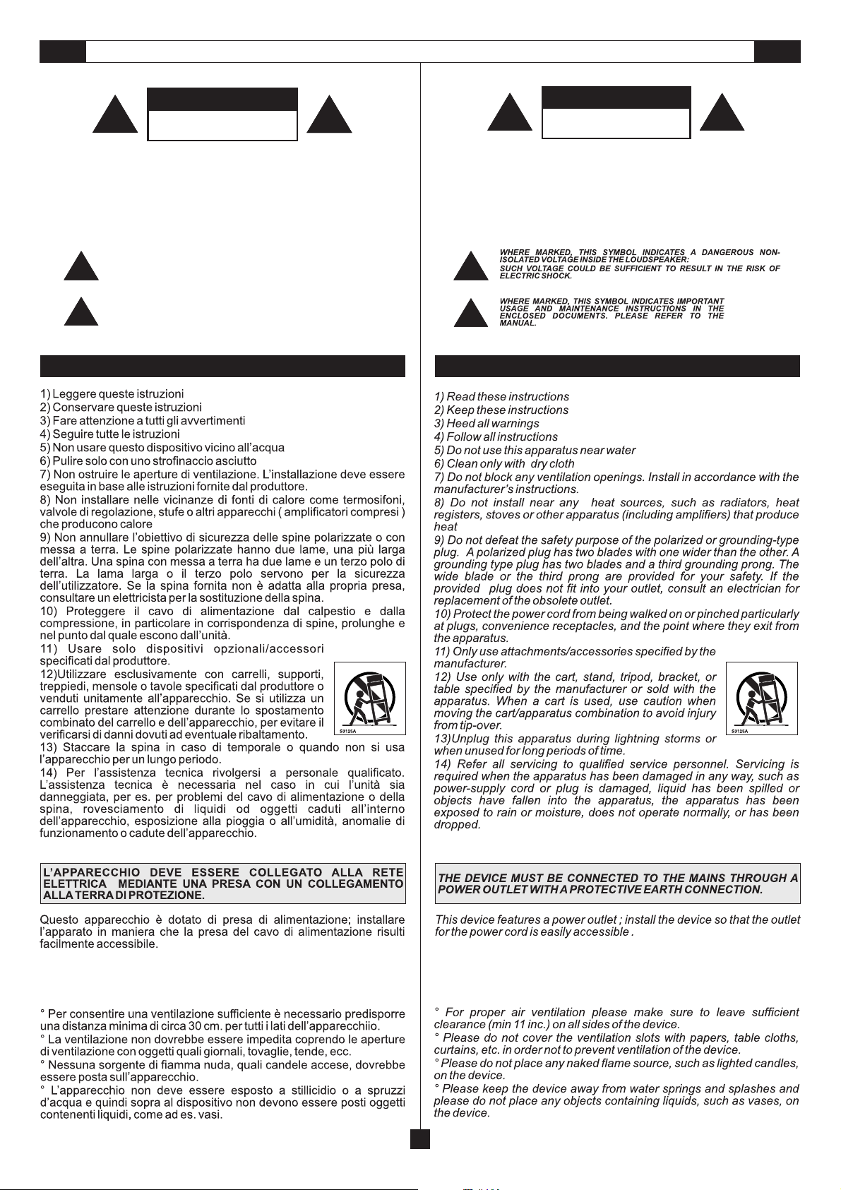
ATTENZIONE - IMPORTANTI ISTRUZIONI DI SICUREZZA - PRECAUZIONI
INTRODUZIONE
CARATTERISTICHE GENERALI
ALIMENTAZIONE
CONNETTORI
DIMENSIONI 9/10
MODALITÀ DI INSTALLAZIONE
CONTROLLI E FUNZIONI
CONNESSIONE DEI DIFFUSORI
CONVERTITORE USB-RS485
ESEMPI DI COLLEGAMENTO
SPECIFICHE TECNICHE
WARNING - IMPORTANT SAFETY INSTRUCTIONS - PRECAUTIONS
INTRODUCTION
GENERAL FEATURES
POWER SUPPLY
CONNECTORS
DIMENSIONS 9/10
INSTALLATION MODE
CONTROLS AND FUNCTIONS
CONNECTION OF LOUDSPEAKERS
USB-RS485 CONVERTER
CONNECTION EXAMPLES
TECHNICAL SPECIFICATIONS
1
3
4/5
6/7
8
11/12/13
14/16
18
19
20
21
1
3
4/5
6/7
8
11/12/13
14/16
18
19
20
21
F
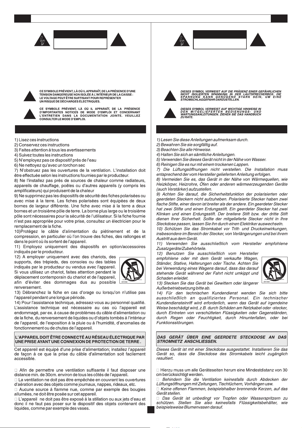
ATTENTION - INFORMATIONS DE SÉCURITÉ IMPORTANTES - PRÉCAUTIONS
INTRODUCTION
CARACTÉRISTIQUES GÉNÉRALES
ALIMENTATION
CONNECTEURS
DIMENSIONS
MODALITÉS D’INSTALLATION
CONTRÔLES ET FONCTIONS
CONNEXION DES DIFFUSEURS
CONVERTISSEUR USB-RS485
EXEMPLES DE CONNEXION
CARACTÉRISTIQUES TECHNIQUES
2
3
4/5
6/7
8
9/10
11/12/13
15/17
18
19
20
21
D
VORSICHT - WICHTIGE SICHERHEITSHINWEISE - VORSICHTSMAßNAHMEN
EINLEITUNG
ALLGEMEINEMERKMALE
VERSORGUNG
ANSCHLÜSSE
ABMESSUNGEN
INSTALLATIONSART
STEUERUNGEN & FUNKTIONEN
ANSCHLUSS DER LAUTSPRECHER
KONVERTER USB-RS485
ANSCHLUSSBEISPIELE
TECHNISCHE DATEN
2
3
4/5
6/7
8
9/10
11/12/13
15/17
18
19
20
21
Page 3
I UK
WARNING
|
|
|
PER EVITARE IL RISCHIO DI SHOCK ELETTRICO
NON USARE UTENSILI MECCANICI ALL'INTERNO
CONTATTARE UN CENTRO DI ASSISTENZA QUALIFICATO
PER EVITARE IL RISCHIO DI INCENDIO O DI SHOCK ELETTRICO
NON ESPORRE L'APPARECCHIATURA ALLA PIOGGIA
QUESTO SIMBOLO AVVERTE, LADDOVE APPARE, LAPRESENZA DI UNA
TENSIONE PERICOLOSA NON ISOLATA ALL’INTERNO DELLA CASSA:
|
|
|
|
IL VOLTAGGIO PU Ò ESS ERE S UFFIC IENTE PER CO STIT UIRE
|
|
IL RISCHIO DI SCOSSA ELETTRICA.
<
<
QUESTO SIMBOLO AVVERTE, LADDOVE APPARE, DELLA
PRESENZA DI IMPORTANTI ISTRUZIONI PER L’USO E PER
LA M ANU TE NZ IO NE N EL LA DOCUMENTAZ IO NE
!
!
ALLEGATA. SI PREGA DI CONSULTARE IL MANUALE.
RISCHIO DI SHOCK ELETTRICO
<
<
NON APRIRE IL COPERCHIO
NON APRIRE
O ALL'UMIDITA'
!
!
ATTENZIONE
ATTENZIONE
|
|
|
|
|
|
|
|
|
<
<
TO REDUCE THE RISK OF ELECTRIC SHOCK
DO NOT REMOVE COVER (OR BACK)
REFER SERVICING TO QUALIFIED SERVICE PERSONNEL
DO NOT EXPOSE THIS EQUIPMENT TO RAIN OR MOISTURE
NO USER SERVICEABLE PARTS INSIDE
TO REDUCE THE RISK OF FIRE OR ELECTRIC SHOCK
|
|
|
|
|
|
<
<
!
!
WARNING
RISK OF ELECTRIC SHOCK
DO NOT OPEN
!
!
IMPORTANTI ISTRUZIONI DI SICUREZZA
IMPORTANTI ISTRUZIONI DI SICUREZZA
IMPORTANT SAFETY INSTRUCTIONS
IMPORTANT SAFETY INSTRUCTIONS
PRECAUZIONI
PRECAUTIONS
1
Page 4
F
D
|
|
|
POUR ÉVITER LE RISQUE DE CHOC ÉLECTRIQUE
NE PAS UTILISER D’OUTILS MÉCANIQUES À L’INTÉRIEUR
CONTACTER UN CENTRE D’ASSISTANCE QUALIFIÉ
POUR ÉVITER LE RISQUE D’INCENDIE OU DE CHOC ÉLECTRIQUE
NE PAS EXPOSER L’APPAREILLAGE À LA PLUIE OU À L’HUMIDIT
|
|
|
<
ATTENTION
RISQUE DE CHOC ÉLECTRIQUE
<
NE PAS OUVRIR LE COUVERCLE
NE PAS OUVRIR
!
!
INFORMATIONS DE SÉCURITÉ IMPORTANTES
|
|
|
<
STROMSCHLAGGEFAHR NICHT DEN DECKEL ÖFFNEN
WENDEN SIE SICH AN EINEN QUALIFIZIERTEN KUNDENDIENST
UM RISIKEN VON STROMSCHLAG UND BRAND AUSZUSCHLIESSEN
SETZEN SIE DAS GERÄT KEINEM REGEN ODER FEUCHTIGKEIT AUS
|
|
|
<
VORSICHT
STROMSCHLAGGEFAHR
NICHT ÖFFNEN
!
!
WICHTIGE SICHERHEITSHINWEISE
PRÉCAUTIONS VORSICHTSMAßNAHMEN
2
Page 5
UKI
3DF4
Page 6
CARATTERISTICHE GENERALI GENERAL FEATURES
CARACTÉRISTIQUES GÉNÉRALES ALLGEMEINE MERKMALE
VERTUS MLA 608A
VERTUS MLA 608A
> Sistema line array attivo a 6 vie (mid/low)
in bass-reflex
> Controllo digitale della direttività
> Pannello di controllo con prese XLR in & link, HP-filter,
volume, presets, 7 diversi angoli di puntamento,
ground-lift, in / out RJ45 per rete RS-485, connettore
Euroblock per ingresso ed uscita audio
> 6 woofer da 200mm al neodimio con bobina da 50mm
> Risposta in frequenza 60Hz - 2kHz
> 6 amplificatori in classe D da 250W (1500W totali) con
3 alimentatori switching
> Direzionalità completamente controllabile attraverso i
comandi posti sul retro del box o per mezzo di un PC
utilizzando l'apposito software dedicato
> Cabinet in alluminio estruso con sistema di aggancio
superiore ed inferiore
> Controllo della direttività full-range da +5° a -25°con
larghezza del fascio sonoro tra 5° e 25°/40°.
> Funzione PC/SLAVE per controllo direttività via PC o
per altri moduli MLA in rete
> Led di stato frontali
> Possibilità di installazione su subwoofer o a muro
tramite accessori in dotazione
VERTUS MLA 608A
> 6-way active mid/low Line Array Column in bass reflex
> Digital directivity aiming
> Control panel with XLR input and XLR link, XLR HP
filtered out, Volume, Preset, 7-step angle aiming, HP
filter, Ground Lift, RJ45 in/out for RS485 network,
screw connectors for in/out audio and for installation
> 6 x 8" custom neodymium woofers with 2" voice coil
> 60Hz - 2kHz frequency response
> 6 Class D 250W RMS amplifiers with three switch
mode power supplies for a total of 1500W power
> Completely controllable directional features through
control switches on the back panel or through PC
software and dedicated RS485 network
> Extruded-aluminum powder-coated cabinet with
superior latching system as well as inferior
> Digital full range aiming from +5° to -25° with included
beamwidth between 5° and 25°/40°
> PC/Slave function for aiming control via PC or other
MLA module in the network
> Frontal status led
> Possibility of mounting on subwoofer or of wall-mount
installation with the supplied bars.
VERTUS MLA 608A
> Système line array actif à 6 voies (mid/low) en bass-
reflex
> Contrôle numérique de la directivité
> Panneau de contrôle avec prises XLR en & link, HP-
filter, volume, pré-réglages, 7 angles de pointage
différents, ground-lift, in / out RJ45 pour réseau RS485, connecteur Euroblock pour entrée et sortie audio
> 6 haut-parleurs de 200 mm au néodyme avec bobine
de 50 mm
> Réponse en fréquence 60Hz - 2kHz
> 6 amplificateurs classe D de 250W (total: 1500W)
avec 3 alimentateurs switching
> Directivité totalement contrôlable à travers les
commandes situées derrière la caisse ou au moyen
d'un PC en utilisant le logiciel prévu à cet effet
> Caisse en aluminium extrudé avec un système
d'accrochage supérieur et inférieur
> Contrôle de la directivité full-range de +5° à -25° avec
largeur du faisceau sonore entre 5° et 25°/40°.
> Fonction PC/SLAVE pour contrôler la directivité via PC
ou pour les autres modules MLA en réseau
> Led état frontaux
> Installation possible sur caisson de grave ou au mur
au moyen des accessoires fournis en dotation
VERTUS MLA 608A
> System line array aktiv mit 6 Wegen (mid/low) in bass-
reflex
> Digitalsteuerung der Richtwirkung
> Steuerpaneel mit Stecker XLR in & link, HP-Filter,
Lautstärke, presets, 7 unterschiedlichen
Ausrichtungswinkeln, ground-lift, in / out RJ45 für Netz
RS-485, Anschluss Euroblock für Eingang und
Ausgang Audio
> 6 woofer mit 200mm mit Neodym und 50mm Spule
> Frequenzgang 60Hz - 2kHz
> 6 Verstärker in Klasse D mit 250W (1500W Total) mit 3
Zuführungsgeräten switching
> Vollständig gesteuerte Richtfähigkeit über die Befehle
auf der Rückseite der Box oder mittels eines PCs mit
der entsprechenden Software.
> Cabinet aus extrudiertem Aluminium mit oberem und
unterem Kopplungssystem
> Steuerung der Richtfähigkeit full-range von +5° bis -
25°mit Breite des Tonbündels zwischen 5° und
25°/40°.
> PC/SLAVE Funktion für Steuerung der Richtfähigkeit
über PC oder für andere MLA Module im Netz
> Led des Frontstatus
> Installationsmöglichkeit auf subwoofer oder an der
Wand mit beigefügten Zubehörteilen
Page 7
CARATTERISTICHE GENERALI GENERAL FEATURES
CARACTÉRISTIQUES GÉNÉRALES ALLGEMEINE MERKMALE
VERTUS MLA 801A
VERTUS MLA 801A
> Sistema line array attivo a 8 vie (HF)
> Algoritmo "proprietario" di controllo della direttività
meccanico / digitale
> Pannello di controllo con prese XLR in & link, volume,
presets, 7 diversi angoli di puntamento, ground-lift, in /
out RJ45 per rete RS-485, connettore Euroblock per
ingresso ed uscita audio
> 8 drivers B&C da 20mm al neodimio con bobina da
25mm
> Risposta in frequenza 1.8kHz - 20kHz
> 8 amplificatori in classe D da 50WRMS (400W totali)
> Direzionalità completamente controllabile attraverso i
comandi posti sul retro del box o per mezzo di un PC
utilizzando l'apposito software dedicato
> Cabinet in alluminio estruso con sistema di aggancio
superiore ed inferiore
> Controllo della direttività combinata digitale/meccanica
da +5° a -25°con larghezza del fascio sonoro tra 5° e
25°/40°.
> 8 motori "passo passo" controllati da microprocessore
> 8 gradi di angolazione in modalità manuale
> Funzione PC/SLAVE per controllo direttività via PC o
per altri moduli MLA in rete
> Led di stato frontali
VERTUS MLA 801A
> 8-way active HF Line Array Column in bass reflex
> Digital / mechanical directivity aiming
> Control panel with XLR input and XLR link, volume,
preset, 7 step angle aiming, ground-lift, RJ45 in /out
for RS-485 network, Euroblock connector for in/out
audio
> 8 x 0,75" B&C neodymium drivers with 1" voice coil
> 1.8kHz - 20kHz frequency response
> 8 Class D 50W RMS amplifiers for a total of 400W
power
> Completely controllable directional features, through
control switches on the back panel or through PC
software and dedicated network
> Extruded-aluminum powder coated cabinet with
superior latching system as well as inferior
> Combined aiming digital / mechanical full-range
system from +5° to -25° with included lobe width
between 5° an 25° / 40°
> 8 hybrid stepped motor controlled by a microprocessor
for the mechanical aiming of wave guides
> PC / Slave function for aiming control via PC or other
MLA module
> Frontal status led
> Possibility of mounting on subwoofer or of wall-mount
installation with the supplied bars.
VERTUS MLA 801A
> Système line array actif à 8 voies (HF) en bass-reflex
> Algorithme "propriétaire" de contrôle de la directivité
mécanique / numérique
> Panneau de contrôle avec prises XLR in & link,
volume, presets, 7 angles de pointage
différents, ground-lift, in / out RJ45 pour réseau RS485, connecteur Euroblock pour entrée et sortie audio
> 8 pilotes B&C de 20mm au néodyme avec bobine de
25mm
> Réponse en fréquence 1.8kHz - 20kHz
> 8 amplificateurs Classe D de 50WRMS (400W total)
> Directivité totalement contrôlable à travers les
commandes situées derrière la caisse ou au moyen
d'un PC en utilisant le logiciel prévu à cet effet
> Caisse en aluminium extrudé avec un système
d'accrochage supérieur et inférieur
> Contrôle de la directivité combinée mécanique /
numérique de +5° à -25°avec largeur du faisceau
sonore entre 5° et 25°/40°.
> 8 moteurs "pas à pas" contrôles par un
microprocesseur
> Fonction PC/SLAVE pour contrôler la directivité via PC
ou pour les autres modules MLA en réseau
> Led état frontaux
> Installation possible sur caisson de grave ou au mur
au moyen des accessoires fournis en dotation
VERTUS MLA 801A
> System line array aktiv mit 8 Wegen (HF)
> Digitalsteuerung der Richtwirkung
> Steuerpaneel mit Stecker XLR in & link, volume,
presets, 7 unterschiedlichen Ausrichtungswinkeln,
ground-lift, in / out RJ45 für Netz RS-485, Anschluss
Euroblock für Eingang und Ausgang Audio
> 8 drivers B&C mit 20mm mit neodym und 25mm
Spule
> Frequenzgang 1.8kHz - 20kHz
> 8 Verstärker in Klasse D mit 50WRMS (400W totali)
> Vollständig gesteuerte Richtfähigkeit über die Befehle
auf der Rückseite der Box oder mittels eines PCs mit
der entsprechenden Software.
> Cabinet aus extrudiertem Aluminium mit oberem und
unterem Kopplungssystem
> Steuerung der kombinierten digitalen / mechanischen
Richtfähigkeit von da +5° bis - 25° mit Tonbündelbreite
zwischen 5° und 25° / 40°
> 8 durch Mikroprozessoren gesteuerte " Schritt für
Schritt " Motoren
> PC/SLAVE Funktion für Steuerung der Richtfähigkeit
über PC oder für andere MLA Module im Netz
> Led des Frontstatus
> Installationsmöglichkeit auf subwoofer oder an der
Wand mit beigefügten Zubehörteilen
5
Page 8
ALIMENTAZIONE
220 - 230V
POWER SUPPLY
UKI
Per l’alimentazione elettrica la serie MLA è fornita di due prese NEUTRIK
«powercon» a 3 poli con connettori a bloccaggio. Utilizzare la presa di
colore grigio per collegare più diffusori insieme; quella blu per fornire
l’alimentazione al sistema tramiteilconnettorefornito in dotazione.
ATTENZIONE:
il cavo in dotazione può essere utilizzato solo e solo nel
caso in cui l’assorbimento di corrente complessivo è inferiore a 16A (vedi
esempio 1).
ATTENZIONE:
non sostituire la spina in dotazione del cavo di
alimentazione con un’altra spina, in quanto il cavo di alimentazione è in
grado di supportare unacorrentemassimadi 16A(vedi esempio 1)
ATTENZIONE:
se la corrente assorbita è maggiore di 16Ae minore di 20A
va realizzato (da personale specializzato) un collegamento di
alimentazione utilizzando un cavo H05VV-F con sezioneda 2.5mmq. e una
spina con corrente nominale >=20A, dove 20A è la massima corrente
nominale del connettore Powercon(vediesempio2).
L’assemblaggio del cavo di rete deve essere effettuato da personale
specializzato seguendo le regoleimpiantistichenazionali.
- Proteggere il cavodiretequando non è utilizzato
- Per un collegamento a «catena» collegare il cavo della presa di colore
grigio del primo diffusore alla presa blu del secondo, e così via,
facendo
attenzione a non superare la corrente massima dichiarata sulla presa
«AC LOOP OUTPUT».
ALIMENTATION
MLA MLA
For its power supply, the whole MLA series features two NEUTRIK
powercon three-pole outletswith locking connectors. Use thegrey outlet for
connecting several speakers with one another, and the blue one for
supplying power to thesystemthrough the connector supplied.
CAUTION:
the cable supplied can be used alone, and only if the total
current absorption is lowerthan16A(seeexample 1)
CAUTION:
never replace the plug of the power cord supplied since the
power cord can onlysupporta maximum current of 16A (see example1)
CAUTION:
if the absorbed current exceeds 16A and is lower than 20A, a
power cord has to be manufactured by specialized staff using a H05VV-F
cable with 2.5sq.mm section and plugwith rated current>=20A, where 20A
is the maximum ratedcurrentofthe powercon connector (see example2).
- The power cord has to be assembled by specialized staff complying with
national plant-engineering regulations
- Protect the mainscablewhen it is not used
- In case of «chain connection», connect the cable to the grey outlet of the
first speaker and to the blue outlet of the second one, and so on,
making
sure the maximum current indicated on the «AC LOOP OUTPUT» is
not exceeded.
VERSORGUNG
DF
MAX. 16A
1
MAX. 20A
SPINA INDUSTRIALE
INDUSTRIAL PLUG
FICHE INDUSTRIELLE
INDUSTRIESTECKER
> / = 20A
2
12A
CAVO IN DOTAZIONE
SUPPLIED CABLE
CÂBLE EN DOTATION
MITGELIEFERTES KABEL
18A 6A
CAVO / H05VV-FCABLE / KABEL
SEZIONE / 2.5mmSECTION
6A
MAX. 2 BOX
6A 15A
MLA 608A MLA 608A
6A
MLA 608A MLA 608A
MAX. 3 BOX
6
1.5A
MLA 801A MLA 801A
19.5A 1.5A
MLA 801A MLA 801A
1.5A
MAX. 10 BOX
1.5A
MAX. 13 BOX
Page 9

ALIMENTAZIONE
120V
POWER SUPPLY
UKI
Per l’alimentazione elettrica tutta la serie MLA è fornita di due prese
NEUTRIK “powercon” a 3 poli con connettori a bloccaggio. Utilizzare la
presa di colore grigio per collegare più diffusori insieme, quella blu per
fornire l’alimentazione al sistema mediante il connettore fornito in
dotazione.
ATTENZIONE:
Se la richiesta complessiva di corrente è inferiore a 12A
utilizzare il cavo dialimentazioneindotazione (vedi fig.1).
Se la richiestacomplessiva di corrente èsuperiorea 12A ed inferiore a18A,
utilizzare un cavo di alimentazione AWG14 SJT VW1 con una spina di
corrente nominale superiore ougualea24A(vedifig. 2).
In entrambi i casi non superare le correnti massime riportate nelle
MAI
figure 1 e 2.
ILCAVO E LA SPINADEVONOESSERE CERTIFICATI O .
UL CSA
- L’assemblaggio del cavo di rete deve essere effettuato da personale
specializzato seguendo le regoleimpiantistichenazionali.
- Proteggere ilcavo di rete quando nonèutilizzato.
- Per un collegamento “a catena” collegare il cavo dalla presa di colore
grigio del primo diffusore alla presa blu del secondo, e così via, facendo
attenzione a non superare la corrente massima dichiarata sulla
presa “AC LOOP OUTPUT”.
ALIMENTATION
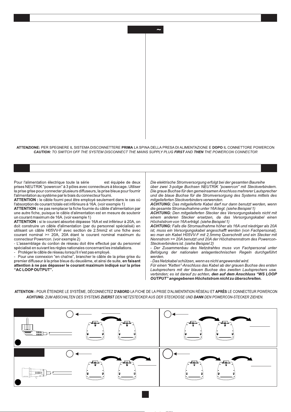
Pour l'alimentation électrique toute la sérieMLAest équipée dedeux prises
Neutrik powercon à 3 pôles avec connecteurs à blocage. Utiliser la prise
grise pour connecter plusieurs diffuseurs, la prise bleu pour fournir
l'alimentation au système parlabiaisdu connecteur fourni.
ATTENTION:
le câble d'alimentation fourni(voirfig.1).
Si le demandetotale de courant dépasse12Amais elle est inférieure à18A,
utiliser un câble d'alimentationAWG14SJT VW1avec unefiche aucourant
nominal supérieur ou égalà24A(voir fig.2).
Dans les deux cas, ne dépasser les courants maximum indiqués
dans les figures 1et2.
LE CÂBLE ET LA FICHE DOIVENT ÊTRE CERTIFIÉS OU .
- L'assemblage du cordon de réseau doit être effectué par du personnel
spécialisé en suivant lesrèglesnationalesconcernant les installations.
- Protéger lecâble de réseau lorsqu'il n'estpasemployé.
- Pour une connexion "en chaîne", brancher le câble de la prise grise du
premier diffuseur àla prise bleu du deuxième, et ainsi desuite, en faisant
attention à nepas dépasser lecourant maximum indiquésur la prise
"AC LOOP OUTPUT".
Si lademande totale decourant ne dépasse pas 12A,utiliser
JAMAIS
UL CSA
For its power supply the whole MLA series features two NEUTRIK
powercon three-pole outletswith locking connectors. Usethe grey outlet for
connecting several speakers with one another, and the blue one for
supplying power to thesystemthrough the connector supplied.
CAUTION:
If thetotal current demanddoes not exceed 12A, use the power
cable supplied (see pict.1).
If the total current demand is between 12A and 18A, use the power cable
AWG14 SJT VW1 with plugratedcurrent equal to 24A or lower (seepict.2).
In both cases exceed the maximumcurrentvalues shown in picture
NEVER
1 and 2.
THE CABLE AND THE PLUG MUST HOLD THE OR
UL CSA
CERTIFICATION.
- The power cord has to be assembled by specialized staff complying with
national plant-engineering regulations.
- Protect themains cable when it isnotused.
- In case of "chain connection" connect the cable to the grey outlet of the
first speaker and to the blue outlet of the second one, and so on, making
sure the maximumcurrentindicated on the "AC LOOPOUTPUTS" is
not exceed.
VERSORGUNG
DF
Die elektrische Stromversorgung erfolgt bei der gesamten Baureihe MLA
über zwei 3-polige Buchsen Neutrik powercon mit Steckverbindern. Die
graue Buchse für den gemeinsamen Anschluss mehrerer Lautsprecher
und die blaue Buchse für die Stromversorgung des Systems mittels des
mitgelieferten Steckverbinders verwend en.
ACHTUNG:
Ist die gesamte Stromanfrage unter 12A, bitte das
mitgelieferte Versorgungskabel verwenden (siehe Abb. 1).
Ist die gesamte Stromanfrage über 12A aber unter 18A, ein
VersorgungskabelAWG14SJTVW1 mit einem SteckerfürNennstrom über
oder gleich 24A verwenden (siehe Abb. 2).
In beiden Fällen die maximalen Ströme übersteigen, die in den
NIEMALS
Abbildungen 1 und 2angegebensind.
DAS KABEL UND DER STECKER MÜSSEN - ODER
UL CSA
ZERTIFIZIERTSEIN.
- Der Zusammenbau des Netzdrahtes muss von Fachpersonal unter
Befolgung der nationalen anlagentechnischen Regeln durchgeführt
werden.
- Das Netzkabelschützen, wenn es nicht angewendetwird.
- Für einen "ketten"-Anschluss das Kabelab der grauen Buchsedes ersten
Lautsprechers mit der blauen Buchse des zweiten Lautsprechers usw.
verbinden; es ist darauf zu achten,
den auf dem Anschluss " AC LOOP
OUTPUT " angegebenen Höchststromnichtzuüberschreiten.
MAX. 12A
NEMA 5-15P
1
MAX. 18A
2
12A 12A
SJT3X14 VW1
CAVO IN DOTAZIONE
SUPPLIED CABLE
CÂBLE EN DOTATION
MITGELIEFERTES KABEL
Corrente nominale della spina >= 24A
Plug rated current >= 24A
Courant nominal de la fiche >= 24A
Nennstrom des Steckers >= 24A
AWG14 SJT VW1
NB. il disegno della spina della figura è indicativo
NOTE. plug drawing is for indication only
NOTA. l'image de la fiche montrée dans la figure n'est qu'indicative
ANM. Die Zeichnung des Steckers ist nicht detailgetreu
MAX. 5 mt. / 16.4 ft.
MLA 608A
12A 12A
MLA 608A
1 BOX
12A
3A
3A
MAX. 4 BOX
MLA 801A MLA 801A
1 BOX
18A
3A
3A
MAX. 6 BOX
MLA 801A MLA 801A
7
Page 10

8
Page 11

DIMENSIONI
DIMENSIONS
DIMENSIONS
ABMESSUNGEN
MLA 608A
9
Page 12

DIMENSIONI
DIMENSIONS
DIMENSIONS
ABMESSUNGEN
MLA 801A
10
Page 13

MODALITÀ DI INSTALLAZIONE
INSTALLATION MODE
MODALITÉS D’INSTALLATION
I diffusori della serie vanno installati tramite sospensione
mediante staffe a muro.
Tutti i diffusori appesi in teatri, palasport o altri luoghi di lavoro e/o
intrattenimento, oltre al sistema di sospensione principale, devono essere
provvisti di un sistema di sicurezzasecondario indipendentee dicapacità di
carico adeguata.
Les diffuseurs de la série doivent être suspendus au moyen
d'étriers muraux.
En plus du système de suspension principal, tous les diffuseurs suspendus
dans desthéâtres, des palais des sportsou dans d'autres endroits detravail
et/ou de divertissement doivent être équipés d'un système de sécurité
secondaire indépendant et ayantunecapacitéde charge adéquate.
ATTENZIONE: Selezionare con cura l’area dove installare i diffusori e
assicurarsi che la strutturasiaadeguataa supportare il peso deibox.
La FBTnon èresponsabile di eventuali danni a persone o cose in caso
di mancato rispetto delle presenti indicazioni o mancata verifica del
fattore di sicurezza di tutti gli elementi coinvolti nella sospensione del
sistema.
ATTENTION: choisir soigneusement l’endroit où installer les hautparleurs et s’assurer que la structure est suffisante pour supporter le
poids des boîtes.FBT n’est pasresponsable des dommages éventuels
aux personnes ou choses en casde manquede respectdes présentes
indications ou non vérification du facteur de sécurité sur tous les
éléments impliqués dans lasuspensiondusystème.
VERTUS MLA
VERTUS MLA Die Verteiler der Serie werden mittels Wandbügel
INSTALLATIONSART
!!
The loudspeakers of the series must be installed by
suspension using wall brackets.
Besides the main suspension system, all flying speakers in theatres, indoor
stadiums or in several other work and/or leisure facilities shall be provided
with an additional independent safety system with the adequate load
capacity.
aufgehängt.
Alle Lautsprecher, die in Theater, Sporthallen oder weiteren Arbeits-und
Vergnügungsorten aufgehangen sind, müssen außer mit dem
Haupt hänge sy ste m a uch mit ein em zwe it en u na bhä ng igen
Sicherheitssystem mit angemessener Tragfähigkeitausgestattet sein.
WARNING: carefully select the area where to install the speakers and
make sure that the structure is adequate to support the weight of
boxes. FBT will not be held responsible for any damage to persons or
property in case of failure to comply with these instructions or failure
to check the safety factor of all components involved in the installation
system.
ACHTUNG: Den Bereich, wo die Lautsprecher zu installieren sind,
sorgfältig auswählenum undsicherstellen, dass die Struktur geeignet
ist, um dasGewicht der Boxzu stützen. FBT istnicht verantwortlich für
Schäden an Personenoder Sachen imFalle der Nichtbeachtung dieser
Anweisungen oder der nicht erfolgten Prüfung des Sicherheitsfactors
aller an der Aufhängung des SystemsbeteiligtenBestandteile.
VERTUS MLA
VERTUS MLA
11
Page 14

MODALITÀ DI INSTALLAZIONE
INSTALLATION MODE
MODALITÉS D’INSTALLATION
AGGANCIO DI DUE COLONNE / / ACCROCHAGE DES DEUX COLONNES /CONNECTION OF TWO COLUMNS KOPPLUNG ZWEIER SÄULEN
INSTALLATIONSART
1
2
fig. A
- Agganciare iduesatelliti tra loro come illustratonellafigura"A".
- Per la sospensione del sistema a parete utilizzare le apposite asole di
ancoraggio.
ANCHOR SLOTS
FENTES DE FIXATION
VERANKERUNGSÖSEN
ASOLE DI ANCORAGGIO
- Connect the twosatellitestoone another as shown inpicture"A".
- For wall mountinguseadequateanchor slots.
- Accrocher lesdeuxsatellites entre eux tel qu'illustrerdanslafig. "A".
- Pour lasuspensiondu système au mur utiliserlesfentesde fixation.
- Die zwei SatellitenuntereinanderwieinAbb."A".
- Für die Aufhängung des Systems an der Wand, die entsprechenden
Verankerungsösenverwenden.
12
Page 15

MODALITÀ DI INSTALLAZIONE
INSTALLATION MODE
MODALITÉS D’INSTALLATION
AGGANCIO DI DUE COLONNE / / ACCROCHAGE DES DEUX COLONNES /CONNECTION OF TWO COLUMNS KOPPLUNG ZWEIER SÄULEN
STAFFA SUPERIORE
UPPER BRACKET
ÉTRIER SUPÉRIEUR
OBERER BÜGEL
INSTALLATIONSART
STAFFA INFERIORE
LOWER BRACKET
ÉTRIER INFÉRIEUR
UNTERER BÜGEL
Per il fissaggio a parete delle due colonne utilizzare la staffa superiore e
quella inferiore. Le staffe centralivanno toltee una delle due utilizzata come
aggancio di sicurezza (vedifig.B).
ATTENZIONE
assolutamente chiusi con leappositeviti.
Pour la fixation murale des deux colonnes utiliser l'étrier supérieur et celui
inférieur. Les étriers centraux doivent être enlevés et un des deux doit être
utilisé comme crochet desécurité(voir fig. B ).
ATTENTION
doivent être absolument bouchésaveclesvis appropriées.
: i fori (C) lasciati liberi dallo spostamento della staffa vanno
: les trous ( C ), laissés libres par le déplacement de l'étrier,
fig. B
To fasten the two columns onto the wall use the upper and lower brackets.
The central brackets must be removed and one of them used as safety
fastening (see fig. B).
CAUTION
closed with the relevantscrews.
Für die Wandbefestigung der zwei Säulen den oberen und den unteren
Bügel verwenden. Die zentralen Bügel müssen entfernt werden. Einen
dieser Bügel als Sicherheitshakenverwenden( sieheAbb. B ).
ACHTUNG
müssen in jedem Fall mit den entsprechenden Schrauben verschlossen
werden.
13
: holes ( C ) let loose by the moving bracket must absolutely be
: die durch das Verschieben freigelassenen Bohrungen ( C )
Page 16

CONTROLLI E FUNZIONI
CONTROLS AND FUNCTIONS
ON:
Indica l’accensione del sistema.
PEAK/LIMIT:
L’accensione del led "peak" indica che il
livello del segnale è prossimo alla saturazione; il
led "limit"
indica l’intervento dei circuiti di limitazione per
evitare sovraccarico termico.
TILT NO ALLOWED:
indica un errore di
"puntamento"; controllare nella tabella "allowed
angle settings" i limiti massimi di inclinazione del
fascio sonoro.
NETWORK ON:
segnala l'attivazione della
connessione alla rete.
TILT ANGLE:
permette di selezionare l'angolo di
inclinazione del fascio sonoro. Per convenzione
gli angoli negativi si riferiscono ad una
inclinazione del fascio sonoro verso la parte
bassa della cassa; i limiti massimi di inclinazione
del fascio sonoro, associati all'angolo di
copertura, sono indicati nell'apposita tabella.Nel
caso si eccedano tali valori verrà segnalato un
errore di puntamento tramite il led "TILT NO
ALLOWED". La posizione PC/ SLAVE pone il
diffusore in modalità ricezione dati con la
possibilità dicontrollarla tramite laseconda cassa
ad esso connessao tramite l'appositosoftware su
PC.
BEAMWIDTH:
permette di selezionarel'angolodi
apertura del fascio sonoro; seguire i limiti riportati
nella tabella per una impostazione corretta del
sistema.
VOLUME:
PRESET:
Regola il volume delsingolodiffusore.
Seleziona 4 preset ad ognuno dei quali
corrisponde una diversa equalizzazione in base
al l'installazio ne da ese gu ire (F OH per
installazioni in campo aperto o WALL per
installazioni fisse) edell'utilizzo ( FLATpermusica
o VOCAL per il parlato ).
RESET:
permette di effettuare un reset della
memoria interna contenente idati inviati dal PC in
un eventuale precedente setup. Se effettuato in
modalità "stand alone" con casse collegate, il
comando di reset viene trasmesso anche al
diffusore MLA 608A. Si consiglia di effettuare il
reset ( tramite apposito tasto o tramite software)
nel momento in cui si passa dall'utilizzo del
sistema collegato a PC ad un impiego "stand
alon e ", c o sì da e l imin a re ogn i d ato
precedentemente inviato alle casse ed eliminare
così la possibilità dimalfunzionamenti.
GND LIFT:
interruttore per la separazione
elettrica tra il circuito di massa e il circuito di terra
onde evitare possibili "loop" di massa, causa di
fastidiosi ronzii.
IN - LINK:
Prese di ingresso/uscita bilanciate;
«IN» consente il collegamento di un segnale
preamplificato come, ad esempio, quello in uscita
da un mixer. «LINK» permette il collegamento di
più diffusori con lo stesso segnale.
UTILIZZARE LE
PRESE "EUROBLOCK" PER IL COLLEGAMENTO A
PARETE.
IN-NETWORK-OUT:
vedi descrizione nella sezione
"CONNESSIONE DEI DIFFUSORI".
VERTUS
MLA 801A
NETWORK ON
ON PEAK
TILT NOALLOWED
LIMIT.
25°
20°
-10°-15°
-20°
30°
15°
-5°
35°
-25°
10°
0°
5°
5°
40°
PC
slave
TILTANGLE
BEAMWIDTH
LINK
2
0
dB
134
VOLUME
PRESET
IN
ON
RESET GND LIFT
IN-NETWORK-OUT LINK IN
LINK IN
AllowedAngle Settings
TiltAngle
5° 0° -5° -10° -15° -20° -25°
from
5° 5° 5° 5° 5° 10° 25°
Beamwidth
to
40° 40° 40° 40° 40° 40° 25°
Preset Chart
3 - FOH FLAT
1 - WALLFLAT
2 - WALLVOCAL
4 - FOH VOCAL
801A
MLA
VERTUS
AC LOOPOUT
AC FUSE
T 2.5A
250 V
220 - 230V
50 60 Hz/
14Amax.
CAUTION
RISK OF ELECTRIC SHOCK
DO NOT OPEN
MADE IN ITALY
AC INPUT
220 - 230V
50 60 Hz/
6Amax.
ON:
Indicates that the systemison.
PEAK/LIMIT:
When the “peak” LED goes on, it indicates
that the signal level is nearing saturation; the
“limit” LED indicates that the temperature limiting
circuits have triggered toprevent the system from
overheating.
TILT NOT ALLOWED:
indicates a “pointing”
error; check the maximumallowedtilt of the sound
band in the “allowedanglesettings” table.
NETWORK ON:
signals that connection to the
network has been enabled.
TILTANGLE:
allows youto set thetilt angle of the
sound beam. Negative angles conventionally
refer to a sound beam tilted toward the lower part
of the speaker; the maximum tilt limits of the
sound beam associated to the covering angle are
shown in the relevant table. If these values are
exceeded, a pointing error will be signaled by the
“TILT NOT ALLOWED” LED going on. The
PC/SLAVE position brings the loudspeaker in
data receivingmode, with the option ofcontrolling
it viathe second speakerconnected to it or via the
relevant software on thePC.
BEAMWIDTH:
allows you to select the opening
angle of the sound beam; follow the limitslisted in
the table to properlyprogramthe system.
VOLUME:
Adjusts the volume of the single
loudspeaker.
PRESET:
Selects 4 presets, each corresponding
to a different equalization, based on the
installation to be performed (FOH for installations
in open field or WALL for fixed installations) and
the use made of the system (FLAT for music or
VOCAL for speech).
RESET:
allows you to reset the internal memory
that contains the data sent by the PC in a setup
possibly configured previously. If performed in
“stand-alone” mode withconnected speakers, the
reset control is also transmitted to the MLA 608A
loudspeaker. We recommend that you perform a
reset (pressing the relevant key or with the
software) when shifting from using the system
connected tothe PC to“stand-alone” mode, so as
to eliminate the possibilityofany malfunctions.
GND LIFT:
electrical switch for the electrical
separation between the massandground circuits,
in order to avoid possible mass“loops”, which are
the source of bothersomehummingsound.
IN - LINK:
Balanced input/output sockets; “IN”
allows the connection of pre-amplified signal,
such as for instance the one in output from a
mixer. “LINK” allows you to connect multiple
loudspeakers t o the same signal.
“E UROBLOCK” SOCKETS FOR WALL
CONNECTIONS.
IN-NETWORK-OUT:
see the description in the
"CONNECTION OF LOUDSPEAKERS" section.
USE
14
Page 17

CONTRÔLES ET FONCTIONS
STEUERUNGEN UND FUNKTIONEN
ON:
Indique la mise enmarchedusystème.
PEAK/LIMIT:
L'éclairage de la led "peak" indique que le
niveau du signal est proche de la saturation;la led
"limit" indique l'intervention des circuits de
limitation pour éviter lasurchargethermique.
TILT NO ALLOWED:
indique une erreur de
"pointage"; contrôler dans le tableau "allowed
angle settings" leslimites maximales d'inclinaison
du faisceau sonore.
NETWORK ON:
signale l'activation de la
connexion au réseau.
TILT ANGLE:
permet de sélectionner l'angle
d' in cl in ai so n d u f ai sc ea u s onore. Pour
convention, les angles négatifs se réfèrent à une
inclinaison du faisceau sonore vers la partie
basse de l'enceinte, les limites maximales
d'inclinaison du faisceau sonore (associées à
l'angle de couverture) sont indiquées dans le
tableau. Une erreur de pointage sera signalée (au
moyen de la led "TILT NO ALLOWED") si ces
valeurs sont dépassées. La position PC/ SLAVE
met le diffuseur en mode de réception des
données avec la possibilité de le contrôler au
moyen de ladeuxième enceinte branchéedessus
ou au moyen dulogicielappropriésur PC.
BEAMWIDTH:
permet de sélectionner l'angle
d'ouverture du faisceau sonore; suivre les limites
indiquées dans le tableau pour configurer
correctement le système.
VOLUME:
Permet de régler le volume d'un seul
diffuseur.
PRESET:
Permet de sélectionner 4 pré-réglages
do nt chacun des qu el s c or respond un e
égalisation différente enfonction de l'installation à
effectuer (FOH pourles installations aériennesou
WALLpour les installations fixes) etde l'utilisation
(FLATpour lamusique ou VOCAL pour la voix).
permet d'effectuer une réinitialisation de
RESET:
la mémoire interne contenant les données
envoyées par le PC lors d'un éventuel réglage
précédent. S'il est effectué en mode"stand alone"
avec les enceintes branchées, la commande de
réinitialisation est également transmise au
diffuseur MLA608A. Nous conseillons d'effectuer
la réinitialisation (au moyende la touche prévue à
cet effet ou du logiciel) après être passé de
l'utilisation du système branché au PC à une
utilisation "stand alone", de façon à éliminer
chaque donnée envoyée précédemment aux
enceintes et éliminer ainsi la probabilité de
dysfonctionnements.
GND LIFT:
interrupteur pour la séparation
électrique entre le circuit de masse et le circuit de
terre afin d'éviter des éventuelles "loop" de
masse, causes de perturbations.
IN - LINK:
Prises d'entrée/sortie balancées; «IN»
permet de connecter un signal préamplifié
comme, par exemple, celui en sortie d'un mixeur. «LINK»
permet de connecter plusieurs diffuseurs au même
signal.
UTILISER LES PRISES "EUROBLOCK" POUR
LACONNEXION MURALE.
IN-NETWORK-OUT:
voir la description dans la section
"CONNEXION DES DIFFUSEURS".
VERTUS
MLA 801A
NETWORK ON
ON PEAK
TILT NOALLOWED
LIMIT.
25°
20°
-10°-15°
-20°
30°
15°
-5°
35°
-25°
10°
0°
5°
5°
40°
PC
slave
TILTANGLE
BEAMWIDTH
LINK
2
0
dB
134
VOLUME
PRESET
IN
ON
RESET GND LIFT
IN-NETWORK-OUT LINK IN
LINK IN
AllowedAngle Settings
TiltAngle
5° 0° -5° -10° -15° -20° -25°
from
5° 5° 5° 5° 5° 10° 25°
Beamwidth
to
40° 40° 40° 40° 40° 40° 25°
Preset Chart
3 - FOH FLAT
1 - WALLFLAT
2 - WALLVOCAL
4 - FOH VOCAL
801A
MLA
VERTUS
AC LOOPOUT
AC FUSE
T 2.5A
250 V
220 - 230V
50 60 Hz/
14Amax.
CAUTION
RISK OF ELECTRIC SHOCK
DO NOT OPEN
MADE IN ITALY
AC INPUT
220 - 230V
50 60 Hz/
6Amax.
ON:
System ist in Betrieb.
PEAK/LIMIT:
Das Aufleuchten des Led "peak" zeigt an,
dass das Niveau der Anzeige bald gesättigt ist;
mit dem Led "limit" wird die Aktivierung der
Begrenzungskreisläufe zur Verhinderung der
Überhitzung angezeigt.
TILT NO ALLOWED:
zeigt einen Fehler der
“Ausrichtung” an; in der Tabelle "allowed angle
settings" die Maximallimits der Neigung des
Tonbündels prüfen.
NETWORK ON:
zeigt die Aktivierung des
Netzanschlusses an.
TILT ANGLE:
ermöglicht den Neigungswinkel
des Tonbündels zu wählen. Gemäß Konvention
entsprechen die negativen Winkel einer Neigung
des Tonbündels in dem unterem Boxenteil; die
Maximallimits der Neigung des Tonbündels,
zusammen mit dem Deckungswinkel werden in
der entsprechenden Tabelle angegeben. Sollten
diese Werte überschritten werden, wird über das
Led “TILT NOALLOWED” einAusrichtungsfehler
angezeigt. Die Position PC/ SLAVE stellt den
Lautsprecher in Modalität Datenempfang mit der
Möglichkeit diese über die angeschlossene
zweite Box oder über die entsprechende
Software auf dem PCzusteuern.
BEAMWIDTH:
ermöglicht den Öffnungswinkel
des Tonbündels zu wählen; die in der Tabelle für
ei ne korrek te Einste ll un g des Sy st ems
aufgeführten Limits beachten.
LAUTSTÄRKE:
Reguliert die Lautstärke jedes
einzelnen Lautsprechers.
PRESET:
Wählt 4 Preset. Jedem Preset
entspricht eine unterschiedliche Entzerrung
entsprechend der auszuführenden Einstellung
(FOH für Einstellungen im geöffneten Feld oder
WALL für fixe Einstellungen) und des Einsatzes
(FLATfürMusikoder VOCAL für Gesprochenes).
R E S ET:
e r m ögli c h t ein R e set d e s
Innenspeichers, der Datenenthält, die vomPC zu
einem eventuellen vorausgehenden Setup
gesendet wurden. Wird das in Modalität „stand
alone“ mit verbundenenBoxen durchgeführt, wird
der Reset-Befehl auch auf den Lautsprecher
MLA608A übertragen. Es wird empfohlen das
Reset (mittels entsprechender Taste oder mittels
Software) in dem Moment auszuführen, wenn
man vom System, das an den PC angeschlossen
ist, auf einen Einsatz „stand alone“ wechselt. So
wird jede zuvor den Boxen zusandte Angabe
entfernt und Betriebsstörungen vermieden.
GND LIFT:
Schalter für die Stromtrennung
zwischen Einzelleiterstromkreis und geerdeter
Stromkreis, damit mögliche“loop” der Erdung, die
störende Brummge räusche ve rursachen ,
vermieden werden.
IN - LI NK:
Symm e tri s che E i nga n gsAusgangsstecker; «IN» ermöglicht den Anschluss eines
vorverstärkten Signals wie zum Beispiel das des
Ausgangs eines Mixers. «LINK» ermöglicht den
Anschluss mehrere Lautsprecher mit dem gleichen
Si gnal.
„E UROBLOC K“ -STECKER F ÜR DEN
WANDANSCHLUSSVERWENDEN.
IN-NETWORK-OUT:
siehe Beschreibung im Abschnitt
"ANSCHLUSS DER LAUTSPRECHER".
15
Page 18

CONTROLLI E FUNZIONI
CONTROLS AND FUNCTIONS
ON:
Indica l’accensione del sistema.
PEAK/LIMIT:
L’accensione del led "peak" indica che il
livello del segnale èprossimoallasaturazione; il led "limit"
indica l’intervento dei circuiti di limitazione per evitare
sovraccarico termico.
TILT NO ALLOWED:
indica un errore di "puntamento";
controllare nella tabella "allowed angle settings" i limiti
massimi di inclinazione delfasciosonoro.
NETWORK ON:
segnala l'attivazione della connessione
alla rete.
TILT ANGLE:
permette di selezionare l'angolo di
inclinazione del fascio sonoro.Per convenzione gli angoli
negativi si riferiscono ad una inclinazione del fascio
sonoro verso la parte bassa della cassa; i limiti massimi di
inclinazione del fascio sonoro, associati all'angolo di
copertura, sono indicati nell'apposita tabella.Nel caso si
eccedano tali valori verrà segnalato un errore di
puntamento tramite il led "TILT NO ALLOWED". La
posizione PC/ SLAVE pone il diffusore in modalità
ricezione dati con la possibilità di controllarla tramite la
seconda cassa ad esso connessa o tramite l'apposito
software su PC.
BEAMWIDTH:
permette di selezionare l'angolo di
apertura del fascio sonoro; seguire i limiti riportati nella
tabella per una impostazionecorrettadelsistema.
VOLUME:
PRESET:
Regola il volume delsingolodiffusore.
Seleziona 4 preset ad ognuno dei quali
corrisponde una diversa equalizzazione in base
all'installazione da eseguire (FOH per installazioni in
campo aperto oWALL per installazioni fisse)edell'utilizzo
( FLATpermusicao VOCALper il parlato ).
GND LIFT:
interruttore per la separazione elettrica tra il
circuito di massa e il circuito di terra onde evitare possibili
"loop" di massa, causadifastidiosironzii.
HP FILTER:
la selezione di questo controllo modifica il
filtro "hi-pass" a circa 100Hz permettendo così l'utilizzo in
abbinamento di un subwoofer della serie FBT SUBLINE;
in questo caso, per ottenere un corretto allineamento dei
ritardi deisegnali del diffusoreMLAe del sub,si consiglia
l'utilizzo dell'apposita uscita disegnale"SUBOUT".
IN - LINK -SUBOUT :
Prese di ingresso/uscita bilanciate;
«IN» consente il collegamento di un segnale
preamplificato come, ad esempio, quello in uscita da un
mixer; «LINK» permette il collegamento di più diffusori
con lo stesso segnale; "SUB OUT" per collegare un
subwoofer.
UTILIZZARE LE PRESE "EUROBLOCK"
PER IL COLLEGAMENTOAPARETE.
IN-NETWORK-OUT:
vedi descrizione nella sezione
"CONNESSIONE DEI DIFFUSORI".
VERTUS
MLA 608A
TILT NOALLOWED
NETWORK ON
ON PEAK
LIMIT.
SUB OUT
25°
20°
-10°-15°
-20°
30°
15°
-5°
35°
-25°
10°
0°
5°
5°
40°
PC
slave
TILTANGLE
BEAMWIDTH
LINK
2
0
dB
134
VOLUME
PRESET
IN
ON
OFF ON
HPFILTER GND LIFT
IN-NETWORK-OUT SUB OUT LINK IN
SUB OUT LINK IN
AllowedAngle Settings
TiltAngle
5° 0° -5° -10° -15° -20° -25°
from
5° 5° 5° 5° 5° 10° 25°
Beamwidth
to
40° 40° 40° 40° 40° 40° 25°
Preset Chart
3 - FOH FLAT
1 - WALLFLAT
2 - WALLVOCAL
4 - FOH VOCAL
MLA 608A
VERTUS
Indicates that the systemison.
ON:
PEAK/LIMIT:
When the “peak” LED goes on, it indicates
that the signal level is nearing saturation; the “limit” LED
indicates that the temperature limiting circuits have
triggered to prevent thesystemfromoverheating.
TILT NOT ALLOWED:
indicates a “pointing” error; check
the maximum allowed tilt of the sound band in the
“allowed angle settings” table.
NETWORK ON:
signals that connection to the network
has been enabled.
TILTANGLE:
allows you to set the tilt angle of the sound
beam. Negative angles conventionally refer to a sound
beam tilted toward the lower part of the speaker; the
maximum tilt limits of the sound beam associated to the
covering angle are shown in the relevant table. If these
values are exceeded, a pointing error will be signaled by
the “TILT NOT ALLOWED” LED goingon. The PC/SLAVE
position brings the loudspeaker in data receiving mode,
with the option of controlling it via the second speaker
connected to it orviatherelevant software on the PC.
BEAMWIDTH:
allows you to select the opening angle of
the sound beam; follow the limits listed in the table to
properly program the system.
VOLUME:
PRESET:
Adjusts the volume ofthesingle loudspeaker.
Selects 4 presets, each corresponding to a
different equalization, based on the installation to be
performed (FOHfor installations in open field or WALL for
fixed installations) and theuse made of the system (FLAT
for music or VOCALfor speech).
GND LIFT:
interruttore per la separazione elettrica tra il
circuito di massa e il circuito di terra onde evitare possibili
"loop" di massa, causadifastidiosi ronzii.
HP FILTER:
selecting the control modifies the “hi-pass”
filter to about 100Hz, thus allowing you to combine use of
a subwoofer of the FBT SUBLINE series; in this case, to
obtain the proper alignment of the signal delays of the
MLA loudspeaker and sub, we recommend that you use
the relevant “SUB OUT”signaloutput.
IN - LINK - SUB OUT :
Balanced input/output sockets;
“IN” allows you to connect a pre-amplified signal, such as
for instance, the onein output from a mixer; “LINK” allows
you to connect multiple loudspeakers to the same signal,
while “SUB OUT” is used for connecting a subwoofer.
US E “E UROBLOCK” SOC KE TS FOR WALL
CONNECTIONS.
IN-NETWORK-OUT:
see the description in the
"CONNECTION OF LOUDSPEAKERS" section.
AC LOOPOUT
220 - 230V
50 60 Hz/
18.5Amax.
CAUTION
RISK OF ELECTRIC SHOCK
DO NOT OPEN
MADE IN ITALY
16
AC INPUT
220 - 230V
50 60 Hz/
1.5Amax.
Page 19

CONTRÔLES ET FONCTIONS
STEUERUNGEN UND FUNKTIONEN
ON:
Indique la mise enmarchedusystème.
PEAK/LIMIT:
L'éclairage de la led "peak" indique que le
niveau du signal est proche de la saturation; la led "limit"
indique l'intervention des circuits de limitation pour éviter
la surcharge thermique.
TILT NO ALLOWED:
indique une erreur de "pointage";
contrôler dans le tableau "allowed angle settings" les
limites maximales d'inclinaison dufaisceausonore.
NETWORK ON:
signale l'activation de la connexion au
réseau.
TILTANGLE:
permet de sélectionnerl'angle d'inclinaison
du faisceau sonore. Pour convention, les angles négatifs
se réfèrent à une inclinaison du faisceau sonore vers la
partie basse de l'enceinte, les limites maximales
d'inclinaison du faisceau sonore (associées à l'angle de
couverture) sont indiquéesdans le tableau. Uneerreur de
pointage sera signalée (au moyen de la led "TILT NO
ALLOWED") si ces valeurs sont dépassées. La position
PC/ SLAVE met le diffuseur en mode de réception des
données avec la possibilité de le contrôler au moyen de la
deuxième enceinte branchée dessus ou au moyen du
logiciel approprié sur PC.
BEAMWIDTH:
permet de sélect ionner l'angle
d'ouverture du faisceau sonore; suivre les limites
indiquées dans letableaupour configurer correctement le
système.
VOLUME:
PRESET:
Permet de régler levolumed'unseul diffuseur.
Permet de sélectionner 4 pré-réglages dont
chacun desquels correspond une égalisation différente
en fonction de l'installation à effectuer (FOH pour les
installations aériennes ou WALL pour les installations
fixes) et de l'utilisation (FLAT pour la musique ou VOCAL
pour la voix).
GND LIFT:
interrupteur pour la séparation électrique
entre le circuit de masse et le circuit de terre afin d'éviter
des éventuelles "loop" de masse, causes de
perturbations.
HP FILTER:
la sélection dece contrôle modifiele filtre "hipass" à environ 100Hz en permettant ainsi d'utiliser en
couplage d'un caisson de grave de la série FBT
SUBLINE; dans ce cas, pour obtenir un alignement
correct des retards des signaux du diffuseur MLA et du
caisson, nous conseillons d'utiliser la sortie de signal
"SUB OUT" prévue àceteffet.
IN - LINK - SUB OUT :
Prises d'entrée/sortie balancées;
«IN» permet de connecter un signal préamplifié comme,
par exemple, celui en sortie d'un mixeur; «LINK» permet
de brancher plusieurs diffuseurs au même signal; "SUB
OUT" pour brancher un caisson de grave.
UTILISER
LES PRISES "EUROBLOCK" POUR LA CONNEXION
MURALE.
IN-NETWORK-OUT:
voir la description dans la section
"CONNEXION DES DIFFUSEURS".
VERTUS
MLA 608A
TILT NOALLOWED
NETWORK ON
ON PEAK
LIMIT.
SUB OUT
25°
20°
-10°-15°
-20°
30°
15°
-5°
35°
-25°
10°
0°
5°
5°
40°
PC
slave
TILTANGLE
BEAMWIDTH
LINK
2
0
dB
134
VOLUME
PRESET
IN
ON
OFF ON
HPFILTER GND LIFT
IN-NETWORK-OUT SUB OUT LINK IN
SUB OUT LINK IN
AllowedAngle Settings
TiltAngle
5° 0° -5° -10° -15° -20° -25°
from
5° 5° 5° 5° 5° 10° 25°
Beamwidth
to
40° 40° 40° 40° 40° 40° 25°
Preset Chart
3 - FOH FLAT
1 - WALLFLAT
2 - WALLVOCAL
4 - FOH VOCAL
MLA 608A
VERTUS
AC LOOPOUT
AC INPUT
220 - 230V
220 - 230V
50 60 Hz/
50 60 Hz/
18.5Amax.
1.5Amax.
ON:
System ist in Betrieb.
PEAK/LIMIT:
Das Aufleuchten des Led "peak" zeigt an,
dass das Niveau der Anzeige bald gesättigt ist; mit dem
L e d " l i m i t " w i r d d i e A k t i v i e r u n g d e r
Begre nzung sk rei sl äufe z ur Verhi nd eru ng d er
Überhitzung angezeigt.
TILT NO ALLOWED:
zeigt eine n Fehler de r
“Ausrichtung” an; in der Tabelle "allowed angle settings"
die Maximallimits der NeigungdesTonbündels prüfen.
NETW O RK ON:
zeig t d ie A k tivi e rung d e s
Netzanschlusses an.
TILT ANGLE:
ermöglicht den Neigungswinkel des
Tonbündels zu wählen. Gemäß Konvention entsprechen
die negativen Winkel einer Neigung des Tonbündels in
dem unterem Boxenteil; die Maximallimits der Neigung
des Tonbündels, zusammen mit dem Deckungswinkel
werden in der entsprechenden Tabelle angegeben.
Sollten diese Werte überschritten werden, wird über das
Led “TILT NO ALLOWED” ein Ausrichtungsfehler
angezeigt. Die Position PC/ SLAVE stellt den
Lautsprecher in Modalität Datenempfang mit der
Möglichkeit diese über die angeschlossene zweite Box
oder über die entsprechende Software auf dem PC zu
steuern.
BEAMWIDTH:
ermöglicht den Öffnungswinkel des
Tonbündels zuwählen; die inder Tabellefür eine korrekte
Einstellung des Systems aufgeführtenLimitsbeachten.
LAUTSTÄRKE:
Reguliert dieLautstärke jedes einzelnen
Lautsprechers.
PRESET:
Wählt 4 Preset. Jedem Preset entspricht eine
un terschied li che Entzer rung en tsprechend d er
auszuführenden Einstellung (FOH für Einstellungen im
geöffneten Feld oder WALL für fixe Einstellungen) und
des Einsatzes (FLAT für Musik oder VOCAL für
Gesprochenes).
GND LIFT: Schalter für die Stromtrennung zwischen
Einzelleiterstromkreis und geerdeter Stromkreis, damit
mög li che “ loop ” d er Erd u ng, die stör e nde
Brummgeräusche verursachen, vermieden werden.
HP FILTER:
Die Wahl dieser Steuerung ändert den Filter
"hi-pass" auf ungefähr 100Hz und ermöglicht so den
Einsatz zusammen mit einem Subwoofer der Serie FBT
SUBLINE; in diesem Fall wird für eine korrekte
Anpassung der Verzögerungen der Signale der
Lautsprecher MLA und des sub, der Einsatz eines
entsprechenden Ausganges des “SUB OUT” Signals
empfohlen.
IN - LINK - SUB OUT :
Symmetrische Eingangs/Ausgangsstecker; «IN» ermöglicht den Anschluss eines
vorverstärkten Signals wie zum Beispiel das des
Ausgangs eines Mixers; "SUB OUT" für den Anschluss
eines subwoofers.
„EUROBLOCK“-STECKER FÜR
DEN WANDANSCHLUSSVERWENDEN.
IN-NETWORK-OUT:
siehe Beschreibung im Abschnitt
"ANSCHLUSS DER LAUTSPRECHER".
CAUTION
RISK OF ELECTRIC SHOCK
DO NOT OPEN
MADE IN ITALY
17
Page 20

CONNESSIONE DEI DIFFUSORI
CONNECTION OF LOUDSPEAKERS
CONNEXION DES DIFFUSEURS
NELLA CONFIGURAZIONE CON PIÙ DIFFUSORI COLLEGATI, I
SELETTORI CONTROLLANO ANCHE LA CASSA "SLAVE" AD
ECCEZIONE DEL CONTROLLO VOLUME CHE AGISCE IN
MANIERAINDIPENDENTE SU OGNUNA DELLE CASSE.
DURANT LACONFIGURATIONAVEC PLUSIEURS DIFFUSEURS
BRANCHÉS, LES SÉLECTEURS CONTRÔLENT ÉGALEMENT
L'ENCEINTE "SLAVE" À L'EXCEPTION DU CONTRÔLE DU
VOLUME QUI AGIT DE FAÇON INDÉPENDANTE SUR
CHACUNE DES ENCEINTES.
- STAND-ALONE
l'uscita della prima cassa (NETWORK OUT) all'ingresso della
seconda (NETWORK IN) e l'uscita della seconda all'ingresso della
prima. Una volta scelto la cassa che fungerà da master nella
comunicazione occorre impostare il selettore della seconda cassa
nella posizione "PC/SLAVE".
- CONTROLLODA PC:
per l'invio e la ricezione dei dati tra PC e casse. Il PC deve essere
collegato tramite cavo USB al convertitore USB-RS485 e, da
questo, alla prima cassa (NETWORK IN) tramite normale cavo
ethernet. Collegare i diffusori in successione con cavi ethernet (da
NETWORK OUT a NETWORK IN) e porre sull'uscita dell'ultima
cassa l'apposito ponte RJ45.
La successione delle casse, a partire dalla prima individuabile su
software come la cassa adiacente al "FRAME", deve rispettare
l'ordine del sistema comeprogettato su PC.
Il software attualmente non supporta sistemi multipli interconnessi
tra loro; in caso di installazione di più sistemi occorre programmarli
singolarmente uno alla volta ( vedi nella sezione "TAB NETWORK")
del manuale LINE ARRAYMANAGEMENT SOFTWARE ) .
La connessione a PC necessita, oltre al convertitore fornito (vedi
pag. 19), dei driver necessari per un corretto funzionamento della
periferica. I driver sono disponibili direttamente sul sito
www.ftdichip.com
fare riferimento alle istruzionidisponibili al seguente indirizzo:
http://www.ftdichip.com/Documents/InstallGuides.htm
: utilizzando due normali cavi ethernet, collegare
la connessioneimpiega ilprotocollo RS485
per una corretta installazione del convertitore
;
ANSCHLUSS DER LAUTSPRECHER
IN THE CONFIGURATION WITH MULTIPLE LOUDSPEAKERS
CONNECTED, THE SELECTOR SWITCHES ALSO CONTROL
THE "SLAVE" SPEAKER, EXCEPT FOR THE VOLUME, WHICH
IS INDEPENDENT ON EACHSPEAKER.
BEI DER KONFIGURATION MEHRERER VERBUNDENER
LAUTSPRECHER STEUERN DIE WÄHLSCHALTER AUCH DIE
BOX "SLAVE", MIT AUSNAHME DER STEUERUNG DER
LAUTSTÄRKE, DIE UNABHÄNGIG FÜR JEDE EINZELNE BOX
IST.
- STAND-ALONE:
output of the first speaker (NETWORK OUT) to the input of the
second one (NETWORK IN) and the output of the second to the
input of the first. Once you have chosen the amplifier that will act as
communication master, you must set the selector switch of the
second speaker to position“PC/SLAVE”
- CONTROLFROM PC:
send and receive data between the PC and speaker. The PC must
be connected via a USB cable to the USB-RS485 converter and
from thence to the first speaker (NETWORK IN) using a standard
Ethernet cable. Connect the loudspeakers in succession with
Ethernet cables (fromNETWORK OUT to NETWORK IN) and place
the relevant RJ45 bridgeon the output ofthe last speaker.
The succession of the speakers, starting with the first one
identifiable on the software as the speaker adjacent to the
“FRAME”, must follow the order of the system as designed on the
PC.
The software does not currently support multiple interconnected
systems; if multiple systems are installed, you must individually
program each one, one at a time (see “TAB NETWORK” section) of
the LINE ARRAYMANAGEMENT SOFTWARE manual) .
Connection to the PC, besides the supplied converter (see page
19), requires the drivers necessary for the peripheral devices to
function properly. The drivers are available directly on the
www.ftdichip .com
the instructions available atthe following link:
http://www.ftdichip.com/Documents/InstallGuides.htm
using two standard Ethernet cables, connect the
the connection uses the RS485 protocol to
website; to properly install the converter, refer to
- STAND-ALONE:
brancher la sortie de la première enceinte (NETWORK OUT) à
l'entrée de ladeuxième (NETWORK IN) etla sortie de ladeuxième à
l'entrée de la première. Après avoir choisi l'enceinte qui servira de
master dans la communication il faut configurer le sélecteur de la
deuxième enceinte danslaposition "PC/SLAVE".
- CONTRÔLE DEPUIS PC:
pour l'envoi etla réception des donnéesentre le PC etles enceintes.
Le PC doit être branché au moyen d'un câble USB au convertisseur
USB-RS485 et de celui-ci, à la première enceinte (NETWORK IN)
au moyen d'un câble Ethernet normal. Brancher les diffuseurs l'un
après l'autre avec les câbles Ethernet (de NETWORK OUT à
NETWORK IN) et mettre le pont RJ45 approprié sur la sortie de la
dernière enceinte.
L'ordre des enceintes, à partir de la première repérable sur le
logiciel comme l'enceinte adjacente au "FRAME", doit respecter
l'ordre du système commeil a été conçusur le PC.
Actuellement, le logiciel ne supporte pas les systèmes multiples
interconnectés entre eux; en cas d'installation de plusieurs
systèmes ceux-ci doivent être programmés un par un (voir dans la
secti on " TAB N ETWORK") du man uel L INE ARRAY
MANAGEMENT SOFTWARE ) .
La connexion au PC nécessite, en plus du convertisseur fourni (voir
page 19), de pilotes nécessaires pour faire fonctionner
correctement la périphérique. Les pilotes sont disponibles
directement sur le site ; pour une installation
correcte du convertisseur faire référence aux instructions
disponibles à l'adressesuivante:
http://www.ftdichip.com/Documents/InstallGuides.htm
en utilisant deux câbles Ethernet normaux,
la connexion utilise le protocole RS485
www.ftdichip.com
- STAND-ALONE:
und den Ausgang der ersten Box (NETWORK OUT) an den
Eingang der zweiten Box (NETWORK IN) anschließen. Nachdem
man sich für eine Box als Übertragungsmaster entschieden hat,
muss der Wählschalter der zweitenBox in der Position “PC/SLAVE”
eingestellt werden.
- STEUERUNG VOM PC AUS:
RS485 zum Senden und zum Empfangen der Daten zwischen PC
und Boxen. Der PC muss über ein USB Kabel an den Konverter
USB-RS485 angeschlossen werden und anschließend an die erste
Box (NETWORK IN) mit einem handelsüblichen Ethernet Kabel.
Die Lautsprecher nacheinander mit Ethernet Kabel (von
NETWORK OUT) bis NETWORK IN) anschließen und auf der
letzten Box die dazugehörendeBrücke RJ45 anbringen.
Die Reihenfolge der Boxen, angefangen von der ersten auf der
Software als angrenzende Box zum “FRAME” erkennbar, muss die
Reihenfolge des Systems gemäß den Angaben auf dem PC
einhalten.
Die Software erkennt momentan keine multiplen Systeme, die
untereinander verbunden sind; im Falle von mehreren installierten
Systemen müssen diese einzeln und jedes für sich programmiert
werden (siehe Abschnitt „TAB NETWORK“) des Handbuchs LINE
ARRAYMANAGEMENTSOFTWARE).
Der Anschluss an den PC fordert neben dem mitgelieferten
Konverter (siehe Seite 19) Driver für den korrekten Betrieb der
Peripherie. Die Driver sind direkt über den Link
erhältlich; für eine korrekte Installation des Konverters müssen die
Anleitungen auf folgendem Linkbeachtet werden:
http://www.ftdichip.com/Documents/InstallGuides.htm
18
zwei handelsübliche Ethernet Kabel verwenden
der Anschluss fordert das Protokoll
www.ftdichip.com
Page 21

CONVERTITORE USB-RS485 USB-RS485 CONVERTER
UKI
Un sistema MLA è costituito almeno di un MLA608A per le
frequenze medio-basse e un MLA801A per le alte
frequenze. L'intero sistema può essere controllato o
manualmente, utilizzando i selettori posti sul retro di ogni
diffusore, oppure collegando il sistemaacustico al PC.
MODALITA' DI CONNESSIONE
Il PC deveessere collegato tramite cavoUSB al convertitore
USB-RS485, e da questo alla prima cassa (NETWORK IN)
tramite normale cavo ethernet. Connettere le casse in
successione con cavi ethernet (da NETWORK OUT a
NETWORK IN) e porre sull'uscita dell'ultima cassa
l'apposito ponte RJ45, che vienefornito assieme al diffusore
MLA801A.
prima individuabile su software come la cassa
adiacente al “FRAME”, deve rispettare l'ordine del
sistema progettato a PC.
supporta sistemi multipli interconnessi tra loro; in caso di
installazione di più sistemi, occorre programmarli
singolarmente uno alla volta; è quindi sufficiente un solo
convertitore per ogniinstallazione.
La successione delle casse, a partire dalla
Il software attualmente non
CONVERTISSEUR USB-RS485
An MLA system includes at least one MLA608A for mid-low
frequencies and one MLA801A for high frequencies. The
whole system can be controlled either manually, using the
selector switches on the rear of every sound diffuser, or by
connecting the soundsystem to the PC.
SYSTEM CONNECTION
Use an USB cable to connect the PC to the USB-RS485
converter, and then connect the latter to the first
loudspeaker (NETWORK IN) with a standard Ethernet
cable. Connect the loudspeakers in sequence using
Ethernet cables (NETWORK OUT to NETWORK IN) and
place on the last loudspeaker output the proper RJ45 bridge
provided together with the MLA801A sound diffuser.
sequence of loudspeakers shall match the order of the
system programmed on the PC, starting from the first
loudspeaker detected by the software as adjacent to the
FRAME.
interconnected systems; if more than one system is
installed, each system shall be programmed individually.
Therefore, only one converter per installation will be
required.
The software does not currently support multiple
KONVERTER USB-RS485
The
DF
Un système MLAest constituéd'au moins un MLA608Apour
les fréquences moyennes-basses et un MLA801A pour les
hautes fréquences. Tout le système peut être contrôlé
manuellement, en utilisant les sélecteurs situés derrière
chaque diffuseur, ou bien en branchant le système
acoustique au PC.
MODES DE CONNEXION
Le PC doit être branché au convertisseur USB-RS485 au
moyen d'un câble USB, et de ce dernier, à la première
enceinte (NETWORK IN) au moyen d'un câble Ethernet
normal. Connecter les enceintes l'une après l'autre avec les
câbles Ehernet (de NETWORK OUT à NETWORK IN) et
mettre le pont RJ45 approprié (fourni avec le diffuseur
MLA801A) sur lasortie dela dernièreenceinte.
enceintes, à partir de la première repérable sur le
logiciel comme l'enceinte adjacente au “FRAME”, doit
respecter l'ordre dusystème comme il a été conçusur le
Actuellement, le logiciel ne supporte pas les systèmes
PC.
multiples interconnectés entre eux; en cas d'installation de
plusieurs systèmes ceux-ci doiventêtre programmés unpar
un; un seulconvertisseur estsuffisant
pour chaque installation.
L'ordre des
Ein MLA System besteht aus mindestens einem MLA608A
für mittlere bisniedrige Frequenzen und einem MLA801A für
Hochfrequenzen. Das gesamte System kann entweder
manuell über die Wählschalter auf der Rückseite des
jeweiligen Lautsprechers oder mittels Anschluss des
akustischen Systems anden PC gesteuert werden.
MODALITÄT FÜR DENANSCHLUSS
Der PC wird mittels eines USB Kabels an den Konverter
USB-RS485 angeschlossen und anschließend an die erste
Box (NETWORK IN) mittels eines handelsüblichen Ethernet
Kabels. Die Boxen nacheinander mit Ethernet Kabel
anschließen (von NETWORK OUT bis NETWORK IN) und
auf denAusgang der letzten Box die entsprechende Brücke
RJ45 anbringen, die zusammen mit dem Lautsprecher
MLA801A mitgeliefert wird.
angefangen von der ersten auf der Software als
angrenzende Box zum “FRAME” erkennbar, muss die
Reihenfolge des Systems gemäß den Angaben auf dem
PC einhalten.
Die Software erkennt momentan keine multiplen Systeme,
Die Reihenfolge der Boxen,
die untereinander verbunden sind;
im Falle von mehreren installierten
Systemen müssen diese einzeln und
jedes für sich programmiert werden;
folglich reicht ein einziger Konverter
für jede Installationaus.
CODE: F36959
19
Page 22

ESEMPI DI COLLEGAMENTO
CONNECTION EXAMPLES
EXEMPLES DE CONNEXION
STAND ALONE
NETWORK ON
ON PEAK
TILT NOALLOWED
LIMIT.
25°
20°
-10°-15°
-20°
30°
15°
-5°
35°
-25°
10°
0°
5°
5°
40°
PC
slave
TILTANGLE
BEAMWIDTH
LINK
2
0
dB
134
VOLUME
PRESET
IN
ON
RESET GND LIFT
IN-NETWORK-OUT LINK IN
LINK IN
AllowedAngle Settings
TiltAngle
5° 0° -5° -10° -15° -20° -25°
from
5° 5° 5° 5° 5° 10° 25°
Beamwidth
to
40° 40° 40° 40° 40° 40° 25°
Preset Chart
3 - FOH FLAT
1 - WALLFLAT
2 - WALLVOCAL
4 - FOH VOCAL
801A
MLA
ANSCHLUSSBEISPIELE
CONTROLLO DA PC
CONTROL FROM PC
PONTE RJ45
CONTRÔLE DEPUIS PC
STEUERUNG VOM PC AUS
NETWORK ON
ON PEAK
TILT NOALLOWED
LIMIT.
25°
20°
-10°-15°
-20°
30°
15°
-5°
35°
-25°
10°
0°
5°
5°
40°
PC
slave
TILTANGLE
BEAMWIDTH
LINK
2
0
dB
134
VOLUME
PRESET
IN
ON
RESET GND LIFT
IN-NETWORK-OUT LINK IN
LINK IN
AllowedAngle Settings
TiltAngle
5° 0° -5° -10° -15° -20° -25°
from
5° 5° 5° 5° 5° 10° 25°
Beamwidth
to
40° 40° 40° 40° 40° 40° 25°
Preset Chart
3 - FOH FLAT
1 - WALLFLAT
2 - WALLVOCAL
4 - FOH VOCAL
801A
MLA
ERTUS
VERTUS
MLA 801A MLA 801A
TILT NOALLOWED
NETWORK ON
ON PEAK
LIMIT.
SUB OUT
25°
20°
-10°-15°
-20°
30°
15°
-5°
35°
-25°
10°
0°
5°
5°
40°
PC
slave
TILTANGLE
BEAMWIDTH
LINK
2
0
dB
134
PRESET
VOLUME
OFF ON
HPFILTER GND LIFT
IN
ON
PC
V
ON PEAK
LIMIT.
-10°-15°
-20°
-5°
-25°
0°
5°
PC
slave
TILTANGLE
0
dB
VOLUME
OFF ON
HPFILTER GND LIFT
TILT NOALLOWED
20°
15°
10°
5°
BEAMWIDTH
2
134
PRESET
ON
NETWORK ON
25°
30°
SUB OUT
35°
40°
LINK
IN
IN-NETWORK-OUT SUB OUT LINK IN
SUB OUT LINK IN
AllowedAngle Settings
TiltAngle
5° 0° -5° -10° -15° -20° -25°
from
5° 5° 5° 5° 5° 10° 25°
Beamwidth
to
40° 40° 40° 40° 40° 40° 25°
Preset Chart
3 - FOH FLAT
1 - WALLFLAT
2 - WALLVOCAL
4 - FOH VOCAL
CONVERTITORE
USB RS485
IN-NETWORK-OUT SUB OUT LINK IN
SUB OUT LINK IN
AllowedAngle Settings
TiltAngle
5° 0° -5° -10° -15° -20° -25°
from
5° 5° 5° 5° 5° 10° 25°
Beamwidth
to
40° 40° 40° 40° 40° 40° 25°
Preset Chart
1 - WALLFLAT
2 - WALLVOCAL
MLA 608A MLA 608A
20
3 - FOH FLAT
4 - FOH VOCAL
Page 23

SPECIFICHE TECNICHE
TECHNICAL SPECIFICATIONS
CARACTÉRISTIQUES TECHNIQUES
CONFIGURAZIONE
CONFIGURATION
CONFIGURATION
KONFIGURATION
AMPLIFICATORE INTERNO CONT. RMS LF/HF
BUILT-IN AMPLIFIER CONT. RMS LF/HF
AMPLIFICATEUR INTERNE CONT. RMS LF/HF
INTEGRIERTER VERSTÄRKER CONT. RMS LF/HF
AMPLIFICATORE INTERNO MAX. RMS LF/HF
BUILT-IN AMPLIFIER MAX. RMS LF/HF
AMPLIFICATEUR INTERNE MAX. RMS LF/HF
INTEGRIERTER VERSTÄRKER MAX. RMS LF/HF
AMPLIFICATORE INTERNO MAX. PEAK LF/HF
BUILT-IN AMPLIFIER MAX. PEAK LF/HF
AMPLIFICATEUR INTERNE MAX. PEAK LF/HF
I
NTEGRIERTER VERSTÄRKER MAX. PEAK LF/HF
RISPOSTA IN FREQUENZA
FREQUENCY RESPONSE
RÉPONSE EN FRÉQUENCE
FREQUENZGANG
UNITÀ BASSE FREQUENZE
LOW FREQUENCY WOOFER
UNITÉ BASSES FRÉQUENCES
LF-TIEFTONLAUTSPRECHER
UNITÀ ALTE FREQUENZE
HIGH FREQUENCY DRIVER
UNITÉ HAUTES FRÉQUENCES
HF-TREIBER
SPL MASSIMO CONT/PEAK
MAX. SPL CONT/PEAK
SPL MAX. CONT/PEAK
MAX. SCHALLDRUCK CONT/PEAK
DISPERSIONE
DISPERSION
DISPERSION
ABSTRAHLWINKEL
IMPEDENZA DI INGRESSO
INPUT IMPEDANCE
IMPÉDANCE D’ENTRÉE
EINGANGSWIDERSTAND
FREQUENZA DI INCROCIO
CROSSOVER FREQUENCY
FRÉQUENCE DE CROISEMENT
CROSSOVER-FREQUENHZ
ASSORBIMENTO RETE AC
AC POWER REQUIREMENT
ABSORPTION DE COURANT
WECHSELSTROM
CONNETTORI DI INGRESSO
INPUT CONNECTORS
CONNECTEURS D’ENTRÉE
EINGÄNGE
CAVO DI ALIMENTAZIONE
POWER CORD
CORDON D’ALIMENTATION
NETZKABEL
DIMENSIONI NETTE (LxAxP)
NET DIMENSIONS (WxHxD)
DIMENSIONS SANS EMBALLAGE (LxHxP)
NETTO-ABMESSUNGEN (BxHxT)
PESO NETTO
NET WEIGHT
POIDS SANS EMBALLAGE
NETTO-GEWICHT
DIMENSIONI DI TRASPORTO (LxAxP)
TRANSPORT DIMENSIONS (WxHxD)
DIMENSIONS AVEC EMBALLAGE (LxHxP)
TRANSPORT-ABMESSUNGEN (BxHxT)
PESO TRASPORTO
TRANSPORT WEIGHT
POIDS AVEC EMBALLAGE
TRANSPORT-GEWICHT
vie
way
voies
weg
watt
watt
watt
@-6dB
mm
inch
mm
inch
dB
O x V
H x V
kOhm
kHz
VA
m
inch
mm
inch
kg
lb
mm
inch
kg
lb
TECHNISCHE DATEN
MLA 801A MLA 608A
8 6
8 x 40
8 x 50
8 x 100
1.8kHz - 20kHz
----------
8 x 20 - bobina da 25
8 x 0.75" - 1" coil
8 x 0.75" - bobine 1"
8 x 0.75" - 1" spule
135 / 139 133 / 137
90° controllo digitale/meccanico
90° digital/mechanical controlled
22
1.8 1.8
300 1350
XLR con loop
XLR with loop
5
16.4
240 x 625 x 242
9.5 x 24.6 x 9.52
18
39.7
320 x 725 x 322
12.6 x 28.54 x 12.67
20.5
45.2
XLR con loop / Uscita Sub
60Hz - 2kHz
6 x 200 - bobina da 50
6 x 8" - 2" coil
6 x 8" - bobine 2"
6 x 8" - 2" spule
90° controllo digitale
90° digital controlled
XLR with loop / Sub Out
240 x 1285 x 242
9.5 x 50.6 x 9.52
320 x 1385 x 322
12.6 x 54.5 x 12.67
6 x 230
6 x 250
6 x 500
----------
22
5
16.4
27
59.5
31
68.4
21
Page 24

CODE 35546#12.2011
 Loading...