

Page 1
FBTELETTRONICAS.p.A.-ZONAIND.LESQUARTABUE-62019RECANATI(MC)-ITALY
tel.071750591r.a.-fax0717505920-P.O.BOX104-e-mail:info@fbt.it-www.fbt.it
I
UK F D
0 10
VOL
OUT
R
L
OUT
LINK
LINK
IN
IN
PWR
GND
LIFT
HP
FILTERED
OUT
HP
FILTERED
OUT
T3.15A250V
650VA50Hz230V
!
CAUTION
RISKOFELECTRICSHOCK
DONOTOPEN
MADE
IN
ITALY
FREQ.RANGE:
MAX.SPL:
36Hz-120Hz
129.5dB
CODE18586 MAXX10SA
ADAP
R
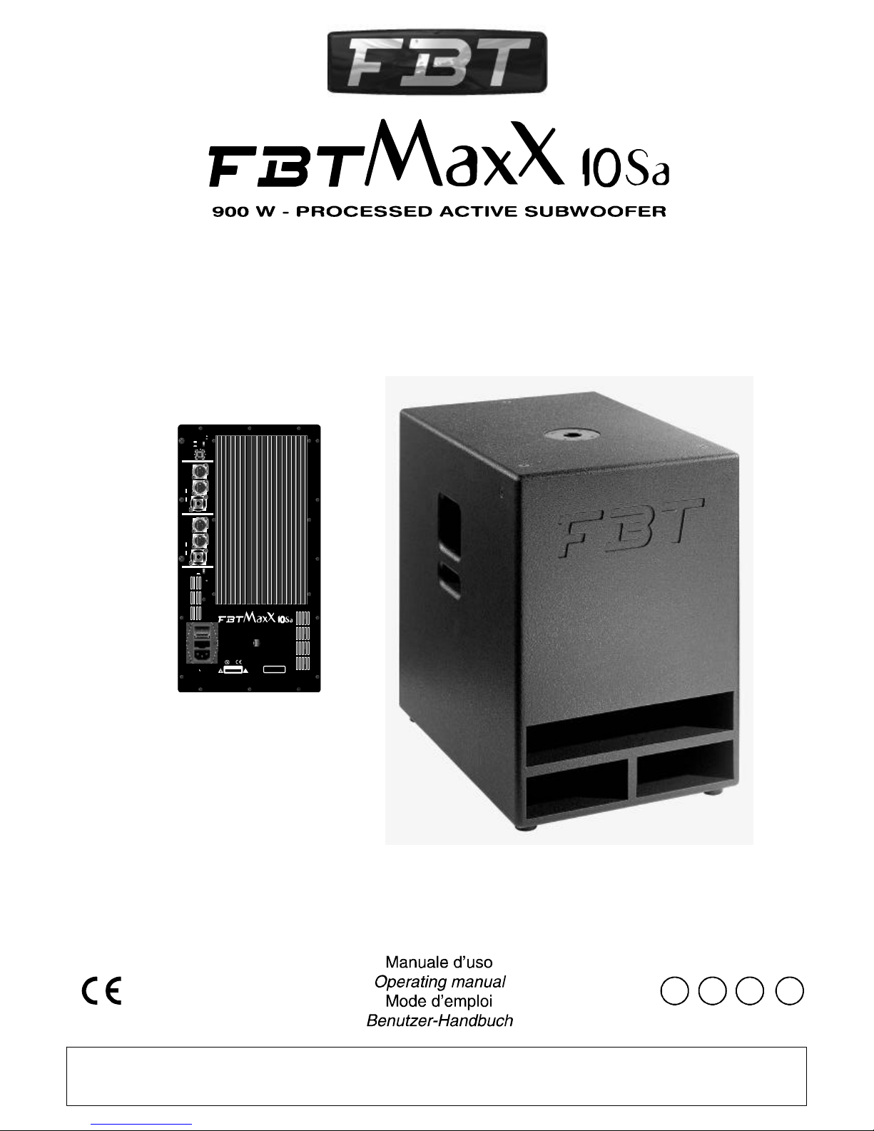
900W-PROCESSEDACTIVESUBWOOFER
PHASE
0°
180°
Page 2
AVVERTENZA
Perevitarefastidiosifenomenidiinnesco(effettoLarsen)oronzio,
assicuratevicheicavimicrofonicisianoschermatiecheimicrofoni
nonsianoorientatinelladirezionedellecasseacustiche.
WARNING
Toavoidanyannoyingfeedbackornoise(larseneffect),makesure
thatthemicrophonecablesarescreenedandthatmicrophonesare
neverpointedinthedirectionoftheloudspeakers.
PEREVITAREILRISCHIODISHOCKELETTRICO
NONAPRIREILCOPERCHIO
NONUSAREUTENSILIMECCANICIALL'INTERNO
CONTATTAREUNCENTRODIASSISTENZAQUALIFICATO
PEREVITAREILRISCHIODIINCENDIOODISHOCKELETTRICO
NONESPORREL'APPARECCHIATURAALLAPIOGGIA
OALL'UMIDITA'
RISCHIODISHOCKELETTRICO
NONAPRIRE
°Primadialimentareildiffusoreassicuratevichelatensionedi
alimentazionenonsiasuperioreaquellariportatanelpannelloposteriore
°Nonusatemail’apparecchioseilcavoolapresadiretenonsonoin
perfettecondizioni;evitatedipiegareeccessivamente,tirareotagliareil
cavodialimentazione;
°Perevitareilrischiodishockelettrici
°Nontoglietelaretemetallicadiprotezionedell’altoparlante:toccarlocon
oggettioconlestessemanipotrebbearrecaredanniirreparabili
°Perlapuliziadeldiffusorenonusatesolventitipoacetoneoalcoolche
danneggerebberolafinituraesterna
°Evitateditenereilsistemaespostoperlungotempoall’azionediagenti
atmosfericiqualiumidità,fortivariazioniditemperatura,eccessodicalore,
ecc.
°Evitatel’accumulodipolveree,perquantopossibile,proteggetelo,peril
trasporto,conilsuoimballooriginale
°Incasodicattivofunzionamentodiqualsiasidispositivodelsistema,
affidatevialpiùvicinocentrodiassistenzaFBToadunaltrocentro
specializzato,evitandodiprovvederepersonalmente
nonapriremaiildiffusore
Ilnuovosistemasub-wooferèrealizzatoin
multistratodibetullaverniciatoantigraffio.èun
connubioperfettotrapotenza,etecnologiad’avanguardiache
permettel’utilizzointuttiisistemidiamplificazioneaudio
professionaliperesaltarelebassefrequenze.Ilnuovosistema
A.D.A.P.(AdvancedDynamicActiveProtection)diprotezione
elettronicadeitrasduttori,assicuralamassimagaranziadi
funzionamentoinsituazionidiutilizzoimpossibiliperunnormale
diffusoresonoro.Ilfinaledipotenzapresenteall’internodella
progettatocontecnologiaPWM(PulseWidth
Modulation)permettediridurreilpesonelrapporto1:3,
raggiungendounaefficienzatrevoltesuperiorerispettoaduna
tecnologiatradizionale.L’altoparlantecustomèda380mmcon
bobinada75mm,magnetealneodimioultraleggeroeultrapotente,
cestelloinalluminiodie-cast.
FBTMaxX10SA
FBTMaxX10SA
FBTMaxX10SA,
INTRODUZIONE
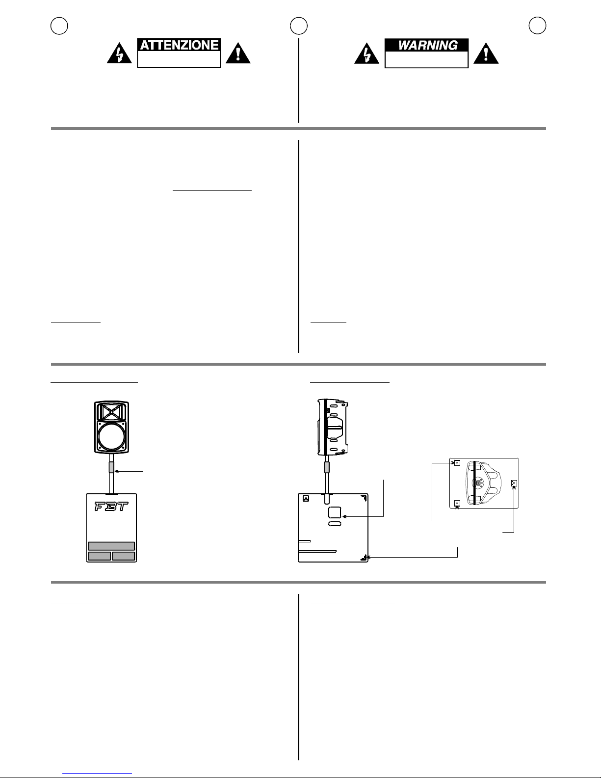
INSTALLAZIONE
INTRODUCTION
INSTALLATION
TOREDUCETHERISKOFELECTRICSHOCK
DONOTREMOVECOVER(ORBACK)
NOUSERSERVICEABLEPARTSINSIDE
REFERSERVICINGTOQUALIFIEDSERVICEPERSONNEL
TOREDUCETHERISKOFFIREORELECTRICSHOCK
DONOTEXPOSETHISEQUIPMENTTORAINORMOISTURE
RISKOFELECTRICSHOCK
DONOTOPEN
°Beforepoweringthespeakersystemmakesurethatthemainspower
voltageisnothigherthanthatshownontherearpanel
°Neverusetheapplianceifthepowercableorplugarenotinperfect
conditions;avoidexcessivebending,pullingorcuttingofthepowercable
°Topreventtheriskofelectricshockneverremovecover(orback)ofthe
speakersystem
°Donotremovethefrontmetalgrillewhichprotectstheloudspeaker;
avoidtouchingitwithanyserviceablepartstopreventanyirreparable
damage
°Donotusesolventssuchasacetoneoralcoholtocleanthesystem,as
theywoulddamageitsfinish
°Avoidexposingthesystemtotheactionofatmosphericagentsforalong
time(dampness,excessiveheat,strongtemperaturevariations,etc.)
°Cleanthesystemonceinawhiletoavoidexcessivedust;whenpossible
protectthesysteminsideitsoriginalpackagingforanytransportpurpose
°Intheeventofmalfunctionofanypartofthesystem,contactthenearest
FBTservicecentreorotherspecialisedcentres,butnevertrytocarryout
repairsyourself
I UK
1
4PUNTIDIANCORAGGIO
4ANCHORINGPOINTS
MANIGLIAINTEGRATA
BUILT-INHANDLE
mod.BOX50
SUPPORTOREGOLABILEPER
COLLEGAMENTOSUB-SATELLITE
mod.BOX50
ADJUSTABLEFORSUB-SATELLITE
SPEAKERCONNECTION
Thenewsubwoofersystemfeaturesan
enclosuremadeofbirchplywoodwithscratch-resistantfinish.The
constitutestheidealcombinationofpowerand
cutting-edgetechnologytoallowitsusewithallprofessionalaudio
amplificationsystemstoenhancebassfrequencies.Thenew
A.D.A.P.(AdvancedDynamicActiveProtection)driverprotection
systemensuresmaximumreliabilityofoperationevenin
situationsthatwouldbeunacceptablefornormalloudspeakers.
Thepoweramplifierincorporatedinthe
subwoofer,designedusingPulseWidthModulationtechnology,
enablesweight reductionintheratioof1:3,makingitpossibleto
obtainefficiencylevelsthatarethreetimesgreaterthanthose
availableusingconventionaltechnology.Thecustom380mm
driverisequippedwitha75mmcoilwithanultralighthigh-power
neodymiummagnetandadiecastaluminiumchassis.
FBTMaxX10SA
FBTMaxX10SA
FBTMaxX10SA
Page 3
#A.D.A.P.#
#PHASE#
#VOL#
#HPFILTEREDOUT#
#OUT-----LINK-----IN#
#GNDLIFT#
#PWR#
#PRESADIALIMENTAZIONE#
Processoreperlaprotezionedei
trasduttoridalleeccessivetensioni;quandoil
segnaleaudioraggiungelasogliadipericoloperi
componenti,ilsistemaintervieneautomaticamente
attenuandolatensionedelsegnale,riportandoloal
disottodeilimiti:itempidireazionedelsistemasono
rapidissimi.L’entratainfunzionedelprocessoreè
segnalatadall’accensionedelled.
Switchcheconsentediottimizzare
l’allineamentodifase,cioèdiottenereunarisposta
infrequenzauniformenellazonadiincrociotrasube
satellite.
Potenziometrodivolumecheregolail
livellogeneraledelsegnale.
Uscitaperprelevareil
segnalefiltratodainviareadunsatelliteamplificato.
Inquestomodosievitacheiduediffusoricollegati
operinoperuntrattonellostessointervallodi
frequenza,ottenendounarispostacomplessiva
senzainterferenze.
Presediingressoeduscita
bilanciateelettronicamente.Lapresadiingressodel
tipoComboaccettasiaconnettoriJackcheXLR-M,
perlaconnessionedistrumenticonsegnali
preamplificatisbilanciatiobilanciati(comequelliin
uscitadiunmixer).LapresadiuscitaXLRpuò
essereutilizzatacomecollegamentoperunsatellite
(consegnalenonfiltrato)
(in
questocasoilcollegamentoconunsatellitepuò
avveniresoloattraversolapresaXLR“HP
FILTEREDOUT”.
Interruttoreperlaseparazione
elettricatrailcircuitodimassaeilcircuitoditerra.
Conilpulsantepremutolamassadeisegnaliin
ingressovieneelettricamentescollegatadalcircuito
diterra(identificatonellochassis);nelcasosi
manifestiunronziosuldiffusore,questaposizione
provvedeadapriregli“anellidimassa”,spesso
causaditalidisturbi.Conilpulsanterilasciatola
massadeisegnaliiningressovieneelettricamente
collegataalcircuitoditerradell’apparecchio
(identificatonellochassis).
Ledchesegnalal’accensionedelsistema.
Comprende
l’interruttorediaccensionedelsistema,lapresaper
ilcollegamentoallareteelettricael’alloggiamento
delfusibilediprotezionedelcircuitodi
alimentazione:incasodirotturadelfusibile,
quest’ultimovasostituitosolodafusibiliconuguali
caratteristichetecniche.
pereffettuareil
collegamentoinparalleloconaltrisub-woofers
UTILIZZAREIL
GROUNDLIFTSOLOPERSEGNALIBILANCIATI.
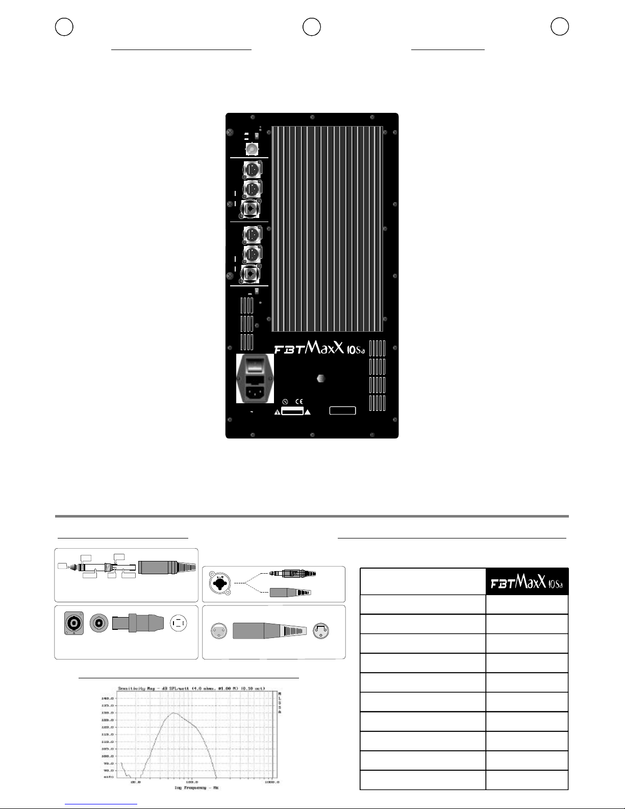
CONNESSIONI/CONNECTIONS SPECIFICHETECNICHE/TECHNICALSPECIFICATIONS
PANNELLOPOSTERIORE REARPANEL
LatosaldatureLatocontatti
1.Massa2.Fase+3.Fase-Schermo(Shield)Caldo(Hot)Freddo(Cold)
1+ PositivePositivo/
1- NegativeNegativo/
PresaSpeakon
Jackstereo/bilanciato/balanced
#A.D.A.P.#
#PHASE#
#VOL#
#HPFILTEREDOUT#
#OUT-----LINK-----IN#
#GNDLIFT#
#PWR#
#POWERSOCKET#
Processorforprotectingtransducers
againstovervoltages;whenthesoundsignal
reachesthedangerlimitforthecomponents,the
systemcutsinautomaticallyattenuatingthesignal
voltage,bringingitdownunderthelimit:system
responsetimesareveryfast.Theinputonfromthe
processorissignalledbytheledlightingup.
Switchtooptimisephasealignment,i.e.
toobtainauniformfrequencyresponseinthe
crossoverareabetweensubwooferandsatellites.
Volumepotentiometerwhichadjuststhe
generallevelofthesignal.
Outputtopickupthefiltered
signaltobesenttoasatellite.Thispreventsthetwo
connectedspeakersfromoperatingforaperiodin
thesamefrequencyrange,obtainingatotal
responsewithoutinterference.
Electronicallybalanced
inputandoutputsockets.TheCombotypeinput
sockettakesbothJackconnectorsandXLR-M
connectors,forconnectinginstrumentswith
unbalancedorbalancedpreamplifiedsignals(like
thosefromamixer).TheXLRoutputsocketcanbe
usedasconnectionforasatellite(withunfiltered
signal)formakingparallelconnectionwithother
sub-woofers(inthiscasesatelliteconnectioncan
occuronlythroughtheXLR“HPFILTEREDOUT”
socket).
ISwitchforelectricalseparation
betweenthemasscircuitandtheearthcircuit.With
thepushbuttonispressedthemassoftheinput
signalsiselectricallydisconnectedfromtheearth
circuit(identifiedinthechassis);incaseof
hummingonthespeaker,thispositionopensthe
“massrings”,whichareoftenthecauseofsuch
interference.Withthepushbuttonreleasedthe
massoftheinputsignalsiselectricallyconnectedto
theearthcircuitoftheunit(identifiedinthechassis
).USETHEGROUNDLIFTONLYFOR
BALANCEDSIGNALS.
Ledsignalssystemon.
IncludesthesystemOn
switch,thesocketforconnectiontothepower
mainsandholdsthepowersupplycircuitprotection
fuse:ifthefuseblowsitmustonlybereplacedwith
fusesofequaltechnicalcharacteristics.
I UK
2
Configurazione
Type
ventedbandpass
900
36Hz-120Hz
100
129,5
1x380
460x630x640
41
5
XLR-M-combo
Amplificatoreinterno
Built-inamplifier
Wrms
@-5dB
@1W/1mdB
dB
mm
m
(LxAxP)mm
(WxHxD)mm
kg.
vie/way
Rispostainfrequenza
Frequencyresponse
Sensibilità
Sensitivity
MassimoSPL
MaximumSPL
Unitàbassefrequenze
Lowfrequencywoofer
Dimensioni
Dimensions
Peso
Weight
Connettoridiingresso
Inputconnectors
Cavodialimentazione
Powersupplycable
0 10
VOL
OUT
R
L
OUT
LINK
LINK
IN
IN
PWR
GND
LIFT
HP
FILTERED
OUT
HP
FILTERED
OUT
T3.15A250V
650VA50Hz230V
!
CAUTION
RISKOFELECTRICSHOCK
DONOTOPEN
MADE
IN
ITALY
FREQ.RANGE:
MAX.SPL:
36Hz-120Hz
129.5dB
CODE18586 MAXX10SA
ADAP
R
900W-PROCESSEDACTIVESUBWOOFER
PHASE
0°
180°
12
21
33
XLR
Speakon*
1+
2+
2- 1-
XLR-F(mic)
1=SHIELD
2=HOT
3=COLD
LINE
JACK
12
3
NEUTRIKXLR/JACK-COMBO
TIP=Positive(+orhot)
SLEEVE=Shieldorground
RING=Negative(-orcold)
TIP
TIP
RING
RING
SLEEVE
SLEEVE
RISPOSTAINFREQUENZA/FREQUENCYRESPONSE
*SPEAKONèunmarchioregistratoNEUTRIK
*SPEAKONisaregistredtrademarkofNEUTRIK
Page 4

ESEMPIDICOLLEGAMENTO CONNECTIONEXAMPLES
IN
ININ
IN
USCITA
FILTRATA
FILTERED
OUT
USCITAFILTRATA
USCITAFILTRATA
FILTEREDOUT
FILTEREDOUT
Rchannel
canaledx
Lchannel
canalesx
USCITA
FILTRATA
FILTERED
OUT
FBTMaxX2a
FBTMaxX4a
o/or
FBTMaxX10SA
FBTMaxX2a
FBTMaxX4a
o/or
FBTMaxX10SA
MIXER
MIXER
FBTMaxX10SA
FBTMaxX10SA FBTMaxX10SA
IN
IN
USCITAFILTRATAINPOTENZA
FILTEREDOUT(POWER)
FBTMaxX2
FBTMaxX4
o/or
FBTMaxX2
FBTMaxX4
o/or
I UK
3
FBTMaxX2a
FBTMaxX4a
o/or
FBTMaxX2a
FBTMaxX4a
o/or
0 10
VOL
OUT
R
LOUT
LINK
LINK
IN
IN
PWR
GND
LIFT
HP
FILTERED
OUT
HP
FILTERED
OUT
ADAP
R
PHASE
0°
180°
0 10
VOL
OUT
R
LOUT
LINK
LINK
IN
IN
PWR
GND
LIFT
HP
FILTERED
OUT
HP
FILTERED
OUT
ADAP
R
PHASE
0°
180°
0 10
VOL
OUT
R
LOUT
LINK
LINK
IN
IN
PWR
GND
LIFT
HP
FILTERED
OUT
HP
FILTERED
OUT
ADAP
R
PHASE
0°
180°
0 10
VOL
OUT
R
LOUT
LINK
LINK
IN
IN
PWR
GND
LIFT
HP
FILTERED
OUT
HP
FILTERED
OUT
ADAP
R
PHASE
0°
180°
0 10
VOL
OUT
R
L
OUT
LINK
LINK
IN
IN
PWR
GND
LIFT
HP
FILTERED
OUT
HP
FILTERED
OUT
ADAP
R
PHASE
0°
180°
Page 5

AVERTISSEMENTS
Evitezd’orienterlesmicrosdansladirectiondesbafflesacoustiques,
carilspourraientprovoquerdesamorcesgênantes(effetlarsen)qui
risqueraientd’endommagerleshaut-parleurs
ACHTUNG
VermeidenSiedieAusrichtungderMikrophoneinRichtungder
Boxen:dieMikrophonekönntenlästigeSchwingungenerzeugen
(Larseneffekt),dieLautsprecherbeschädigenkönnten
POURÉVITERLERISQUEDECHOCÉLECTRIQUE
NEPASOUVRIRLECOUVERCLE
NEPASUTILISERD’OUTILSMÉCANIQUESÀL’INTÉRIEUR
CONTACTERUNCENTRED’ASSISTANCEQUALIFIÉ
POURÉVITERLERISQUED’INCENDIEOUDECHOCÉLECTRIQUE
NEPASEXPOSERL’APPAREILLAGEÀLAPLUIEOUÀL’HUMIDIT
RISQUEDECHOCÉLECTRIQUE
NEPASOUVRIR
°Vérifiezquelatensiond’alimentationnesoitpassupérieureàlavaleur
indiquéederrièrel’appareil
°Pouréviterlesrisquesd’incendieetd’électrocution,veillezàcequele
câbled’alimentationdel’enceintenesoitnipiétinéniécraséetqu’ilreste
parfaitementindemne.
°Pouréviterlesrisquesdechocélectriques,
°Evitezdetoucherlescônesdeshauts-parleursdesavecl’unoul’autre
objectouaveclesmains,cardesdommagesirréparablespourraientse
produire
°Pourlenettoyagedesbafflesn’utilisezpasdesolvantsdutypeacétone
oualcool,carilspourraientendommagerlesfinitionsextérieures
°Evitezdelaisserexposertroplongtempslesbafflesàl’actiondesagents
atmosphériques(humidité,fortesvariationsdetempérature,excèsde
chaleur,etc...)
°Evitezl’accumulationdepoussièreetpourletransportprotégez-les,si
possible,avecleuremballaged’origine
°Encasdemauvaisfonctionnementd’undesdispositifsdusystème,
adressez-vousaucentred’assistanceFBTleplusprocheouàuncentre
spécialiséetévitezd’intervenirpersonnellement
n’ouvrezjamaisl’enceinte.
INTRODUCTION
INSTALLATION
EINLEITUNG
INSTALLATION
STROMSCHLAGGEFAHRNICHTDENDECKELÖFFNEN
WENDENSIESICHANEINENQUALIFIZIERTENKUNDENDIENST
UMRISIKENVONSTROMSCHLAGUNDBRANDAUSZUSCHLIESSEN
SETZENSIEDASGERÄTKEINEMREGENODERFEUCHTIGKEITAUS
STROMSCHLAGGEFAHR
NICHTÖFFNEN
°VordemSpeisenderLautsprecherboxsicherstellen,dasihre
BetriebsspannungmitderNetzspannungübereinstimmt
°BenutzenSiedasGerätnie,wenndasKabeloderderNetzsteckersich
nichtinoptimalemZustandbefinden
°OffnenSiedieLautsprecherboxnie,umdieGefahrvonelektrischen
Schlägenzuvermeiden
°VermeidenSie,dieKegelderLautsprechermitirgndeinemGegenstand
odermitdenHändenzuberühren:eskönntennichtreparierbareSchäden
entstehen
°ZurReinigungderBoxenbenutzenSiebittekeineLösemittelwieAlkohol
oderAzeton,dadiesederAußenschichtunddemFilmdruckaufden
Schalltafelnschadenwürden
°VermeidenSie,dieakustischenBoxenfürlängereZeitden
Witterungseinflüssenauszusetzen(Feuchtigkeit,starke
Temperaturschwankungen,ÜbermaßanHitzeusw.)
°VermeidenSieebensostarkeStaubansammlungenundbenutzenSie,
soweitwiemöglich,dieOriginalverpackungfürdenTransport
°ImFalleeinesfehlerhaftenAblaufseinerdervorhandenen
EinrichtungendesSystems,wendensiebitteandennächstliegenden
KundendienstderFBToderaneinFachgeschäft;vermeidenSie
Eigenreparaturen
F D
4
4POINTSDEFIXATION
VIERVERANKERUNGSPUNKTE
POIGNÉEINTÉGRÉE
INTEGRIERTERTRAGEGRIFF
mod.BOX50
RÉGLABLEPOURRACCORDEMENT
SUB-SATELLITE
mod.BOX50
REGULIERBARERSTÄNDERFÜR
SUB-SATELLITE
Lenouveausystèmesub-wooferestréaliséen
bouleauverniantigriffuremulticouches.
représentelemariageparfaitentrepuissanceettechnologie
d'avant-garde,pouvantêtreutilisédanstouslessystèmes
d'amplificationaudioprofessionnelspourmettreenvaleurles
bassesfréquences.LenouveausystèmeADAP(Advanced
DynamicActiveProtection,c'est-à-diredeprotectionélectronique
destransducteurs)garantitunfonctionnementparfaitdanstoutes
lessituationsd'utilisation,mêmelesplusdifficilespourune
enceinteacoustiquenormale.L'étagefinaldepuissance,monté
danslesub-woofer,adoptelatechnologiePWM
(PulseWidthModulation-Modulationàlargeurdesimpulsions):
ellepermetderéduirededeuxtierslepoids,toutenatteignantune
efficacitétroisfoissupérieureàcelledelatechnologie
traditionnelle.Lehaut-parleurcustomestun380mmavecbobine
de75mm,aimantau"néodymium"ultra-légeretultra-puissant,
panierenaluminiummoulésouspression.
FBTMaxX10SA
FBTMaxX10SA
FBTMaxX10SA
DasneueSubwoofer-Systemistaus
vielschichtigemBirken-SperrholzmitkratzfesterLackierung
gefertigt.istdieperfekteSyntheseausLeistung
undzukunftsweisenderTechnologieundfürdenEinsatzinallen
professionellenAudio-VerstärkersystemenzurTiefenanhebung
geeignet.DasneueelektronischeADAP(AdvancedDynamic
ActiveProtection)-SchutzsystemderLautsprechersorgtfür
höchsteBetriebssicherheitselbstinSituationen,indenennormale
Boxen“passen”müssen.DiemitPWM-Technologie(PulseWidth
Modulation)entwickelteLeistungs-EndstufederSerie
ermöglichteineGewichtsreduzierungim
Verhältnis1:3undsomitdiedreifacheEffizienzgegenüber
herkömmlicherTechnologie.DerCustom-Lautsprecher380mm
istmiteiner75mm-Spule,einemultraleichtenundultrastarken
Neodym-MagnetundeinemKorbausSpritzgussaluminium
ausgestattet.
FBTMaxX10SA
FBTMaxX10SA
FBTMaxX10SA
Page 6

#ADAP#
#PHASE#
#VOL#
#HPFILTEREDOUT#
#OUT-----LINK-----IN#
#GNDLIFT#
#PWR#
#PRISED'ALIMENTATION#
Processeurservantàprotégerles
transducteurscontrelestensionsexcessives;
lorsquelesignalaudioatteintleseuildedangerpour
lescomposantsdusystème,ilsedéclenche
automatiquementetréduitlatensiondusignalpourle
ramenerendessousdeslimites:lestempsde
réactiondusystèmesonttrèsrapides.Uneled
s'allumelorsqueleprocesseurentreenfonction.
Interrupteurquipermetd’optimiser
l’alignementdelaphase,etdoncd’obtenirune
réponseenfréquenceuniformedanslazonede
croisemententrelesubetlesatellite.
Potentiomètreduvolumeréglantleniveau
généraldusignal.
Sortiepermettantdeprélever
lesignalfiltréàenvoyeràunsatellite.Onéviteainsi
quelesdeuxdiffuseursconnectéstravaillenten
partiedanslemêmeintervalledefréquenceeton
obtientuneréponseglobalesansinterférences.
Prisesd'entréeetdesortie
équilibréesélectroniquement.Laprised'entrée,de
typeCombo,accepteaussibienlesconnecteurs
JackqueXLR-M,pourlaconnexiond'instruments
avecsignauxpréamplifiéséquilibrés(commeceux
quisortentd'unmixeur)ounon.Laprisedesortie
XLRpeutêtreutiliséepourconnecterunsatellite
(avecsignalnonfiltré)poureffectuerlaconnexionen
parallèleavecd'autressub-woofers(danscecas,la
connexionavecunsatellitepeutsefaireuniquement
àtraverslapriseXLR“HPFILTEREDOUT”).
Interrupteurpourlaséparation
électriquedescircuitsdemasseetdeterre.Sion
appuiesurlebouton,lamassedessignauxd'entrée
estdéconnectéeélectriquementducircuitdeterre
(indiquédanslechâssis);danslecasde
bourdonnementdel'enceinte,cettepositionouvreles
“anneauxdemasse”,quisontsouventlacausede
cesparasites.Lorsqueleboutonestrelâché,la
massedessignauxd'entréeestreliéeé
lectriquementaucircuitdeterredel'appareil(indiqué
danslechâssis).UTILISERLEGROUNDLIFT
UNIQUEMENTPOURLESSIGNAUXÉQUILIBRÉS.
Laledsignalequelesystèmeestsous
tension.
Elleestforméepar
l'interrupteurmarche/arrêtdusystème,laprisepour
laconnexionausecteuretlelogementdufusiblede
protectionducircuitd'alimentation;remplacerle
fusiblefonduparunneufayantlesmêmes
caractéristiquestechniques.
#ADAP#
#PHASE#
#VOL#
#HPFILTEREDOUT#
#OUT-----LINK-----IN#
#GNDLIFT#
#PWR#
#VERSORGUNGSANSCHLUSS#
SchutzprozessorderTransmittervor
Überspannungen;wenndasAudiosignaldie
GefahrenschwellefürdieKomponentenerreicht,
greiftdasSystemautomatischdurchAbschwächen
derSignalspannungunterdieGrenzwerteein:Die
AnsprechzeitdesSystemsistäußerstkurz.Die
EinschaltungdesProzessorswirddurchAufleuchten
derLedgemeldet.
SwitchzurOptimierungdes
Phasengangs,umeinengleichmäßigen
FrequenzverlaufimSub-Satellite-CrossoverBereichzuerhalten.
PotentiometerzurRegelungdes
allgemeinenLautstärke-Signalpegels.
AusgangzurEntnahmedes
aneinenSatellitenzusendendengefiltertenSignals.
AufdieseWeisewirddieFunktionderbeiden
angeschlossenenLautsprecherimgleichen
Frequenzbereichverhindertundeinestö
rungsfreieGesamtwiedergabeerzielt.
ElektronischbalancierteEinundAusgangsbuchsen.DieEingangsbuchsevom
TypCombounterstütztsowohlJack-alsauchXLRM-SteckerzumAnschlussvonGerätenmit
vorverstärktennichtbalanciertenbzw.balancierten
Signalen(wiedieAusgangssignalseines
Mischpults).SiekönnendieXLRAusgangsbuchse
zumAnschlusseinesSatelliten(mitnichtgefiltertem
Signal)inParallelschaltungmitanderenSubwoofern
verwenden(indiesemFallistderAnschlussaneinen
SatellitennurmitderXLR"HPFILTEREDOUT"
Buchsemöglich).
SchalterzurelektrischenTrennung
vonMasse-undErdkreis.BeigedrückterTastewird
dieMassederEingangssignaleelektrischvondem
(imChassisgekennzeichneten)Erdkreisgetrennt;
solltederLautsprecherbrummen,öffnensichinder
Position"on"die"Massekreise"alshäufigste
UrsachedieserStörung.BeiausgerasteterTastewird
dieMassederEingangssignaleelektrischmitdem
(imChassisgekennzeichneten)Erdkreisverbunden.
VERWENDENSIEGROUNDLIFTNURIMFALL
BALANCIERTERSIGNALE.
LedzurAnzeigederSystemeinschaltung.
Schließtden
SchalterzumSystembetrieb,dieAnschlussbuchse
andasStromnetzsowiedieAufnahmefürdie
SchutzsicherungdesStromkreisesein:ErsetzenSie
beschädigteSicherungennurdurchsolchemit
gleichentechnischenKennwerten.
BRANCHEMENTS/ANSCHLÜSSE CARACTÉRISTIQUESTECHNIQUES/TECHNISCHEDATEN
PANNEAUARRIÈRE RÜCKWAND
12
21
33
Côtésoudures
Geschlosseneseite
Côtécontacts
Kontaktseite
1.Massa2.Fase+3.Fase-(Shield)(Hot)(Cold)
XLR
1+ Positive
1- Negative
Speakon*
PriseSpeakon
SpeakonStecker
1+
2+
2- 1-
XLR-F(mic)
1=SHIELD
2=HOT
3=COLD
LINE
JACK
12
3
NEUTRIKXLR/JACK-COMBO
Stereojackbalancée
Stereobuchse
TIP=Positive(+orhot)
SLEEVE=Shieldorground
RING=Negative(-orcold)
TIP
TIP
RING
RING
SLEEVE
SLEEVE
F D
5
Configuration
Konfiguration
Amplificateurinterne
IntegriertenVerstärker
Wrms
@-5dB
@1W/1mdB
dB
mm
m
(LxAxP)mm
(BxHxT)mm
kg.
voies/weg
Réponseenfréquence
Frequenzgang
Sensibilité
Empfindlichkeit
MaximumSPL
Maximalershalldruck
Wooferbassesfréquence
Bass-Woofer
Dimensions
Abmessungen
Poids
Gewicht
Connecteurs
Eingange
Câblesd’alimentation
Stromversorgungskabel
ventedbandpass
900
36Hz-120Hz
100
129,5
1x380
460x630x640
41
5
XLR-M-combo
0 10
VOL
OUT
R
L
OUT
LINK
LINK
IN
IN
PWR
GND
LIFT
HP
FILTERED
OUT
HP
FILTERED
OUT
T3.15A250V
650VA50Hz230V
!
CAUTION
RISKOFELECTRICSHOCK
DONOTOPEN
MADE
IN
ITALY
FREQ.RANGE:
MAX.SPL:
36Hz-120Hz
129.5dB
CODE18586 MAXX10SA
ADAP
R
900W-PROCESSEDACTIVESUBWOOFER
PHASE
0°
180°
RÉPONSEENFRÉQUENCE/FREQUENZGANG
*SPEAKONestunemarquedéposéeNEUTRIK
*SPEAKONisteineingetragenesWarenzeichenvonNEUTRIK
Page 7

EXEMPLESDECONNEXION ANSCHLUSSBEISPIELE
ou/oder
ou/oder
IN
IN
FBTMaxX2a
FBTMaxX4a
FBTMaxX10SA
FBTMaxX2a
FBTMaxX4a
FBTMaxX10SA
MIXER
SORTIE
FILTRÉE
GEFILTERTEM
AUSGANG
ou/oder ou/oder
FBTMaxX10SA FBTMaxX10SA
FBTMaxX2
FBTMaxX4
ou/oder ou/oder
FBTMaxX2
FBTMaxX4
F D
6
SORTIEFILTRÉE
GEFILTERTEMAUSGANG
IN
IN
ININ
RchannelLchannel
MIXER
FBTMaxX10SA
FBTMaxX2a
FBTMaxX4a
FBTMaxX2a
FBTMaxX4a
0 10
VOL
OUT
R
L
OUT
LINK
LINK
IN
IN
PWR
GND
LIFT
HP
FILTERED
OUT
HP
FILTERED
OUT
ADAP
R
PHASE
0°
180°
SORTIEFILTRÉE
GEFILTERTEMAUSGANG
SORTIEFILTRÉE
GEFILTERTEM
AUSGANG
0 10
VOL
OUT
R
L
OUT
LINK
LINK
IN
IN
PWR
GND
LIFT
HP
FILTERED
OUT
HP
FILTERED
OUT
ADAP
R
PHASE
0°
180°
0 10
VOL
OUT
R
L
OUT
LINK
LINK
IN
IN
PWR
GND
LIFT
HP
FILTERED
OUT
HP
FILTERED
OUT
ADAP
R
PHASE
0°
180°
0 10
VOL
OUT
R
L
OUT
LINK
LINK
IN
IN
PWR
GND
LIFT
HP
FILTERED
OUT
HP
FILTERED
OUT
ADAP
R
PHASE
0°
180°
0 10
VOL
OUT
R
L
OUT
LINK
LINK
IN
IN
PWR
GND
LIFT
HP
FILTERED
OUT
HP
FILTERED
OUT
ADAP
R
PHASE
0°
180°
Page 8

Leinformazionicontenuteinquestomanualesonostatescrupolosamentecontrollate;tuttavianonsiassumenessuna
responsabilitàpereventualiinesattezze.LaFBTElettronicaS.p.A.siriservaildirittodimodificarelecaratteristichetecniche
edestetichedeiprodottiinqualsiasimomentoesenzapreavviso.
Allinformationincludedinthisoperatingmanualhavebeenscrupulouslycontrolled;howeverFBTisnotresponsiblefor
eventualmistakes.FBTElettronicaS.p.A.hastherighttoamendproductsandspecificationswithoutnotice.
Lesinformationscontenuesdanscemanuelontétésoigneusement;toutefoisleconstructeurn’estpasresponsable
d’éventuellesinexactitudes.LaFBTElettronicaS.p.A.s’octroieledroitdemodifierlesdonnéestechniquesetl’aspect
esthétiquedesesproduitssansavispréalable.
AlleinformationenindieserBedienungsanleitungwurdennachbestemWissen;Daherkönnensiealszuverlässigangesehen
werden.FüreventuelleFehlerûbernimmtFBTaberkeineHaftung.FBTElettronicaS.p.A.BehältsichdasRechtaufÄnderung
derProdukteundSpezifikationenvor.
CODE19117
 Loading...