


564
REV LEVEL 04: 02/25/14
FBD Part Number: 24-2280-0001
NOTICE:
The information contained in this document is subject to change without notice.
FBD MAKES NO WARRANTY OF ANY KIND WITH REGARD TO THIS MATERIAL, INCLUDING, BUT NOT
LIMITED TO, THE IMPLIED WARRANTIES OF MERCHANTABILITY AND FITNESS FOR A PARTICULAR
PURPOSE. FBD shall not be liable for errors contained herein or for incidental consequential damages in connection
with the furnishings, performance, or use of this material.
This document contains proprietary information which is protected by copyright. All rights reserved.
©2014 FBD Partnership, LP. All Rights Reserved.
This manual supersedes and replaces 24-2280-0001/Rev 03, dated 03/27/12,
and is designated as Revision 04.
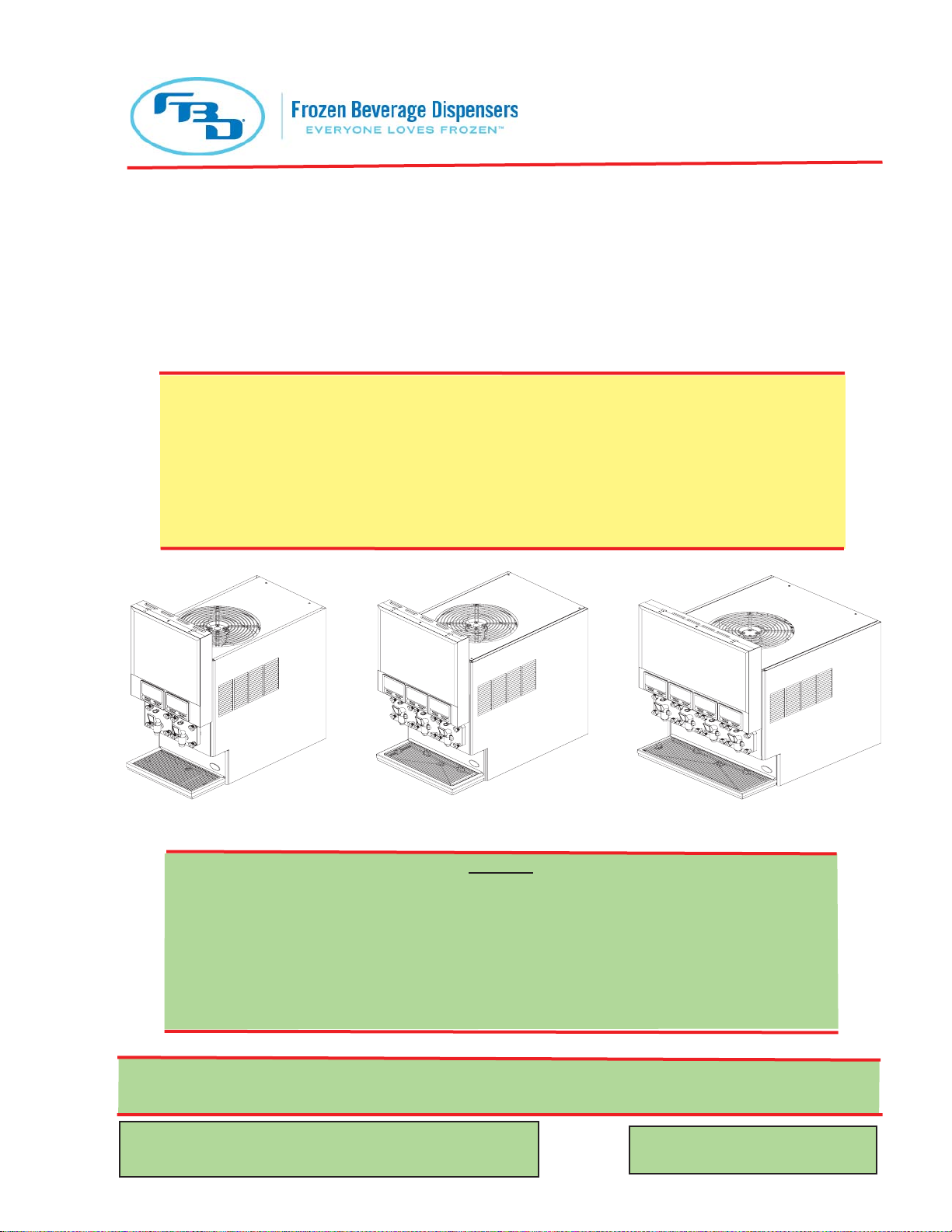
THIS MANUAL APPLIES TO FROZEN BEVERAGE DISPENSERS
IN THE 562, 563 AND 564 SERIES.
THIS DOCUMENT CONTAINS IMPORTANT INFORMATION.
This manual must be read and understood
BEFORE the installation and operation of the dispenser.
FBD562
FBD563
FBD564
Please refer to the FBD web site (www.fbdfrozen.com) for information
relating to FBD Installation, Operation and Service Manuals, Instruction
Sheets, Technical Bulletins, Service Bulletins, etc.
FBD Partnership, LP
• P.O. BOX 18597 • SAN ANTONIO, TX 78218 USA •
• 210-637-2800 • FAX 210-637-2844 • www.fbdfrozen.com •
• FBD TECHNICAL SUPPORT • 1-866-323-2777 •
• TECHNICAL SUPPORT FAX 1-210-637-2832 •
INSTALLATION AND OPERATION MANUAL
FOR THE
MODEL FBD56X SERIES
FROZEN BEVERAGE DISPENSERS

2
SPECIFICATIONS FOR THE FBD562 DISPENSER
DIMENSIONS
Width 17.0 inches (432 mm)
Depth 32.3 inches (820 mm)
Height (Standard Countertop Unit) 41.4 inches (1054 mm)
Height (Optional Roll Around Unit/Stand) 75.4 inches (1918 mm)
WEIGHT
Shipping 395 pounds (179.2 kg)
Empty 318 pounds (144.2 kg)
Operational 345 pounds (156.5 kg)
WATER REQUIREMENTS
Minimum flowing pressure 30 psig (207.0 kPag)
Maximum static pressure 70 psig (483.0 kPag)
CARBON DIOXIDE (CO2) REQUIREMENTS
Minimum pressure 70 psig (482.6 kPag)
Maximum pressure 72 psig (496.4 kPag)
SPECIFICATIONS FOR THE FBD563 DISPENSER
DIMENSIONS
Width 20.3 inches (516 mm)
Depth 32.3 inches (820 mm)
Height (Standard Countertop Unit) 41.4 inches (1054 mm)
Height (Optional Roll Around Unit/Stand) 75.4 inches (1918 mm)
WEIGHT
Shipping 415 pounds (188.2 kg)
Empty 365 pounds (166.0 kg)
Operational 390 pounds (177.0 kg)
WATER REQUIREMENTS
Minimum flowing pressure 30 psig (207.0 kPag)
Maximum static pressure 70 psig (483.0 kPag)
CARBON DIOXIDE (CO2) REQUIREMENTS
Minimum pressure 70 psig (482.6 kPag)
Maximum pressure 72 psig (496.4 kPag)

3
SPECIFICATIONS FOR THE FBD564 DISPENSER
DIMENSIONS
Width 26.0 inches (660 mm)
Depth 32.3 inches (820 mm)
Height (Standard Countertop Unit) 41.4 inches (1054 mm)
Height (Optional Roll Around Unit/Stand) 75.4 inches (1918 mm)
WEIGHT
Shipping 500 pounds (226.8 kg)
Empty 410 pounds (185.9 kg)
Operational 460 pounds (208.7 kg)
WATER REQUIREMENTS
Minimum flowing pressure 30 psig (207.0 kPag)
Maximum static pressure 70 psig (483.0 kPag)
CARBON DIOXIDE (CO
2) REQUIREMENTS
Minimum pressure 70 psig (482.6 kPag)
Maximum pressure 72 psig (496.4 kPag)
SAFETY PRECAUTIONS
We at FBD are concerned about your safety. Please carefully read the following precautions before working with
the FBD56x units. This will familiarize you with proper equipment handling techniques.
LIFTING
• To avoid personal injury or damage, do not attempt to lift the unit without help. The use of a
mechanical lift is recommended
•• The empty FBD562 unit weighs approximately 318 pounds (144.2 kg).
•• The empty FBD563 unit weighs approximately 365 pounds (166.0 kg).
•• The empty FBD564 unit weighs approximately 410 pounds (185.9 kg).
• Use gloves to protect hands from being injured by the edges of cross bracing if lifting by hand.
• Use proper equipment and lifting techniques when lifting or moving equipment. The unit is top heavy.
Maintain unit in a vertical, upright position when lifting and positioning the unit.
ELECTRICAL
• This unit must be properly electrically grounded to avoid possible fatal electrical shock or serious
injury to the operator. The power cord is provided with a three prong grounded plug. If a three-hole
grounded electrical outlet is not available, use an approved method to ground the unit. Only qualified
electricians should perform this task and the work performed should meet all applicable codes.
• Always disconnect electrical power to the unit to prevent personal injury before attempting any
internal maintenance. Only qualified personnel should service internal components of electrical
wiring.
CARBON DIOXIDE (CO2)
• CO
2 (carbon dioxide) displaces oxygen. Strict attention must be observed in the prevention of CO2
gas leaks in the entire CO2 and soft drink system. If a CO2 gas leak is suspected, immediately
ventilate the contaminated area before attempting to repair the leak. Personnel exposed to high
concentrations of CO2 gas will experience tremors which are followed rapidly by loss of
consciousness and suffocation.
• To avoid personal injury and/or property damage, always secure CO
2 cylinders in an upright
position with a safety chain to prevent cylinders from falling over. Should the valve become accidentally
damaged or broken off, a CO2 cylinder can cause serious personal injury.

4
QUICK REFERENCE SHEET
FOR INSTALLING FBD UNITS
NOTE:
This guide is for quick reference only. It is not intended to replace important detailed information
contained in this Installation, Operation and Service Manual. Thoroughly read the entire manual
before attempting installation.
Checkpoints
Verify the line voltage is between 215 VAC and 245 VAC.
Adjust the voltage offset to make the line voltage and the voltage on the display
match.
Adjust the CO2 secondary regulator to between 28 and 32 psig.
NOTE:
If this is a low carbonation application, the CO2 secondary regulator should be set to between
17 and 19 psig and requires special software.
Verify on the unit’s display that the CO2 and syrup pressures are at about 70 psig
static.
Verify the water pressure is about 70 psig static for a SHURfl o pump and between
85 and 90 psig for a Flojet pump.
Adjust the water fl ow rate to 1.5 ounces per second.
Adjust the Brix to between 13.5 and 15.0.
Fill barrels with product.
Press “DEF” and then “RUN” for each barrel. There will be a two (2) minute
delay before the compressor starts. The freeze down will take between 8 to 10
minutes.
See Sections 4 through 6 of this manual for further details on each of these
checkpoints and dispenser installation.
NOTE:
If the unit has been in storage for longer than 90 days, FBD recommends that the rear seals be replaced.
5
OPERATING REQUIREMENTS
550: 345 LB (156 Kg)
562: 345 LB (156 Kg)
553: 370 LB (168 Kg)
563: 390 LB (177 Kg)
564: 460 LB (209 Kg)
554: 634 LB (288 Kg)
550: 215-245 VAC, 30 A, 1 PH
562: 215-245 VAC, 20 A, 1 PH
553: 215-245 VAC, 30 A, 1 PH
563: 215-245 VAC, 20 A, 1 PH
564: 215-245 VAC, 30 A, 1 PH
554: 215-245 VAC, 50 A, 1 PH

TABLE OF CONTENTS
SPECIFICATIONS ..........................................................................................................................................2-3
SAFETY PRECAUTIONS ..................................................................................................................................3
QUICK REFERENCE SHEET FOR INSTALLING FBD UNITS .....................................................................4-5
TABLE OF CONTENTS ..................................................................................................................................6-7
1. PREPARING THE LOCATION ...................................................................................................................7
1.1 LOCATION REQUIREMENTS ...........................................................................................................7
1.2 ADDITIONAL REQUIREMENTS ........................................................................................................7
2. RECEIVING AND UNPACKING UNIT ........................................................................................................7
2.1 RECEIVING ........................................................................................................................................7
2.2 UNPACKING ......................................................................................................................................7
3. INSTALLING THE UNIT ..............................................................................................................................8
3.1 FLUSH MOUNTING ...........................................................................................................................8
3.2 ROLL AROUND CART ......................................................................................................................8
4. CONNECTING TO ELECTRICAL POWER ................................................................................................8
5. CONNECTING WATER, CO
2, AND SYRUP SUPPLIES ...........................................................................9
5.1 WATER SUPPLY ...............................................................................................................................9
5.2 CO2 SUPPLY ...................................................................................................................................10
5.3 SYRUP SUPPLY ..............................................................................................................................10
6. STARTING THE UNIT ...............................................................................................................................11
6.1 INITIAL POWER-UP ........................................................................................................................11
6.2 BRIXING ...........................................................................................................................................12
6.3 FILLING THE CHAMBER ................................................................................................................13
CRITICAL REGULATOR AND FLOW CONTROL SETTINGS ......................................................................14
7. OPERATION OF THE DISPENSER .........................................................................................................15
7.1 OPERATING ELECTRONIC CONTROLS .......................................................................................15
7.2 MACHINE ACCESS .........................................................................................................................19
7.3 MACHINE SETTINGS ......................................................................................................................20
7.4 READOUTS .....................................................................................................................................21
8. CLEANING AND SANITIZING THE UNIT ................................................................................................21
8.1 GENERAL INFORMATION ..............................................................................................................21
8.2 REQUIRED CLEANING EQUIPMENT ............................................................................................22
8.3 DAILY CLEANING OF THE UNIT ....................................................................................................22
8.4 SANITIZING THE SYRUP SYSTEMS .............................................................................................22
8.5 PREVENTIVE MAINTENANCE .......................................................................................................23
8.6 CLEANING THE AIR FILTER ..........................................................................................................23
9. BASICS OF OPERATION .........................................................................................................................23
9.1 MAKING ADJUSTMENTS TO THE FBD56X SERIES UNITS ........................................................23
10. CHANGING FACTORY SET “LEVEL CONTROL” .................................................................................. 25
10.1 BEFORE CHANGING “LEVEL CONTROL” SETTINGS ..................................................................25
10.2 DRINK TOO HARD AND COLD ......................................................................................................25
10.3 DRINK TOO LIQUID ........................................................................................................................25
10.4 CHANGING THE DEFAULT LEVEL CONTROL SETTING ............................................................26
11. CHANGING FACTORY THAW AND FREEZE SETTINGS ......................................................................26
11.1 BEFORE CHANGING THAW AND FREEZE SETTINGS ............................................................... 26
11.2 CHANGING THAW AND FREEZE SETTINGS ...............................................................................27
12. CRITICAL INFORMATION ........................................................................................................................27
12.1 CHAMBERS 90% FULL ON INITIAL SET UP .................................................................................27
12.2 LINE VOLTAGE DROP ....................................................................................................................27
12.3 LONG TUBING RUNS .....................................................................................................................27
13. TROUBLESHOOTING GUIDE ..................................................................................................................28
MECHANICAL ...........................................................................................................................................28
ELECTRICAL .............................................................................................................................................30
ELECTRONIC CONTROLS .......................................................................................................................31
REFRIGERATION .....................................................................................................................................32
DRINK QUALITY .......................................................................................................................................34
LCD DISPLAY ERROR MESSAGES ........................................................................................................35
LCD DISPLAY MESSAGES ............................................................................................................................39
LCD DISPLAY ERROR MESSAGES ..............................................................................................................40
WARNING LIGHTS STATUS ..........................................................................................................................41
14. ILLUSTRATIONS, PARTS LISTINGS, AND DIAGRAMS ........................................................................ 42
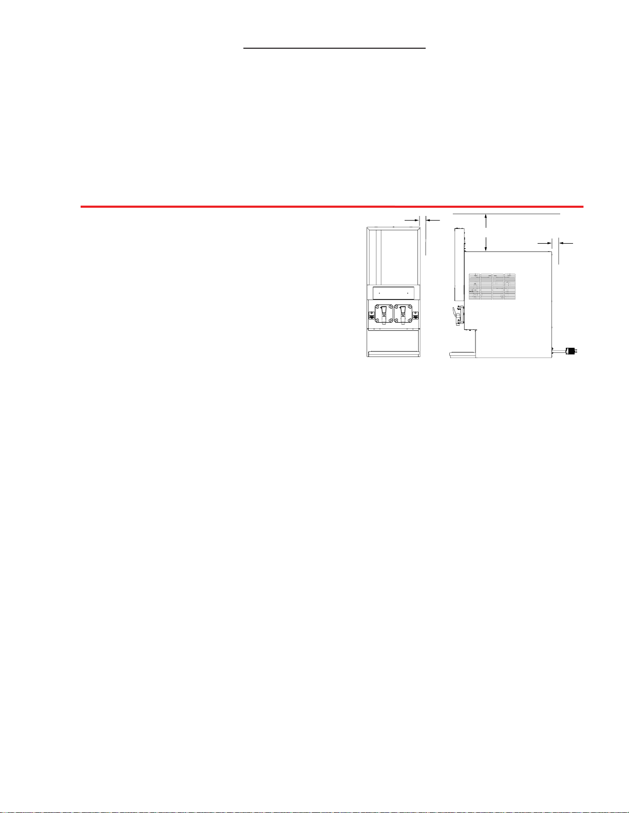
14.1 MOUNTING DIAGRAM - FBD562 ...................................................................................................42
6
1. Removal of side panels, if service is necessary.
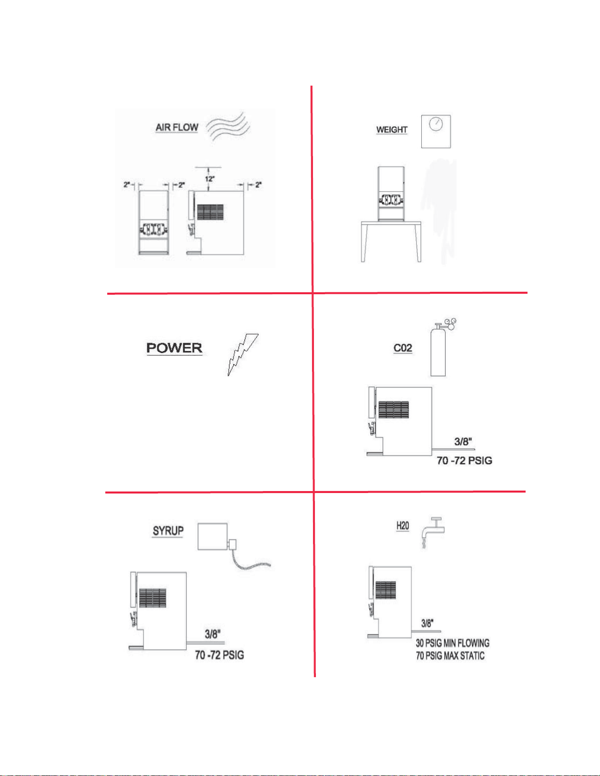
2. Air circulation around vents on sides, back, and top of unit.
C. A well-ventilated room is required with a temperature of 50°F to 90°F (10°C to 32.5°C). The
environment, however, should be stable and not subject to abrupt changes in temperature.
D. The unit should not be exposed to direct sunlight or chemicals.
1.2 ADDITIONAL REQUIREMENTS (TO BE PROVIDED BY THE CUSTOMER)
A. CO2 supply with a pressure of 70-72 psig ( 482.6 to 496.4 kPag). If a bulk CO2 supply is
used, the pressure should be set at 115 to 120 psig (792.9 to 827.4 kPag) and a secondary
regulator installed at the unit to reduce the pressure to 70-72 psig.
B. Syrup supply - Bag-in-Box or five (5) gallon syrup tank (figal).
C. Water supply with a minimum flowing pressure of 30 psig (206.8 kPag) and a maximum static
pressure of 70 psig (482.6 kPag).
2. RECEIVING AND UNPACKING UNIT
2.1 RECEIVING
Each unit is tested and thoroughly inspected before shipment. At the time of shipment, the carrier
accepts the unit and any claim for damages must be made with the carrier. Upon receiving the unit
from the delivering carrier, carefully inspect carton for visible indication of damage. If damage exists,
have carrier note same on bill of lading and file a claim with the carrier.
2.2 UNPACKING
A. Cut banding from shipping carton and remove carton by lifting up. Remove protective side
panels and four corner protectors.
B. Remove drip tray assembly, accessory kit and manual from top packaging. Contact the dealer if
any parts are missing or damaged.
C. Remove side panels from unit.
D. Inspect unit for concealed damage. If evident, immediately notify delivering carrier and file a claim
against same.
7
12 INCHES
2 INCHES
2 INCHES
Figure 1.1
(FBD562 Unit Displayed)
TABLE OF CONTENTS (CONTINUED)
14.2 MOUNTING DIAGRAM - FBD563 ...................................................................................................43
14.3 MOUNTING DIAGRAM - FBD564 ...................................................................................................44
14.4 FLOW DIAGRAM/SCHEMATIC - FBD562 ......................................................................................45
14.5 FLOW DIAGRAM/SCHEMATIC - FBD563 ......................................................................................46
14.6 FLOW DIAGRAM/SCHEMATIC - FBD564 ......................................................................................47
14.7 UPPER BOARD SCHEMATIC - FBD562 ........................................................................................48
14.8 LOWER BOARD SCHEMATIC - FBD562 .......................................................................................49
14.9 UPPER BOARD SCHEMATIC - FBD563 ........................................................................................50
14.10 LOWER BOARD SCHEMATIC - FBD563 .....................................................................................51
14.11 UPPER BOARD SCHEMATIC - FBD564 ......................................................................................52
14.12 LOWER BOARD SCHEMATIC - FBD564 .....................................................................................53
14.13 LOWER BOARD SCHEMATIC (INCLUDES AUXILIARY BOARD AND
DIO BOARD) - FBD564 ................................................................................................................54
1. PREPARING THE LOCATION
1.1 LOCATION REQUIREMENTS
A. The operational FBD56X countertop units
range in weight from 345 pounds (156.5
kg) to 460 pounds (208.7 kg) and each
unit requires a sturdy, level surface for
placement (see Safety Precautions, page 3).
When selecting a counter location, ensure
the counter will support the unit weight
plus the weight of any additional equipment
placed near it.
B. Adequate space above and behind a unit
(See Figure 1.1) is required to allow:
E. Lift unit up by the frame cross bracing and remove lower portion of carton.
F. If unit is received with a shipping board attached to the bottom, remove shipping board from bottom
of unit by accessing and removing the bolts located on the underside of the shipping board.
3. INSTALLING THE UNIT
There are several ways to install the unit. Follow the appropriate directions for the method you are using.
Ensure that there is a minimum of twelve (12) inches (30.48 cm) open space ABOVE and two (2)
inches (5.08 cm) open space on at least one side and BEHIND the unit (see Figure 1.1 above) for
proper ventilation.
3.1 FLUSH MOUNTING
Flush mounting is when the unit is mounted on a countertop. Follow the following guidelines to ensure
a proper installation.
A. Be sure the counter will support the weight of the specific FBD unit being installed and the full length of
the unit (including the drip tray). If permanently mounting the unit to a countertop, use the information in
Section 15.1 or 15.2 to mark and drill the four (4) mounting holes in the countertop.
B. Place unit on the counter using a lift (see Safety Precautions, page 3).
C. If permanently mounting the unit to a countertop, install four (4) 3/8-16 UNC bolts (not included)
through the underside of the counter [through the four (4) mounting holes drilled in the step just
above], and into the frame.
D. When the dispenser is to be permanently mounted to the counter top, seal dispenser base to counter
top with a bead of clear silicone caulk or sealant which provides a smooth and easily cleaned bond
to the counter.
3.2 ROLL AROUND CART
A roll around cart is used when a suitable countertop is not available and allows the unit to be moved for
cleaning. These can be purchased from the dealer.
A. Lock the wheels on the roll around cart.
B. Place the unit on the cart (see Safety Precautions, page 3).
C. Secure the unit to the cart by installing four (4) 3/8-16 UNC bolts (not included) through the cart
mounting holes and into the frame of the unit.
4. CONNECTING TO ELECTRICAL POWER
8
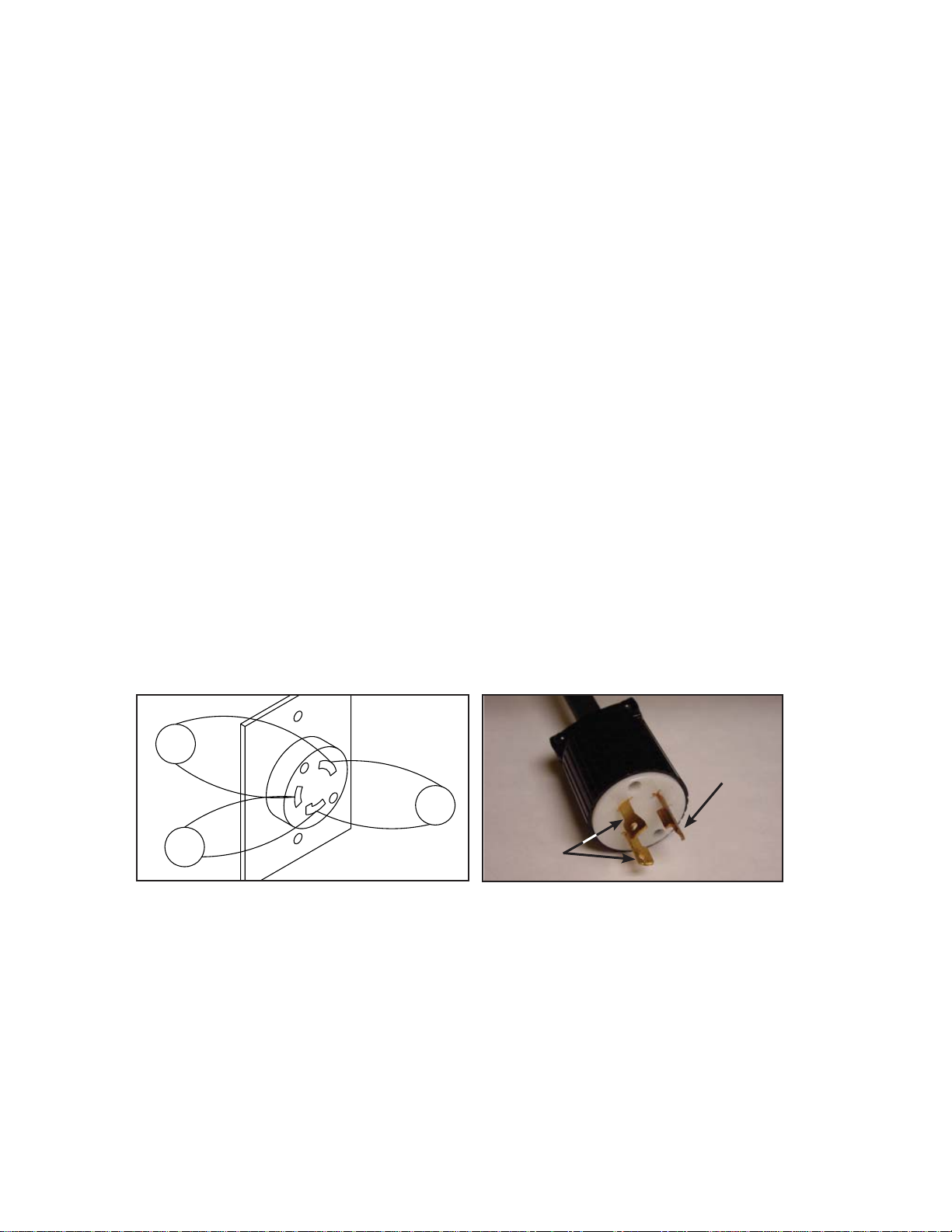
Figure 4.2
120V
240V
120V
Figure 4.1
Continuity
Ground
Use the following guidelines to connect electrical power to the machine for both 50 and 60 Hz service.
A. The machine requires single phase 230VAC. If line voltage is below 215VAC or above
245VAC, a 10% buck and boost transformer must be used. Operation below 215VAC or
above 245VAC may damage the unit and cause inconsistent performance. This also voids all
warranties.
B. If connected to a “delta” three phase electrical system, use the two low voltage legs (check each
leg to ground to insure the low voltage legs are used). Using the high voltage leg will cause the
machine to malfunction. In some locations, the power supply may have only one 230 volt hot leg.
If so, ensure the hot leg goes to the L1 contactor in the electrical box.
C. This unit will not work properly if there is more than a 10V voltage drop in the power supply line
between the power source and the machine. A drop of more than 10V indicates undersized wiring
or excessively long runs.
D. The unit must be installed on a “single branch” circuit (on a circuit by itself), installed as follows:
1. The FBD564 Unit must be protected by 30 Amp service and a 30 Amp fuse (or circuit breaker).
It is recommended that a 3 conductor, 30 Amp receptacle (NEMA #L630-R) be used. Using a
voltmeter, check voltage across both “hot legs” (240VAC) and between ground and each “hot
leg” (120VAC) to ensure proper wiring and voltage (see Figure 4.1).
2. The FBD562 and FBD563 Units must be protected by 20 Amp service and a 20 Amp fuse (or
circuit breaker). It is recommended that a 3 conductor, 20 Amp receptacle (NEMA #L620-R) be
used. Using a voltmeter, check voltage across both “hot legs” (240VAC) and between ground
and each “hot leg” (120VAC) to ensure proper wiring and voltage (see Figure 4.1).
E. Remove the plug from the power cord and feed the cord through the strain relief located at the back
of the unit. Tighten the strain relief securely. Reinstall the plug on the power cord and check for
continuity on the plug across both “hot legs” and no continuity between each “hot leg” and ground
(see Figure 4.2).
F. Do not connect the unit to power at this time.
5. CONNECTING WATER, CO
2, AND SYRUP SUPPLIES (SEE FIGURES 5.1 THROUGH 5.5)
5.1 WATER SUPPLY
IMPORTANT
A WATER PUMP AND WATER REGULATOR ARE
INSTALLED IN THE BASE OF THE MACHINE. A
WATER FILTER SHOULD BE INSTALLED IN THE
WATER LINE BEFORE BEING CONNECTED TO THE
MACHINE. FLUSH THE FILTER WITH SEVERAL
GALLONS (12-15 LITERS) OF WATER PRIOR TO
USE TO INSURE BLACK CARBON “FINES” ARE
NOT FED INTO THE FREEZING CHAMBER.
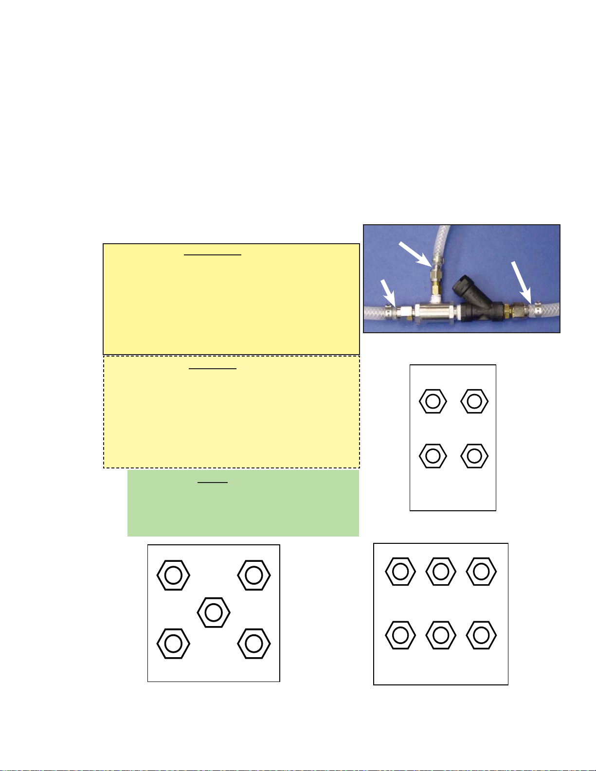
CAUTION:
THE BACKFLOW PREVENTION DEVICE (FBD PN
12-2272-0001) MUST HAVE A DRAIN LINE
CONNECTED TO THE VENT (SEE FIGURE 5.1).
THIS IS REQUIRED TO DRAIN AWAY WATER IN
THE EVENT OF A BACKFLOW SITUATION OR A
FAILURE OF THE BACKFLOW DEVICE. FAILURE
TO DO SO MAY RESULT IN FLOODING OF THE
ESTABLISHMENT.
NOTE:
Water pipe connections and fixtures directly
connected to a potable water supply shall be sized,
installed, and maintained in accordance with federal,
state and local codes.
Bulkhead Fittings, FBD562
Figure 5.2
DRAIN
WATER
SUPPLY
TO UNIT
Backflow Prevention - Water Connections
Figure 5.1
Bulkhead Fittings, FBD563
Figure 5.3
Bulkhead Fittings, FBD564
Figure 5.4
9
WATER
SYRUP
RIGHT
SYRUP
LEFT
CO2
24-0100-0011_B
SYRUP
RIGHT
SYRUP
LEFT
SYRUP
CENTER
WATERCO2
24-2012-0001_E
FLAVOR
#3
FLAVOR
#2
FLAVOR
#1
WATERCO2
FLAVOR
#4
24-2000-0001_C
AS VIEWED FROM FRONT

10
CONDENSER WATER
OUT
IN
Bulkhead Fittings, Condenser
Figure 5.5
A. Connect a backflow prevention assembly to the water inlet of the unit (see Figure 5.2). A backflow
prevention assembly is available from FBD under PN 12-2272-0001.
B. Fabricate a 3/8 inch supply line for connecting the unit to a potable water supply (a 3/8” barb by 1/4”
flare nut fitting will be required).
C. Install a shutoff valve in the water line as close to the unit as practical and convenient. The use of
a water filter is recommended.
D. Clear the line by running a minimum of two (2) gallons (7.57 liters) of water through the line before
attaching the line to the unit.
E. Connect the line to the bulkhead fitting labeled “WATER IN” located at the rear of the unit (see
Figures 5.2, 5.3 or 5.4, as appropriate).
F. For water cooled units:
1. Fabricate another water line from the main water line and
connect to the bulkhead fitting labeled “Condenser In” (a
3/8” barb by 3/8” flare nut fitting will be required) (see
Figure 5.5).
2. Fabricate a 3/8 inch drain line for connecting to the
location labeled “Condenser Out” (a 3/8” barb by 3/8” flare
nut fitting will be required) (see Figure 5.5).
G. Route the drain line to a drain location.
H. Do not turn water on at this time.
5.2 CO2 SUPPLY
NOTE:
The CO2 supply may come from either an independent tank/regulator or a bulk CO2 system. If
connected to a bulk CO2 system, install a shutoff valve and a secondary supply regulator [to be set at
70-72 psig (482.6-496.4 kPag)] in the line. Ensure that the CO2 line comes directly from the main
branch on the bulk supply and is not branched off down line. Failure to do so may starve the unit
of CO2 flow and cause performance problems.
A. Fabricate a 3/8 inch supply line for connecting the unit to a CO2 supply.
B. Connect the supply line to the CO2 bulkhead fitting labeled “CO2 IN” located at the rear of the unit
(see Figure 5.2). A 3/8” barb by 1/4” flare nut fitting will be required to make connection.
C. Splice a barb “cross” into the CO2 supply line and run two (2) lines to the syrup pump CO2 inlets.
Or
If Figal tank will be utilized, splice a barb “cross” into the CO2 supply line and run two (2) lines to tank
location and install CO2 tank couplers to end of lines.
D. Do not turn on the CO2 at this time.
5.3 SYRUP SUPPLY
The unit may be connected to either a BIB (Bag-in-Box) or a five-gallon syrup supply (figal). Use the
appropriate connection method below.
NOTE
Installations requiring long runs of tubing [25 feet or more (7.62 meters)] may encounter
pressure fluctuation problems. The machine’s sensors may indicate that the machine is out of syrup,
water, or CO2. To avoid pressure fluctuations, consider the following solutions.
A. Increase the tubing size to 1/2 inch diameter.
B. Install booster pumps in the supply lines. Use a vacuum regulating valve with syrup booster
pumps.
C. Increase primary CO2 regulator pressure from bulk or tank CO2 to 105 - 120 psig (723.9 to
827.4 kPag). A secondary regulator will be necessary for syrup pumps to avoid exceeding
manufacturer’s recommended operating pressures. Set the secondary regulator to 70-72 psig
(482.6-496.4 kPag).
BIB SUPPLY
A. Fabricate the appropriate number of 3/8 inch supply lines for connecting the unit to the syrup
pumps.
B. Connect the syrup lines to the bulkhead fittings as follows:
1. For the FBD562 Unit - to the appropriate bulkhead syrup fittings located at the rear of the unit
(see Figure 5.2).
2. For the FBD563 Unit - to the appropriate bulkhead syrup fittings located at the rear of the unit
(see Figure 5.3).
3. For the FBD564 Unit - to the appropriate bulkhead syrup fittings located at the rear of the unit
(see Figure 5.4).
C. Do not turn on the CO2 at this time.
FIVE GALLON (FIGAL) TANK SUPPLY
A. Fabricate the appropriate number of 3/8 inch supply lines for connecting the unit to the syrup
tanks.
B. Connect the syrup lines to the bulkhead fittings as follows:
1. For the FBD562 Unit - to bulkhead fittings labeled “SYRUP LEFT” and “SYRUP RIGHT” located
at the rear of the unit (see Figure 5.2).
2. For the FBD563 Unit - to bulkhead fittings labeled “SYRUP LEFT”, “SYRUP CENTER”, and
“SYRUP RIGHT” located at the rear of the unit (see Figure 5.3).
3. For the FBD564 Unit - to bulkhead fittings labeled “FLAVOR #1”, “FLAVOR #2”, “FLAVOR #3”,
and “FLAVOR #4” located at the rear of the unit (see Figure 5.4).
C. When using five gallon (figal) syrup tanks, a Syrup Restart Valve (SRV) and tank couplers
must be used on each line. Warranties will be void if an SRV is not installed.
1. The “OUT OF” devices in the machine will not function properly without the use of a Syrup
Restart Valve. If the “OUT OF” devices do not function, the machine will supply only water to
the product cylinder and it will freeze up.
2. When replacing a figal, insure that the syrup line to the dispenser is attached to the figal before
the CO2 line is attached to the figal. This will allow the SRV to work properly.
3. To operate the SRV, press the restart button
after syrup tank is changed. The red light
beside each chamber will then go out and
product will refreeze.
D. Do not turn on the CO2 at this time.
11
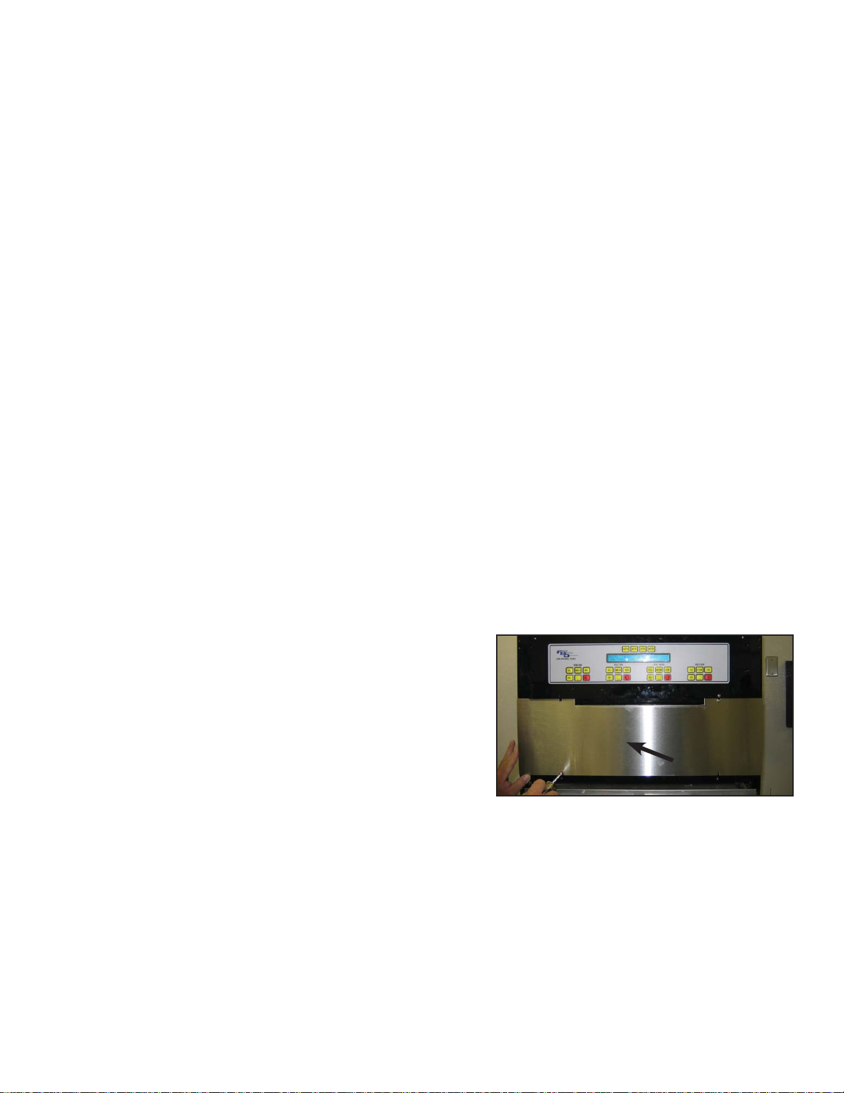
6. STARTING THE UNIT
6.1 INITIAL POWER-UP
A. Insure the electrical power is disconnected from
the unit.
B. Using a Phillips head screwdriver, remove the
stainless steel access panel located below the
keypad (see Figure 6.1).
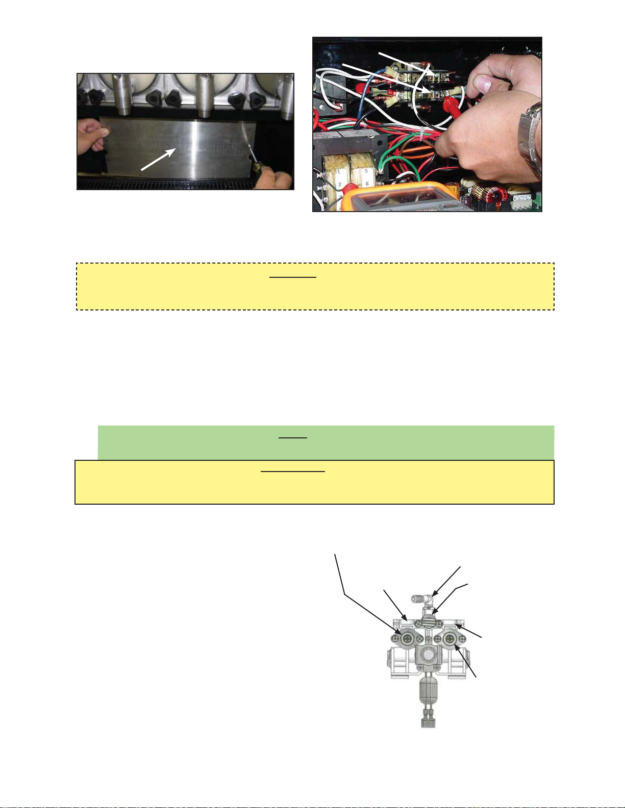
C. Remove the splash plate and electric box cover
(see Figure 6.2).
D. Plug unit in to the electrical power. The graphics display should illuminate. Check for the display of
information on the LCD control panel (this will read “COPYRIGHT” on bottom line of LCD display).
E. With voltage meter, check voltage at contactor between L1 & L2 and record (see Figure 6.3 and the
applicable Upper Board schematic in Section 14).
F. Access the “Line Voltage” readout in the “SERVICE MENU\READOUTS\COMMON
READOUTS” section of the LCD menu. If the “Readout” voltage is more than two (2) volts
different than the voltage across L1 and L2, the “Voltage Offset” must be changed.
Failure to do so will cause performance loss of the unit. To change the “voltage offset”, go to
“SERVICE MENU\MACHINE SETTINGS\COMMON SETTINGS” and enter the difference between
the meter reading and the “Line Voltage” readout to make the LCD voltage reading match the L1 and
L2 voltage. Reinstall the splash plate and electric box cover.
Access Panel
Typical Access Panel
Figure 6.1
6.2 BRIXING
A. With the unit powered up, press both of the “OFF” buttons on the display to ensure the unit is in the
OFF state.
CAUTION
CHECK ALL SUPPLY LINES TO ENSURE THAT THEY ARE CONNECTED TO THE CORRECT
FITTINGS. IF LINES ARE NOT CONNECTED PROPERLY, COMPONENTS WILL BE DAMAGED.
B. Open the water supply valve and check all water line connections for leaks.
C. Connect the BIB connectors, or the syrup and CO2 couplers, to figal tanks. Check all syrup supply
connections at the rear of the machine for leaks
D. Open the CO2 tank valve and adjust the primary tank regulator until the “CO2 Pressure” readout in
the “SERVICE MENU\ READOUTS\ COMMON READOUTS” reads 70-72 psig (482.6 kPag to 496.4
kPag). Check all CO2 line connections for leaks.
E. Adjust the CO2 secondary regulator (located inside the machine) to read 28-32 psig (193.1 to
220.6 kPag) according to the LCD readout found in the “REGULATED CO2” readout in the
“SERVICE MENU\ READOUTS\ COMMON READOUTS” section of the LCD menu.
NOTE
For low carbonation applications, see Quick Reference Sheet on page 4 for settings information.
IMPORTANT!
SET ALL PRESSURES USING THE LCD READOUTS ON THE UNIT - NOT BY THE GAUGES ON
THE REGULATORS!
F. Close Syrup flow controls by backing (turning counter-clockwise) the Right adjustment screw all the
way out (see Figure 6.4).
12
Electrical Box Cover
Typical Electrical Box Cover
Figure 6.2
L1
L2
Figure 6.3
Figure 6.4
FLOW CONTROL
ADJUSTMENT (WATER)
WATER PRESSURE
TRANSDUCER
SAMPLE VALVE OUTLET
STEM SHUTOFF
(TO OPEN SAMPLE
VALVE)
SYRUP PRESSURE
TRANSDUCER
FLOW CONTROL
ADJUSTMENT (SYRUP)
G. Open the sample valve and check
the water flow rate and set to provide a
flow of 15 ounces in 10 seconds using a
graduated container. Do this for every solution
module. Turn the Left adjustment
screw clockwise to increase flow or
counter-clock-wise to decrease flow.
H. Pre-set Syrup flow by turning Syrup flow
controls in three (3) turns (turning clock-
wise).
I. Place a container under the sample tube and
turn the sample valve until a good water and
syrup mixture is obtained (see Figure 6.4).
This sample should be discarded.
J. Place a sixteen (16) ounce (0.473 l) cup
under sample tube and open the sample
valve until 9 - 12 ounces (0.266 - 0.355 liter)
have been dispensed into cup.

13
K. Measure the brix with a refractometer. Set brix to between 13.5 and 15.0 by adjusting the syrup
brix flow controller clockwise to increase brix level or counter-clockwise to decrease brix level. If
the brix requires adjustment, discard a sample before checking the brix again.
NOTE
Do not adjust the brix with the water flow control setting unless you are unable to obtain the desired
brix with adjustments to the syrup flow control.
Brix reading is affected by temperature. Samples taken from the chamber should be at the same
temperature as from the sample valve.
L. Repeat steps I, J, and K for other chambers.
6.3 FILLING THE CHAMBER
A. Access “CO
2 SOL” by going to the “SERVICE MENU\MANUAL ON/OFF” section of the service
menu.
B. Displace the air in the chamber with CO2 by activating the CO2 solenoid.
1. Pull and hold the relief ring until the escaping, rushing air sound almost stops; then release the
ring. Allow the pressure to rebuild in the tank.
2. Repeat this procedure at least two more times until the air has been displaced by the CO2.
Remember to deactivate the CO2 solenoid upon completion.
C. Repeat steps A and B above for the other chambers. Remember to deactivate the CO2 solenoid
upon completion.
D. With CO2 in the chamber, press a “FILL” button to begin filling the chamber with product. If the
chamber does not fill, gently pull the Relief Ring until filling begins and then release. As the cham-
ber fills, the pressure in the chamber will increase until it rises above the psi fill point. At this point,
the chamber will stop filling and the LCD will readout “Fill Hold”. It will then be necessary to pull
the relief ring to relieve the pressure and allow filling to continue. Slowly pull the relief ring until the
pumps activate, then release. Repeat the venting process until the chamber is 90% full (level
with relief valve), then press Fill button to turn OFF. Fill one (1) chamber at a time.
E. Repeat steps A, B, C, and D for the remaining chambers.
F. Press the “DEFROST” and then the “RUN” buttons on both sides of the control panel to begin
the freezing process. The beater motors will begin to run but the compressor will wait for
two (2) minutes before starting. After the two (2) minute waiting period, the machine will defrost
and then begin the freeze cycle.
G. After an initial freeze down, the product will be frozen and ready to dispense.
NOTE
On an initial freeze down, products must be given adequate time to absorb CO2. Until CO2 is
properly and adequately absorbed, drinks could be too “wet” or too “heavy”. If adjustments are
necessary, refer to section 9.
H. Re-check CO
2, Water, and Syrup lines for leaks.
14
FBD
FWDBACK SELECTCANCEL
OFF
RIGHT SIDE
FILL BEATER
RUN
DEF.
LEFT SIDE
FILL BEATER
RUN
OFFDEF.
CENTER
FILL BEATER
RUN
OFFDEF.
CRITICAL REGULATOR AND FLOW CONTROL SETTINGS
SET ALL PRESSURES USING THE LCD READOUTS ON THE UNIT - NOT BY THE GAUGES ON THE
REGULATORS!
CO
2 PRIMARY REGULATOR The CO2 Primary Regulator MUST BE SET TO 70-72 psig
(482.6 TO 496.4 kPag).
CO2 SECONDARY REGULATOR The CO2 Secondary Regulator SHOULD BE SET AT 28-32 psig
(Secondary Regulator) (193.1 TO 220.6 kPag) STATIC PRESSURE.
For low carbonation applications, see Quick Reference Sheet on
page 4 for settings information. The CO2 Secondary Regulator is
on the header assembly which is behind the access panel. This
regulator is a “non-vent” regulator. This means that if you lower
the regulator setting, you will need to dispense drinks (with “Fill”
activated) until cylinder begins to refill before the new setting will
register on the gauge.
FLOW CONTROLLERS WATER FLOW MUST BE SET TO PROVIDE A FLOW OF
15 OUNCES IN 10 SECONDS BEFORE ADJUSTING THE BRIX.
BRIX MUST BE SET BETWEEN 13.5 - 15. Flow controllers are on
the header assembly. A sample may be taken by fully opening the
sample valve, by turning it clockwise until it stops.
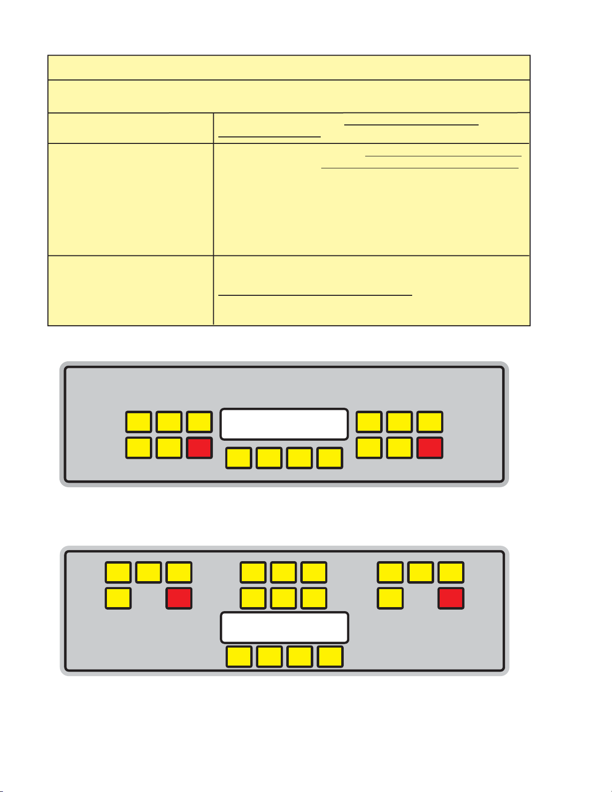
FBD563 Contols
Figure 7.1b
FBD
FWDBACK SELECTCANCEL
OFF
RIGHT SIDE
FILL BEATER
RUN
DEF.
LEFT SIDE
FILL BEATER
RUN
OFFDEF.
FBD562 Contols
Figure 7.1a
15
SAN ANTONIO, TEXAS
SIDE ONE
SIDE TWO SIDE THREE
SIDE FOUR
FILL
BEATER
RUN
DEF.
OFF
FILL
BEATER
RUN
DEF.
OFF
FILL
BEATER
RUN
DEF.
OFF
FILL
BEATER
RUN
DEF.
OFF
CANCEL
SELECT
BACK
FWD
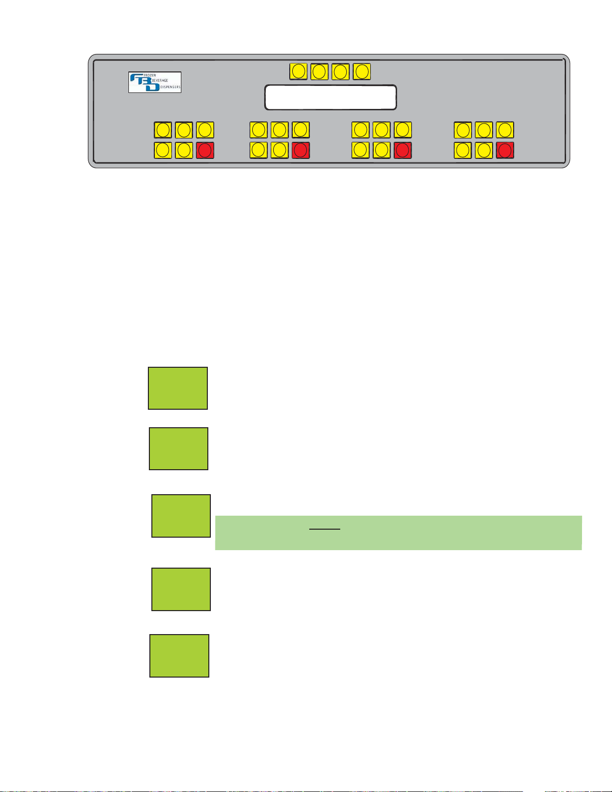
FBD564 Contols
Figure 7.1c
7. OPERATION OF THE DISPENSER
7.1 OPERATING ELECTRONIC CONTROLS
A. The electronic machine controls are designed to provide a logical sequence of operation with a
minimum of written instruction. System operating parameters are selected and set from a menu.
B. Buttons (see Figures 7.1a, 7.1b and 7.1c).
1. Each chamber has five (5) active buttons. They are labeled FILL, BEATER, RUN, DEF (defrost),
and OFF.
2. Each button operates a double acting switch. Pressing the button once activates the
process. Pressing the button a second time deactivates the process. Take care not to double
press the buttons when first activating a process.
The RUN button initiates the freeze process. After pressing this button, the
beater motors will run for five (5) seconds before the compressor starts. Run also
maintains the flow of product into the chambers when needed. You should always
press the DEFROST button first to baseline the unit.
The OFF button turns off all the machine’s refrigeration and chamber refill
systems. All of the electronic controls are still active.
The BEATER button activates the beaters inside the freezing chambers. The
beaters can be activated to mix the slurry.
NOTE:
The beaters start automatically when the RUN or DEF buttons are pressed.
The DEF button allows the user to manually defrost chamber. Because
the unit automatically defrosts during the day, it is not necessary to defrost
manually. However, this button provides the option to do so if desired.
The FILL button activates the solenoid valves that allow product to flow into the
freezing chambers (providing the pressure in the barrel is low enough to allow a
fill). Each chamber should be filled to 90% of chamber capacity (level with the
relief vent valves) prior to start-up.
RUN
OFF
BEATER
DEF
FILL

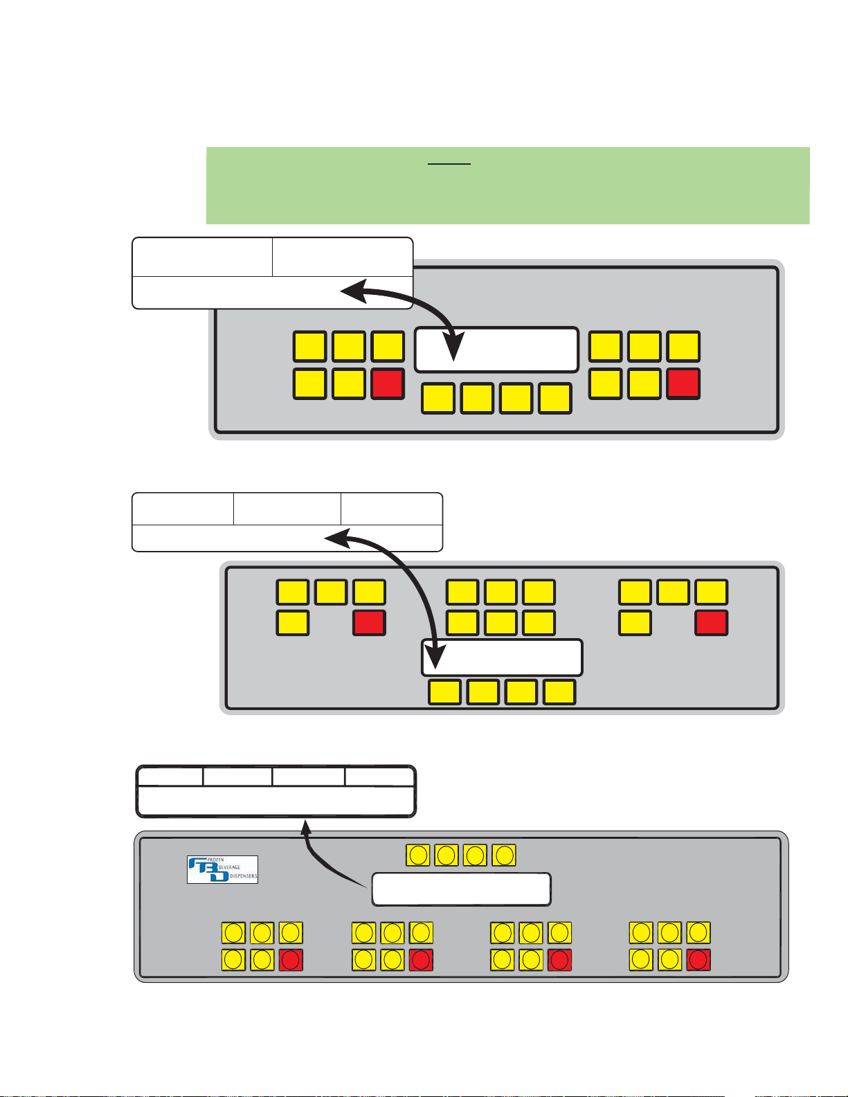
C. Common Controls and Displays
1. The four (4) control buttons, located below the LCD display, allow access to the various menu
levels for the machine (see Figures 7.1a, 7.1b and 7.1c)
The CANCEL button cancels any current operation and steps the operator back
one (1) level in the menu.
The BACK button steps the operator backwards within the current level. This
button also allows the operator to decrease or lower values (numbers).
The FWD button steps the operator forward within the current level. This button
also allows the operator to increase or raise values.
The SELECT button allows the operator to enter changes in the unit programming
and it also allows the operator to move into different levels in the menu.
2. The LCD display screen in the center of the control panel allows the operator access to unit
status, settings, and operational information (see Figures 7.2a, 7.2b and 7.2c). The screen is
divided into an upper and lower section. The upper section of the screen will show the current
status of each chamber. The lower half of the screen displays a mode that can be changed or
monitored.
D. Explanation of the Menu Structure (See Figure 7.3)
1. Access to the control panel is separated into two (2) levels. These levels have been established
to make certain information available to the operators and other information available to service
personnel.
Level One This CUSTOMER MENU level is designed for the machine operator at the store
level. The store operator should only access this level of information, and should
NOT access or make changes in the SERVICE MENU without prior authorization
and approval.
Level Two The SERVICE MENU has been established for the use of authorized service
technicians ONLY. This level provides access to all setup values that will optimize
the operation of the machine. Incorrect settings at this level could prevent the
machine from operating properly or cause damage to the unit. Included in this
level are various accumulated totals and diagnostic tools that help the technician
evaluate problems.
NOTE
To access the Service Menu, press the FWD button on the control panel until “SERVICE MENU”
displays. Press the unmarked button on the Left side of the panel (center blank button for the
563). The service menu has been accessed when “MACHINE SETTINGS” displays. Press
FWD to access other options.
E. How to Access and Change Values
The same procedure for changing values applies to all access levels. The following steps allow the
parameters of the control system to be monitored and changed.
1. The current mode is displayed in the lower half of the LCD. Press the FWD button to step
to the next mode. Continue pressing the FWD or BACK button until the desired mode is
displayed. When the desired mode is displayed, press SELECT to enter the mode.
2. To make changes to the displayed mode, press the SELECT button. When a value in the lower
half of the display begins to flash, this indicates that the value can be changed.
CANCEL
BACK
FWD
SELECT
16
17
3. To change the value, press the FWD button to increase the value or the BACK button to decrease
the value. Any on/off functions can be changed by pressing the SELECT button.
4. Once the desired value is displayed, press the SELECT button to enter the value into the
computer. Pressing the SELECT button will stop the display from flashing. When the value
stops flashing, it has been changed.
NOTE:
When entering TIME, WAKE, or SLEEP functions, both the hours and minutes must be
selected before the computer will accept the change. For the Defrost Times, days in upper case
(capitals) are selected. Days in lower case are NOT selected.
FBD
FWDBACK SELECTCANCEL
RIGHT SIDE
FILL BEATER
RUN
DEF.
LEFT SIDE
FILL BEATER
RUN
DEF.
CENTER
FILL BEATER
RUN
OFFDEF.
SIDE 1 STATUS
MODE DISPLAY
SIDE 2 STATUSCENTER STATUS
OFF
OFF
FBD563, Access and Change
Figure 7.2b
FBD
FWDBACK SELECTCANCEL
RIGHT SIDE
FILL BEATER
RUN
DEF.
LEFT SIDE
FILL BEATER
RUN
DEF.
SIDE 1 STATUS
MODE DISPLAY
SIDE 2 STATUS
OFF
OFF
FBD562, Access and Change
Figure 7.2a
SAN ANTONIO, TEXAS
SIDE ONE
SIDE TWO SIDE THREE
SIDE FOUR
MODE DISPLAY
SIDE 2 STATUS
SIDE 1 STATUS
SIDE 4 STATUS
SIDE 3 STATUS
FILL
BEATER
RUN
DEF.
OFF
CANCEL
SELECT
BACK
FWD
FILL
BEATER
RUN
DEF.
OFF
FILL
BEATER
RUN
DEF.
OFF
FILL
BEATER
RUN
DEF.
OFF
FBD564, Access and Change
Figure 7.2c
 Loading...