

Page 1
®
MIDICONTROLLERS
INDICE
• Caratteristiche generali 3
• Connessioni 3
• Pannello comandi 4
• Programmazione 4
• Edit 5
• MIDI Channel 5
• Bank Select 5
• Program Change 5
• Split 5
• Transpose 5
• Sustain 6
• Wheels 6
• Aftertouch 6
• Shape 6
• Velocity 7
• Utilizzazioni MIDI 7
• Reset generale 7
•Varie tabelle 7
ITALIANO
CARATTERISTICHE
GENERALI
CONNESSIONI
envenuti nel mondo delle Studiologic Midicontrollers. La midicontroller SL-161/SL-61 è un
MIDI Controller professionale con un software non sofisticato ma che soddisfa le esigenze del
musicista che vuol lavorare in studio o in situazione live.
B
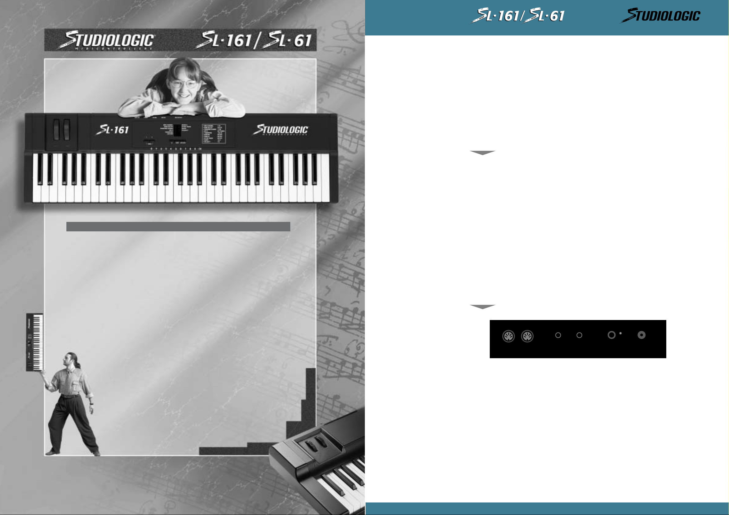
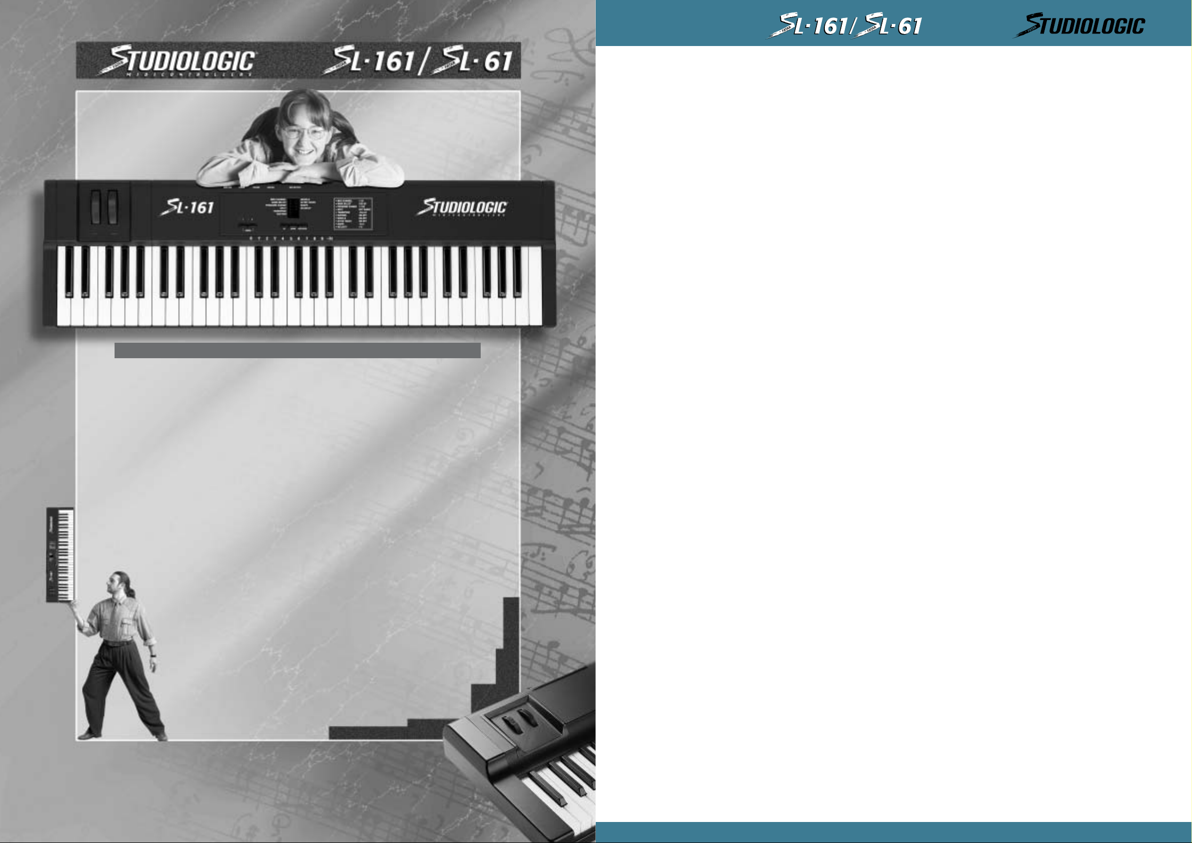
La midicontroller SL-161/SL-61 si presenta con:
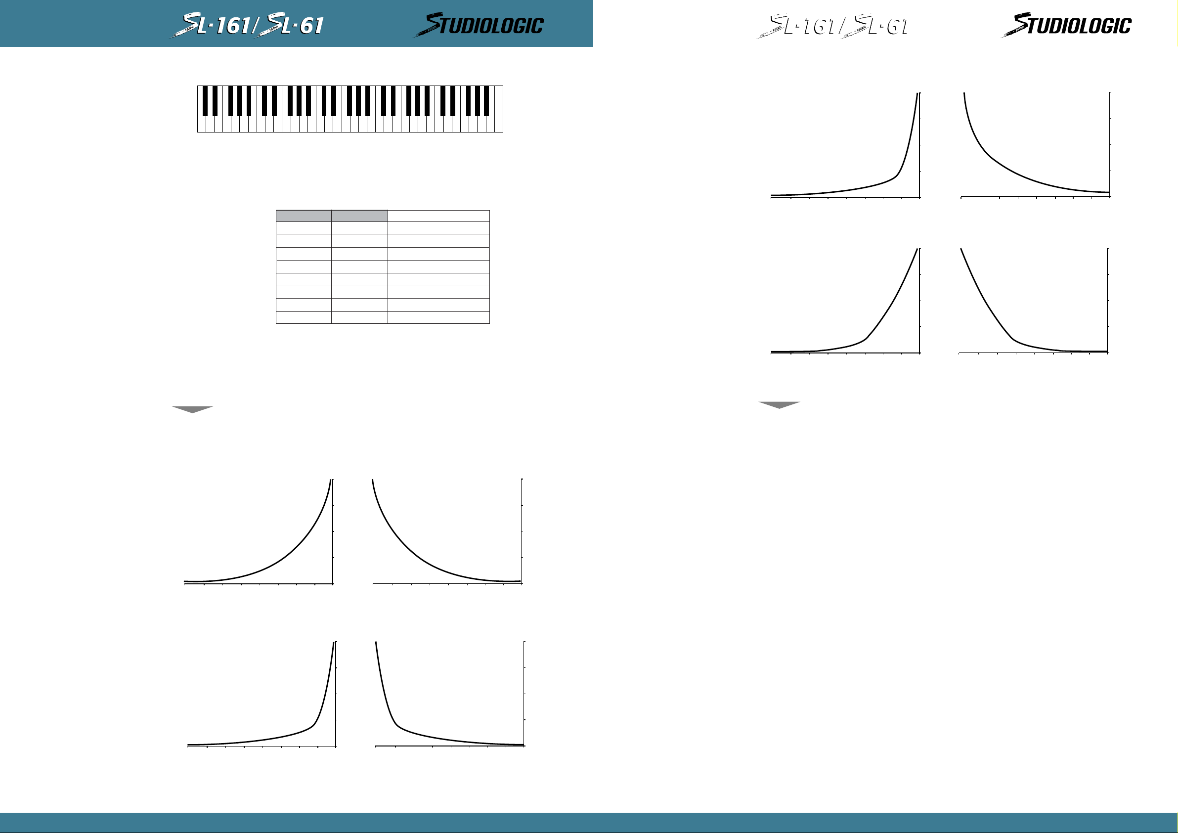
• Tastiera dinamica a 61 tasti non pesati tipo Synth.
• After touch.
• 2 ruote di modulazione di cui una Pitch bender e l’altra Modulation.
• Pannello di controllo con 5 tastini di cui 2 per abilitare o disabilitare le zone di tastiera, un
tastino di Enter/Edit, 2 tastini per lo scroll (up/down) dei parametri in ambiente Edit, 10
leds per segnalare il parametro su cui si interviene, 2 leds posti sopra i tastini di zona per
indicare il loro stato di attività (on - off).
• 2 zone di tastiera per splits o layers programmabili.
• Tastierina numerico-funzionale posizionata sull’ottava centrale della tastiera.
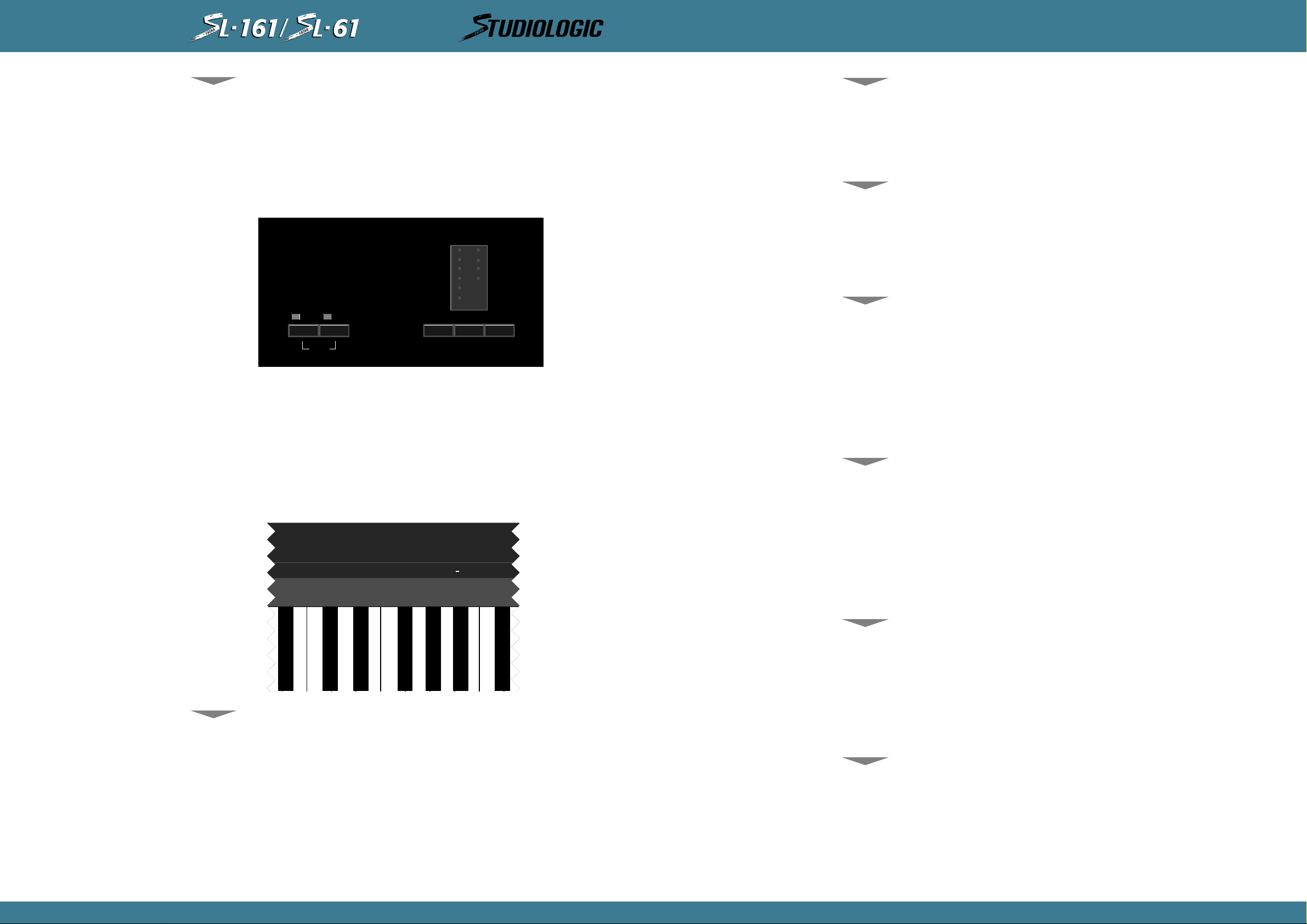
• Pannello posteriore con: 2 uscite MIDI parallele, 1 jack input per il Sustain, 1 jack per il
Vol u m e generale, l’ingresso di alimentazione DC, l’interruttore di alimentazione e il relativo led di
segnalazione .
• 1 locazione di memoria per storare l’ultima programmazione eseguita su tutti i parametri di
tutte le zone sulle quali si é lavorato.Alla riaccensione la macchina ripresenta l’ultima programmazione e l’ultima situazione di zone attivate.
MIDI OUTPUTS
1
1) Collegare l’adattatore di tensione alla presa elettrica di rete (verificando che la tensione dell’adat-
tatore corrisponda alla tensione di linea.) Collegare il cavo d’uscita dell’adattatore all’ingresso di alimentazione della Midicontroller (la SL-161/SL-61 accetta come alimentazione
9VDC con polarità positiva + al centro (in caso contr ari o non si accende) e necessita di una
corrente minima di 200 mA).
2) Collegare il/i cavi MIDI al vostro o ai vostri expander o altri dispositivi MIDI.
3) Se si ha la necessità di controllare il sustain o il volume, collegare agli appositi jacks,
per il volume un pedale di controllo lineare con jack stereo (es:VP26), per il sustain un
qualsiasi pedale con il contatto o normalmente aperto o normalmente chiuso dato che se
il pedale è collegato alla Midicontroller quando si accende, viene riconosciuto automaticamente il tipo di contatto usato. (es: PS100/VFP1)
4) Attivare la Midicontroller SL-161/SL-61 premendo il pulsante sul retro. Ora si predisporrà
sull’ultima situazione di lavoro prima dello spegnimento riguardante le zone attive e tutti i
parametri programmati in precedenza.
2
SUSTAIN VOLUME
POWER
9V DC 0,2 A
3
MANUALE D’ISTRUZIONI
Page 2
®
MIDICONTROLLERS
®
MIDICONTROLLERS
ITALIANO
024579
/H
1
ON
3
OFF
86
ITALIANO
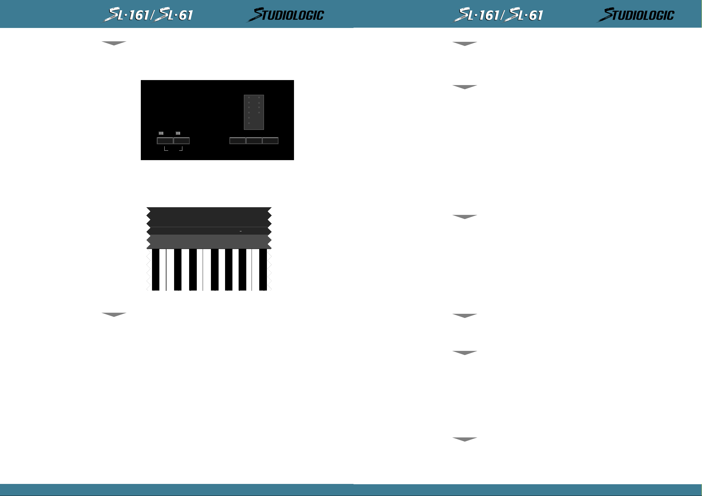
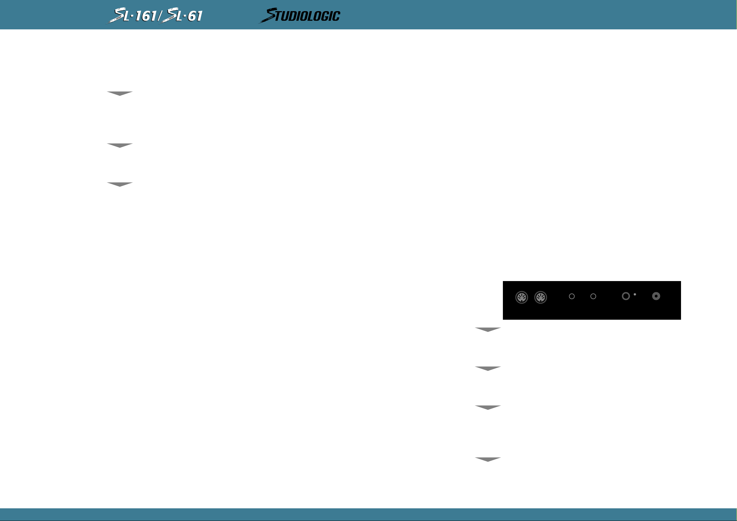
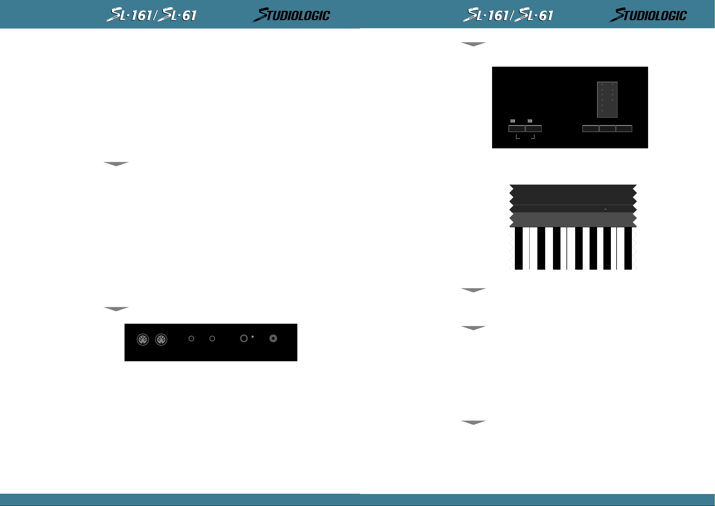
PANNELLO COMANDI
Il pannello comandi della parte superiore della tastiera si presenta come mostrato in figura,
con 10 led e la relativa serigrafia del parametro di programmazione,i 2 tastini di zona con
relativo led indicante l’ attivazione, il tastino di enter/edit e i2 tastini di up/down per posizionarsi con il led sul parametro voluto.
WHEELS
AFTER TOUCH
SHAPE
VELOCITY
12
ZONES
MIDI CHANNEL
BANK SELECT
PROGRAM CHANGE
SPLIT
TRANSPOSE
SUSTAIN
UP DOWN ENTER/EDIT
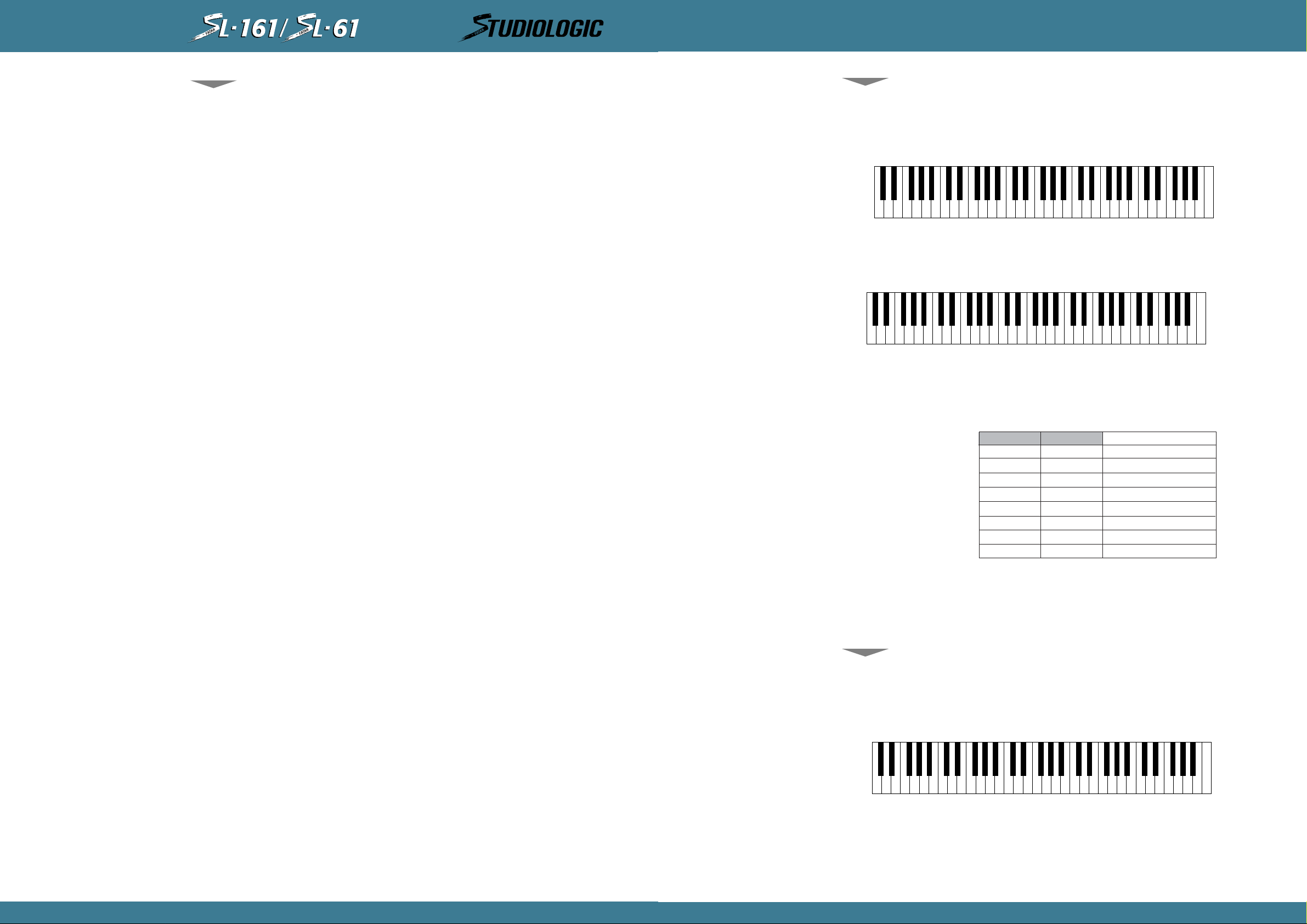
Per assegnare i valori o gli stati dei parametri, si userà la tastierina numerico-funzionale
posizionata sull’ottava centrale della tastiera; a partire dal do centrale avremo i caratteri a
disposizione come segue:
EDIT
Per entrare in Edit peremere il tastino “Enter/Edit”, si accenderà il primo led rosso in alto a
sinistra e il Led della zona n°1.
Se si vogliono editare i parametri della zona n°1 si può procedere, altrimenti premere il tastino della zona interessata.
MIDI CHANNEL
Il primo parametr o é con trassegnato MIDI CHANNEL, quindi se si vuole cambiare il n° di canale MIDI basta premere il tasto relativo al numero voluto sulla tastierina numerica.
ATTENZIONE! Dato che nella programmazione di Default i canali assegnati sono rispettivamente 1,2 e dato che in due zon e differen ti non si può assegn are lo stesso n umer o di canale MIDI,
il software non accetta il numero di canale se questo é presente in un’altra zona; quindi per
farlo accettare si deve rimuovere dalla zona quel numero di canale MIDI non più voluto.
N.B. Ogni comando di Edit e variazione di sistema viene trasmesso in uscita MIDI o uscendo
dall’Edit o premendo il tastino di zona interessato o passando ad un altro parametro mediante i tastini Up / Down.
Quando si é in ambiente Edit, si ha la libertà di muoversi tra i vari parametri e tra le diverse
zone facend o attenzione a quale Led di zona é attivato. Quindi si é liberi di programmare una
zona per volta uscendo dall’Edit, oppure eseguire una programmazione globale di tutte e due
le zone.
Ora procediam o con la pr ogramm azi on e di altri par am etri concen tr an d oci su un a zona d ato ch e
la procedura é poi ripetitiva per le altre
CARATTERISTICHE
GENERALI
La midicontroller SL-161/SL-61 alla prima accensione si predisporrà in una programmazione di
default che descriviamo qui di seguito:
Zona attiva n°1 - zona 2 in off - le due zone trasmettono rispettivamente la n°1 sul canale
midi n°1, la n°2 sul canale midi n°2.
Le zone hanno un’estensione completa a 61 tasti, i controlli tutti in stato on, curve di dinamica n°1, transpose = 0.
Per disattivare una zona ed attivarne un’altra, ricordarsi che no si deve premere alcun tasto
della tastiera e non di deve avere il pedale sustain premuto.
LE OPERAZIONI VANNO ESEGUITE IN SEQUENZA: se ad esempio si vuol disattivare la zona 1 ed
attivare la zona 2, premere il tastino zona n°1 ed il suo Led si spegnerà, poi premere il tastino zona n°2 ed il suo Led si accenderà.
N.B. se in questo mom ento si spegn erà lo strum en to, alla sua ri accen si one si ved rà la zon a n°2
attiva in quanto il softwar e preved e di mem orizzare le pr ogr ammazi oni dei par am etri delle zon e
e quali sono le zone attive al momento dello spegnimento.
Prima di procedere con la spiegazione della programmazione, ricordare che se si hanno tasti
premuti sulla tastiera od é premuto il pedale sustain, non si possono attivare o disattivare le
zone come non si può en trare in Edit; viceversa quando si é in Edit la tastiera non suona dato
che è abilitata la tastierina numerica per assegnare valori e stati ai parametri di programmazione delle zone.
BANK SELECT
Dopo aver assegnato il MIDI CHANNEL se si preme il tastino Down si passa al parametro BANK
SELECT che serve per commutare il gruppo o banco di suoni dell’expander o tastiera MIDI.
Il protocollo di ricezione di questo comando si differisce a seconda del tipo o marca di modulo MIDI che si usa:
Se il modulo richiede come Bank Change solamente il Control 32, basta digitare sulla tastierina il nu mero di banco desiderato.
Alcuni moduli richi ed ono per comm utar e il Ban co di su oni un pr otocollo più completo (Con trol
32 + Contro 0). Quindi se si richiede la stringa completa di Control 32 più Control 0, digitare
prima il numero per il Control 32 poi premere il tasto contrassegnato con H che sta a significare la parte alta del Byte della stringa di Bank Change e digitare il numero voluto per il
Control 0.
Fatto ciò il comando di BANK SELECT per quella zona é completo (Sequenza esplicativa: digitare il numero per il C32, premere il segno (-) e digitare il numero per il C0).
PROGRAM CHANGE
Premendo ancora il tastino Down passiamo alla programmazione del PROGRAM CHANGE il cui
valore numerico corrisponde al numero di suono del modulo MIDI. Digitare il numero voluto
sulla tastierina (i numeri accettati sono da 1 a 128).
SPLIT
Premendo ancora il tastino Down passiamo alla programmazione degli Splits cioé si determina
per la zona interessata l’esten sion e di tastiera attiva U na volta d eterminata la zon a sulla quale
si vuole eseguire lo Spit é suffici ente prem ere con le dita sulla tasti era i due tasti ch e delimitan o lo Split
voluto. La p r ogr amm a zio n e di De f ault prevede per tutte le 2 zone una estensione completa ad
61 tasti. Ad esempio se si vuole che la zona n°2 suoni solamente dal Do centrale verso l’alto, quando si é in Edit ed é acceso il Led r osso in corrispondenza della dicitura SPLIT, si dovrà
premere il tastino Zona n°2 e a questo punto si premeranno sulla tastiera il Do centrale e poi
il Do finale.Uscendo dall’Edit ora la Zona n°2 sarà attiva nel modo voluto e qusto settaggio
rimarrà in memoria (come del resto i valori degli altri parametri).
Se si hanno chiari i punti di Split delle due Zone quando si é in Edit si possono programmare
tutti gli Split agendo su una Zona alla volta.
TRANSPOSE
Premendo ancora il tastino Down passiamo alla programmazione del Transpose se necessario.
In condizioni norm ali le 2 Zon e hanno il valor e di tran spose = 0 cioé il Do cen tr ale della tasti e-
4
5
MANUALE D’ISTRUZIONI
MANUALE D’ISTRUZIONI
Page 3
®
MIDICONTROLLERS
®
MIDICONTROLLERS
ITALIANO
ITALIANO
SUSTAIN
WHEELS
AFTER TOUCH
SHAPE
ra corrisponde al Do centrale della chiave musicale di Do. Se per una Zona si vuole innalzare
l’intonazione di 4 semitoni, quando si é posizionati con il Led nella sezione Transpose basta
digitare per la zona interessata il numero 4 sulla tastierina numerica; Se come altro esempio
si vuole abbassare l’intonazione di una ottava si dovrà prima premere il tasto nero (Slb) etichettato con - e poi digitare il numero 12.
Riassumendo: Per effettuare Transpose positivi digitare il numero di semitoni voluti. Per effettuare Transpose negativi digitare prima il segno meno ( - ) poi il numero dei semitoni voluti.
N.B.: La SL-161/SL-61 accetta come numero massimo +/-24 semitoni quindi +/-2 ottave.
Premendo ancora il tastino Down passiamo alla programmazione del Sustain se necessario.
Per programmazione si intende la possibilità di memorizzare per ogni zona l’abilitazione o la
disabilitazione del ped ale Sustain. Ad esempio se n ella Zon a n°2 si ha la necessità di n on vedere che il pedale Sustain abbia effetto, quando si é posizionati con il Led nella sezione Sustain
si premerà il tastino di Zona n°2, poi si digiterà il comando OFF che corrisponde alla nota Mlb
della tastierina numerico-funzionale. A questo punto l’altra Zona subirà l’effetto del pedale
Sustain mentre n ella Zon a n°2 n on avrà effetto. Se si vorrà ripristinare il con tr ollo in quella Zon a
basterà rientrare in Edit e digitare il controllo ON.
Premendo ancora il tastino Down passiamo alla programmazione delle Wheels se necessario.
Per programmazione si intende la possibilità di memorizzare per ogni zona l’abilitazione o la
disabilitazione delle 2 ruote di modulazione. Ad esempio se nella Zona n°2 si ha la necessità
di non volere che le Wheels abbiano effetto, quando si é posizionati con il Led nella sezione
Wheels si premerà il tastino di Zona n°2, poi si digiterà il comando OFF che corrispondealla
nota Mlb della tastierin a num erico-funzi onale . A questo pun to l’altra Zon a subirà l’effetto delle
due ruote di modulazione mentre nella Zona n°2 non avranno effetto. Se si vorrà ripristinare
il controllo in quella Zona basterà rientrare in Edit e digitare il controllo ON.
Premend o ancora il tastino Down passiamo alla programmazione dell’After Touch se necessari o.
Per programmazione si intende la possibilità di memorizzare per ogni zona l’abilitazione o la
disabilitazione dell’After Touch. Ad esempio se nella Zona n°2 si ha la necessità di non volere
che l’After Touch abbia effetto, quando si é posizionati con il Led nella sezione After T. si premerà il tastino di Zona n°2, poi si digiterà il comando OFF che corrisponde alla nota Mlb della
tastierina num eri co-funzi on ale. A questo punto l’altra Zona subirà l’effetto di After Tou ch m entre nella Zona n°2 non avranno effetto. Se si vorrà ripristinare il controllo in quella Zona basterà
rientrar e in Edit e digitare il controllo ON.
Premendo ancora il tastino Down passiamo alla programmazione delle Shape, cioè delle curve
di dinamica. Se si vuole adattare la propria midicontroller alla risposta dinamica dell’expander o dispositivo MIDI o se si vuole adattar e il prim o tocco alla risposta di tasti er a n el mi gli or
modo, la SL-161/SL-61 nel parametro Shape o ffr e 4 tipi di curve diverse le quali possono essere memorizzate come per gli altri parametri. Per ogni zona posso assegnare un tipo di Shape
differente se necessario.
La SHAPE N°1 ha una risposta lineare ed abbastanza rispondente alla maggioranza di dispositivi MIDI in commercio.
La SHAPE N°2 ha una risposta m eno sen sibile quindi si dovrà su onar e con un poco più di forza;
in alcuni casi si può definire più espressiva; può essere utile usarla se il dispositivo MIDI in
ricezione é troppo sensibile.
La SHAPE N°3 ha una risposta più sensibile della Shape n°1 e potrebbe essere usata se il
dispositivo MIDI in ricezione é poco sensibile o per alcuni suoni particolari.
La SHAPE N°4 ha una risposta ancora più sensibile della Shape n°3.
La Midicontroller SL-161/SL-61 possiede 4 Shape positive e 4 Shape negative per un totale di
8.Per assegnare una Shape n egativa prima di digitar e il numer o desid erato si d ovrà digitare il segn o meno
(-). Per Shape negativa si intende che la curva risponde in modo contrario al tocco cioé se si
suonerà piano la dinamica risponderà a livelli alti, se si suonerà forte la dinamica risponderà a
livelli bassi.
Questa possibilità può essere sfruttata programmando due zone con curve di dinamica una
positiva e una negativa per ottenere un crossfade o incrocio di suoni mediante il controllo della dinamica. La Shape -1 corrisponde alla Shape 1 invertita e così via per le altre.
VELOCITY
Premendo ancora il tastino Down passiamo alla programmazione della Velocity.
Questo parametro é globale e quindi non individuale per ogni singola zona; infatti passando
a questo ultimo parametro si vedranno accendere tutti e 2 i Led delle Zone.
Mentre nel parametro precedente si d efiniscon o per ogni sing ola Zon a le curve di risposta d inamica, in questo parametr o globale si possono scegliere 8 sensibilità di risposta alla velocità del tocco.
Anche questo parametro aiuta il musicista ad adattare la propria tastiera al modulo MIDI nel
miglior modo possibile per rendere più espressivo e controllabile il proprio modo di suonare.
Ora dopo aver agito su tutti i parametri che interessano nella programmazione per uscire dall’ambiente Edit basta premere il tasto contrassegnato con “Enter/Edit”.
UTILIZZAZIONI MIDI
Ricordiamo le principali funzionalità della Midicontroller: accendo lo strumento, dopo qualche
secondo è pron to a trasmettere dati MIDI voluti e saranno attive le Zone che erano state abilitate prima dello spegnimento.
Quando si entra in EDIT la tastiera non suona dato che i tasti dell’ottava centrale sono abilitati per digitare numeri e controllidi programmazione.
Per verificare le varazioni eseguite in programmazione si dovrà uscire da EDIT, si spegnerà il
Led del parametro programmato e la tastiera sarà di nuovo pronta a suonare con la variazione eseguita e memorizzata.
Quando si entra in EDIT per la prima volta dopo l’accensione, il Led acceso sarà il primo cioè
Midi Channel; se il parametro voluto sarà un’ altro ci si dovrà spostare con i tastini di Scroll
cioè UP o DOWN. Quand o si en tr a in EDIT per un a seconda volta o più volte, la macchina ricorda quale è stato l’ultimo parametro e l’ultima zona sui quali si è intervenuti; tutto ciò velocizza la modalità di progr ammazione e modifica, senza rispostarsi sulla zona e parametro precedentemente abitati.
RESET GENERALE
Se durante le prime prove di programmazione non si riesce ad ottenere una propria progammazione voluta o per errori di digitazione o per mancanza di conoscenza della macchina, c’è possibilità di ripristinare la Midicontroller alla programmazione originale di Default.
Per eseguire questo Reset Genrerale operare come segue:
• Spegnere la Midicontroller
• Tenere premuti i 3 tastini UP - DOWN - ENTER contemporaneamente
• Riaccendere Masterkeyboard tenendo premuti i tastini ancora per qualche secondo
• Rilasciare i tastini
Ora la macchina è ripristinata con la programmazione di Default (vedi tabelle).
VARIE TABELLE
Tabella di riferimento programmazione di Default
ZONA 1 ATTIV ATA CANALE MIDI n°1 PROGR.CH.=—TRANSPOSE=0 CONTROLS=ONSHAPE=1 VELOCITY= 4
ZONA 2 DISATTIVA TA CANALE MIDI n°2 PROGR.CH.=—TRANSPONE=0 CONTROLS=ONSHAPE=1 VELOCITY=4
All’accensione la macchina trasmette i seguenti dati:
VOLUME DELLE ZONE ATTIVE = CON PEDALE VOLUME DISINSERITO: VALORE 127
CON PEDALE VOLUME INSERITO:VALORE RIFERITO ALLA
POSIZIONE DEL PEDALE
PITCH BEND = VALORE 64
Premendo 2 volte il tastino Enter/Edit la macchina trasmette tutti i dati di programmazione.
6
7
MANUALE D’ISTRUZIONI
MANUALE D’ISTRUZIONI
Page 4
®
MIDICONTROLLERS
ENGLISH
SECTION 1.
Introduction:
Why and how do we use MIDI Controllers? What are Zones? Uses and Applications.
Congratulations on your new purchase of the SL-161/SL-61 Studio Logic Master Controller by
FATAR. In this manual we will explain the concepts and techniques of using Master MIDI
Controllers to greatly expand your flexibility, creativity, control and productivity in your live
or studio keyboar d setup. Wheth er you ar e usin g one m ulti-timbr al soun d mod ule or a r ack full
of them, this Master Controller Keyboard and all the other Studio Logic Controllers by FATAR
will greatly expand your professional and creative abilities.
INDEX
SECTION 1. 9
SECTION 2. 10
• The keyboard 10
• The wheels 10
• The zones 10
SECTION 3. 11
• Power Input 11
• Power Switch 11
• Sustain pedal 11
• Volume pedal 11
• MIDI Out connections 12
SECTION 4. 12
• Zone select 12
• Up, Down, Enter/Edit 13
• 10 Key Pad; (H) (-) (On) (Off) 13
• MIDI Channel 13
• Bank Select 13
• Program Change 13
• Split 13
• Transpose 14
• Sustain 14
• Wheels 14
• Aftertouch 15
• Shape 15
• Velocity 15
• 10 Key Pad; (H) (-) (On) (Off) 16
SECTION 5. 16
• Default settings 16
• General reset 16
• General programming information 17
• Applications uses and user tips 17
• The zones 17
• The big layer 17
• The split 17
• Another split? 17
• A few tips includ ed for your consi derati on 18
SECTION 6. 18
• Blank Patch Parameter Chart 19
• Blank Patch Parameter Chart 19
• Zone velocity courves (Shape) 20
• General MIDI Patch List 21
SECTION 7. 22
• Trouble shooting guide 22
The concept of a controller is to centralize your accessibility to your MIDI modules. It gives
you a central point of control over your slave modules in a given setup.
Have you ever tried to line up patches in your sound modules so that when you selected a
patch on your keyboard your other sound modules called up the right patch? Ever tried to
locate a patch position to write over a sound that you hopefully won’t need later? Tired of
bending down to squin t and see th e display and pr ogram a m odule at th e bottom o f your rack?
All of these scenarios are greatly reduced when using a Master Controller.
The concept of ZONES, SPLITS and LAYERS is as follows:
A ZONE consists of a specified r an g e o f k eys on your k eyboar d . That range o f n otes is assi gn ed
parameter messag es that are communicated to your slave module(s). This reduces the need to
write and store patches on your module. These parameters may consist of the following information: patch number, volume setting, velocity curve, transposition value, pedal enable,
wheels enable, etc.... When a patch is selected on your Master Controller all of this informa-
tion is sent to your modules instantly. The Studio Logic SL-161/SL-61 Master Controller by
FATAR has four (4) completely independent zones, meaning each zone can transmit all of its
own information on an y given MIDI channel. The range of notes in each zone can be setup to
be adjacent to another ZONES range of notes ( one ZONE ends, going up the keyboard, as
another ZONE starts) or assign ed to overlap each other or an y part of each oth er’s ran ges. Th us
we introduce the concept of LAYERS and SPLITS.
A SPLIT is when one ZONE’s range of notes ends and another ZONE’s begins. A simple example would be Bass in the left hand and Piano in the right hand. A ZONE’s range of notes can
be any amount of consecutive notes regardless of where another ZONE’s notes begin. When
two or more ZONE’s range of notes overlap we call this a LAYER.
LAYERS are the way we can build fat lush patches using the full potential of what your synths
and modules have to offer. Let’s say we have a big pop ballad that needs your special touch?
We want to create a “Pad Piano” soun d to cover th e song. A ssi gn each ZONE to cover th e en tire keyboard’s range of notes. Using the two ZONES, assign each of them to play a different
patch: (1) dark rich Electric Piano and (2) slow attack String Pad with the release rate up slightly. If one of the patches is not in the same octave as the other it’s easy to fix. Go to that
ZONE’s transpose feature an d move it up or d own 12 steps to line it up properly with th e other.
Something sounds a little mushy when playing Piano parts using the SUSTAIN PEDAL? Try
going to the ZONE for the String Pad and experiment with disabling the SUSTAIN PEDAL for
that ZONE. Within moments you should have a deep, rich, rather large and musically useful
sounding patch to use on your ballad.
Are you beginning to see the possibilities here? Please step inside the manual and we’ll take
you through the simple yet versatile features o f the Studio Logic 161 Master Controller by FATAR.
9
INSTRUCTIONS MANUAL
Page 5
®
MIDICONTROLLERS
®
MIDICONTROLLERS
ENGLISH
SECTION 2.
ENGLISH
GLOBAL VELOCITY CURVE: This VELOCITY CURVE setting is a global one, meaning it affects
the dynamic response of the entire keyboard across all (2) ZONES. There are 8 global settings
to choose from. Again, these setting are accessed while in the EDIT mode.
THE KEYBOARD
THE WHEELS
THE ZONES
Features:
A guided tour through the Studio Logic SL-161/SL-61’s Controls and Features.
• The Studio Logi c SL-161/SL-61 has a 61 key FATAR weighted syn th action. It is an extremely
musi-cal feeling weighted synth style action that has a very dynamic yet quick response to it.
The velocity sensitive action can be modified with several VELOCITY CURVE response settings
which will be discussed later in this manual. The 61 key action of the SL-161/SL-61 will transmit channel AFTERTOUCH on all ZONES.
• The PITCH and MODULATION WHEELS are the standard style, however, they are made with a
new rubberized texture. They have been designed to give the player a more solid tactile sensation during performing and programming for a more musical response.
• The SL-161/SL-61 has (2) two indepen dent ZONES with each of them capable of being assigned to any range of keys across the SL-161/SL-61’s keyboard. As discussed in the introduction to this manu al, the ZONES ar e th e heart o f creating musically useful Layers and Splits. Each
of the (2) ZONES consists of:
1. ZONE ENABLE/DISABLE BUTTON: Located on the front panel above the keyboard itself.
These are used to turn the ZONES on and off in PERFORMANCE mode. Each switch functions
independently of each other. In other words, you can have any combination of ZONES on or
off at any point by accessing these ZONE switches.
2. MIDI CHANNEL SELECT: While in EDIT mode , th e ZONE BUTT ONS ar e used to select the d esired ZONE to be edited. While editing, only one ZONE at a time can be selected and the buttons now toggle on and off as you select each ZONE SWITCH for editing.
SUSTAIN PEDAL: The Studio Logic SL-161/SL-61 has a connection jack on the rear panel for
a SUSTAIN PEDAL input.
VOLUME PEDAL: The Studio Logic SL-161/SL-61 has a connection jack on the rear panel for
a standard VOLUME PEDAL input. The Vp-26 by Fatar is recommended.
POWER INPUT: The Studio Logi c SL-161/SL-61 has a conn ection jack on the rear pan el f or th e
supplied POWER SUPPLY input.
MEMORY STORAGE: The Studio Logic SL-161/SL-61 will remember all of your preset information when powered down. All programmed settings are transmitted when the unit is powered
up. There is no need to store edited information, simply exiting the edit mode causes the
information to be stored.
SECTION 3.
Rear Panel Connections and Features:
Powering up, Connecting Pedals and hooking up with your other gear.
3. BANK SELECT: While in EDIT mode each ZONE can be set to tran smit on any of the 16 MIDI
channels available. Only on e MIDI channel can be transmitted at a time per ZONE.
After selecting a MIDI channel to transmit on, and while in EDIT mode, you can initiate or
select BANK Changes. The commands are different depending on the external sound module
you are accessing. More on BANK SELECT later in this manual.
4. PROGRAM CHANGE: Patch selection can be made for each ZONE while in the EDIT mode.
Each ZONE can be set to select (send) patch changes 1 to 128 (som e man ufactur ers use a numbering scheme 0 to 127, so you may need to add (1) to each patch# to achieve the desired
results).
5. SPLIT or KEY NOTE RANGE: This edit function allows you to select the r ang e o f active notes
(keys) for each ZONE. The ZONES are completely independent of each other and their split
points can overlap thus creating LAYERS.
6. TRANSPOSE: Each ZONE can be set to transpose its key range up or down 24 semitones. In
other words, up or down 2 octaves from the synth module’s original setting.
7. SUSTAIN PEDAL ENABLE / DISABLE SELECT: You can set each ZONE to respond or not
respond to sustain pedal information. This is done in the EDIT mode for each ZONE.
8. WHEELS ENABLE / DISABLE SELECT: You can set each ZONE to respond or not respond to
PITCH and MODULATION WHEEL information. This is done in the EDIT mode for each ZONE.
9. AFTERTOUCH ENABLE / DISABLE SELECT: You can set each ZONE to respond or n ot r espon d
CHANNEL AFTERTOUCH information. This is done in the EDIT mode for each ZONE.
10. SHAPE: Velocity curve settings specific to each ZONE. These setting will alter the way
velocity information from the keyboard will be transmitted to the receiving MIDI channel.
There are 8 preset velocity curves to choose from that vary the dynamic response of the keyboard. Again, these settings are specific to each ZONE and are accessed while in the EDIT mode.
POWER INPUT
POWER SWITCH
SUSTAIN PEDAL
VOLUME PEDAL
MIDI OUTPUTS
1
The Studio Logi c SL-161/SL-61 has a connecti on jack on th e r ear panel f or th e A C POWER SUPPLY INPUT. The AC adapter POWER SUPPLY supplied with this unit is a positive tip 9V DC with
a minimum current of 200 mA.
The Studio Logic SL-161/SL-61 has its POWER SWITCH located on the back panel next to the
POWER SUPPLY INPUT. There is also a red LED to indicate the unit is on. Upon powering up
the keyboard all preset data is transmitted out through the MIDI OUT connections.
The Studio Logic SL-161/SL-61 has a connection jack on the rear panel for a SUSTAIN PEDAL
input. This jack will function properly with eith er type of “n ormally closed” or “n ormally open”
SUSTAIN PEDALS. Upon powering up the Studio Logic SL-161/SL-61 will recognize whichever
type of pedal is presently connected to the keyboard, regardless of polarity (e.g. PS100 or
VFP1). Note: SUSTAIN PEDAL must be plugged in prior to powering up to properly sense polarity.
The Studio Logic SL-161/SL-61 has a connection jack on the rear panel for a standard VOLUME PEDAL input that uses a stereo or balanced jack (e.g. VP-26 by Fatar). This volume control will change the volume equally across all four ZONES simultaneously.
2
SUSTAIN VOLUME
POWER
9V DC 0,2 A
10
11
INSTRUCTIONS MANUAL
INSTRUCTIONS MANUAL
Page 6
®
MIDICONTROLLERS
®
MIDICONTROLLERS
ENGLISH
024579
/H
1
ON
3
OFF
86
ENGLISH
MIDI OUT CONNECTIONS
The MIDI OUT jacks are where you connect your Studio Logic SL-161/SL-61 Master Controller
to your various MIDI sound sources . Using a stan dar d 5 pin DIN MIDI cable, conn ect the Stu dio
Logic MIDI OUT to your MIDI input jack on your synthesizer, sound module or other MIDI
equipped keyboard. You may use the THRU (daisy chain) feature on your MIDI gear to connect to other MIDI modules if you like. Avoid daisy chaining more than 2 modules, if possible, to reduce the possibility of MIDI log jam or timing delays. The Studio Logic SL-161/SL61 conveniently is supplied with two parallel (identical) MIDI OUT jacks on the rear panel to
help reduce the possibility of timing delays when connecting to multiple MIDI sound modules. When connecting multiple devices to your SL-161/SL-61 allocate them equally across the
two MIDI OUT connections on this keyboard.
12
ZONES
MIDI CHANNEL
BANK SELECT
PROGRAM CHANGE
SPLIT
TRANSPOSE
SUSTAIN
UP DOWN ENTER/EDIT
WHEELS
AFTER TOUCH
SHAPE
VELOCITY
UP, DOWN, ENTER/EDIT
10 KEY PAD, (H) AND
(-), (ON) AND (OFF)
MIDI CHANNEL
The UP and DOWN buttons are used to scroll through the FUNCTION selections while in edit mode.
Depressing the ENTER/EDIT button enters and exits the EDIT mode. While in edit mode a LED
is lit next to the corresponding FUNCTION that is presently selected for editing.
Using the UP/DOWN buttons will cause the LED to scroll through the FUNCTION selections.
This is the area where you enter desired parameters for selected FUNCTIONS being edited. The
numerical keypad, (H) and (-), (on) and (off) are assigned to correspond to the keys of the
central octave of the KEYBOARD.
While in EDIT MODE these keys now function as our data entry method and will not transmit
note information.
In other words, while in EDIT MODE the entire keyboard is disabled and will not transmit note
information until you exit the EDIT MODE
Used to select which MIDI channel each of the (2) ZONES will transmit its information on. To
access this parameter, enter EDIT mode by selecting ENTER/EDIT.
Select desired ZONE for editing by depressing its corresponding ZONE switch. Use the
UP/DOWN buttons to select MIDI CHANNEL function. You now enter a one or two digit value
using the 10 key keypad to set the ZONE’s MIDI transmit channel. Exit the EDIT mode by
depressing the EDIT/ENTER button. In exiting the EDIT mode you store the new information
automatically in the SL-161/SL-61 Master Controller’s memory and enable the keyboard ZONE
to play and transmit inf orm ati on on th e n ew selected MIDI chann el. In or d er to play an d tr ansmit on a desired ZONE, select the corresponding ZONE switch while in play mode so that its
LED is lit. The ZONE switch will toggle to turn ZONE on and off.
SECTION 4.
Description of Front Panel Controls and Features:
What are they, what do they do and how do I use them?
ZONE SELECT
Located on the top panel there are the (2) ZONE buttons for the (1) enabling and disabling
of the two keyboard ZONES while in play mode and (2) selecting the ZONES while in EDIT
MODE. The LED indicators will be lit up when its corresponding zone is active or selected for
editing.
In PLAY mode any combination of ZONES may be on or off at any point in time. However, in
EDIT mode the ZONE switches may only be used to select one ZONE at a time. Only one ZONE
at a time may be edited and therefore only one ZONE light may be lit at a time while in EDIT
mode. You are able to jump from ZONE to ZONE while in edit mode by depressing the corresponding ZONE BUTTONS.
*Please note that you may only press a zone button and disable or enable a zone while no
notes are depressed on the keyboard or while the sustain pedal is being depressed.
BANK SELECT
Used to transmit or initiate a BANK CHANGE message on a given zone. After selecting and
assigning the MIDI CHANNEL, press DOWN button to switch to BANK SELECT. This mode allows
you to change the sound bank of your synth module or external sound source.
The reception protocol for BANK SELECT depends on the type and make of the sound module
you are transmitting to and can vary from manufacturer to manufacturer. If the synth module
you are using requir es only “Con trol 32” th en you will have to only en ter th e bank n umber you
wish to select. If your module requires a more complete protocol (Control 32+ Control 0) then
you need to enter Control 32 and then press the key corresponding to the “H”(represents
Higher part of Bank Change Byte) symbol (same as minus key). Then enter the desired number for Control 0. Th e key sequence would be as follows: enter 32, then the (-) minus key whi ch
also has the (H) symbol labeled above it, then the bank n umber to change to.
PROGRAM CHANGE
Used to select a PATCH NUMBER or PROGRAM CHANGE for a specific ZONE. To access this parameter you first turn on the desired ZONE by selecting and pressing its corresponding ZONE
switch, then enter EDIT mode by selecting ENTER/EDIT.
Select desired ZONE for editing by depressing its corresponding ZONE switch. Now use the
UP/DOWN buttons to select the PROGRAM CHANGE function. Enter the desired number of your
patch selection on the keypad (MIDI Program change messages are from 1 to 128). Exit the
EDIT mode by depressing the EDIT/ENTER button. In exiting the EDIT mode you store the new
information in the SL-161/SL-61’s Master Controllers memory, transmit the selected patch
number and enable the keyboard to play the new selected PROGRAM CHANGE.
SPLIT
Used to select the ran ge o f k eys to be active for a specifi c ZONE. To set the Key Range or SPLIT
for a ZONE, enter the EDIT M ODE by pressing ENTER/EDIT, toggle up or down till the light next
to SPLIT is lit. Press the ZONE button for the ZONE you wish to set, now press the desired
lowest key on the KEYBOARD and then the highest key on the KEYBOARD to define the range
of keys to be active in that ZONE. Exiting the EDIT MODE stores the information and all other
edit parameters that were changed. The ranges of keys can be any one note (by hitting the
same key twice) or the entire length of the KEYBOARD by hitting the lowest and then the
12
13
INSTRUCTIONS MANUAL
INSTRUCTIONS MANUAL
Page 7
®
MIDICONTROLLERS
®
MIDICONTROLLERS
ENGLISH
ENGLISH
TRANSPOSE
SUSTAIN
WHEELS
highest key. The range can be any contiguous combination of notes in between the highest
and lowest note on the k eyboard an d completely in d epen den t an d differ en t for each zon e. You
can overlap any amount of notes from ZONE to ZONE.
Used to TRANSPOSE the range of keys on a ZONE up or down a specific amount of half steps
from middle C. Normally the “4” ZONES have a TRANSPOSE value of “0”. This means that the
middle C correspon ds to the cen tr al mi ddle “C” on th e Gr and Staff. (pr ovi din g the stor ed patch
in your synthesizer module is set to the same value).
Let’s say you want to transpose and raise the tone of a ZONE by 4 semitones. Enter EDIT
mode, select the desired ZONE to be edited, select the TRANSPOSE function using the
UP/DOWN keys. Now hit 4 on th e num eri cal keypad an d e xit the EDIT m od e . Let’s say you wanted to lower the tone by an octave. Follow the same procedure as above but instead of hitting (4) on the 10 key pad , first hit th e min us k ey, then enter 12 and exit EDIT m od e. You can
TRANSPOSE a maximum of +/- 24 semitones (or two octaves) by entering a positive or negative number up to 24 (+ or -). Positive values are entered by depressing the desired number
keys and negative values are entered by first hitting the (-) key then the desired number
key(s).
This FUNCTION allows you to enable or disable the SU STAIN PEDAL for each zone. For an e xample, if you want to disable the SUSTAIN PEDAL for ZONE 2: While in the EDIT MODE press
UP/DOWN again to select the SUSTAIN function. Now that SUSTAIN is selected (LED switched
on), press the ZONE #2 button to select ZONE 2 or editing an d then OFF k ey whi ch correspon ds
to “E flat” on the numerical keypad. After that, all the other ZONES will be affected by the
SUSTAIN PEDAL, while ZONE no. 2 will be excluded. To regain SUSTAIN PEDAL control on the
excluded ZONE, select EDIT, SUSTAIN and then press ON.
An obvious application f or this FUNCTI ON would be to disable th e Sustain Pedal on a ZONE set
to the lower end of the KEYBOARD that is set to a Bass patch. In addition, now use the other
ZONE, set to the upper keys, to play a Piano or Pad/String sound leaving the SUSTAIN PEDAL
functional for it.
*Hopefully you are starting to see even more of the possibilities now becoming available to
you using a Studio Logic Master Controller.
With just a bit of creative thought on your part you should be coming up with interesting and
useful patches for your own musical needs.
This FUNCTION allows the user to disable or enable the two WHEELS for each of the four
ZONES. Again as an example, if you wanted to disable the two WHEELS for ZONE 1: enter the
EDIT mode, select ZONE 1 for editing (pressing ZONE 1 button), now use the UP/DOWN buttons to scroll to the WHEELS parameter selection (making sure its corresponding LED is lit,)
then select the OFF key (corr esponding to mi ddle Eb on th e keyboar d.) N ow exit the EDIT m ode
by depressing the ENTER/EDIT button. With this edit all the other ZONES will be affected by
the WHEELS while ZONE 1 will be excluded. To reverse this edit, follow the same instructions
as above but instead select the ON button on the keyboard (corresponding to middle Db on
the keyboard.)
A possible application for this feature would be to have a ZONE assigned to the lower part of
the keyboard set to sustaining or “Pad” sounds, with the top ends of this ZONE ending
somewhere in the middle of the keyboard, leaving room for a split above it.
Perhaps you can transpose the lower ZONES up an octave so that you would play chords on
the lower part of the keyboard but sounding in the middle range closer to middle “C”. Leave
the SUSTAIN PEDAL enabled but disable the WHEELS for this ZONE or ZONES.
Now use remaining ZONE to create a SPLIT using the upper unused remaining notes on the
keyboard. Assign this ZONE to a lead patch or patches, disable the SUSTAIN PEDAL for this
ZONE but leave the WHEELS enabled.
Now you can perform and hold down chords in the lower part of the keyboard using and holding down the SUSTAIN PEDAL to “latch” the sustained chords.
Now using both hands to play lead over the top, using the right hand to play melody and the
left to use the PITCH and MODULATION WHEELS, Release the SUSTAIN pedal to change chords
then SUSTAIN and “latch” again on the next chord and con tin ue playin g two han ded leads over
the new chord.
AFTERTOUCH
This FUNCTION allows you to enable or disable the AFTERTOUCH for each ZONE. For an example, if you want to disable the AFTERTOUCH for ZONE #2: While in the EDIT mode select ZONE
#2 for editing then press UP/DOWN buttons to scroll to and select the AFTERTOUCH function.
Then press OFF key whi ch corr espon ds to E flat on th e n um eri cal k eypad . After that, th e oth er
ZONE will be affected by the AFTERTOUCH while ZONE #2 will be excluded. To regain AFTERTOUCH control on the excluded ZONE, select EDIT, AFTERTOUCH and then press ON.
An application for this mi ght be as follows: Refer to th e patch set up from th e precedin g example in the WHEELS section above. In your lead patch in the right hand you may be using
AFTERTOUCH for volume swells or vibrato modulation. While doing this you may find that
undesirable vibrato messages are being sent to your sustaining chords in the lower ZONE in
this patch. Use the AFTERTOUCH disable feature in the lower ZONE to eliminate aftertouch
messages from your lead performance being sent to your sustaining chords.
SHAPE
This function allows the user to chan g e the dynamic curves which control the velocity responses for each of the four ZONES. This FUNCTION allows you to adapt your Master Keyboard
Controller to the dynamic response of your expander or external MIDI device. It also allows
you to adjust the keyboard’s reaction to your specific touch. The Studio Logic SL-161/SL-61
SHAPE FUNCTION offers you 8 different preset curves to select from, 4 positive and 4 negative. Each ZONE can have its own SHAPE setting.
To select a specific SHAPE for a ZONE follow the normal EDIT operation. Enter EDIT mode,
select a desired ZONE for editing by hitting its corresponding ZONE switch. Now select edit
function SHAPE using the UP/DOWN buttons and finally select 1,2,3 or 4 for SHAPE selection.
Selecting a (-) before hitting the number will select an inverted version or NEGATIVE SHAPE
of that curve. By negative shape we mean that the curve has an opposite affect with respect
to the touch. Therefore, a light touch brings about a high response and vice versa.
This SHAPE FUNCTION is useful when you have two different curves (one + and one -) on two
ZONES, as this results in a velocity crossfade effect. As one sound gets lower the other gets
louder. SHAPE (-) 1 corresponds to the inverted SHAPE 1, and so on.
SHAPE no. 1 has a linear response, which is compatible with most of the MIDI devices present on the market. This is the default setting for each of the (2) ZONES.
SHAPE no. 2 has a less sensitive response, so it r equires a stronger touch. This setting is useful to gain a wider dyn amic r espon se . T ry this SHAPE on a Pi ano or Electri c Pi ano while playin g
a ballad or softer piece of music for a more expressive feel to the keyboard. You may also like
this setting while using the SL-161/SL-61 to program Hi Hats or Drums into a sequencer, it
makes it easier to “pump” a part or vary the accents. It is also useful when the input MIDI
device is too sensitive and you want to lower the relative velocities being transmitted.
SHAPE no. 3 has a more sensitive response than Shape no. 1. You will be able to transmit
higher velocities with a lighter touch. This SHAPE may be useful to you if you are playing a
Rock Piano or Honky-tonk Blues style and need to be heard over a loud band. This SHAPE scales
the relative velocities up.
SHAPE no. 4 has an even more sensitive respon se than SHAPE no. 3. U seful f or rem oving som e
or all of the dyn amic respon se to the k eyboard. U se it when you wan t to trigger Samples , Loops
or Sound FX easily so that they play at their maximum volume without having to hit the key
as hard.
VELOCITY
The VELOCITY is similar in function an d appli cati on to the SHAPE featur e in that th ey ar e both
dynamic response settings for the keyboard and the MIDI velocity information that is transmitted. The difference is that the VELOCITY parameter is a GLOBAL setting. While in EDIT
mode when you select VELOCITY, the LED’s for both ZONES light up simultaneously indicating
you are changing a GLOBAL setting covering both ZONES. While in the previous section you
could select a dynamic curve for each ZONE, now you have 8 different curves that affect the
response of the entire keyboard. This VELOCITY parameter can help adapt your Controller
Keyboard to your MIDI modules and to your specific touch and feel preferences so as to give
you the most expressive control available. To select a VELOCITY curve enter the EDIT mode,
use the UP/DOWN buttons to select VELOCITY, then chose 1 through 8 on the 10 key keypad
to select your VELOCITY setting. Exit EDIT mode to play and audition each of these curves.
14
15
INSTRUCTIONS MANUAL
INSTRUCTIONS MANUAL
Page 8

®
MIDICONTROLLERS
®
MIDICONTROLLERS
ENGLISH
024579
/H
1
ON
3
OFF
86
ENGLISH
10 KEY KEYPAD,
(H) and (-),
(ON) and (OFF)
As you have most likely figured out by this point the Studio Logic Master Controller SL161/SL-61 uses the keyboard itself in EDIT mode as the 10 KEY KEYPAD and data entry
source. The keys in the central octave, starting at the middle C, are assigned to specific
functions for data entry in EDIT mode and are clearly labeled as indicated in the diagram
below. While you are in the EDIT mode and using the numerical keypad the keyboard itself
does not transmit MIDI notes and performance information. You must exit the EDIT mode
to play notes from the keyboard.
GENERAL PROGRAMMING
INFORMATION
APPLICATIONS USES AND
USER TIPS
• When the Master Controller is powered up it always transmits the contents of the program
memory.
• After programming any parameters, the contents of the memory is transmitted when exiting
EDIT mode.
• To transmit the contents of the memory while in play mode press the ENTER/EDIT button
twice.
• Exiting the EDIT mode automatically stores the newly changed parameters, if any, into the
memory.
• When powering down the unit all information in memory is retained and then transmitted
again upon power up.
• You can n ot en ter th e EDIT MODE if you ar e h oldin g d own k eys or pr essin g the sustain ped al.
You must release all pedals and keys before entering into the edit mode.
• When re-entering the EDIT MODE it will be on the parameter setting and ZONE selection as
it was left when previously in the EDIT MODE.
• When EDIT MODE is selected, the keyboard does not sound. To test the programmed varia
tions and play the keyboard exit the EDIT MODE.
These suggestions are designed as a starting point to help stimulate your own creative usage
of these features for your own musical applications and needs.
SECTION 5.
Programming the Studio Logic SL-161/SL-61 Master Controller:
Creating musically useful Patches and how to do it.
Before we get into some programming examples and tips, the following information is
about the design architecture and how the Studio Logic SL-161/SL-61 Master Controller
operates.
DEFAULT SETTINGS
When your Master Controller is switched on for the first time it will transmit the following
default settings:
• ZONE #1 ON, Zone #2 OFF. The two zones are set to transmit on MIDI channels 1 and 2
respectively, th eir SPLIT is set to the full e xten sion o f all 61 keys an d all switchable commands are in the ON position.
• All ZONES set to SHAPE #1, VELOCITY = 4, TRANSPOSE = 0.
• VOLUME SETTINGS OF 127 if no VOLUME PEDAL is connected. If a VOLUME PEDAL is connected whatever position the pedal is in will be transmitted.
• SUSTAIN OFF. (PEDAL is enabled but in the off position, CC 64 = O)
• PITCH BEND value = 0, MODULATION WHEEL value = 0
GENERAL RESET
To reset the unit to the above factory settings:
Power up the keyboard while holding down all three UP-DOWN-ENTER buttons, hold for a
few seconds then release all three buttons.
THE ZONES
The ZONES are the h eart of the SL-161/SL-61 M aster Contr oller . Cr eative use of th e ZONE’s parameters and the ZONES themselves gives the player new found flexibility and control over their
sounds and modules. We’ve already discussed how to operate the ZONES.
Now we apply them to musical applications. You can use the two (2) ZONES in a number of
different ways: Her e ar e som e opti on s an d possible appli cati on s usin g th e featur es o f this k eyboard.
THE BIG LAYER
Set both ZONES to the same ran ge of notes and assign each of them to two similar String patches or two similar Piano patch es. Try also a Piano patche and a String patch. Experimen t with
disabling some of the features on some of the ZONES such as, AFTERTOUCH or SUSTAIN. While
playing one section of a song, leave some of the layers turned off and then switch them on
during the “Chorus” by pressing their ZONE SWITCHES to build dynamics in the song. On your
module try setting and storing your PIANO patches to n ot respon d to MIDI volume (CC#7) th en
using a Volume Pedal on your Master Controller you can bring up the Strings behind the Piano
when needed.
THE SPLIT
Set ZONE #1 in your left hand for an Electric Pi an o or Pad sound and set ZONE #2 in the right
hand for a string or horn part. Use the TRANSPOSE feature to bring these ZONES into a useful
range if needed.
ANOTHER SPLIT?
Try a Bass patch using one ZONE in the lowest two octaves of the keyboard, disable the
SUSTAIN PEDAL and TRANSPOSE up an octave to place it in the range of a bass guitar.Now
create a SPLIT in the middle to upper range with ZONE #2 set to a Breathy Synth or Comping
patch. You can play a bass line with your left hand and sustain chords with your right hand.
*Note On Splits: Always remember to use the TRANSPOSE feature to place your parts in proper performance r ang e no m atter wh ere on th e 61 k eys you may place a ZONES upper an d lower
limits. Think of the whole keyboard as 61 keys or triggers available rather than the traditional note placement and tuning as on an Acoustic Piano.
16
17
INSTRUCTIONS MANUAL
INSTRUCTIONS MANUAL
Page 9
®
MIDICONTROLLERS
®
MIDICONTROLLERS
ENGLISH
ENGLISH
A FEW OTHER TIPS
INCLUDED FOR YOUR
CONSIDERATION
Live and Studio Applications.
Live application: Try using the differ ent SHAPES in each ZONE to manipulate and balance the
elements in your layers.
Studio application: Connect your MIDI out from your Master Contr oller to the MIDI in on your
Sequencer and the MIDI out of your sequencer to your Modules. Set your sequencer input filter to Direct Echo or the appropriate setting to pass all information through (non channelize). If you come up with an interesting layered patch set your sequencer to multi-record and
hit edit enter twice while your sequencer is recording to record your patch changes to the
sequencer and then continue and play while recording a performance for all your layers. For
another section of your track you can do the same with another patch and record and automate your patch changes along with your performance. Using the layers on the SL-161/SL-61
you may come up with patches an d parts you might not have conceived programming the traditional one track at a time way.
Live application: Use the inverted or (-) SHAPES to experiment with velocity crossfades.
Live application: Set a ZONE to only one note. When editing SPLIT parameter in setting up
ZONE hit the same note twice at either the lowest note or highest note on the keyboard to
set a range of (1) one note for that ZONE. Assign that Zone to a MIDI channel that goes to
your sampler to trigger a Loop or trigger a Sound FX. Use the TRANSPOSE feature to bring the
sample up or down to a useful range for triggering. If the (+) or (-) 24 steps of transposition
is not enough, assign the Sample trigger note to an appropriate one in the sampler and save
it that way.
Live or Studio application: Using the BANK SELECT feature get to those often useful and
alternate patches not stored in the first 127 patch positions on your synth.
PATCH PARAMETER CHART
Model SL-161/SL-61
Studio Logic
Master Controller
Patch Name: ______________ Description: ______________
Comments: ______________________________________________
——————————————————————————————————————
—————————————————————————
“SPLIT NOTE” KEY RANGE FOR ZONE#1
LOW NOTE ________ HIGH NOTE ________
——————————————————————————————————————
—————————————————————————
“SPLIT NOTE” KEY RANGE FOR ZONE#2
LOW NOTE ________ HIGH NOTE ________
——————————————————————————————————————
—————————————————————————
Live application: Use the (2) ZONES to set up two different patches, use the ZONE SWITCHES
to toggle and play one ZONE at a time for particular songs or sections of songs.
Live or Studio application: Use the TRANSPOSE featur e to create intervals fr om layered ZONES
in octaves or harmonies.
Studio application: Again, use multi-record on your sequencer but this time with a split
patch set up on your SL-161/SL-61 record two parts at once, Bass and comp or chords and
melody. The point is, get creative and innovative using all your new possibilities.
Studio, Scoring to Picture application: Perhaps your sequencer might be locked to video via
SMPTE. Set up a split patch with all Orchestral elements on the SL-161/SL-61, perform and
play in a more live sense while watching picture. Jump to another sound as the picture inspires you while recording your performances simultaneously to the sequencer in multi-record.
After recording you’ll have each o f your instruments parts recorded on it’s own track, now you
can go back and edit or elaborate on your improvisation to picture. If your sequencer doesn’t
record separate MIDI channels to separate tracks simultaneously you can always filter by
channel parts after recording to separate your to individual tracks for editing.
SECTION 6.
PATCH PARAMETER CHART
Model SL-161/SL-61
Studio Logic
Master Controller
ZONE # 1 ZONE # 2
MIDI CHANEL:
BANK SELECT:
PATCH NUMBER:
TRANSPOSE:
SUSTAIN PEDAL:
WHEELS:
AFTERTOUCH:
SHAPE:
GLOBAL SETTING VELOCITY CURVE:__________
Patch Name: ______________ Description: ______________
Comments: ______________________________________________
——————————————————————————————————————
—————————————————————————
“SPLIT NOTE” KEY RANGE FOR ZONE#1
Comments or notes:
18
Charts:
Useful Charts and Graphics
Included on th e followin g two pages ar e 2 id en tical copi es of a template f or you to write down
the settings for the patches you come up with. These are included so you can build a library
of your favorite patches and settings. Carefully tear or cut out one of the copies and feel free
to run it through a copy machine to m ak e more blanks for yourself. If you require more copies
call, in the USA, Music Industries Corp. at 1(800) 431-6699.
LOW NOTE ________ HIGH NOTE ________
——————————————————————————————————————
—————————————————————————
19
INSTRUCTIONS MANUAL
INSTRUCTIONS MANUAL
Page 10
®
MIDICONTROLLERS
®
MIDICONTROLLERS
ENGLISH
ENGLISH
“SPLIT NOTE” KEY RANGE FOR ZONE#2
LOW NOTE ________ HIGH NOTE ________
—————————————————————————————————————
——————————————————————————
ZONE # 1 ZONE # 2
Comments or notes:
MIDI CHANNEL:
BANK SELECT:
PATCH NUMBER:
TRANSPOSE:
SUSTAIN PEDAL:
WHEELS:
AFTERTOUCH:
SHAPE:
GLOBAl SETTING VELOCITY CURVE: __________
Shape 3+
Shape 4+
FORZA
FORZA
Valore Midi
127
Shape 3-
96
64
32
0
192128641
192128641
256
FORZA
Valore Midi
127
Shape 4+
96
64
32
0
256
FORZA
Valore Midi
127
96
64
32
0
192128641
192128641
256
Valore Midi
127
96
64
32
0
256
ZONE VELOCITY
CURVES (SHAPE)
The following charts are graphic displays of the ZONE specific (SHAPE) velocity curves. They
are here to help you conceptualize and understand how these CURVES affect the dynamic
response of your ZONES.
Valore Midi
127
96
64
32
0
192128641
192128641
256
Valore Midi
127
96
64
32
0
256
Shape 1+
Shape 2+
FORZA
FORZA
Valore Midi
127
Shape 1-
96
64
32
0
192128641
192128641
256
FORZA
Valore Midi
127
Shape 2-
96
64
32
0
256
FORZA
GENERAL MIDI
PATCH LIST
The following charts show the standard General MIDI patch locations. If you are using a
General MIDI Module or Keyboard this will come in handy. When you are programming your
ZONE’s PATCH CHANGES you can refer to this chart for entering numbers of desired Patches.
1. Piano 1 43. Cello 86. Solo Vox
2. Piano 2 44. Contra Bass 87. Fifths
3. Piano 3 45. Tremolo Strings 88. Bass Lead
4. Honky Tonk 46. Pizzicato Strings 89. Fantasia
5. Electric Piano 1 47. Harp 90. Warm Pad
6. Electric Piano 2 48. Timpani 91. Poly Synth
7. Harpsichord 49. Strings 92. Space Vox
8. Clavinet 50. Slow Strings 93. Bow Glass
9. Celesta 51. Synth Strings 1 94. Metal Pad
10. Glockenspiel 52. Synth Strings 2 95. Halo Pad
11. Muic Box 53. Choir Aahs 96. Sweep Pad
12. Vibraphone 54. Voice Oohs 97. Ice Rain
13. Marimba 55. Synth Voice 98. Sound Track
14. Xylophone 56. Orchestra Hit 99. Crystal
15. Tubular Bell 57. Trumpet 100. Atmosphere
16. Dulcimer 58. Trombone 101. Brightness
17. Electric Organ 1 59. Tuba 102. Goblin
18. Electric Organ 2 60. Muted Trumpet 103. Echo Drop
19. Electric Organ 3 61. French Horn 104. Star Theme
20. Church Organ 62. Brass Section 105. Sitar
21. Reed Organ 63. Synth Brass 1 106. Banjo
22. Accordion 64. Synth Brass 2 107. Shamishen
23. Harmonica 65. Soprano Saxophone 108. Koto
24. Bandonion 66. Alto Saxophone 109. Kalimba
25. Nylon Guitar 67. Tenor Saxophone 110. Bagpipe
26. Steel Guitar 68. Baritone Saxophone 111. Fiddle
27. Jazz Guitar 69. Oboe 112. Shanai
28. Clean Guitar 70. English Horn 113. Tinkle Bell
29. Muted Guitar 71. Bassoon 114. Agogo
30. Drive Guitar 72. Clarinet 115. Steel Drum
20
21
INSTRUCTIONS MANUAL
INSTRUCTIONS MANUAL
Page 11

®
MIDICONTROLLERS
ENGLISH
31. Lead Guitar 73. Piccolo 116. Wood Block
32. Harmonic Guitar 74. Flute 117. Taiko
33. Acoustic Bass 75. Recorder 118. Melody Tom
34. Finger Bass 76. Pan Flute 119. Synth Drum
35. Pick Bass 77. Bottle Blow 120. Reversed Cymbal
36. Fretless Bass 78. Shakuhachi 121. Guitar Noise
37. Slap Bass 1 79. Whistle 122. Key Click
38. Slap Bass 2 80. Ocarina 123. Seashore
39. Synth Bass 1 81. Square 124. Birds
40. Synth Bass 2 82. Sawtooth 125. Telephone
41. Violin 83. Calliope 126. Helicopter
42. Viola 84. Chiffer 127. Applause
85. Charang 128. Gunshot
SECTION 7.
TROUBLE SHOOTING
GUIDE
PROBLEM
POSSIBLE SOLUTIONS
PROBLEM
POSSIBLE SOLUTIONS
PROBLEM
POSSIBLE SOLUTION
PROBLEM
POSSIBLE SOLUTIONS
PROBLEM
POSSIBLE SOLUTIONS
Appendix
Keyboard does not power up?
• Make sure the power supply is connected to the wall outlet
• Make sure the power supply is properly connected to the keyboard
Keyboard does not seem to be sending MIDI notes to my modules
• Make sure you are not in the EDIT MODE.
• Make sure the ZONE switch of the ZONE you are trying to play is on.
• Make sure the MIDI channel you are playing on is enabled on your sound source.
• Make sure your sound modules audio outputs are connected properly to your mixer or amp.
• Make sure your mixer amp or sound system is on and the volume settings are up.
I have made changes in EDIT MODE but the changes do not seem to be present when I
return to PLAY MODE?
• This can happen very easily . When you enter EDIT MODE make sure you are editing the ZONE
that you were playing befor e hittin g EDIT. When entering edit mode you will be on th e ZONE
you last edited not necessarily the ZONE you have on in PLAY MODE.
I know I am sending MIDI to my module because I see the MIDI indicator light up when
I play but I hear nothing?
• Make sure the VOLUME PEDAL is depressed forward to send full volume!
• Make sure your sound modules audio outputs are connected properly to your mixer or amp.
• Make sure your mixer amp or sound system is on and the volume settings are up.
The SUSTAIN PEDAL does not seem to work?
• Make sure it is plugged in properly to the SUSTAIN PEDAL INPUT
• Make sure the SUSTAIN PEDAL is enabled for the ZONE you are playing
INDEX
• Allgemeine hinweise 24
• Verkabelung 24
• Bedienteil 25
• Im spielbetrieb 25
• Programmierung 25
• MIDI - Kanawechsel 26
• Bankwechsel 26
• Programmwechsel 26
• Splitpunkte 26
• Transponierung 26
• Sustainnpedal 26
• Wheels 26
• After touch 27
• Shape 27
• Velocity 27
• MIDI anwendungen 27
• Reset 28
PROBLEM
POSSIBLE SOLUTION
PROBLEM
POSSIBLE SOLUTIONS
PROBLEM
POSSIBLE SOLUTIONS
22
The SUSTAIN PEDAL seems to work in reverse?
• Power the k eyboar d d own. With th e SU STAIN PEDAL plugged in to the SUSTAIN PEDAL INPUT
power the keyboard up. This will cause the SL-161/SL-61 to sense the proper polarity setting for the type of pedal you are using and adjust properly.
The WHEELS or AFTERTOUCH do not seem to work?
• Make sure they are enabled on the ZONE you are playing
• Make sure they are enabled in the Patch in your module you are sending to.
I am playing a ZONE that I know is on but nothing is happening?
• Make sure you are playing within the SPLIT range of notes set up for that ZONE
• Make sure that the MIDI channel is set correctly.
• Make sure the VOLUME PEDAL is depressed and all other volume setting are up.
INSTRUCTIONS MANUAL
Page 12
®
MIDICONTROLLERS
024579
/H
1
ON
3
OFF
86
®
MIDICONTROLLERS
DEUTSCH
DEUTSCH
BEDIENTEIL
Das Bedienteil besteht aus zehn Leuchten zur Statusanzeige der Programmierfunktion, zwei
Zonentasten mit Leuchten (Z1, Z2), den “UP”-”DOWN” Tasten und der Taste “EDIT/ENTER”.
ALLGEMEINE
HINWEISE
illkommen in der Welt der Master Controller Keyboard der Serie.
Das Master Controller Keyboard SL-161/SL-61 ist ein hochwertiger MIDI-Controller, der den
W
Anforderungen von Profis sowohl im Studio als auch im Live-Einsatz gerecht wird.
Das Master Controller Keyboard SL-161/SL-61 besitzt folgende Eigenschaften:
• Tastatur mit 61 anschlagdynamischen, polyphon spielbaren Tasten, Typ Synth
• Aftertouch
• zwei Wheels; ein Modulationswheel und ein Pitchwheel
• zwei programmierbare Tastaturzonen für Splitpunkte und Layer
• MIDI-Kanalwahl 1-16
• Programmwechsel
• Bankwechsel
• Velocity Anpassung
• Transponierung der Tastatur um bis zu +/- 24 Halbtöne
• Speicherung des letzten Presets
• Anschlüsse für Lautstärke- und Sustainpedal
• 9VDC Anschluss
• zwei parallele MIDI-Out Buchse
WHEELS
AFTER TOUCH
SHAPE
VELOCITY
12
ZONES
MIDI CHANNEL
BANK SELECT
PROGRAM CHANGE
SPLIT
TRANSPOSE
SUSTAIN
UP DOWN ENTER/EDIT
Funktionstasten verwendet auf der mittleren Oktave der Tastatur. Vom mittleren C werden Sie
diese Reihenfolge haben:
VERKABELUNG
MIDI OUTPUTS
1
SUSTAIN VOLUME
2
POWER
9V DC 0,2 A
1) Verbinden Sie zunächst den Netzadapter mit dem Master Controller Keyboard SL-161 (öber
prüfen Sie, ob die Spannung vom Netzadapter mit der Ihres Stromnetzes übereinstimmt).
Stellen Sie jedoch noch keine Netzverbindung her.
2) Nehmen Sie nun die MIDI-Verkabelung vor. Verbinden Sie dazu Ihr Master Controller Keyboard SL-161/SL-61 an einer der MIDI-Out Buchsen mit Ihrem Klangerzeuger (Expander,
Synthesizer, Computer etc.).
3) Falls vorhanden, können Sie jetzt ein Sustain- und/oder Lautstärkepedal anschlie·en. Als
Sustainpedal können Sie jed es han d elsübli ch e Kon taktped al ben utzen (z.B. PS100); es wird
beim Einschalten des Master Controller Keyboard SL-161/SL-61 automatisch angepa·t. Als
Lautstärkepedal wird ein lineares Kontrollpedal mit Stereoklinke benötigt (z.B. VP08).
4) Jetzt erst den Netzad apter einstecken, und das Gerät durch Drücken des hinteren Schalters
einschalten. Die zuletzt eingestellte Programmierung erscheint.
IM SPIELBETRIEB
Zum Spielen auf der Tastatur mu· mindestens eine Zone aktiviert sein. Die andere Zonen kann
beliebig zugeschaltet wer d en. Beim ersten Ein schalten und n ach ein em Reset sin d di e Def aultWerte geladen. Eine öbersicht über diese Werte finden Sie am Ende dieser Anleitung.
PROGRAMMIERUNG
Das Master Controller Keyboard SL-161/SL-61 bietet die Möglichkeit, die häufigsten Parameter
und Funktionen einfach zu Editieren und den letzten Stand bis zum nächsten Einschalten zu
speichern. Um in den Programmiermodus zu gelangen, muß die Taste “EDIT/ENTER” gedrückt
werden. Die Position “MIDI CHANNEL” leuchtet auf. Die Leuchten im Bedienfeld geben an, welche Funktion im Moment bearbeitet wird. Diese Einstellung kann im Edit-Modus mit den “UP”
und “DOWN” Tasten verändert werden. Die Leuchten über den Zonentasten geben an, in welcher
Zone die énderung vorgenommen wird. Es kann immer nur eine Zone editiert werden, wobei
insbesondere darauf zu achten ist, daß die beiden Zonen auf unterschiedlichen MIDI-Kanälen
senden müssen. ACHTUNG:Im Edit-Mod us ist die Tastatur abgeschaltet und das Master Contr oller
Keyboard SL-161/SL-61 sendet keine MIDI-Daten. Der EDIT-Modus kann im übrigen nicht eingeschaltet werden, wenn and ere T asten od er das Sustainpedal g edrückt wer den. Nach d em Editier en
die Taste “EDIT/ENTER” drücken, um mit der neuen Einstellung spielen zu können.
MIDI-Kanalwechsel
EDIT-Modus einschalten, dazu alle Tasten loslassen und die Taste “EDIT/ENTER” drücken. Die
Leuchte neben “MIDI CHANNEL” g eht an. Die zu verändernde Zone mit der Zonentaste (Z1, Z2)
anwählen und mit den Ziffern tasten (mittler e Oktave auf d er Tastatur) den gewünschten MIDI-
Kanal eintippen. Die énderung wird erst aktiv, wenn der EDIT-Modus durch nochmaliges
Drücken der Taste “EDIT/ENTER” verlassen wurde. Beachten Sie bitte, daß beide Zonen auf
unterschiedliche MIDI-Kanäle eingestellt werden müssen.
24
25
BEDIENUNGSANLEITUNG
BEDIENUNGSANLEITUNG
Page 13
®
MIDICONTROLLERS
®
MIDICONTROLLERS
DEUTSCH
DEUTSCH
BANKWECHSEL
PROGRAMMWECHSEL
SPLITPUNKTE
TRANSPONIERUNG
Das Master Controller Keyboard SL-161/SL-61 bietet die Möglichkeit, für beide Zonen einzeln,
eine Sound-Bank ihres Klangerzeugers anzuwählen.
EDIT-Modus einschalten, dazu alle Tasten loslassen und die Taste “EDIT/ENTER” drücken. Die
Leuchte neben “MIDI CHANNEL” geht an. Die Taste “DOWN” einmal drücken, und die Leuchte
neben “BANK SELECT” geht an. Die zu verändernde Zone mit der Zonentaste (Z1, Z2) anwählen und mit den Zifferntasten (mittlere Oktave auf der Tastatur) die gewünschte Banknummer
eintippen (max. 128). Die énderung wird erst aktiv, wenn der EDIT-Modus durch nochmaliges
Drücken der Taste “EDIT/ENTER” verlassen wurde.
ACHTUNG: Einige Klangerzeuger verlangen ein komplettes Protokoll für den Bankwechsel
(Control 32 + Control 0) zur Kommutation der Klangbänke. Dazu die entsprechende Nummer
von Control 32 tippen, die Taste “B” in der mittleren Oktave drücken, die das oberste Byte der
Bankwechselkette identifiziert, und schlie·lich die Nummer von Control 0 tippen.
Das Master Controller Keyboard SL-161/SL-61 bietet die Möglichkeit, für beide Zonen unterschiedliche Programme (Sound, Klang) Ihres Klangerzeugers anzuwählen.
EDIT-Modus einschalten, dazu alle Tasten loslassen und die Taste “EDIT/ENTER” drücken. Die
Leuchte neben “MIDI CHANNEL” geht an. Die Taste “DOWN” zweimal drücken, und die Leuchte
neben “PROGRAMM CHANGE” geht an. Die zu verändernde Zone mit der Zonentaste (Z1, Z2)
anwählen und mit den Zifferntasten (mittlere Oktave auf der Tastatur) die gewünschte
Programmnummer eintippen (max. 128). Die énderung wird erst aktiv, wenn der EDIT-Modus
durch nochmaliges Drücken der Taste “EDIT/ENTER” verlassen wurde.
Das Master Controller Keyboard SL-161/SL-61 bietet die Möglichkeit, zwei verschiedene Zonen
auf der Tastatur zu verteilen, wobei sich diese durchaus überschneiden oder überlagern können.EDIT-Modus einschalten, dazu alle Tasten loslassen und die Taste “EDIT/ENTER” drücken.
Die Leuchte neben “MIDI CHANNEL” geht an. Die Taste “DOWN” dreimal drücken, und die
Leuchte neben “SPLIT” geht an. Die zu verändernde Zone mit der Zonentaste (Z1, Z2) anwählen. Drücken Sie jetzt zum Programmieren lediglich die beiden Tasten auf der Tastatur, welche
die angewählte Zone begrenzen sollen. Die énderung wird erst aktiv, wenn der EDIT-Modus
durch nochmaliges Drücken der Taste “EDIT/ENTER” verlassen wurde.
EDIT-Modus einschalten, dazu alle Tasten loslassen und die Taste “EDIT/ENTER” drücken. Die
Leuchte neben “MIDI CHANNEL” geht an. Die Taste “DOWN” viermal drücken, und die Leuchte
neben “TRANSPOSE” geht an. Die zu verändernde Zone mit der Zonentaste (Z1, Z2) anwählen
und mit den Zifferntasten (mittlere Oktave auf der Tastatur) die gewünschte Anzahl der zu
transponier enden Halbtöne direkt eintippen. Bei einer Oktave höher geben Sie z.B. 12 ein, bei
4 Halbtönen niedriger tippen Sie zuerst auf “-” (schwarze Taste “B” der mittleren Oktave) und
dann auf die Ziffer “4”. Die énderung wird erst aktiv, wenn der EDIT-Modus durch nochmaliges
Drücken der Taste “EDIT/ENTER” verlassen wurde.
Das Master Controller Keyboard SL-161/SL-61 akzeptiert max. +/- 24 Halbtonschritte oder +/2 Oktaven.
mit den Zifferntasten “1” oder “3” (mittler e Oktave auf der Tastatur) die Wheels für diese Zone
ein- oder ausschalten. Die énderung wird erst aktiv, wenn der EDIT-Modus durch nochmaliges
Drücken der Taste “EDIT/ENTER” verlassen wurde.
AFTERTOUCH
Das Master Controller K eyboard SL-161/SL-61 bi etet die Mögli chkeit, für bei de Z onen g etrenn t,
den Aftertouch dazu- oder abzuschalten.
EDIT-Modus einschalten, dazu alle Tasten loslassen und die Taste “EDIT/ENTER” drücken. Die
Leuchte neben “MIDI CHANNEL” g eht an. Di e T aste “DOWN” siebenm al drück en, bis die Leu chte
neben “AFTER T.” angeht. Die zu verändernde Zone mit der Zonentaste (Z1, Z2) anwählen und
mit den Zifferntasten “1” oder “2” (mittlere Oktave auf der Tastatur) die Aftertouchfunktion
für diese Zone ein- od er ausschalten. Die én derun g wir d erst aktiv, wenn der EDIT-Modus d urch
nochmaliges Drücken der Taste “EDIT/ENTER” verlassen wurde.
ACHTUNG: Einige Klangerzeuger können ihre Klänge nicht mit dem Aftertouch modulieren,
beachten Sie hierzu bitte die Bedienungsanleitung Ihres Klangerzeugers.
SHAPE
Das Master Controller K eyboard SL-161/SL-61 bi etet die Mögli chkeit, für bei de Z onen g etrenn t,
die Anschlagdynamik in acht Stufen (Shapes) einzustellen.
SHAPE NUMMER
1) hat eine lineare Antwort und entspricht damit dem Großteil der MIDI-Geräte,
2) ist weniger empfindlich als 1), erfordert somit mehr Kraft beim Spielen,
3) ist empfindlicher als 1), erfordert weniger Kraft beim Spielen,
4) ist noch empfindlicher als 3) und eignet sich für Klänge, bei denen eine Anschlagdynamik
unerwünscht ist.
Negative Shapes haben eine entgegengesetzte Reaktion zum Anschlag, sodas z.B. ein fest
angespielter Ton leise wiedergegeben wird. Die negativen Shapes werden mit dem
Minuszeichen (Taste “B” in der mittleren Oktave der Tastatur) versehen und stellen die
Umkehrfunktion der positiven Shapes dar.
EDIT-Modus einschalten, dazu alle Tasten loslassen und die Taste “EDIT/ENTER” drücken. Die
Leuchte neben “MIDI CHANNEL” geht an. Die Taste “DOWN” achtmal drücken, bis die Leuchte
neben “SHAPE” angeht. Die zu verändernde Zone mit der Zonentaste (Z1, Z2) anwählen und
mit den Zifferntasten (mittlere Oktave auf der Tastatur) die Dynamik (-4...4) einstellen. Die
énderung wird erst aktiv, wenn der EDIT-Modus durch nochmaliges Drücken der Taste
“EDIT/ENTER” verlassen wurde.
VELOCITY
Dieser Parameter stellt, ähnlich der Shape-Funktion, die Anschlagempfindlichkeit des Master
Controller Keyboard SL-161/SL-61 ein; hier nur für beide Zonen gleichzeitig, was auch am
Aufleuchten aller Lämpchen über den Zonentastern erkennbar ist. Damit wird das ganze
Keyboard individuell an die angeschlossenen MIDI-Geräte und an den Benutzer angepaßt.
EDIT-Modus einschalten, dazu alle Tasten loslassen und die Taste “EDIT/ENTER” drücken. Die
Leuchte neben “MIDI CHANNEL” geht an. Die Taste “DOWN” neunmal drücken, bis die Leuchte
neben “VELOCITY” angeht. Jetzt mit den Zifferntasten (mittlere Oktave auf der Tastatur) die
Gesamtdynamik (1...8) einstellen. Die énderung wird erst aktiv, wenn der EDIT-Modus durch
nochmaliges Drücken der Taste “EDIT/ENTER” verlassen wurde.
SUSTAINNPEDAL
WHEELS
26
Das Master Controller K eyboard SL-161/SL-61 bi etet di e Mögli chkeit, für bei d e Zon en g etr ennt,
die Sustainpedalfunktion dazu- oder abzuschalten.
EDIT-Modus einschalten, dazu alle Tasten loslassen und die Taste “EDIT/ENTER” drücken. Die
Leuchte neben “MIDI CHANNEL” geht an. Die Taste “DOWN” fünfmal drücken, und die Leuchte
neben “SUSTAIN” geht an. Die zu verändernde Zone mit der Zonentaste (Z1, Z2) anwählen und
mit den Zifferntasten “1” oder “3” (mittlere Oktave auf der Tastatur) die Sustainfunktion für
diese Zone ein- oder ausschalten. Die énderung wird erst aktiv, wenn der EDIT-Modus durch
nochmaliges Drücken der Taste “EDIT/ENTER” verlassen wurde.
Das Master Controller K eyboard SL-161/SL-61 bi etet di e Mögli chkeit, für bei d e Zon en g etr ennt,
die beide Wheels dazu- oder abzuschalten.
EDIT-Modus einschalten, dazu alle Tasten loslassen und die Taste “EDIT/ENTER” drücken. Die
Leuchte neben “MIDI CHANNEL” geht an. Die Taste “DOWN” sechsmal drücken, bis die Leuchte
neben “Wheels” angeht. Die zu verändernde Zone mit der Zonentaste (Z1, Z2) anwählen und
MIDI ANWENDUNGEN
Das sind die wichtigsten Funktionen des Masterkeyboard: Einige Sekunden nach Einschaltung
des Instrumentes, kann es die von Ihnen gewünschten MIDI-Daten senden, und die vor der
Ausschaltung aktivierten Bereiche sind wieder eingeschaltet.
Im “Edit” spielt die Tastatur nicht, denn die Tasten der mittleren Oktave werden für die
Programmierun g verwen det. U m di e Än d erung en zu testen, m uß m an “Edit” verlassen. Das Led
des Programmierten Parameters schaltet aus und Sie können die Tastatur mit der programmierten und gespeicherten Änderung wieder spielen.
Wenn Sie zum ersten Mal nach der Einschaltung der Tastatur die “Edit”-Funktion aktivieren,
schaltet das erste Led ein, d.h. das vom MIDI-Kanal. Wenn ein anderer Parameter eingeschaltet ist, die Tasten Up und Down drücken, um den Parameter zu wechseln.
Wenn Sie zum zweiten M al die “Edit”-Funkti on aktivi er en, wer den d er letzte Parameter und der
letzte Bereich gezeigt, die modifiziert wurden. Dies beschleunigt die Programmierung und die
Ausführung der Änderungen, ohne daß Sie auf die vorherigen aktivierten Parameter und
Bereiche übe rgehe n.
27
BEDIENUNGSANLEITUNG
BEDIENUNGSANLEITUNG
Page 14

®
MIDICONTROLLERS
DEUTSCH
RESET
Sollten Ihnen beim Programmieren Fehler unterlaufen, welche Sie nicht wieder beheben können, gibt Ihnen das Master Controller Keyboard SL-161/SL-61 die Möglichkeit, die DefaultEinstellung wiederzuerlangen.
1) Master Controller Keyboard SL-161/SL-61 ausschalten,
2) Die Tasten “UP”, “DOWN” und “EDIT/ENTER” gedrückt halten,
3) Master Controller Keyboard SL-161/SL-61 einschalten,
4) nach einigen Sekunden die drei Tasten wieder loslassen.
Das Master Controller Keyboard SL-161/SL-61 hat jetzt wieder die Default-Einstellung.
Default-Einstellung:
Zone 1 ON Kanal 1 Prog 0 Trans 0 Contr ON Shape 1 Velocity 4
Zone 2 OFF Kanal 2 Prog 0 Trans 0 Contr ON Shape 1 Velocity 4
Durch zweimalig es Drücken der Taste “EDIT/ENTER” werden alle Programmier daten an di e angeschlossenen Geräte ausgegeben.
INDEX
• Caracteristiques generales 30
• Connexiones 30
• Tableau de commande 31
• Programmation 31
• Édition 31
• Canal MIDI (MIDI Channel) 32
• Sélecion de banque (Bank select) 32
• Changement de Prog ram me
(Program Change)
32
• Division du clavier (Split) 32
• Transposition (Transpose) 32
• Sustain 32
• Molettes de contrôle (Wheels) 33
• Aftertouch 33
• Shape 33
• Vélocité 33
• Utilisation MIDI 33
• General Reset 33
28
BEDIENUNGSANLEITUNG
Page 15

®
MIDICONTROLLERS
024579
/H
1
ON
3
OFF
86
®
MIDICONTROLLERS
FRANÇAIS
FRANÇAIS
TABLEAU DE COMMANDE
CARACTERISTIQUES
GENERALES
ienvenue dans le monde FATAR des claviers de contrôle midi et félicitations pour votre acquisition du SL-161/SL-61.
Le SL-161/SL-61 est un clavier de contrôle midi professionnel doté d'un logiciel interne assez
B
sophistiqué qui satisfera les exigences du musicien de studio ou/et de scène.
Le SL-161/SL-61 se présente ainsi:
• Nouveau clavier dynamique 61 notes avec un toucher sensitif
• Aftertouch
• Deux molettes de contrôle: Pitch-bend et modulation
• Tableau de contrôle avec 3 boutons de sélection de zone du clavier, un bouton de sélection
du mode d'édition (EDIT) ou de validation (ENTER), 2 curseurs haut et bas (Up et Down), 10
voyants de sélection pour signaler les paramètres utilisés et 3 voyants situés au dessus des
boutons de zones pour signifier la ou les zones sélectionnées.
• 2 zones de claviers programmables pour organiser Splits et Layers:
Exemple de Split: Zone 1 jouera un son de guitare bass d e C-2 à Si3 et Zone 2 jouera un son
de Piano de C3 à C8.
Exemple de Layer: Zone 1 jouera un son de piano de C-2 à C8 et zone 2 un son de cordes
(Strings) de C-2 à C8.
• Petit clavier numérique fonctionnel situé au niveau de l'octave centrale du clavier
• Deux sorties midi parallèles, un insert jack pour une pédale sustain et un insert jack pour
une pédale de volume générale, l'entrée de l'alimentation 9VDC, interrupteur de l'alimentation et le voyant correspondant sont situés au dos du SL-161/SL-61.
• Une mémoire interne pour sauvegarder votre dernière programmation. De cette façon, lorsque vous allumez votre machine le matin, elle restituera votre dernière situation de zone.
WHEELS
AFTER TOUCH
SHAPE
VELOCITY
12
ZONES
MIDI CHANNEL
BANK SELECT
PROGRAM CHANGE
SPLIT
TRANSPOSE
SUSTAIN
UP DOWN ENTER/EDIT
Le tableau de commandes de la partie supérieure du clavier se présente ainsi: 10 LEDs et
inscriptions relatives aux paramètres de pr ogrammation, 2 boutons de sélection de zones avec
leur LED correspondan t; le bouton d e validation et d'édition et deux curseurs Up et Down pour
sélectionner les paramètres.
Pour attribuer les valeurs ou choix de paramètres, il faut utiliser le petit clavier numérique
situé au centre du clavier (Do central) :
CONNEXIONS
MIDI OUTPUTS
1
SUSTAIN VOLUME
2
POWER
9V DC 0,2 A
1) Connecter l'alimentation à la prise électrique (en s'assurant au préalable que la tension de
l'alimentation corresponde bien à la tension du réseau). Brancher le câble de l'alimentation au clavier de con trôle SL-161/SL-61. L'alimen tati on du SL-161/SL-61 est d e 9VDC avec
la polarité au centre et un courant minimum de 200mA.
2) Connectez le/les câbles midi à votre/vos expandeurs ou autres instruments midi.
3) Pour contrôler le sustain ou le volum e, connecter les jacks à l'insert concerné. Pour le volu-
me, utilisez une pédale d e contrôle linéair e avec un jack stéréo (ex: vf/26). Pour le sustain,
utilisez n'importe quel pédale. Le contact sera normalement ouvert ou fermé(ex: ps100 ou
vfp1).
Allumez le clavier de contrôle SL-161/SL-61 en appuyant sur l'interrupteur. La dernière séance de travail relative à tous les paramètres de zone sera restitué.
PROGRAMATION
Le clavier de contrôle midi SL-161/SL-61 utilise un programme de "défaut". Celui-ci apparaît
lorsque l'appareil est allumé pour la première fois :
Zone 1 est en service; Zone 2, 3 sont hors d'utilisation.
Chaque zone transmet des informations midi respectivement sur les canaux 1, et 2 . Chaque
zone s'étend sur 61 notes et tous les par amètres son t sélecti onnés. De plus , la courbe de d yn amique No 1 est sélectionnée et la transposition a la valeur zéro.
Pour entrer dans une zone ou en quitter une autre, souvenez vous qu'il ne faut jam ais appuyer
sur une touche du clavier lorsque la sélection s'effectue.
Les opérations de programmation s'effectuent les unes après les autres. Par exemple, si vous
voulez quitter la zone 1 et entrer dans la zone 2, il vous faut appuyer sur la touche zone 1
pour la dé-sélectionner et appuyez sur la touche zone 2.
NB: si à cet instant, l'instrument est éteint, vous noterez qu'au rallumage vos derniers changements ont été sauvegardés.
ÉDITION
Pour entrer en mode d'édition, appuyez sur la touche "Enter/Edit". Le premier LED en haut à
gauche s'allumera ainsi que le LED de la zone 1.
Si la zone 1 n'est pas celle que vous voulez éditer, appuyez sur la touche de la zone de votre choix.
30
31
LIVRET D’INTRUCTIONS
LIVRET D’INTRUCTIONS
Page 16

®
MIDICONTROLLERS
®
MIDICONTROLLERS
FRANÇAIS
FRANÇAIS
CANAL MIDI
(MIDI CHANNEL)
SÉLECTION DE BANQUE
(BANK SELECT)
CHANGEMENT
DE PROGRAMME
(PROGRAM CHANGE)
DIVISION DU CLAVIER
(SPLIT)
TRANSPOSITION
(TRANSPOSE)
SUSTAIN
Le premier paramètr e se nomme "Midi Channel". Pour le changer, il suffit d'appuyer sur la touche du clavier numérique correspondante au canal midi de votre choix. Il n'est pas possible
d'attribuer le même canal midi à deux zones différentes. Si le canal midi est déjà en utilisation, il vous sera impossible de le sélectionner. Il vous faudra par exemple retrouver la zone
qui l'utilise et le changer.
NB: Chaque commande d'Edit et variation de système sont transmises en Midi out ou en sortant
du mode d'édition. Pour se faire, appuyez sur l bouton de zone choisi ou utilisez le curseur.
Quand on se trouve en mode d'édition, on a le choix entre se déplacer entre les différents
paramètres et choisir les différentes zones. Nous sommes donc libres de sélectionner une zone à
la fois en sortant du mode d'édition ou d'effectuer une programmation globale à toutes les zones
souhaitées.
Procédons maintenant à la sélection d'autres paramètres de zone.
Après avoir choisi le canal midi, il suffit d'appuyer sur le curseur "down"- bas pour passer au
paramètre de sélecti on d e banque. La plupart des instruments midi contienn en t d es son s or ganisés en banques. Ce paramètre vous perm et de faire votre sélection. Le mode de réception de
cette commande est différente selon le type et/ou marque d'appareil utilisé.
Si le contrôleur 32 est simplement nécessaire à l'envoi de l'information, envoyer votre numéro de banque en utilisant le clavier numérique situé au centre du clavier.
Si votre instrument est de ceux qui nécessitent le contrôleur 32 plus le contrôleur zéro, tapez
pour commencer le numéro de banque puis appuyez sur la lettre H ainsi que le chiffre choisi
pour le contrôleur zéro. Ceci effectué, la sélection de banque pour cette zone est complétée.
Appuyez sur le curseur "down" - bas pour arriver jusqu'au paramètre "Program change". La
valeur numérique sélectionnée correspond au son utilisé de votre instrument midi. Tapez le
chiffre désiré de 1 à 128.
Appuyez sur le curseur "down" - bas pour arriver jusqu'au paramètre "Split". Cette fonction
permet de choisir pour chaque zone, la partie du clavier en utilisation. Choisissez la zone sur
laquelle vous voulez effectuer cette sélection et appuyer sur les touches la délimitant. Par
exemple, si l'on veut que la zone No2 ne commence qu'à partir du Do central et finisse au Do
final, sélectionnez le par amètre Split et appuyez sur le Do central et final. En sortant du mode
d'édition, la zone No2 sera exactement comme vous l'avez programmée.
La fonction split ne peut être programmée que zone par zone.
Appuyez sur le curseur "down" - bas pour arriver jusqu'au paramètre de Transposition. En
temps normal les quatre zones ont une valeur de transposition = Zéro. Ce qui signifie que le
Do central du clavier correspond au Do central de la clé musicale de Do.
Si l'on veut renforcer la ton alité de +4 demi-tons dans une zone, il suffit de sélectionner 4 sur
le clavier numérique situé à la partie centrale du clavier. Si l'on veut transposer de - 12 demitons, il faudra appuyer sur la touche noire "-" ou Sib du clavier numérique et sélectionner le
numéro 12 ensuite. En résumé;pour effectuer des transpositions positives, il suffit de taper
directement le numéro en demi-tons.
Pour effectuer une transposition négative, il faut préalablement appuyer sur la touche Sib ou
"-" puis choisir la valeur de votre ch oix. Le SL-161/SL-61 accepte des valeurs de transposition
de +/- 24 demi-tons donc +/- 2 octaves.
Appuyez sur le curseur "down" - bas pour arriver jusqu'au paramètre "Sustain". Cette fonction
permet de mémoriser par zone l'utilisation possible du sustain ou non.
Par exemple, après avoir choisi la zone No2 et être entré dans le mode d'édition jusqu'au
paramètre de sustain, choisir Mib (OFF) sur le clavier numérique situé au centre du clavier
midi. De cette manière, le sustain ne sera pas utilisé dans la zone No2.
MOLETTES DE CONTROLE
(WHEELS)
AFTERTOUCH
CHOIX DE COURBE
DE DYNAMIQUE
(SHAPE)
VÉLOCITÉ
UTILISATION MIDI
GENERAL RESET
Appuyez sur le curseur "down" - bas pour arriver jusqu'au paramètre "Wheels".
Cette fonction vous permet d'utiliser ou pas les deux molettes de contrôle: pitch-bend et
modulation. Le mode de fonctionnement est exactement similaire à celui de la fonction
"Sustain" sauf qu'il s'effectue après avoir choisi la foncti on "Wheels". Il est extrêmement utile
de pouvoir stopper l'action du pitch-bend et modulation sur une zone en particulier.
Appuyez sur le curseur "down" - bas pour arriver jusqu'au paramètre "Aftertouch". qui vous
permet de rendre l'utilisation de cette fonction possible ou pas . Le mode d'utilisation de cette
fonction est similaire à celle des fonctions précédentes. A noter que l'aftertouch n'est utilisable que sur les expandeurs ou instruments midi qui le possèdent.
Appuyez sur le curseur "down" - bas pour arriver au paramètre "Shape" ou courbes de dynamique. Si vous désirez adapter votre SL-161/SL-61 à la sensibilité de votre/vos expandeurs ou
optimiser ses capacités, le paramètre "shape" vous permet de choisir parmi quatre courbes.
Vous pouvez attribuer une courbe différente par zone.
Shape No1 correspond à une courbe linéaire utilisable avec tous types d'instruments midi.
Shape No2 sélectionne une courbe peu sensible et est très utile lorsque un instrument midi
est trop sensible.
Shape No3 offre une réponse plus sensible que Shape No1 et doit être utilisée dans le cas
d'instruments midi à usage particulier.
Shape No4 est encore plus sensible que Shape No3.
Il est aussi possible de sélectionner les même courbes d'une façon négative. De cette manière les courbes sont inversés et permettent par exemple d'appuyer doucement sur les touches
du clavier et générer une dynamique maximale. Pour se faire appuyer sur "-" avant de choisir
le numéro de "Shape".
Appuyez sur le curseur "down" - bas pour arriver au paramètre de vélocité. Le paramètre de
vélocité est global et affecte toutes les zones en même temps. Vous bénéficiez d'un choix de
8 courbes de vélocité. De cette manière il est i déal d'optimiser l'utilisation d e votre/vos instruments midi en utilisant votre SL-161/SL-61. Pour sortir du menu d'édition, veuillez appuyer
sur la touche "Edit / Enter".
Rappelons les foncti ons principales d u Studi ologic 161. Dès la mise en m arche d u SL-161, votre
instrument est prêt à tr ansmettre des informations midi avec tous les paramètres présents lors
de votre dernière session. Lorsque vous entrez dans le mode d'édition, le clavier n'émet aucun
son puisque son octave centrale est supposé aider à la programmation du SL-161. Pour vérifier les changements opérés dans les zones, il vous faut sortir du menu d'édition. Quand on
entre en mode d'édition pour la première fois après la mise en route de l'appareil, le premier
LED allumé est celui du canal midi "Mi di chann el". U tilisez votr e curseur " Up" et "Down" pour
sélectionner le paramètre à éditer. Quand on entre en mode d'édition pour la deuxième fois,
le SL-161/SL-61 vous place sur le paramètre et zone édité en dernier la fois précédente.
Retrouver votre SL-161/SL-61 reprogrammé comme au premier jour - "General Reset"
Lors des premiers essais de programmation et d'utilisation, il vous sera possible de retrouver
la programmation d'usine en suivant les indications suivantes:
• Éteindre votre SL-161
• Appuyez simultanément sur les touches "Up" , "Down" et "Enter"
• Rallumez votre SL-161/SL-61 tout en laissant vos doigts sur "Up" , "Down" et "Enter"
• Relâchez les touches
Votre SL-161/SL-61 a de nouveau ses programmations d'usine.
Tableau de référence concernant la programmation d'usine:
Zone 1 En service Canal Midi No1 Transpose = 0 Controls ON Shape = 1 Vélocity = 4
Zone 2 Hors service Canal Midi No2 Transpose = 0 Controls ON Shape = 1 Vélocity = 4
32
33
LIVRET D’INTRUCTIONS
LIVRET D’INTRUCTIONS
Page 17

®
MIDICONTROLLERS
ESPAÑOL
CAPÍTULO 1.
Introducción
¿Por qué y cómo usamos controladores MIDI? ¿Qué son las zonas? Usos y aplicaciones
Felicidad es por haber adquirido el controlador maestro Studio Logic SL-161/SL-61 de Fatar. En
este manual explicaremos los conceptos y técnicas de utilización de controladores maestros
MIDI para expandir tu flexibilidad, creatividad, control y productividad en tu equipo de estudio o directo. Tanto si estás utilizando un módulo multitímbrico o un rack lleno de ellos, este
controlador maestro y todos los controladores Studio Logic de Fatar expandirán tus posibilidades creativas.
El concepto en el que se basa un controlad or es centralizar el acceso a los módulos MIDI, proporcionando un punto de control central sobre los módulos esclavos en una configuración
determinada.
TABLA DE CONTENIDO
CAPITULO 1. 35
CAPITULO 2. 36
• Teclado 36
• Ruedas 36
• Zonas 36
CAPITULO 3. 37
• Entrada de alimentación 37
• Interruptor de alimentación 37
• Pedal sustain 37
• Pedal de volumen 38
• Conexiones MIDI out 38
CAPITULO 4. 38
• Selección de zona (Zone) 38
• Up, Down, Enter/Edit 39
• Teclado numerico, (H) (-) (On) (Off) 39
• MIDI Channel 39
• Bank Select 39
• Program Change 39
• Split 40
• Transpose 40
• Sustain 40
• Wheels 40
• Aftertouch 41
• Shape 41
• Velocity 42
• Teclado numérico, (H) (-) (On) (Off) 42
CAPITULO 5. 42
• Configuración por defecto 42
• Reconfiguración general 43
• Información gener al d e progr am ación 43
• Applicaciones y consejos par a el usu ario 43
• Zonas 43
• Algunos consejos más incluidos para tu con
sideración
44
CAPITULO 6. 44
• Diagrams 44
• Diagrams 45
• Programs General MIDI 46
CAPITULO 7. 47
• Solución de problemas 47
¿Has intentad o alguna vez cablear tus módulos de forma que al seleccionar un programa en tu
teclado los otros módulos se sitúen en el sonido correcto? ¿Has intentado nunca localizar una
posición de memoria para almacenar un sonido en la que supuestamente no haya nada que
puedas necesitar más adelante?
¿Cansado de agacharte par a poder ver el display de alguno de los módulos que hay en la parte
más baja del rack? Todas estas escenas dejarán de ser algo frecuente en tu vida de músico con
la utilización de un controlador maestro.
El concepto de zonas, particiones y capas es como sigue: una zona consiste en un rango
específico de teclas en el teclado. Este rango de notas contiene asignaciones de parámetros
que son comunicados a los módulos esclavos. Esto reduce la necesidad de escribir y almacenar programas en los módulos.
Estos parámetros pueden contener la siguiente información: número de programa, volumen,
curva de velocidad de respuesta a la pulsación, valor de transposición, activación de pedal,
activación de ruedas, etc.
Cuando seleccionas un programa en el controlador maestro toda esta información se envía a
los módulos de forma instantánea. Studio Logic SL-161/SL-61 de Fatar cuenta con 2 zonas
totalmente independientes, lo que significa que cada una de ellas puede transmitir su información en cualquier canal MIDI.
El rango de notas en cada zona puede ser configurado para que sea adyacente a las notas de
otras zonas o para que se superponga sobre cualquier parte de las notas de otras zonas. Así
quedan introducidos los conceptos de capa y partición.
Una partición queda definida cuando el rango de notas de una zona termina donde empieza el
rango de notas de la zona adyacente. Un ejemplo simple puede ser Bajo en la mano izquierda
y Piano en la derecha. El rango de notas de una zona puede ser cualquier cantidad de notas
consecutivas independientemente de donde se inicien las notas de otra zona. Cuando dos o
más rangos de notas se superponen tenemos zonas configuradas en capas.
Las capas son el medio ideal para construir esos densos sonidos utilizando todo el potencial
que ofrecen tus sintetizadores y módulos. Digamos que tenemos una gran balada pop que
necesita tu toque especial. Quieres crear un "Pad Piano" para esa canción. Asigna cada zona
para que cubra toda la gama de notas completa. Utilizando las 2 zonas, asigna cada una de
ellas para que ejecute un programa diferente: un piano eléctrico rico y oscuro, y un colchón
de cuerdas de ataque lento con un poco de release. Si no o más de los programas no está en
la misma octava que el otro es fácil arreglarlo. Posiciónate en el parámetro de transposición
de esa zona y muévelo arriba o abajo 12 pasos para ponerlo a nivel. ¿Algo suena un poco confuso al utilizar el pedal de sustain en las partes de piano? Experimenta, en las zonas que tienen los otros sonidos, desactivando el pedal en una o varias de ellas. En unos pocos momentos obtendrás un programa profundo y rico para utilizar en tu balada.
¿Has empezado a ver las posibilidades? Por favor, introdúcete en el resto del manual y te llevaremos a través de las simples pero versátiles características del controlador maestro Studio
Logic SL-161/SL-61 de Fatar.
35
MANUAL DEL USUARIO
Page 18
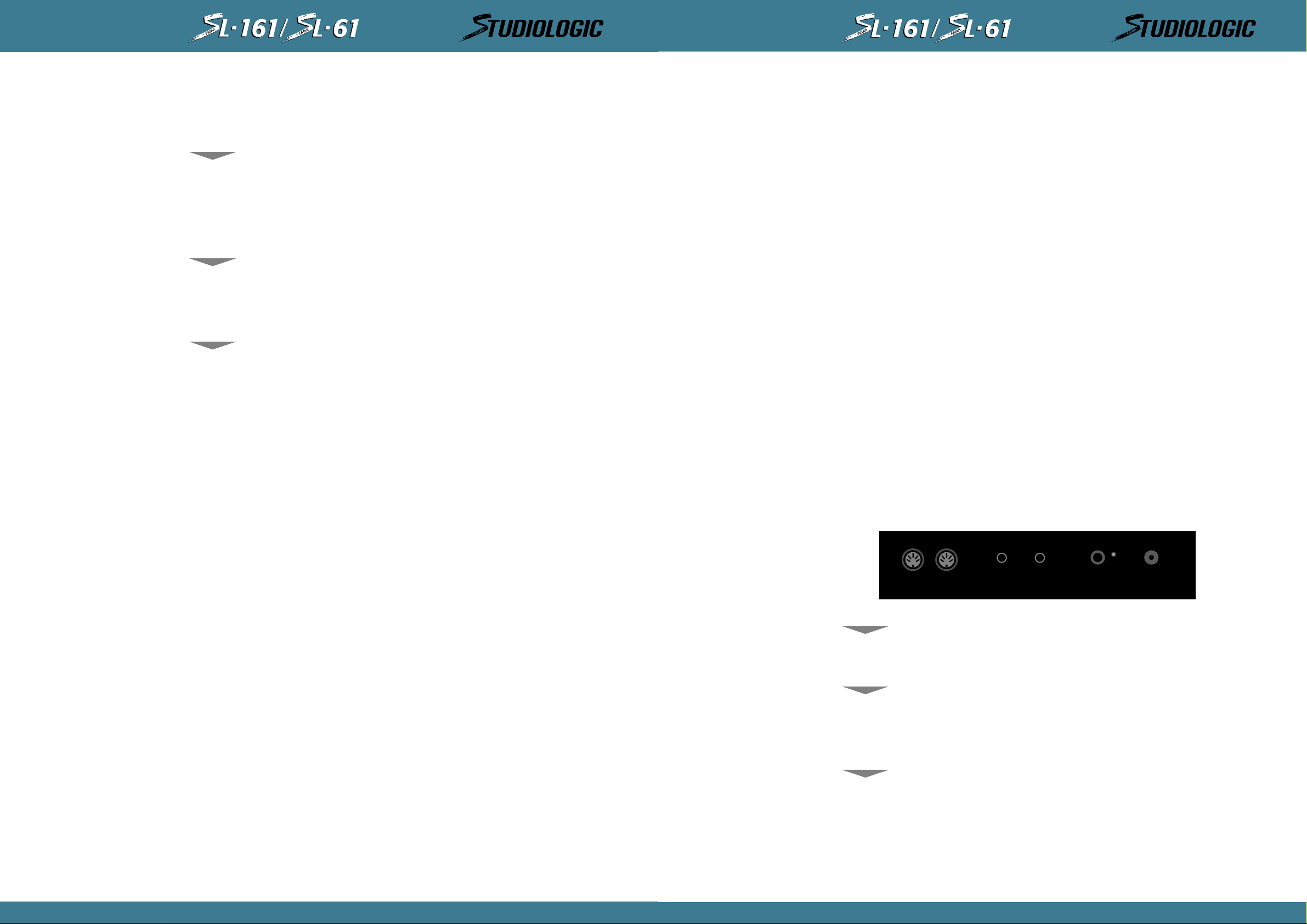
®
MIDICONTROLLERS
®
MIDICONTROLLERS
ESPAÑOL
ESPAÑOL
TECLADO
RUEDAS
ZONAS
CAPÍTULO 2.
Características
Un recorrido por los controles y características de Studio Logic SL-161/SL-61
Studio Logic SL-161/SL-61cuen ta con un teclado de 61 teclas tipo sintetizador de acción contrapesada. Proporciona un toque extremadamente musical con una respuesta muy dinámica a
la vez que rápida en la respuesta. La acción sensible a la velocidad de pulsación puede ser
modificada con varias configuraciones de curva de velocidad de respuesta que serán analizadas más adelante en este manual. Las 61 teclas de SL-161/SL-61 transmiten aftertouch por
canal en todas las zonas.
Las ruedas de modulación y altura tonal son del estilo estándar, sin embargo, están construidas en una nueva te xtura d e cau ch o. Han si d o diseñad as para d ar al músi co un a sensación táctil más sólida durante las operaciones de interpretación y programación para obtener una
respuesta más musical
SL-161/SL-61dispone de 2 zonas independientes cada una de ellas capaz de ser asignada a
cualquier rango de teclas.
Como se ha visto en la introducción de este manual, las zonas son el elemento clave en la
creación de útiles capas y particiones. Cada una de las 2 zonas consiste en:
9.ACTIVAR/DESACTIVAR AFTERTOUCH: se puede configurar cada zona para que responda o no
a la información de aftertouch. Esto se realiza en el modo Edit de cada una de las zonas.
10. FORMA: configuraciones de curva de velocidad de respuesta específicas para cada zona.
Estas configuracion es pueden alterar el modo en que la información de velocidad de pulsación
será transmitida al canal MIDI de recepción. Existen 8 configuraciones de curva de velocidad
entre las que elegir que varían la respuesta dinámica del teclado. De nuevo, estas configuraciones son específicas para cada zona y se puede acceder a ellas desde el modo Edit.
CURVA DE VELOCIDAD GLOBAL: esta curva de velocidad es global, es decir, afecta la respuesta dinámica de todo el teclado en las 2 zonas. Existen 8 configuraciones globales entre las
que elegir accesibles en el modo Edit.
PEDAL SUSTAIN: Studio Logic SL-161/SL-61 dispone de un jack de conexión en el panel trasero para entrada de pedal de sustain.
PEDAL DE VOLUMEN: Studio Logic SL-161/SL-61 dispone de un jack de conexión en el panel
trasero para entrada de pedal de volumen.
ALIMENTACIÓN: Studio Logic SL-161/SL-61 dispone de un jack de conexión en el panel trasero para entrada de la fuente de alimentación incluida.
MEMORIA: Studio Logic SL-161/SL-61 recuer da tod a la inf ormación al apagarse. Todas las configuraciones programadas se transmiten al activar la unidad. No hay necesidad de almacenar
la información editada; al salir del modo de edición la información es almacenada automáticamente.
1. BOTÓN DE ACTIV AR/DES ACTIVAR ZONA: localizado en el panel frontal sobre el mism o teclado. Se utilizan para activar o desactivar las zon as en mod o P erf orman ce . Cada conm utad or funciona independientemente. En otras palabras, puedes tener cualquier combinación de zonas
activada o desactivada en cualquier punto mediante estos botones.
En el modo Edit, estos botones se utilizan para seleccionar la zona que se desea editar.
Mientras se está editando, sólo queda seleccionada una zona a la vez y los botones se activan
y desactivan conforme se selecciona cada zona para editar.
2. SELECCIÓN DE CANAL MIDI: mientras se está en modo Edit, cada zona se puede configurar para transmitir en cualquier de los 16 canales MIDI disponibles. Sólo se puede transmitir
de forma simultánea por un canal MIDI en cada zona
3. SELECCIÓN DE BANCO: después de seleccionar un canal MIDI para transmitir, aún en modo
Edit, se puede seleccionar el comando de cambio de banco. Los comandos son distintos
dependiendo del módulo de sonido externo al que se pretenda acceder. Más información sobre
selección de banco más adelante en este manual.
4. CAMBIO DE PROGRAMA: en el modo Edit se puede seleccionar el programa para cada una
de las zonas. Cada una de ellas puede enviar valores entre 0 y 128 (algunos fabricantes utilizan el esquema 0-127, por lo que puede ser necesario añadir (1) a cada número de programa
para obtener los resultados deseados).
5. PARTICIÓN O RANGO DE NOTAS: esta función de edición permite seleccionar el rango de
notas activas para cada zon a. Las zonas son completam ente in d ependi entes en tre sí y sus puntos de partición pueden superponerse creando capas.
6. TRANSPOSICIÓN: cada zona puede configurarse para transponer su rango de notas en una
gama de 24 semitonos hacia arriba o hacia abajo. En otras palabras, 2 octavas a partir del
valor original del módulo correspondiente.
ENTRADA DE
ALIMENTACIÓN
INTERRUPTOR
DE ALIMENTACIÓN
CAPÍTULO 3.
Panel trasero
Puesta en marcha, conexión de pedales y con el resto del equipo
MIDI OUTPUTS
1
Studio Logic SL-161/SL-61 dispon e de un jack de conexión en el panel trasero para entrada de
la fuente de alimentación. El alimentador suministrado es del tipo 9V DC (200mA min.).
Studio Logic SL-161/SL-61 dispon e de in terruptor d e con exión en el pan el tr asero justo al lad o
de la entrada para la fuente de alimentación. Incorpora también un LED rojo que indica que
la unidad está en funci onami en to. Al poner en m ar cha el teclado se tr an smiten todos los d atos
de configuraciones por las conexiones MIDI Out.
2
SUSTAIN VOLUME
POWER
9V DC 0,2 A
36
7. ACTIVAR/DESACTIVAR PEDAL SUSTAIN: se puede configurar cada zona para que responda
o no a la información de pedal sustain. Esto se realiza en el modo Edit de cada una de las
zonas.
8. ACTIVAR/DESACTIVAR RUEDAS: se puede configurar cada zona para que responda o no a la
información de las ruedas de modulación y altura tonal. Esto se realiza en el modo Edit de
cada una de las zonas.
PEDAL SUSTAIN
Studio Logic SL-161/SL-61 dispon e de un jack de conexión en el panel trasero para entrada de
pedal de sustain. Este jack funciona correctamente tanto con los pedales del tipo "normalmente cerrado" como con los del tipo "normalmente abierto". Al poner en marcha el teclado,
éste reconoce el tipo de pedal conectado, independientemente de la polaridad (por ejemplo,
PS100 o VFP1) Nota: el pedal debe estar conectado antes de conectar el teclado par que éste
reconozca adecuadamente la polaridad.
37
MANUAL DEL USUARIO
MANUAL DEL USUARIO
Page 19

®
MIDICONTROLLERS
®
MIDICONTROLLERS
ESPAÑOL
024579
/H
1
ON
3
OFF
86
ESPAÑOL
PEDAL DE VOLUMEN
CONEXIONES MIDI OUT
Studio Logic SL-161 dispone de un jack de conexión en el panel trasero para entrada de pedal
de volumen estándar que utilice jack estéreo o balanceado. Este control de volumen actuara
simultáneamente sobre el volumen de las 2 zonas.
En los jacks MIDI Out es donde se con ectan las diversas fuentes d e soni do. U tilizan do un cable
MIDI estándar de 5 pines, se conecta la salida MIDI Out de Studio Logic SL-161/SL-61 a las
entradas MIDI In de los distintos módulos de sonido, sintetizadores, etc. Se puede utilizar la
característica Thru de los dispositivos para conectar a otros equipos MIDI si así se desea. Si
es posible, convienen evitar encadenar más de 2 dispositivos de esta forma, para reducir la
posibilidad de que se produzcan atascos y retrasos en la transmisión de datos. Studio Logic
SL-161/SL-61 dispone de 2 conectores MIDI Out en paralelo para ayudar a reducir la posibilidad de que se produzcan retardos en la transmisión de datos al conectarse a múltiples dispositivos MIDI. Al conectar varias unidades a SL-161, es conveniente repartirlas lo más equitativamente posible ente las 2 salidas MIDI.
12
ZONES
MIDI CHANNEL
BANK SELECT
PROGRAM CHANGE
SPLIT
TRANSPOSE
SUSTAIN
UP DOWN ENTER/EDIT
WHEELS
AFTER TOUCH
SHAPE
VELOCITY
UP, DOWN, ENTER/EDIT
TECLADO NUMÉRICO,
(H) Y (-), (ON) Y (OFF)
MIDI CHANNEL
Sólo se puede editar una zona a la vez y por lo tanto sólo se iluminara una de las luces indicadoras mientras se esté en éste modo.
* Por favor, observa que sólo debes usar un botón de zona y activarla o desactivarla mientras
no esté pulsada ninguna nota sobre el teclado ni el pedal sustain.
Los botones Up y Down (Arriba, Abajo) se utilizan para desplazarse entre las distintas funciones mientras se está en el modo de edición.
Pulsar el botón Enter/Edit activa y desactiva el modo de edición. Mientras se está en éste, se
ilumina un LED al lado de la función de edición actual.
Usando los botones Up/Down se desplazarán los LEDs a través de las distintas funciones
Esta es el área en la que se introducen los parámetros deseados para las funciones que están
siendo editadas en cada momento. El teclado numérico, H y - y On y Off se asignan y corresponden con las teclas de la octava central del teclado.
Mientras se está en modo Edit, estas teclas funcionan como dispositivo de entrada de datos y
no transmiten información de nota. En otras palabras, mientras se está en modo de edición,
todo el teclado queda deshabilitado y no transmite información de notas hasta que se sale de
éste modo.
Utilizado para especificar por qué canal MIDI transmitirá su información cada una de las 2
zonas. Para acceder a este parámetro, entra en el modo Edit seleccionando Enter/Edit.
Selecciona la zona d eseada pulsando en su conmutador Zone correspondiente. Usa los botones
Up/Down para seleccionar la función MIDI Channel. Ahora puedes introducir un valor de 1 ó 2
dígitos utilizando el teclado n umérico para configurar el canal de transmisión de la zona. Para
salir del modo de edición, pulsa de nuevo el botón Edit/Enter. Al salir del modo de edición la
nueva información queda almacenada automáticamente en la memoria de SL-161/SL-61 y la
zona queda habilitada par a transmitir información por el nuevo canal. Para poder tocar y transmitir en una zona concr eta, selecci ona el conmutador Zone correspondiente estando en modo
de interpretación y se iluminará el LED correspondiente
SELECCIÓN DE ZONA
(ZONE)
CAPÍTULO 4.
Panel frontal: controles y características
¿Cuáles son, qué hacen? Y, ¿cómo utilizarlos?
Localizados en el panel frontal hay 2 botones Zone para: habilitar y deshabilitar las 2 zonas
de teclado mientras se está en modo interpretación y para selección de zonas mien tr as se está
en modo Edit. Los indicadores LED se iluminarán cuando su zona correspondiente sea activada o seleccionada para editar. Mientras se está tocando (modo Play), cualquier combinación
de zonas puede ser activada o desactivada en cualquier momento deseado. Si embargo, en
modo Edit, los botones de zona sólo pueden ser usados para seleccionar una zona.
BANK SELECT
Usado para transmitir o iniciar un mensaje de cambio de banco en una zona determinada.
Después de seleccionar y asignar el canal MIDI, pulsa el botón Down para conmutar a Bank
Select. Este modo permite cambiar el banco de sonidos en el módulo generador de sonidos o
fuente de sonido externa.
El protocolo de recepción de Bank Select depende del tipo y marca del módulo de sonido al
que se está transmitiendo y puede variar entre distintos fabricantes. Si el módulo que se está
utilizando requiere sólo "Control 32", únicamente será necesario entrar el número de banco
que se desee seleccionar.
Si el módulo requiere un protocolo más completo (Control 32 + Control 0), será necesario
entrar Control 32 y pulsar la tecla correspondiente al símbolo "H" (-de Higher - representa la
parte más alta del byte de cambio de programa). Después se puede proceder a introducir el
número desead o para Con trol 0. La secuen ci a puede ser com o sigue: en trar 32, d espués la tecla
(-) que tiene el símbolo "H" encima y para acabar, el número de banco al que se quiere cambiar.
PROGRAM CHANGE
Utilizado para seleccionar un núm ero d e progr ama o cambi o de pr ogram a para un a zona específica. Para acceder a este parámetro primero se deberá activar la zona deseada seleccionando y
pulsando el correspondiente conmutador Zone, después pulsar Enter/Edit para entrar en el
modo de edición.
Selecciona el botón Zone apropiado para pasar a editar. Después, utilizando Up/Down, selecciona la función Program Change. Introduce el número deseado en el teclado numérico (los
mensajes MIDI de cambio de programa pueden tener un valor entre 0 y 128). Para salir del
modo de edición, pulsa de nuevo el botón Edit/Enter. Al salir de este modo, los nuevos parámetros quedan almacenados en la memoria de SL-161, se transmite el número de programa
seleccionado y se habilita el teclado para que suene el nuevo número de programa.
38
39
MANUAL DEL USUARIO
MANUAL DEL USUARIO
Page 20
®
MIDICONTROLLERS
®
MIDICONTROLLERS
ESPAÑOL
ESPAÑOL
SPLIT
TRANSPOSE
SUSTAIN
Utilizado con el fin de seleccionar el rango específico de notas para una determinada zona.
Para configurar el rango de teclas o partición de una zona, entra en el modo de edición presionando Enter/Edit y utiliza Up o Down hasta que el LED al lado del botón Split quede iluminado. Pulsa el botón Zone para la zona que estés configurando y seguidamente la nota más
baja en el teclado que desees como límite inferi or de la zona. Después la nota del teclado que
vaya a ser el límite superior. Al salir del modo de edición se almacenará la información correspondiente . Los r an gos d e teclas pued en ser desd e una sola n ota (pulsan do d os veces la mism a
tecla en el teclado) hasta la longitud completa de éste. El rango puede ser cualquier combinación de notas adyacentes sobre cualquier punto del teclado y es totalmente independiente
para cada una d e las zonas. Se puede superponer cualquier número de notas entre zona y zona
según sea necesario.
Para transponer el rango de teclas arriba o abajo en una zona en una cantidad específica de
semitonos desde el Do central. Normalmente, las 2 zonas disponen de un valor de transposición 0, lo que quiere decir que el Do central del teclado se corresponde con el Do central de
una partitura de piano de doble pentagrama (siempre y cuando el programa del módulo correspondiente este configurado del mismo modo).
Digamos que quier es transponer el tono de una zona en 4 semitonos. Entra en el modo de edición, selecciona la zona deseada, selecciona la función Transpose utilizando las teclas
Up/Down.
Ahora pulsa "4" en el teclado numérico y ya puedes abandonar el modo de edición. En el caso
de que quisieras tran sponer el ton o una octava hacia abajo, si gue el mismo pr ocedimien to pero
en vez de pulsar "4" en el teclado numéri co, pulsa prim ero la tecla "-", d espués "12" y ya puedes salir de edición. Se puede transponer un máximo de +/- 24 semitonos (2 octavas) entrando un número positivo o negativo hasta 24. Los valores positivos se introducen pulsando las
teclas correspondientes a los números deseados; los valores negativos pulsando primero la
tecla "-" y seguidamente el valor numérico correspondiente.
Esta función permite activar o desactivar el pedal sustain para cada una de las zonas. Por
ejemplo, si deseas desactivar dicho pedal en la zona 2: estando en el modo de edición, utiliza las teclas Up/Down hasta llegar a la función Sustain; observa como se ilumina el LED correspondiente. Ahora, pulsa el botón de la zona 2 para poder editarla y seguidamente el botón
Off que se corresponde con la tecla Mib sobre el teclado. La zona 1 quedará afectada por la
acción sobre el pedal de sustain y la zona 2 no. Para volver a activarlo, selecciona Edit,
Sustain y pulsa en On.
Una aplicación obvia para esta función es desactivar el pedal sustain en una zona situada en
la zona más grave del teclado que esté configurada con un sonido de bajo o contrabajo.
Además, ahora puedes utilizar la segunda zona para tocar un piano o una capa colchón dejando el pedal sustain activado en ella.
la parte grave del teclado que suenen como si estuvieran tocados en la gama media cercana
al Do central. Deja el pedal sustain activado pero deshabilita las ruedas en esta zona. Ahora
usa la zona restante para crear una capa utilizando las notas más altas que están sin usar.
Asigna esta zona a un sonido para solo, desactiva el pedal sustain en esta parte pero deja las
ruedas activas. Ahora puedes tocar y mantener acordes en la parte grave utilizando el pedal
sustain para "fijar" los acordes. Después, usando las dos manos puedes tocar un solo encima,
utilizando la mano derecha para tocar las notas y la izquierda para actuar sobre las ruedas de
expresión; suelta el pedal sustain para cambiar de acorde y vuelve a "fijar" de nuevo el acorde y sigue tocando sobre la nueva armonía.
AFTERTOUCH
Esta función permite activar o desactivar la post-pulsación (Aftertouch) en cada una de las
zonas. Por ejemplo, si deseas desactivarlas en la zona 2: estando en el modo de edición, utiliza las teclas Up/Down hasta llegar a la función Aftertouch; observa como se ilumina el LED
correspondiente. Ahora, pulsa el botón de la zona 2 para poder editarla y seguidamente el
botón Off que se corresponde con la tecla Mib sobre el teclado. La zona 1 quedará afectada
por la acción sobre las ruedas y la zona 2 no. Para volver a activarlo, selecciona Edit,
Aftertouch y pulsa en On.
Una aplicación de esta característica puede ser como sigue: refiérete a la configuración del
ejemplo anterior sobre las rued as de e xpresión. En el soni d o para solo d e la m ano d erecha puedes estar utilizando el efecto aftertouch para cambios de volumen y modulación de vibrato.
Mientras estás haciendo esto observarás que se envían mensajes de vibrato no deseados a los
acordes sostenidos de las zona más grave del teclado. Utiliza esta función para desactivar el
efecto en esa zona; de este modo evitarás que los mensajes de post-pulsación de la zona de
solo afecten al sonido de la zona de acordes.
SHAPE
Esta función permite cambiar las curvas de respuesta dinámica que controlan la respuesta a la
velocidad de ejecución para cada una de las 2 zonas. Esto permite adaptar tu teclado maestro
a la respuesta dinámica de tu mód ulo o mód ulos d e sonido u otros dispositivos MIDI e xtern os .
También permite adaptar la reacción del teclado a tu particular estilo de interpretación. La
función Shape de Studio Logic SL-161/SL-61 te ofrece 8 curvas preconfiguradas entre las que
puedes elegir, 4 positivas y 4 negativas. Cada zona puede tener su propia curva de respuesta.
Para seleccionar una de estas para una zona sigue el modo de edición habitual. Entra en el
modo de edición, selecciona una zona pulsando sobre el botón Zone correspondiente, selecciona la función Shape utilizando los botones Up/Down y finalmente los números 1, 2, 3 ó 4.
Pulsando "-" antes de seleccionar el número configurará una versión negativa de la curva. Por
curva negativa entend emos aquella que pr opor cion a un efecto inverso con respecto a la acción
sobre el teclado. Un toque suave da una respuesta muy alta y viceversa.
Esta función es muy útil cuando se tienen dos curvas distintas, una positiva y otra negativa,
en dos zonas, lo que d a como resultado un efecto de entrecruzamiento en la velocidad de pulsación (velocity crossfade). Cuando un sonido se suaviza el otro suena más alto. Shape (-)1
es la versión invertida de Shape 1 y así siguiendo.
WHEELS
40
Esperamos que estés empezando a ver las posibilidades a tu alcance al utilizar el controlador
maestro Studio Logic. Con sólo un poco de creatividad de tu parte puedes dar con interesantes y útiles configuraciones para tus particulares necesidades musicales.
Esta función permite activar o desactivar las 2 ruedas en cada una de las zonas. De nuevo,
como ejemplo, si deseas desactivarlas en la zona 1: estando en el modo de edición, utiliza las
teclas Up/Down hasta llegar a la función Wheels; observa como se ilumina el LED correspondiente. Ahora, pulsa el botón de la zona 1 para poder editarla y seguidamente el botón Off
que se corresponde con la tecla Mib sobre el teclado. Desactiva el modo de edición pulsando
en botón Enter/Edit. La zona 2 quedará afectad a por la acción sobr e las rued as y la zon a 1 n o.
Para volver a activarlo, sigue los mismos pasos que en el ejemplo del párrafo anteri or per o realiza la acción correspondiente al botón On en el teclado (Reb central).
Una posible aplicación de esta característica puede ser disponer de una zona asignada a la
parte grave del teclado con soni dos sostenid os tipo colchón, con las partes más altas acaban do
aproximadamente en el centro del teclado, dejando espació para una partición más arriba.
Quizás puedas transpon er la zon a baja un a octava hacia arriba de modo que toques acordes en
SHAPE 1 tiene una respuesta lineal, compatible con la mayoría de dispositivos MIDI del mercado. Esta es la configuración por defecto para cada una de las 2 zonas.
SHAPE 2 tiene una respuesta algo menos sensible por lo que requiere un toque más enérgico.
Esta configuración proporciona una respuesta dinámica más amplia. Pruébala en un piano o
piano eléctrico mientras estés tocando una balada para disponer de un toque con más expresividad. También puede ser adecuada si utilizas SL-161/SL-61 para programar batería o percusiones en un secuenciador, ya que facilita hacer sobresalir los "golpes" y admite una gran
variedad en los acentos. Es también útil cuando el dispositivo MIDI que genera los sonidos es
demasiado sensible y deseas bajar los volúmenes relativos que se están transmitiendo
SHAPE 3 tiene una respuesta más sensible que Shape 1, lo que permite transmitir valores de
velocidad MIDI más altos tocando de una forma más suave. Especialmente útil con piano de
rock o blues honky-tonk o si es necesario hacerse escuchar en un grupo que suena fuerte.
Escala todos los volúmenes relativos aumentándolos.
SHAPE 4 dispone de una respuesta aún más sensible. Util para eliminar parte o la totalidad
de la respuesta dinámica del teclado al disparar muestras, bucles o efectos de modo que se
reproduzcan a su volumen máximo sin necesidad de tocar muy fuerte.
41
MANUAL DEL USUARIO
MANUAL DEL USUARIO
Page 21

®
MIDICONTROLLERS
®
MIDICONTROLLERS
ESPAÑOL
024579
/H
1
ON
3
OFF
86
ESPAÑOL
VELOCITY
TECLADO NUMÉRICO,
(H) Y (-), (ON) Y (OFF)
Esta función es similar en aplicación a la anterior en tanto que ambas corresponden a configuraciones de respuesta dinámica para el teclado y la información de volumen MIDI que se
transmite. La diferencia está en que este parámetro es global. Al seleccionarlo estando en el
modo de edición, se encienden simultán eam en te los LEDs d e las 2 zon as in di can d o que se está
manipulando un parámetro global que afecta a todas las zonas. Mientras en el párrafo anterior se seleccionaba una curva de respuesta para una zona en concreto, ahora dispones de 8
curvas diferentes que afectan a la respuesta d e tod o el teclado. Este parámetro Velocity puede
ayudar a adaptar tu controlador maestro a los módulos MIDI o a tus características específicas de interpretación o estilo para proporcionarte el control más expresivo disponible.
Para seleccionar una curva Velocity, entra en el modo de edición, utiliza los botones Up/Down
hasta llegar a la función del mismo nombre, entonces elige entre 1 y 8 en el teclado numérico. Abandona el modo de edición para tocar y probar cada una de las distintas curvas.
Como ya te habrás figurado al llegar a este punto del manual, Studio Logic SL-161/SL-61 utiliza en modo de edición el propio teclado como teclado numérico y como medio para la entrada de datos. Las teclas de la octava central, comenzando en el Do central, están asignadas a
funciones específicas para entrada de datos y están etiquetadas de forma clara. Mientras se
está en modo de edi ción y utilizan d o el teclad o n uméri co, el teclad o n o tr ansmite información
MIDI. Debes salir del modo de edición para poder tocar notas en el teclado.
RECONFIGURACIÓN
GENERAL
INFORMACIÓN GENERAL
DE PROGRAMACIÓN
Para reconfigurar la unidad a los valores de fábrica del párrafo anterior:
• Poner en marcha el teclado mientras se mantienen pulsados simultáneamente los botones
Up/Down/Enter, aguantando unos segundos para después soltarlos.
• Cuando el controlador maestro se pone en marcha siempre transmite el contenido de la memoria de programas.
• Después de program ar cualqui er parámetr o, el conteni do d e la mem oria es tr ansmiti do al salir
del modo de edición.
• Para transmitir el contenido de la memoria mientras se está en modo de interpretación se
puede pulsar el botón Enter/Edit dos veces.
• Al salir del modo de edición se almacenan automáticamente en la memoria todos los pará
metros que han sido cambiados.
• Al apagar la unidad toda la información en memoria es retenida y más tarde transmitida al
poner en marcha de nuevo la unidad.
• No se puede entrar en el modo de edición si se están pulsando teclas o activando el pedal
sustain. Se deben dejar de pulsar todas las teclas y pedales antes de entrar en el modo de
edición.
• Al entrar de nuevo al modo de edición, esté estará posicionado en el parámetro y zona en
el que se encontraba al abandonarlo en la anterior sesión de edición.
• Cuando se selecciona el modo de edición, el teclado no emite ningún tipo de sonido. Para
probar las variaciones programadas y poder tocar el teclado se debe salir del modo Edit.
CONFIGURACIÓN POR
DEFECTO
CAPÍTULO 5.
Programando el controlador maestro Studio Logic SL-161/SL-61.
Creando programa útiles musicalmente y cómo hacerlo.
Antes de entrar a ver algunos ejemplos y consejos de programación, la siguiente información
versa sobre la arquitectura del diseño y operación del controlador maestro Studio Logic SL161/SL-61.
Cuando el controlador maestro es activado por primera vez transmite la siguiente configuración por defecto:
• Zona 1 On, zona 2 Off. Las 2 zonas están configuradas para transmitir en los canales MIDI
1 y 2 respectivamente, su punto de partición está configurado en la extensión completa de
las 61 teclas y todos los comandos conmutables están en la posición On.
• Todas las zonas están configuradas con la curva de respuesta 1, Velocity = 4, Transpose = 0.
• Configuración de volumen al valor 127 si no hay pedal de volumen conectado. Al conectar
el pedal, cualquier posición en la que éste se encuentre será transmitida.
• Sustain Off (el pedal está habilitado pero en la posición Off, CC 64 = 0).
• Pitch Bend = 0, rueda de modulación = 0.
APLICACIONES Y
CONSEJOS PARA
EL USUARIO
ZONAS
Estas sugerencias han sido diseñadas como punto de inicio para estimular el uso creativo de
estas características para tus propias necesidades y aplicaciones musicales.
Las zonas son el corazón del controlador maestro SL-161. El uso creativo de sus parámetros y
de las zonas en sí mismas proporci ona al músico una nueva flexibilidad y capacidad de control
sobre los sonidos y módulos.
Ya se ha visto como operar con las zonas. Ahora se aplicarán en un entorno musical. Se pueden usar las 2 zonas en una buena variedad de formas. Aquí hay algunas opciones y posibles
aplicaciones utilizando las características de este teclado:
La gran capa: configura las 2 zonas en el mismo rango de notas y asígnalas a dos sonidos de
cuerda o de piano similares. Prueba con un sonido de piano y uno de cuerdas. Experimenta
desactivando algunas de las características como Aftertouch y Sustain en alguna zona.
Mientras tocas una sección de un tema, deja alguna de las capas desactivadas y luego actívalas durante el estribillo pulsan do los botones Zone correspondientes, así incrementaras la sensación dinámica de tu interpretación. Prueba a configurar los sonidos de piano en tu módulo
de modo que no respondan a mensajes de volumen MIDI (CC 7) y utiliza un pedal de volumen
en el controlador maestro para poder hacer entrar las cuerdas detrás del piano cuando sea
necesario.
La partición: configura una zona en la mano izquierda para una capa piano eléctrico o colchón y otra en la mano derecha para una cuerda solista o viento. Usa la función de transposición para que las zonas estén en un rango de notas apropiado.
¿Otra partición?: Prueba con un sonido de bajo utilizando una zona en las dos octavas más
graves del teclado, d esactiva el pedal sustain y efectúa una transposición de una octava hacia
arriba para situarte en el ran g o d e un bajo eléctri co. Ah or a cr ea un a parti ción en el r a n g o central con la zona 2 con sonidos de acompañamiento. Ahora puedes tocar una línea de bajo con
la mano izquierda y acompañar con acordes con la mano derecha.
* Nota sobre las particiones: recuerda siempre utilizar la función Transpose para emplazar las
partes en un rango de interpretación adecuado sin que importe el lugar físico del teclado en que
se encuentren.
Piensa en el teclado como en 61 teclas o disparadores disponibles para experimentar más que
en su emplazamiento tradicional como piano acústico.
42
43
MANUAL DEL USUARIO
MANUAL DEL USUARIO
Page 22

®
MIDICONTROLLERS
ESPAÑOL
®
MIDICONTROLLERS
ESPAÑOL
ALGUNOS CONSEJOS
MÁS INCLUIDOS PARA
TU CONSIDERACIÓN
Aplicaciones en vivo y en estudio.
• Aplicación en vivo: intenta usar las diferen tes curvas d e respuesta en cada zona para mani-
pular y balancear los elementos en las capas.
• Aplicación en estudio: conecta MIDI Out de SL-161/SL-61 a MIDI In en el secuenciador y
MIDI Out del secuenciad or a MIDI In de tus mód ulos . Configur a el filtr o de en tr ad a del secuenciador en Direct Echo o el parámetro adecuado para pasar toda la información a través de él
sin canalizarla. Si das con un interesante conjunto de capas pon el secuenciador a grabar en
modo multipistas y pulsa Enter dos veces mientras el secuenciador está grabando para grabar
tus cambios de programa y luego continúa tocando mientras se graba una interpretación con
todas tus capas. Para otra sección de la composición puedes hacer lo mismo con otro grupo
de sonidos y grabar y automatizar los cambios de programa con tu interpretación.
Utilizando las capas en SL-161/SL-61 puedes dar con combinaciones de sonidos y partes que
no habrías podido concebir de la manera tradicional (una pista por vez).
• Aplicación en vivo: usa las curvas de sensibili d ad invertid as par e xperim entar con los en tr e-
cruzamientos de volumen.
• Aplicación en vivo: configura una zona de forma que su rango sea de tan solo una nota. Al
editar el parámetro Split, pulsa la misma nota dos veces (la más grave o la más aguda en el
teclado). Asigna esta zona a un canal MIDI que transmita a tu sampler para disparar un loop
o un efecto de sonido. Utiliza la función de transposición para subir o bajar la afinación de la
muestra. Si el rango de transposición no resulta suficiente, asigna la nota que dispara la muestra a una apropiada en el sampler y sálvala de este modo.
• Aplicación en vivo o estudio: usa la función Bank Select para acceder a esos sonidos alter-
nativos que no están almacenados en las primeras 127 posiciones de tu sintetizador.
• Aplicación en vivo: usa las 2 zonas para configurar 2 programas distintos, usa los botones
Zone para tocar con un sonido distinto en distintas partes de un mismo tema.
• Aplicación en vivo o estudio: usa la función Transpose para crear intervalos desde zonas
por capas en octavas o armonizadas.
• Aplicación en estudio:
partición configurada en SL-161/SL-61 para grabar simultáneamente dos pistas, bajo y acompañamiento o acordes y melodía. El punto es, crea utilizando todas estas nuevas posibilidades.
• Aplicación en estudio, música para imágenes: quizás tu secuenciador puede ser esclavi-
zado a video vía SMPTE. Configura una partición con todos los elementos orquestales, toca en
vivo mientras estas viendo las imágenes. Salta a otro sonido conforme las imágenes te inspiren mientras estás grabándolo todo simultáneamente al secuenciador en modo multipistas.
Después, tendrás todos tus instrumentos cada uno en su propia pista; ahora puedes editar o
elaborar sobre tu improvisación. Si el secuen ciador no graba canales MIDI separados en pistas
separadas siempre puedes filtrar por canal después de grabar para separar todo el material en
pistas individuales de ca ra a l a e dición.
usa grabación multipistas en tu secuenciador pero esta vez con una
DIAGRAMAS:
MODEL SL-161/SL-61
STUDIO LOGIC
MASTER CONTROLLER
“SPLIT NOTE” KEY RANGE FOR ZONE#1
LOW NOTE ________ HIGH NOTE ________
——————————————————————————————————————
—————————————————————————
“SPLIT NOTE” KEY RANGE FOR ZONE#2
LOW NOTE ________ HIGH NOTE ________
——————————————————————————————————————
—————————————————————————
ZONE # 1 ZONE # 2
MIDI CHANEL:
BANK SELECT:
PATCH NUMBER:
TRANSPOSE:
SUSTAIN PEDAL:
WHEELS:
AFTERTOUCH:
SHAPE:
GLOBAL SETTING VELOCITY CURVE: __________
Patch Name: ______________ Description: ______________
Comments: ______________________________________________
——————————————————————————————————————
—————————————————————————
“SPLIT NOTE” KEY RANGE FOR ZONE#1
Comments or notes:
DIAGRAMAS:
MODEL SL-161 STUDIO
LOGIC MASTER CONTROLLER
44
CAPÍTULO 6
Diagramas
Diagramas y gráficos útiles
Incluidas en las siguientes dos paginas hay dos copias idénticas de una plantilla en la que
puedes escribir configuraci ones d e tus pr ogram as . Las in cluimos par a que pued as construir un a
librería con tus configuraciones favoritas.
Patch Name: ______________ Description: ______________
Comments: ______________________________________________
——————————————————————————————————————
—————————————————————————
LOW NOTE ________ HIGH NOTE ________
——————————————————————————————————————
—————————————————————————
“SPLIT NOTE” KEY RANGE FOR ZONE#2
LOW NOTE ________ HIGH NOTE ________
——————————————————————————————————————
—————————————————————————
45
MANUAL DEL USUARIO
MANUAL DEL USUARIO
Page 23

®
MIDICONTROLLERS
®
MIDICONTROLLERS
ESPAÑOL
MIDI CHANEL:
BANK SELECT:
PATCH NUMBER:
TRANSPOSE:
SUSTAIN PEDAL:
WHEELS:
AFTERTOUCH:
SHAPE:
ZONE # 1 ZONE # 2
Comments or notes:
ESPAÑOL
SOLUCIÓN
DE PROBLEMAS
PROBLEMA
Posible solución
Posible solución
CAPÍTULO 7
Apéndice
El teclado no se pone en marcha
• Asegurar que la fuente de alimentación está conectada correctamente en la toma de corriente
• Asegurar que la fuente de alimentación está conectada al teclado
PROGRAMAS
GENERAL MIDI
GLOBAl SETTING VELOCITY CURVE: __________
El siguiente diagrama muestra los números de programa General MIDI. Si estás utilizando un
módulo o teclado GM te vendrá bien.
1. Piano 1 43. Cello 86. Solo Vox
2. Piano 2 44. Contra Bass 87. Fifths
3. Piano 3 45. Tremolo Strings 88. Bass Lead
4. Honky Tonk 46. Pizzicato Strings 89. Fantasia
5. Electric Piano 1 47. Harp 90. Warm Pad
6. Electric Piano 2 48. Timpani 91. Poly Synth
7. Harpsichord 49. Strings 92. Space Vox
8. Clavinet 50. Slow Strings 93. Bow Glass
9. Celesta 51. Synth Strings 1 94. Metal Pad
10. Glockenspiel 52. Synth Strings 2 95. Halo Pad
11. Muic Box 53. Choir Aahs 96. Sweep Pad
12. Vibraphone 54. Voice Oohs 97. Ice Rain
13. Marimba 55. Synth Voice 98. Sound Track
14. Xylophone 56. Orchestra Hit 99. Crystal
15. Tubular Bell 57. Trumpet 100. Atmosphere
16. Dulcimer 58. Trombone 101. Brightness
17. Electric Organ 1 59. Tuba 102. Goblin
18. Electric Organ 2 60. Muted Trumpet 103. Echo Drop
19. Electric Organ 3 61. French Horn 104. Star Theme
20. Church Organ 62. Brass Section 105. Sitar
21. Reed Organ 63. Synth Brass 1 106. Banjo
22. Accordion 64. Synth Brass 2 107. Shamishen
23. Harmonica 65. Soprano Saxophone 108. Koto
24. Bandonion 66. Alto Saxophone 109. Kalimba
25. Nylon Guitar 67. Tenor Saxophone 110. Bagpipe
26. Steel Guitar 68. Baritone Saxophone 111. Fiddle
27. Jazz Guitar 69. Oboe 112. Shanai
28. Clean Guitar 70. English Horn 113. Tinkle Bell
29. Muted Guitar 71. Bassoon 114. Agogo
30. Drive Guitar 72. Clarinet 115. Steel Drum
31. Lead Guitar 73. Piccolo 116. Wood Block
32. Harmonic Guitar 74. Flute 117. Taiko
33. Acoustic Bass 75. Recorder 118. Melody Tom
34. Finger Bass 76. Pan Flute 119. Synth Drum
35. Pick Bass 77. Bottle Blow 120. Reversed Cymbal
36. Fretless Bass 78. Shakuhachi 121. Guitar Noise
37. Slap Bass 1 79. Whistle 122. Key Click
38. Slap Bass 2 80. Ocarina 123. Seashore
39. Synth Bass 1 81. Square 124. Birds
40. Synth Bass 2 82. Sawtooth 125. Telephone
41. Violin 83. Calliope 126. Helicopter
42. Viola 84. Chiffer 127. Applause
85. Charang 128. Gunshot
PROBLEMA
Posible solución
Posible solución
Posible solución
Posible solución
PROBLEMA
Posible solución
PROBLEMA
Posible solución
Posible solución
PROBLEMA
Posible solución
Posible solución
PROBLEMA
Posible solución
PROBLEMA
Posible solución
Posible solución
PROBLEMA
Posible solución
Posible solución
Posible solución
El teclado parece no enviar datos MIDI a los módulos
• Asegurar que la zona en la que se esta tocando está activada
• Asegurar que la fuente de alimentación está conectada al teclado
• Asegurar que el canal MIDI por el que se está transmitiendo está habilitado en el módulo
generado r de so n idos
• Asegurar que las salidas de audio están correctamente conectadas al amplificador o mezclador
Los cambios realizados en el modo de edición parece que no se activan al volver al modo
interpretación
• Al entrar en el modo edición, asegurar que se está actuando sobre la zona en la que se está
tocando
Los datos MIDI llegan al módulo porque el LED indica actividad de transmisión pero no
se oye nada...
• Asegurar que el pedal de volumen está en la posición correcta
• Asegurar que las salidas de audio están correctamente conectadas al amplificador o mezclador
El pedal sustain no funciona
• Asegurar que el pedal está conectado en la entrada correcta
• Asegurar que el pedal está habilitado para la zona en la que se está tocando en este momento
El pedal sustain está funcionando al revès
• Apagar el teclado. Con el pedal en la entrada correcta volver a activar el teclado, de este
modo SL-161/SL-61 comprobará la polaridad del pedal y se ajustar apropiadamente
Las ruedas y la post-pulsación no funcionan
• Asegurar que las funciones están habilitadas en la zona en la que se está tocando es este
momento
• Asegurar que las funci on es están habilitad as en el pr ogr am a d el mód ulo al que se dirigen los
datos MIDI
Estoy tocando en una zona que sè que está activada pero no suena
• Asegurar que se está tocando dentro del rango de notas habilitadas en esa zona en concreto
• Asegurar que el canal MIDI está configurado correctamente
• Asegurar que el pedal de volumen está presionado y los otros parámetros de volumen están
activados
46
47
MANUAL DEL USUARIO
MANUAL DEL USUARIO
 Loading...