

Page 1
8300 LIQUID FERTILIZER APPLICATOR
OPERATION MANUAL
FAST GLOBAL SOLUTIONS
990 8300 Liquid Fertilizer Applicator 4-16-2019
Page 2

990 8300 Liquid Fertilizer Applicator 4-16-2019
Page 3

General Information
All rights, especially copying and distribution rights are reserved. No part of this publication may be reproduced in
any form or by any means, electronic or mechanical, including photocopying, without express written permission
from FAST AG Solutions.
Parts information in this manual represents components installed when product was manufactured based upon
the best available information. Modifications made subsequent to initial delivery are not included. Always verify
the parts and color required with FAST AG Solutions at 1-800-772-9279.
If you have any questions, please contact your dealer or our Parts and Service Department.
8300 Liquid Fertilizer Applicator 2 FAST AG Solutions
Page 4

Limited Warranty
FAST AG Solutions warrants to the buyer that the new machinery is free from defects in material and workmanship.
This warranty is only effective as to any new machinery which has not been altered, changed, repaired or
treated since its delivery to the buyer, other than by FAST AG Solutions or its authorized dealers or employees, and does not apply to accessories, attachments, tools or parts, sold or operated with the new machinery,
if they have not been manufactured by FAST AG Solutions.
FAST AG Solutions shall only be liable for defects in the materials or workmanship attributable to faulty material or bad workmanship that can be proved by the buyer, and specifically excludes liability for repairs arising
as a result of normal wear and tear of the new machinery or in any other manner whatsoever, and without limiting the generality of the foregoing, excludes application or installation of parts not completed in accordance
with FAST AG Solutions operator’s manual, specifications, or printed instructions.
Written notice shall be given by registered mail, to FAST AG Solutions within seven (7) days after the defect
shall have become apparent or the repairs shall have become necessary, addressed as follows:
FAST AG Solutions
4130 Commerce Boulevard
Windom, MN 56101
This warranty shall expire one (1) year after the date of delivery of the new machinery.
If these conditions are fulfilled, FAST AG Solutions shall at its own cost and at its own option either repair or
replace any defective parts provided that the buyer shall be responsible for all expenses incurred as a result of
repairs, labor, parts, transportation or any other work, unless FAST AG Solutions has authorized such
expenses in advance.
The warranty shall not extend to any repairs, changes, alterations, or replacements made to the new equipment other than by FAST AG Solutions or its authorized dealers or employees.
This warranty extends only to the original owner of the new equipment.
Rubber parts (including tires, hoses, grommets) are not warranted.
This warranty is limited to the terms stated herein and is in lieu of any other warranties whether express or
implied, and without limiting the generality of the foregoing, excluded all warranties, express or implied or conditions whether statutory or otherwise as to quality and fitness for any purpose of the new equipment. FAST
AG Solutions disclaims all liability for incidental or consequential damages.
This Applicator is subject to design changes and FAST AG Solutions shall not be required to retrofit or
exchange items on previously sold units except at its own option.
Warranty void if not registered.
8300 Liquid Fertilizer Applicator 3 FAST AG Solutions
Page 5

FAST AG SOLUTIONS
LIQUID FERTILIZER APPLICATOR
Warranty Registration Form & Inspection Report
Warranty Registration
This form must be filled out by the dealer and signed by both the dealer and the customer at the time of delivery.
Customer Name
Address
City State Zip
Phone
Dealer Name
Address
City State Zip
Applicator Model
Serial Number
Delivery Date
DEALER INSPECTION REPORT SAFETY
____All Fasteners Tight ____ Safety Chain Installed
____Wheel Bolts Torqued ____ All Guards Installed
____Hydraulic Hoses and Fittings Free and Tight ____ All Safety Signs Installed
____Fertilizer Hoses and Fittings Free and Tight ____ Reflectors, SMV and Lights Clean
____Wheel Drive Turns Freely ____ Review Operating and
____Lubricate Machine Safety Instructions
____Check Tire Pressure
____Frame and Wings Level
____Monitors and Controllers Function
____Wiring Harness Connected
I have thoroughly instructed the buyer on the above described equipment which review included the Operator’s
Manual content, equipment care, adjustments, safe operation and applicable warranty policy.
Date_____________________
Dealer’s Rep. Signature___________________________________________________
The above equipment and Operator’s Manual have been received by me and I have been thoroughly instructed
as to care, adjustments, safe operation and applicable warranty policy.
Date_____________________
Owner’s Signature________________________________________________________
White - FAST AG Solutions
Yellow - Dealer
Pink - Customer
8300 Liquid Fertilizer Applicator 4 FAST AG Solutions
Page 6

Contents
General Information................................................................................................................ 2
Fast AG Solutions Warranty Policy........................................................................................ 3
Liquid Fertilizer Applicator Registration............................................................................... 4
Serial Number Location.......................................................................................................... 7
1 Introduction................................................................................................................................ 7
2 Safety.......................................................................................................................................... 8
2.1 Safety Alert Symbol And Signal Words........................................................................... 8
2.2 General Safety.................................................................................................................... 9
2.3 Operating Safety.............................................................................................................. 9
2.4 Maintenance Safety......................................................................................................... 10
2.5 Hydraulic Safety............................................................................................................... 10
2.6 Transport Safety.............................................................................................................. 11
2.7 Storage Safety.................................................................................................................. 12
2.8 Tire Safety........................................................................................................................ 12
2.9 Safety Signs..................................................................................................................... 12
2.10 Sign-Off Form................................................................................................................. 13
2.11 Safety Sign Locations................................................................................................... 14
3 Operation.................................................................................................................................. 17
3.1 New Operator Or Owner.................................................................................................. 17
3.2 Machine Components..................................................................................................... 18
3.3 Break-In............................................................................................................................ 19
3.4 Pre-Operation Checklist.................................................................................................. 19
3.5 Equipment Matching....................................................................................................... 20
3.6 Controls............................................................................................................................ 20
3.7 Attaching/Unhooking Tractor......................................................................................... 21
3.8 Machine Setting............................................................................................................... 22
3.9 Field Operation................................................................................................................ 23
3.10 Transport........................................................................................................................ 29
3.11 Storage........................................................................................................................... 30
3.11.1 Placing In Storage.................................................................................................... 30
3.11.2 Removing From Storage.......................................................................................... 30
4 Service And Maintenance........................................................................................................ 31
4.1 Service.............................................................................................................................. 31
4.1.1 Fluids And Lubricants....................................
4.1.2 Greasing..................................................................................................................... 31
4.1.3 Servicing Intervals..................................................................................................... 33
4.1.4 Service Record........................................................................................................... 33
8300 Liquid Fertilizer Applicator 5 FAST AG Solutions
........................................................... 31
Page 7

4.2 Maintenance..................................................................................................................... 34
4.2.1 Adjust Gauge Wheel Height...................................................................................... 34
4.2.2 Nozzles........................................................................................................................ 34
4.2.3 Filter............................................................................................................................. 34
5 Troubleshooting....................................................................................................................... 35
6 Specifications........................................................................................................................... 35
6.1 Mechanical....................................................................................................................... 35
6.2 Hydraulic Fitting Torque....................................................................................................... 37
8300 Liquid Fertilizer Applicator 6 FAST AG Solutions
Page 8
Serial Number Location
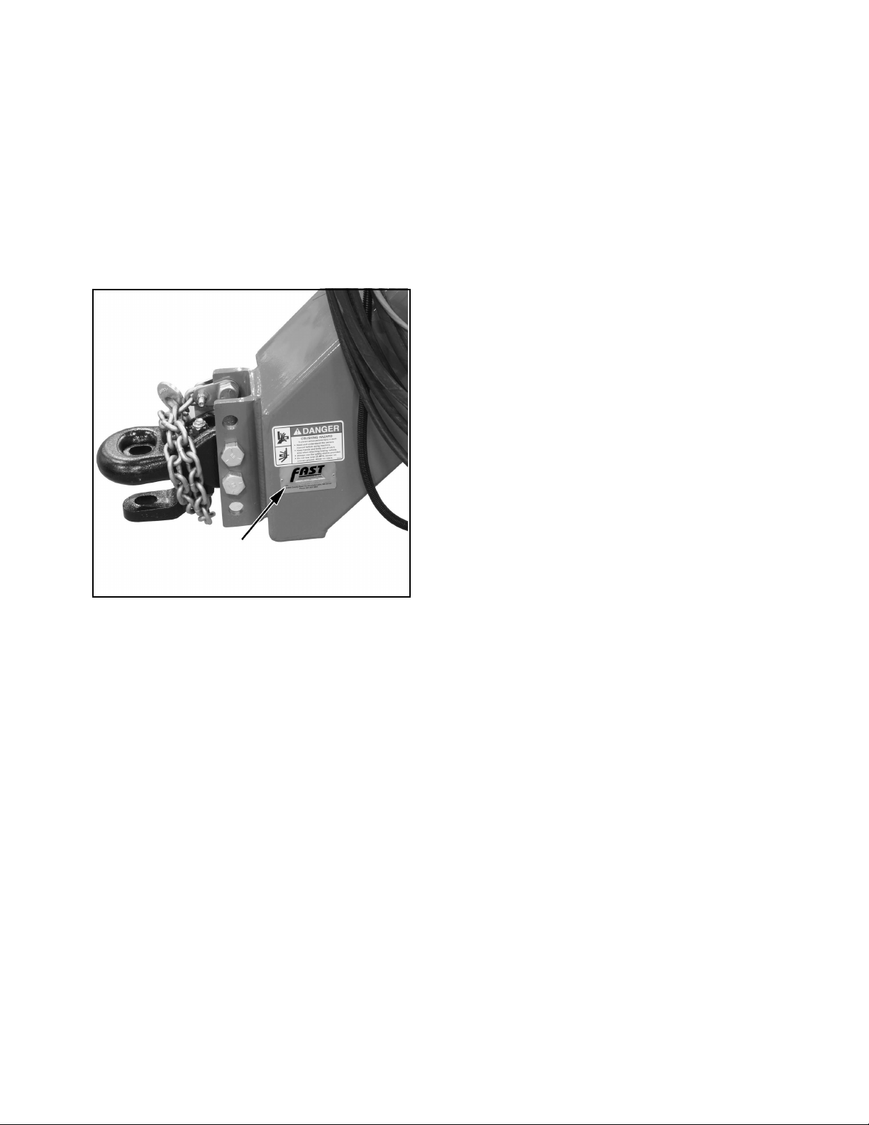
Always give your dealer the serial number of your
FAST AG Solutions Liquid Fertilizer Applicator when
ordering parts or requesting service or other
information.
The serial number is stamped into the frame where
indicated. Please write number in space provided for
easy reference.
1. Introduction
Congratulations on your choice of a FAST AG
Solutions Liquid Fertilizer Applicator to complement
your operation. This equipment has been designed
and manufactured to meet the needs of a
discriminating buyer for the efficient application of
liquid fertilizer.
Safe, efficient and trouble free operation of your FAST
AG Solutions Liquid Fertilizer Applicator requires that
you and anyone else who will be operating or
maintaining the applicator, read and understand the
Safety, Operation, Maintenance and Trouble Shooting
information contained in the Operator’s Manual.
This manual covers the 8300 Series Liquid Fertilizer
Applicators built by FAST AG Solutions. Use the Table
of Contents as a guide when searching for specific
information.
Model Number _____________________________
Applicator Serial Number_____________________
Keep this manual handy for frequent reference and to
pass on to new operators or owners. Call your FAST
AG Solutions dealer or distributor if you need
assistance or information.
OPERATOR ORIENTATION - The directions left,
right, front and rear, as mentioned throughout this
manual, are as seen from the tractor driver’s seat and
facing in the direction of travel.
If you have any questions not answered in this manual
or require additional copies or the manual is damaged,
please contact your dealer or
Fast AG Solutions
4130 Commerce Boulevard
Windom, MN 56101
(Telephone) 507-427-3861
(FAX) 507-427-3030.
8300 Liquid Fertilizer Applicator 7 FAST AG Solutions
Page 9
2. Safety
YOU are responsible for the SAFE operation and
maintenance of your FAST AG Solutions Liquid
Fertilizer Applicator. YOU must ensure that you and
anyone else who is going to operate, maintain or work
around the Liquid Fertilizer Applicator be familiar with
the operating and maintenance procedures and
related SAFETY information contained in this manual.
This manual will take you step-by-step through your
working day and alerts you to good safety practices
that should be adhered to while operating the
applicator.
Remember, YOU are the key to safety. Good safety
practices not only protect you but also the people
around you. Make these practices a working part of
your safety program. Be certain that EVERYONE
operating this equipment is familiar with the
recommended operating and maintenance
procedures and follows all the safety precautions.
Most accidents can be prevented. Do not risk injury or
death by ignoring good safety practices.
2.1 Safety Alert Symbol And
Signal Words
This symbol means
ATTENTION! BECOME
ALERT! YOUR SAFETY IS
INVOLVED!
The level of risk is indicated by the following signal
words:
DANGER
DANGER - Indicates a hazardous
situation, which, if not avoided, WILL
result in death or serious injury.
WARNING
WARNING - Indicates a hazardous
situation, which, if not avoided, could
result in death or serious injury.
Applicator owners must give operating instructions to
operators or employees before allowing them to
operate the unit, and at least annually thereafter per
OSHA regulation 1928.57.
The most important safety device on this equipment is
a SAFE operator. It is the operator’s responsibility to
read and understand ALL Safety and Operating
instructions in the manual and to follow these. All
accidents can be avoided.
A person who has not read and understood all
operating and safety instructions is not qualified to
operate the machine. An untrained operator exposes
himself and bystanders to possible serious injury or
death.
Do not modify the equipment in any way.
Unauthorized modification may impair the function
and/or safety and could affect the life of the
equipment.
CAUTION
CAUTION - Indicates a hazardous
situation, which, if not avoided, could
result in minor or moderate injury.
NOTICE
NOTICE - Indicates a situation that could
result in damage to the equipment or other
property.
Think SAFETY! Work SAFELY!
8300 Liquid Fertilizer Applicator 8 FAST AG Solutions
Page 10
2.2 General Safety
2.3 Operating Safety
1.Read and understand Operator’s
Manual and all safety signs before
operating, maintaining or adjusting applicator.
2.Only trained competent persons shall operate applicator. An untrained operator is not qualified to operate machine.
3.Have a first-aid kit available for use should the need arise and know how to use it.
4.Have a fire extinguisher available for use should the need arise and know how to use it.
5. Do not allow riders.
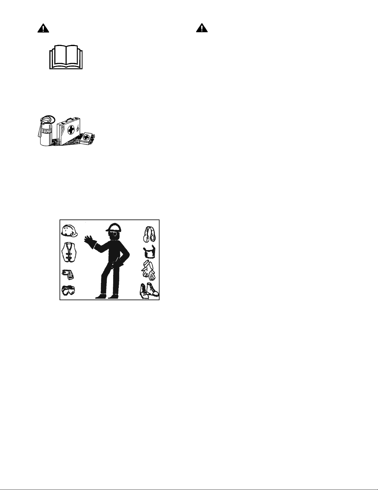
6. Wear appropriate protective devices as instructed on the chemical or fertilizer MSDS.
1. Read and understand Operator’s Manual and all safety signs before using.
2. Lower machine to ground, place all controls in
neutral, stop engine, set park brake, remove ignition key, and wait for all moving parts to stop
before servicing, adjusting, repairing or unplugging.
3. Install and secure all guards and shields before starting or operating.
4. Keep hands, feet, hair and clothing away from all moving and/or rotating parts.
5. Do not allow riders on applicator or tractor during operation or transporting.
6. Clear area of all bystanders, especially children, before starting or filling with chemical or fertilizer.
7. Read chemical or fertilizer manufacturers warnings, instructions and procedures before starting
and follow them exactly.
7. Lower machine to ground, place all controls in
neutral, stop engine, set park brake, remove ignition key, and wait for all moving parts to stop
before servicing, adjusting, repairing or unplugging.
8. Read chemical manufacturers warnings, instructions and procedures before starting and follow
them exactly.
9. Post Poison Control Emergency telephone number for your area on applicator before using Agricultural chemicals.
Have container label handy when seeking medical
attention.
8. Do not breathe, touch or ingest chemicals or fertilizer. Always wear protective clothing and follow
safe handling procedures.
9. Stay away from wings when folding or extending wings. Keep others away.
10. Clean reflectors, SMV and lights before transporting.
11. Attach securely to towing unit using a hardened pin with a retainer and a safety chain.
12. Do not exceed a safe travel speed.
13. Use hazard flasher on tractor and applicator when transporting.
14. Stay away from overhead power lines when folding or extending wings and during transport.
15. Before applying pressure to hydraulic system, make sure all components are tight, hoses and couplings are in good condition.
16. Review safety instructions annually.
10. Review safety related items with all personnel annually.
8300 Liquid Fertilizer Applicator 9 FAST AG Solutions
Page 11
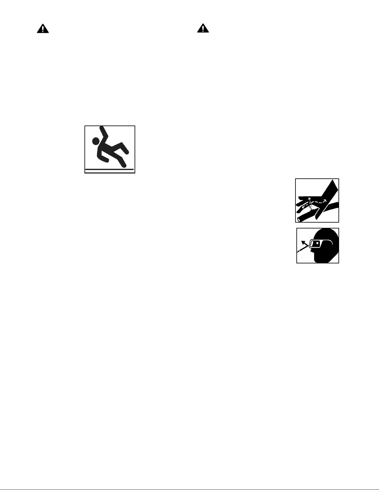
2.4 Maintenance Safety
2.5 Hydraulic Safety
1. Review Operator’s Manual and all safety items before working with, maintaining or operating applicator.
2. Lower machine to ground, place all controls in
neutral, stop engine, set park brake, remove ignition key, and wait for all moving parts to stop
before servicing, adjusting, repairing or unplugging.
3. Follow good shop practices:
4. Keep service area clean and dry.
5. Be sure electrical outlets and tools are properly grounded.
6. Use adequate light for job at hand.
7. Before applying pressure to a hydraulic system, make sure all components are tight, hoses and couplings are in good condition.
8. Relieve pressure from hydraulic circuit before servicing or disconnecting from tractor.
1. Always place all tractor hydraulic controls in neutral before dismounting.
2. Make sure that all components in hydraulic system are kept in good condition and are clean.
3. Replace any worn, cut, abraded, flattened or crimped hoses.
4. Do not attempt any makeshift repairs to hydraulic lines, fittings or hoses by using tape, clamps or cements.
5. The hydraulic system operates under extremely high-pressure. Such repairs will fail suddenly and create a hazardous and unsafe condition.
6. Pressurized fluids can penetrate the skin. Hydraulic
hoses can fail from age, damage and exposure.
7. Do not search for hydraulic leaks without body and face protection. A tiny, almost invisible leak can penetrate the skin, thereby requiring immediate medical attention. Use wood or cardboard to detect hydraulic leaks, never use your hands.
9. Keep hands, feet, clothing and hair away from all moving and/or rotating parts.
10. Clear area of bystanders, especially children, when carrying out any maintenance and repairs or making any adjustments or filling.
11. Place stands or blocks under frame before working beneath machine or when changing tires.
12. Be sure all guards are in place and secured when maintenance work is completed.
13. Use only tools, jacks and hoists of sufficient capacity for the job.
8. If injured by a concentrated
high-pressure stream of hydraulic fluid, seek medical attention immediately. Serious infection or
toxic reaction can develop from hydraulic fluid
piercing skin surface.
9. Before applying pressure to system, verify all components are tight, hoses and couplings are in good condition.
8300 Liquid Fertilizer Applicator 10 FAST AG Solutions
Page 12

2.6 Transport Safety
1. Read and understand ALL information in Operator’s Manual regarding procedures and SAFETY
when operating applicator in field and/or on road.
2. Check with local authorities regarding applicator transport on public roads. Obey all applicable laws and regulations.
NOTICE
Prevent equipment damage.
Verify main tank is empty before
transporting on road.
3. Always travel at a safe speed. Use caution when making corners or meeting traffic.
4. Make sure the SMV (Slow Moving Vehicle) emblem and all lights and reflectors that are required by the local highway and transport authorities are in place, are clean and can be seen clearly by all overtaking and oncoming traffic.
13. Post Poison Control Emergency telephone number for your area on applicator before using Agricultural chemicals.
14. Have container label handy when seeking medical attention.
15. Review safety related items with all personnel annually.
5. Daybreak and dusk are particularly dangerous and pilot vehicles are recommended.
6. Be sure applicator is properly connected to towing vehicle and a retainer is used through drawbar pin. Always attach a safety chain between frame and towing vehicle.
7. Keep right and yield right-of-way to allow faster traffic to pass. Drive on road shoulder, if permitted by law.
8. Do not exceed 20 mph (32 km/h). Reduce speed on rough roads and surfaces.
9. Always use hazard warning flashers on tractor when transporting unless prohibited by law.
10. Stay away from overhead power lines during transport. Electrocution can occur without direct contact.
11. Lower machine to ground, place all controls in
neutral, stop engine, set park brake, remove ignition key, and wait for all moving parts to stop
before servicing, adjusting, repairing or unplugging.
12. Read chemical manufacturers warnings, instructions and procedures before starting and follow
them exactly.
8300 Liquid Fertilizer Applicator 11 FAST AG Solutions
Page 13

2.7 Storage Safety
2.9 Safety Signs
1. Store unit in an area away from human activity.
2. Do not permit children to play on or around the stored applicator.
2.8 Tire Safety
1. Failure to follow proper procedures when mounting a tire on a wheel or rim can produce an explosion which may result in serious injury or death.
2. Do not attempt to mount a tire unless you have the proper equipment and experience to do the job.
3. Have a qualified tire dealer or repair service perform required tire maintenance.
1. Keep safety signs clean and legible at all times.
2. Replace safety signs that are missing or have become illegible.
3. Replaced parts that displayed a safety sign should also display the current sign.
4. Safety signs are available from your Distributor or the factory.
5. How to Install Safety Signs:
• Be sure that the installation area is clean and
dry.
• Be sure temperature is above 50°F (10°C).
• Decide on exact position before you remove
backing paper.
• Remove the smallest portion of the split backing
paper.
• Align the sign over the specified area and care-
fully press the small portion with the exposed
sticky backing in place.
• Slowly peel back the remaining paper and care-
fully smooth the remaining portion of the sign in
place.
• Small air pockets can be pierced with a pin and
smoothed out using the piece of sign backing
paper.
8300 Liquid Fertilizer Applicator 12 FAST AG Solutions
Page 14

2.10 Sign-Off Form
FAST AG Solutions follows the general Safety Standards specified by the American Society of Agricultural
Engineers (ASAE) and the Occupational Safety and Health Administration (OSHA). Anyone who will be operating
and/or maintaining the FAST AG Solutions Liquid Fertilizer Applicator must read and clearly understand ALL
Safety, Operating and Maintenance information presented in this manual.
Do not operate or allow anyone else to operate this equipment until such information has been reviewed.
Annually review this information before season start-up.
A sign-off sheet is provided for your record keeping to show that all personnel who will be working with the equipment have read and understand the information in the Operator’s Manual and have been instructed in the operation of the equipment.
Sign Off Form
DATE EMPLOYEE SIGNITURE EMPLOYER SIGNITURE
8300 Liquid Fertilizer Applicator 13 FAST AG Solutions
Page 15
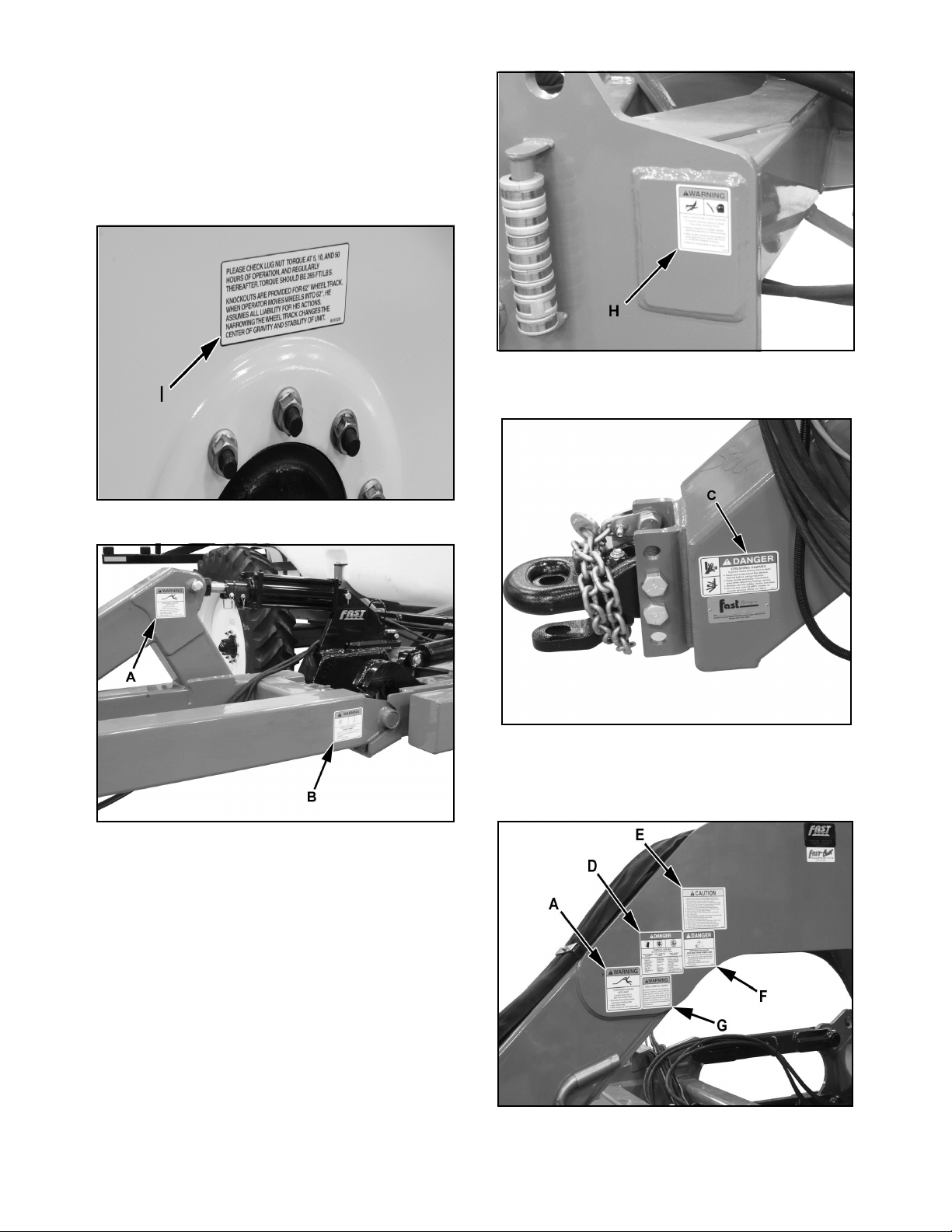
2.11 Safety Sign Locations
Safety signs and locations on machine are shown in
the following illustrations. Familiarize yourself with
safety signs, type of warning and area, or particular
function related to that area, that requires your
SAFETY AWARENESS.
8300 Liquid Fertilizer Applicator 14 FAST AG Solutions
Page 16
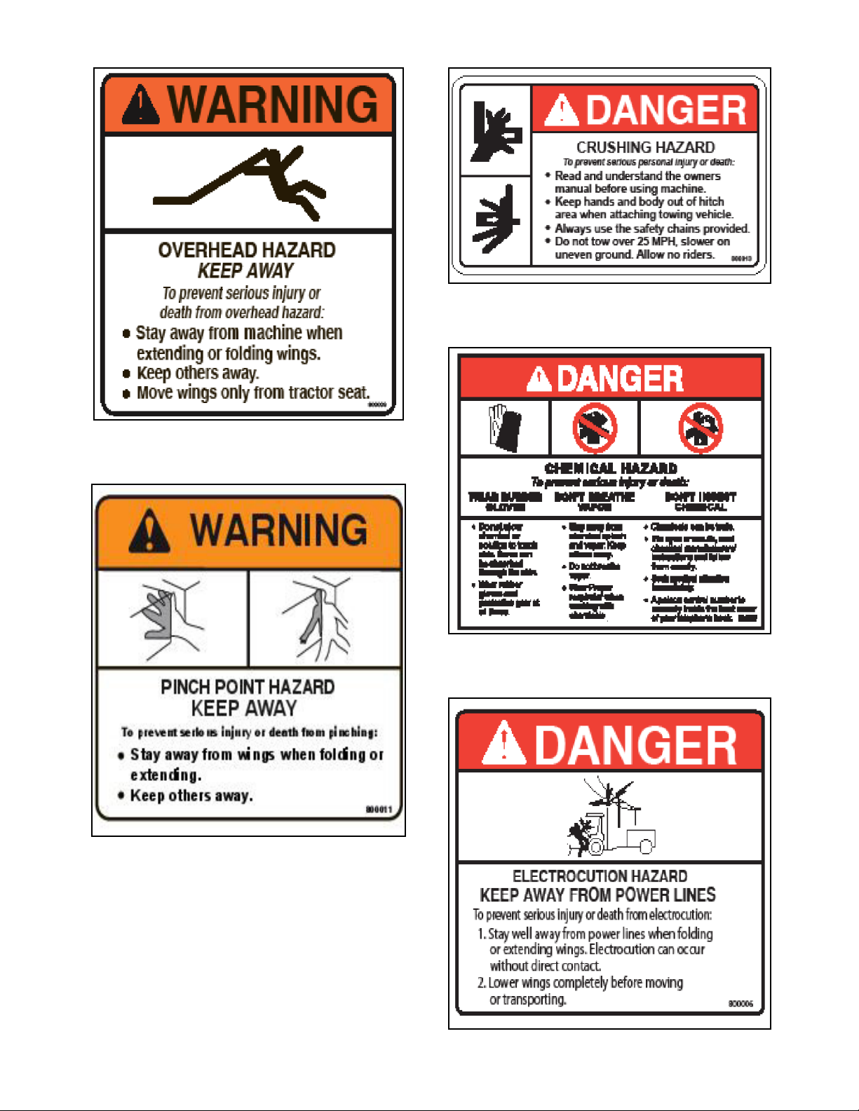
DECAL A
DECAL C
DECAL D
DECAL B
DECAL E
8300 Liquid Fertilizer Applicator 15 FAST AG Solutions
Page 17
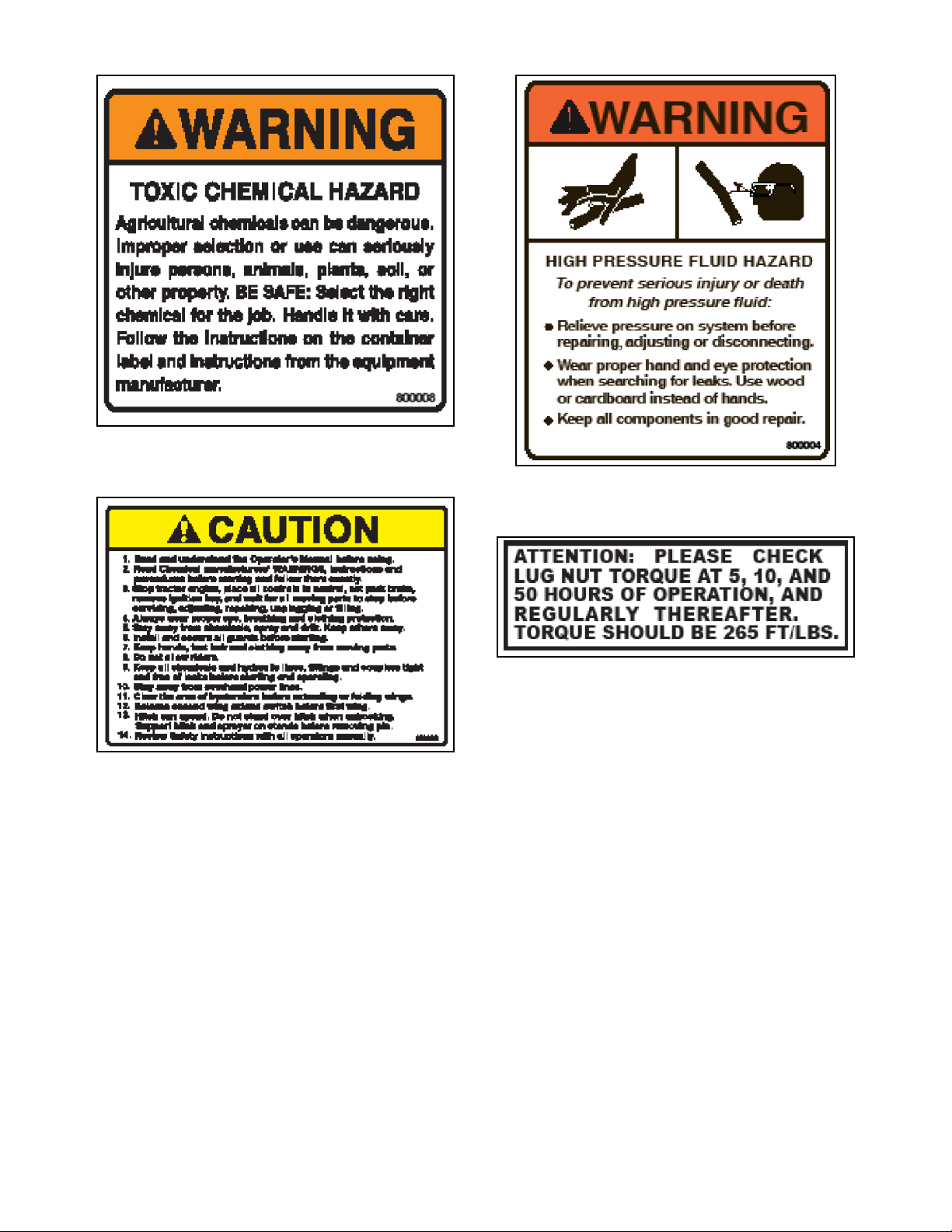
DECAL F
DECAL G
DECAL H
DECAL I
8300 Liquid Fertilizer Applicator 16 FAST AG Solutions
Page 18
3. Operation
Read and understand Operator’s Manual and all
safety signs before using.
Stay away from overhead power lines when
folding or extending the wings and during
transport.
Lower machine to the ground, place all controls
in neutral, stop engine, set park brake, remove
ignition key, and wait for all moving parts to
stop before servicing, adjusting, repairing or
unplugging.
Install and secure all guards and shields before
starting or operating.
Keep hands, feet, hair and clothing away from
all moving and/or rotating parts.
Do not allow riders on the applicator or tractor
during operation or transporting.
Clear area of all bystanders, especially
children, before starting or filling with chemical
or fertilizer.
Before applying pressure to the hydraulic
system, make sure all components are tight,
hoses and couplings are in good condition.
Review safety instructions before operating
machine.
3.1 New Operator Or Owner
The FAST AG Solutions Liquid Fertilizer Applicator is
designed to meter out and distribute liquid chemical or
fertilizer and place it where required.
It is the responsibility of the owner or operator to read
this manual and to train all other operators before they
start working with the machine. Follow all safety
instructions exactly. Safety is everyone’s business. By
following recommended procedures, a safe working
environment is provided for the operator, bystanders
and the area around the work site. Untrained
operators are not qualified to operate the machine.
Read chemical or fertilizer manufacturers
warnings, instructions and procedures before
starting and follow them exactly.
Do not breathe, touch or ingest chemicals or
fertilizer. Always wear protective clothing and
follow safe handling procedures.
Stay away from wings when folding or
extending wings. Keep others away.
Clean reflectors, SMV and lights before
transporting.
Attach securely to towing unit using a hardened
pin with a retainer and a safety chain.
Do not exceed a safe travel speed.
Many features incorporated into this machine are the
result of suggestions made by customers like you.
Read this manual carefully to learn how to operate the
machine safely and how to set it to provide maximum
field efficiency. By following the operating instructions
in conjunction with a good maintenance program, your
applicator will provide many years of trouble-free
service.
Use hazard flasher on tractor when
transporting.
8300 Liquid Fertilizer Applicator 17 FAST AG Solutions
Page 19
3.2 Machine Components
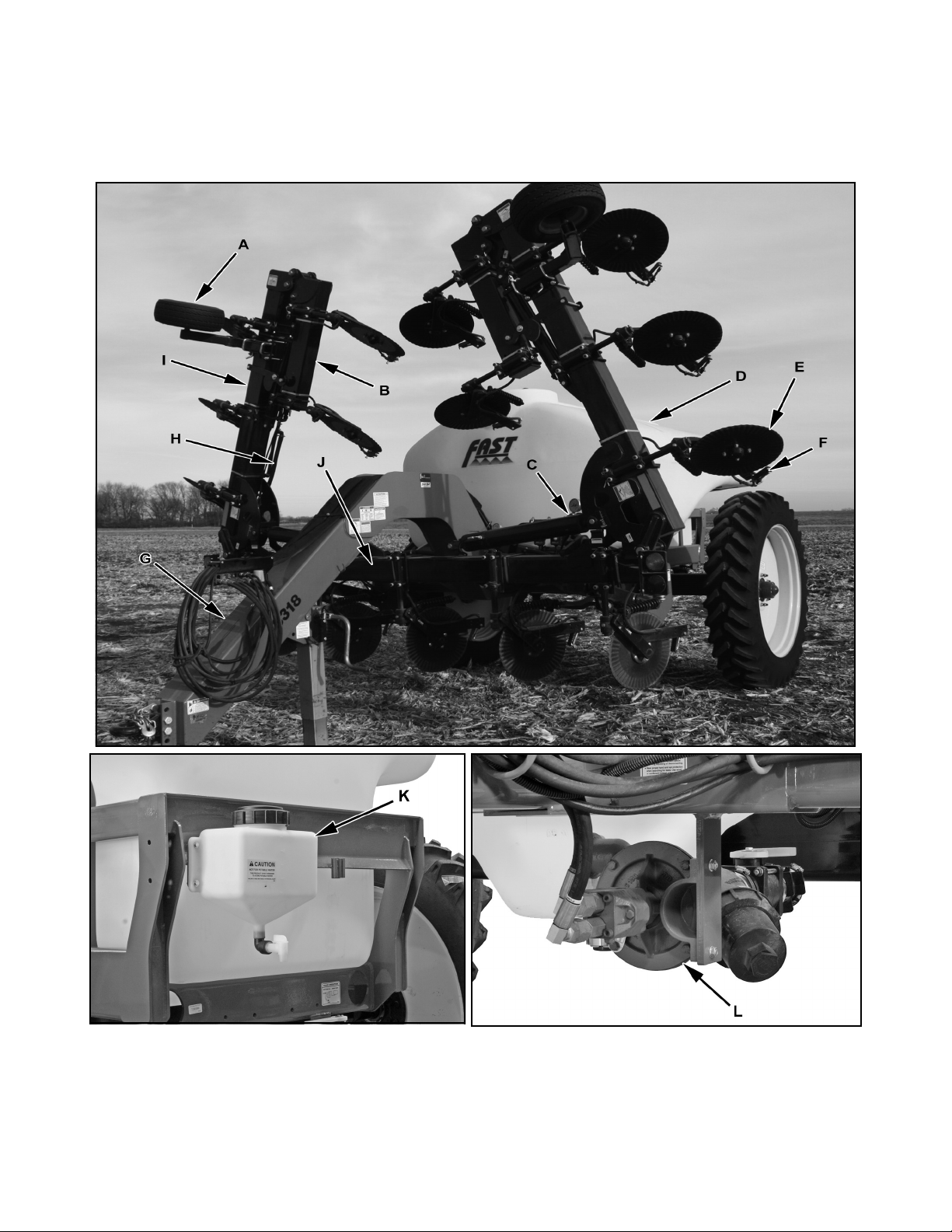
The FAST AG Solutions Liquid Fertilizer Applicator has a hydraulic powered metering pump to send liquid
chemicals or fertilizer to the distribution lines on the tool bar. Coulters open the soil to receive the liquid. Nozzles
mounted to the tool bar spray the fluid into the soil.
A - Gauge Wheel
B - Outer Wing
C - Flow Control
D - Tank
E - Coulter
F - Nozzle
8300 Liquid Fertilizer Applicator 18 FAST AG Solutions
G - Hitch
H - Liquid Line
I - Inner Wing
J - Center Frame
K - Rinse Tank
L - Pump
Page 20

3.3 Break-In
3.4 Pre-Operation Checklist
Perform the following steps on a new applicator:
After 1 hour of operation:
1. Tighten all wheel lugs to 265 lb/ft of torque.
2. Tighten all other fasteners and hardware to required torque.
3. Check that no chemical or hydraulic lines are being pinched or crimped. Re-route as required.
4. Check that all coulters, nozzles and placement components are clean and working properly. Clean as required.
5. Check that metering pump is functioning properly. Adjust as required.
6. Lubricate all grease fittings.
After 5 hours of operation:
1. Tighten all wheel lugs to 265 lb/ft of torque.
After 10 hours of operation:
1. Tighten all fasteners and hardware to required torque.
2. Check chemical and hydraulic line routing.
3. Check that all placement components are clean and working properly.
After 50 hours of operation:
1. Tighten all wheel lugs to 265 lb/ft of torque.
2. Then follow normal servicing and maintenance schedule as defined in Maintenance Section.
Efficient and safe operation of the FAST AG Solutions
Liquid Fertilizer Applicator requires that each operator
reads and understands operating procedures and all
related safety precautions outlined in this section. A
pre-operational checklist is provided for the operator.
It is important for both personal safety and maintaining
the good mechanical condition of the applicator that
this checklist be followed.
Before operating applicator, check the following items:
1. Lubricate machine per schedule outlined in “Maintenance Section”.
2. Use only a tractor of adequate power and weight
to operate applicator. See Section 3.5.1 for recommendations.
3. Be sure that machine is properly attached to tractor. Be sure that a mechanical retainer is installed
through drawbar pin and safety chain is installed.
4. Inspect all hydraulic lines, hoses, fittings and couplers for tightness.
5. Check tires and verify they are inflated to specified pressure.
6. Calibrate applicator if at start of season or a new applicator rate is being used.
7. Check condition and routing of all fluid hoses and lines. Be sure that all lines are routed in large arcs. Replace any that are damaged. Re-route those that are rubbing, pinched or crimped.
8. Check placement components. Remove and replace any that are worn.
9. Remove all entangled material.
10. Raise tool bar and turn metering pump slightly.
Check that there is liquid coming out of each nozzle. Unplug or connect lines as required. Replace
any nozzles that are plugged.
8300 Liquid Fertilizer Applicator 19 FAST AG Solutions
Page 21
3.5 Equipment Matching
3.6 Controls
To insure the safe and reliable operation of the
applicator, it is necessary to use a tractor with
appropriate specifications. As a guideline, insure that
these requirements are met:
1. Tractor Horsepower: Refer to table below minimum recommended horsepower for your machine. Although recommended tractor horsepower is not required to pull machine, it does provide required strength in drawbar as hitch is very heavy. This will also insure that the unit has the required stability and control in hilly terrain and during transport.
Model Width Horsepower
8310, 8313 30 110
40 130
8318, 8324 30 130
40 150
2. Front End Weights: By following recommendations for tractor power, tractor will have sufficient weight to provide stability during field operation or when transporting. It is also recommended that each tractor be equipped with a full compliment of suitcase weights on front of tractor. This will provide the required weight on front for turning and extra traction if equipped with front wheel assist.
3. Hydraulic System: Tractor hydraulic system must be capable of 8 gpm (24 lpm) at 2000 psi (13,800 kPa) to operate lift cylinders and drive motor. Either closed center or open-centered systems can be used. However an open centered hydraulic system is limited to 8 gpm maximum.
It is recommended that all operators review this
section of manual and metering pump manual to
familiarize themselves with location and function of all
machine controls and settings before starting.
1. Metering Pump:
•An Operator’s Manual is supplied with machine.
Review manual carefully to determine required
hydraulic setting on pump for your application.
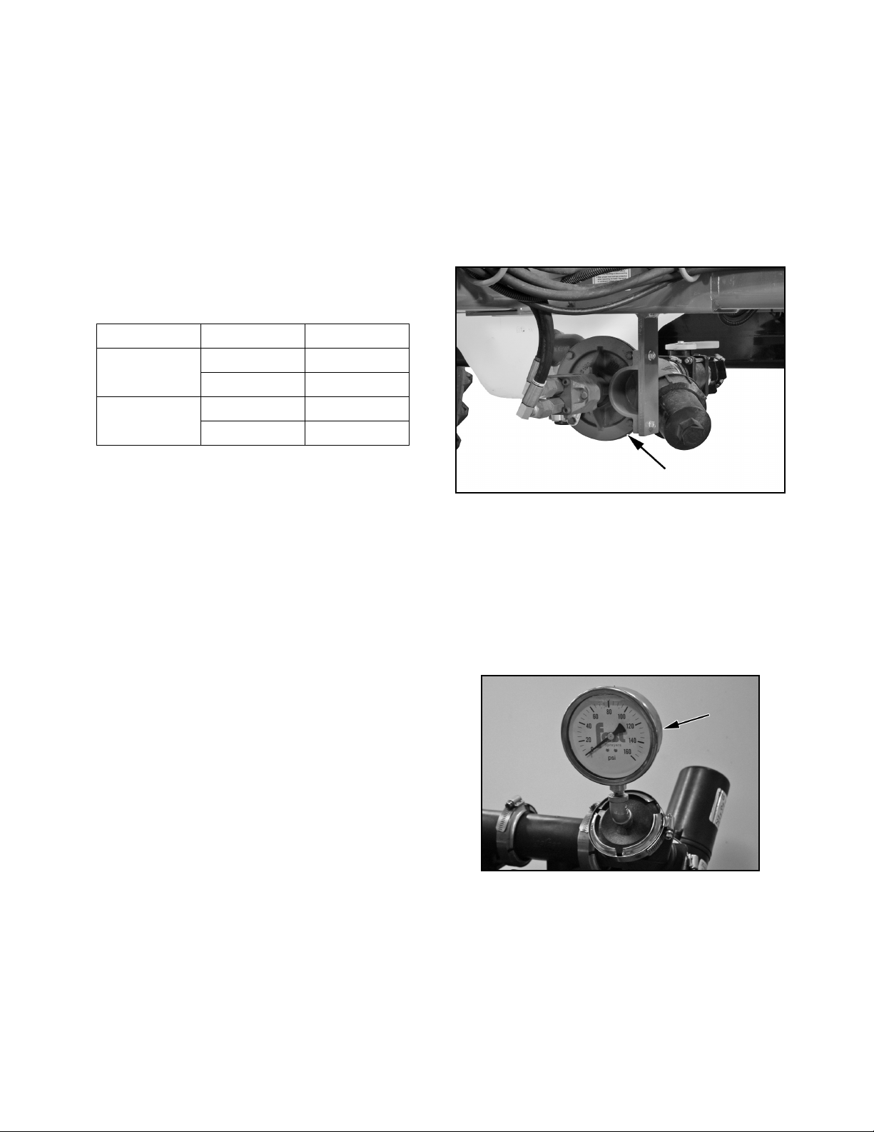
2. Liquid System Pressure Gauge:
•This gauge monitors pressure in liquid circuit providing flow to injector orifices. It is normally used
to determine pressure in chemical/fertilizer circuit
when setting system for a specific application rate.
Monitor gauge during operation. Stop and check
system if pressure changes suddenly
.
Note: Contact factory for an optional flow
control for use with high flow open center
system.
Four remote outlets are required to operate the
applicator.
1. Tool bar lift cylinders and wing kick.
2. Inner wing extend/fold cylinders.
3. Outer wing extend/fold cylinders
4. Chemical / fertilizer pump drive motor.
Note: Always place hydraulic control lever
in detent to provide a constant flow of oil
to pump drive motor.
8300 Liquid Fertilizer Applicator 20 FAST AG Solutions
Page 22
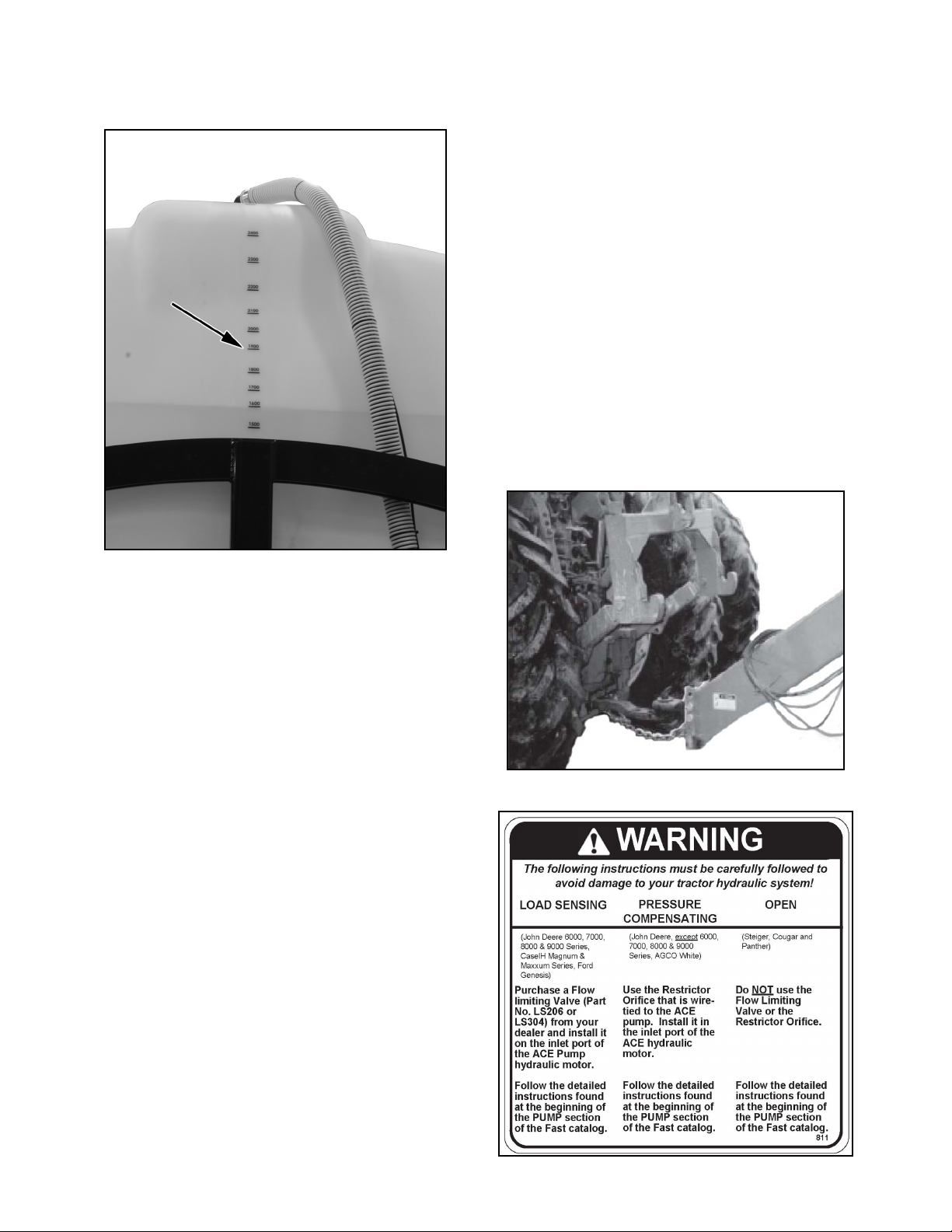
3. Tank Scale:
•The back end of tank has a capacity scale
molded into it to assist operator when filling tank.
3.7 Attaching/Unhooking Tractor
1. Make sure that all bystanders are clear of working area.
2. Make sure there is enough room and clearance to safely back up to machine.
3. Slowly back tractor until holes on hitch and drawbar are aligned.
4. Install drawbar pin and retainer.
5. Attach safety chain securely around tractor drawbar cage to prevent unexpected separation.
6. Check that applicator hydraulic system is compatible with tractor hydraulics. Change applicator if
required. Do not operate unless tractor and applicator hydraulics are compatible.
4. Automatic Controller (Optional):
•This optional automatic controller will monitor, set
and control the operation of the applicator. Refer
to the operators manuals supplied with the controller for detailed instructions.
8300 Liquid Fertilizer Applicator 21 FAST AG Solutions
Page 23
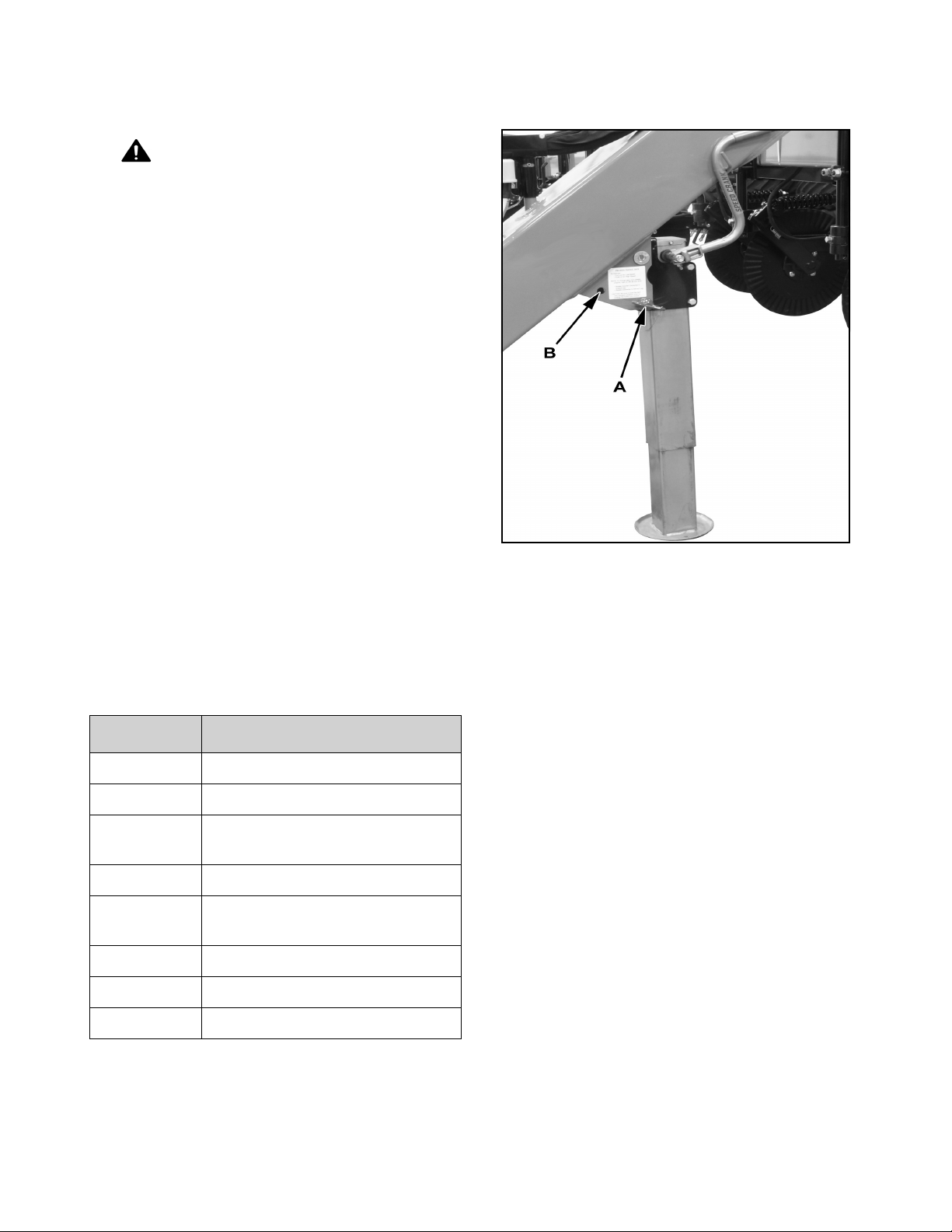
7. Connect hydraulics:
•a. Use a clean rag or paper towel to clean dirt
from couplers on hose ends and tractor couplers.
WARNING
Prevent serious injury or death.
Relieve hydraulic system pressure before
connecting hydraulic hoses.
Relieve pressure in hydraulic system.
Route hoses over hitch and connect
hoses to tractor couplers. Verify couplers
are securely seated. Be sure to provide
slack for turning.
•SCV1: Connected to tool bar lift cylinders and
wing kick.
•SCV2: Connected to inner wing extend/fold cylinders.
9. Turn crank handle to raise jack. Pull pin (A) out
and pivot jack frame forward into its stowed position. Insert pin in hole (B) to secure jack.
•SCV3: Connected to outer wing extend/fold cylinders.
•SCV4: Connected to hydraulic pump.
Table 1: HYDRAULIC HOSE KEY
COLOR DESCRIPTION OF USE
Red Pump Pressure
Yellow Pump Return
Blue Main Fold Pressure (Lower) - run
in constant flow
Green Main Fold Return (Raise)
Gray Main Lift /Wing Kick Pressure
(Lower)
Orange Main Lift /Wing Kick Return (Raise)
Purple Flip Fold Pressure (Lower)
Brown Flip Fold Return (Raise)
10. Reverse procedure when unhooking.
3.8 Machine Setting
Applicator is equipped with a pump that meters out a
quantity of fluid and sends it through distribution line to
nozzles mounted along the tool bar. The pump can be
set to give a wide range of application rates.
Always be aware of the size of the field to be covered,
the application rate and the amount of liquid in the
tank. If there is liquid left over or you run short, check
the application rate. Reset if required or verify tank
volume.
Always check that liquid comes out of each nozzle at
the start of the season and each day by engaging the
hydraulic circuit momentarily. A nozzle that does not
work properly will skew your application efficiency.
8. Route electrical lines over hitch and connect to tractor electrical connectors. Be sure to provide slack for turning.
8300 Liquid Fertilizer Applicator 22 FAST AG Solutions
Page 24
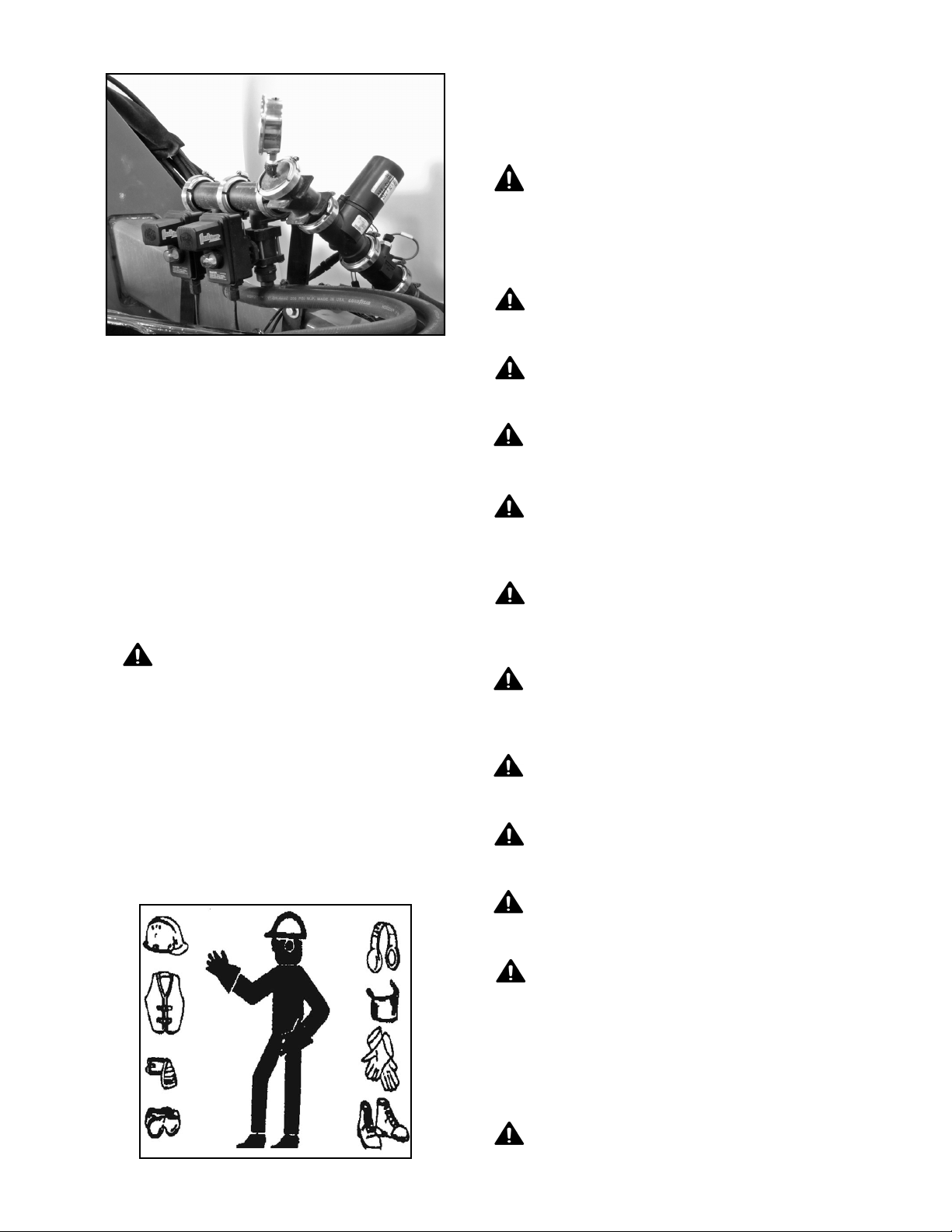
3.9 Field Operation
Read and understand Operator’s Manual and all
safety signs before using.
Lower machine to the ground, place all controls
in neutral, stop engine, set park brake, remove
ignition key, and wait for all moving parts to
stop before servicing, adjusting, repairing or
unplugging.
Install and secure all guards and shields before
starting or operating.
Your machine is equipped with automatic controller.
Review controller manual to become familiar with
applicator settings and control.
Optional Wheel Speed Sensor
Verify speed sensor on left wheel hub is set with a gap
of 1/8 inch (3mm) or the thickness of a nickel. Sensor
supplies a signal to controller for determining ground
speed and allows controller to vary application rate
appropriate for speed.
WARNING
Prevent serious injury or death.
Check chemical or fertilizer MSDS for
proper handling instructions.
Toxic chemicals can enter the body by
breathing, spray or contact with bare skin.
Do not take a chance with your health and
safety.
Keep hands, feet, hair and clothing away from
all moving and/or rotating parts.
Do not allow riders on the applicator or tractor
during operation or transporting.
Clear area of all bystanders, especially
children, before starting or filling with chemical
or fertilizer.
Read chemical or fertilizer manufacturers
warnings, instructions and procedures before
starting and follow them exactly.
Do not breathe, touch or ingest chemicals or
fertilizer. Always wear protective clothing and
follow safe handling procedures.
Stay away from wings when folding or
extending wings. Keep others away.
Clean reflectors, SMV and lights before
transporting.
Attach securely to towing unit using a hardened
pin with a retainer and a safety chain.
Do not exceed a safe travel speed.
NOTICE
Prevent Damage To Equipment
Verify main tank is empty before
transporting on road.
Use hazard flasher on tractor.
8300 Liquid Fertilizer Applicator 23 FAST AG Solutions
Page 25
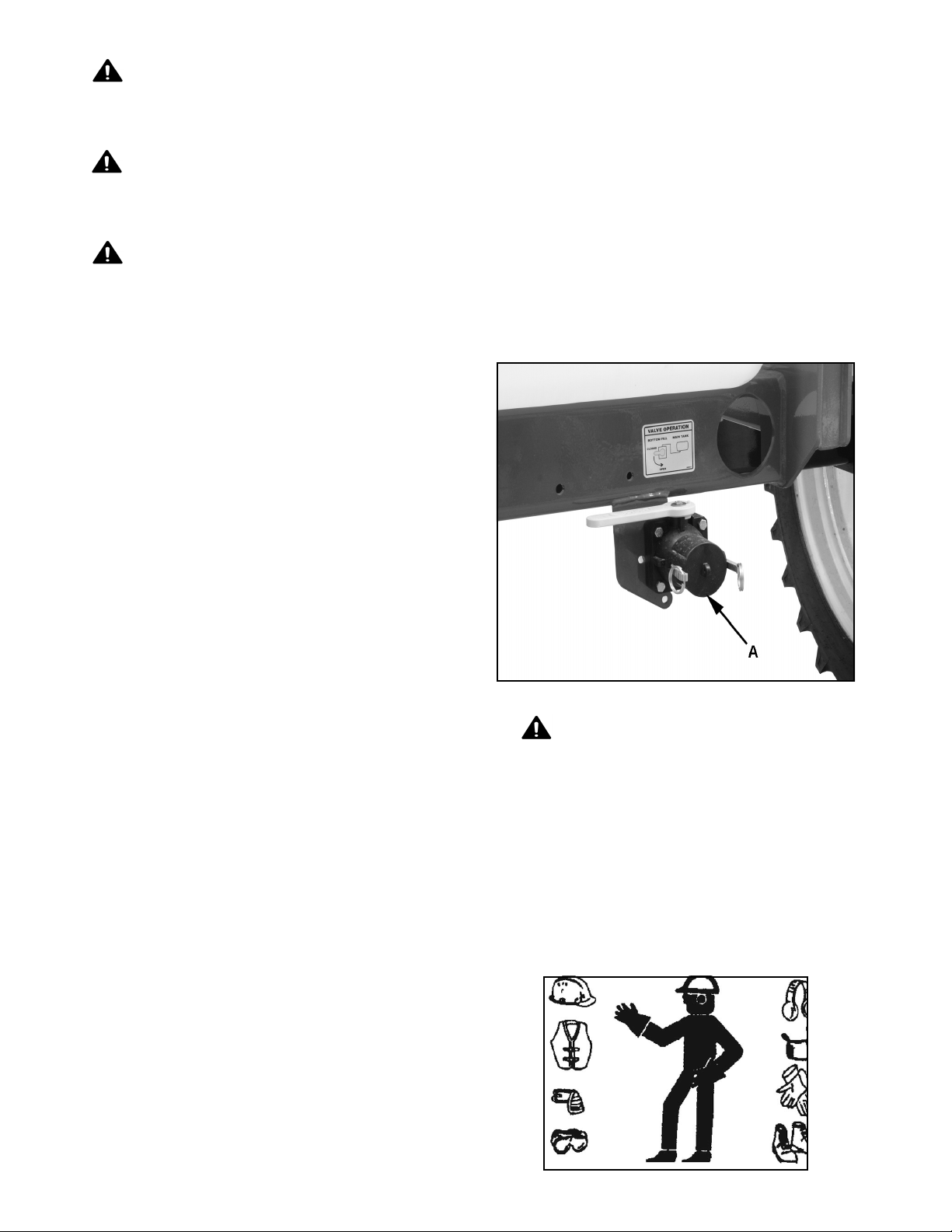
Stay away from overhead power lines when
folding or extending the wings and during
transport.
10. Filling: It is recommended that machine be transported to
the field empty and filled in the field.
Before applying pressure to the hydraulic
system, make sure all components are tight and
that hoses and couplings are in good condition.
Review safety instructions before operating
machine.
Set machine and desired application rate for operating
conditions. Time spent setting machine and
application rate before starting will result in a quality
job.
1. Attach applicator to machine (see Section 3.8).
2. Review and follow pre-operation checklist.
3. Read and follow chemical/fertilizer manufacturers’ instructions.
4. Set applicator so you know exactly how much liquid is being applied (see Section 3.8). Incorrect
application rates can dramatically affect seed germination and yields. Set at start of season or when
changing application rate.
•To fill tank:
•Pull up to tender truck or drive truck to machine.
•Connect transfer hose to bottom fill line (A).
•Start pump on tender truck and open valve on
input line.
•Pump until tank is filled to desired level. Do not
over-fill.
•Close input valve and stop pump on tender
truck.
•Remove and stow fill line.
•Install and fasten input line covers
5. Transport machine to working area.
6. Open machine to field position (see Step 14).
7. Starting:
•Set engine RPM at rated speed.
•Place hydraulic motor control lever in detent.
•Start into field.
•Lower the tool bar into ground.
•Turn on boom sections
8. Stopping:
•Turn off boom sections
•Place hydraulic motor control lever in float position and lift tool bar out of ground.
•Stop forward motion of machine, place hydraulic
lever in its off position
•Reduce engine RPM to low idle.
9. Emergency stop:
•If an emergency arises, shut engine off to stop
machine or stop forward motion. Refer to Step 7
when restarting the machine.
WARNING
Prevent serious injury or death.
Check chemical or fertilizer MSDS for
proper handling instructions.
Toxic chemicals can enter the body by
breathing, spray or contact with bare skin.
Do not take a chance with your health and
safety.
8300 Liquid Fertilizer Applicator 24 FAST AG Solutions
Page 26
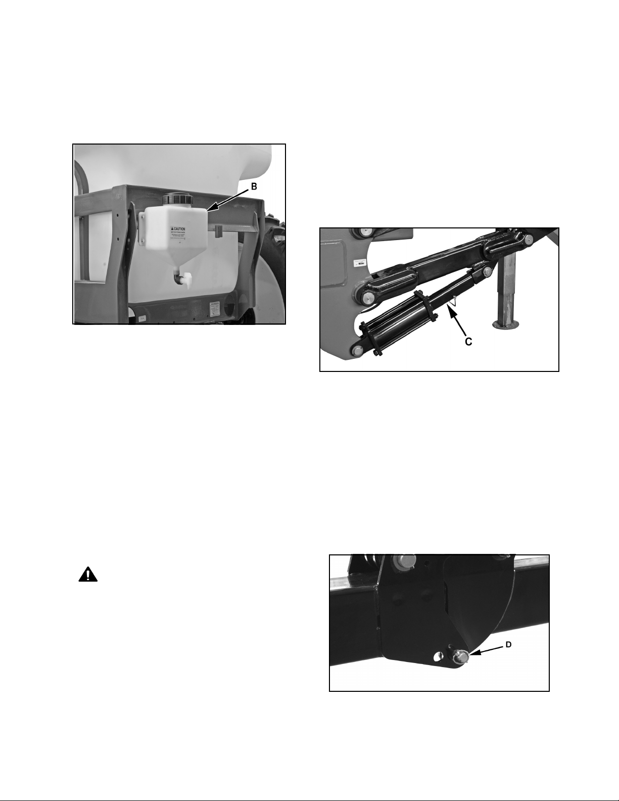
11. Fresh Water Rinse Tank:
•Each machine is equipped with a fresh water
rinse tank (B) on rear frame.
•Fill rinse tank with clean fresh water whenever
rinse water has been used. Do not allow tank to
run low on fresh water.
•Use water from rinse tank to clean, rinse or wash
anything that has become contaminated.
NOTICE
Prevent wing rest damage.
Never engage tractor remote lever to
lower center section (orange labeled hose)
while main wings are in transport position.
•Engage tractor remote #1 to raise main lift and
main wing kick cylinders to the fully raised position.
•Remove transport brace (C) from main lift cylinders.
12. Ground speed:
•It will be necessary to establish travel speed and
then set flow to give desired application rate.
•Always run at established travel speed.
•Best results are obtained when ground speed is 5
- 8 mph.
•Ground speed variations in the field will automatically be compensated.
•Always operate at a comfortable speeds.
•Do not operate so fast that tool bar or tank
bounce while going through the field. Effective
results require that liquid be applied at a consistent depth in a consistent manner. Machine
bouncing will prevent this required consistency.
13. Unfolding/Extending Tool Bar:
•Verify tool bar is fully raised.
WARNING
Prevent serious injury or death.
Machine coming near or contacting power
lines can cause electrocution.
•Remove safety pin from main wing hinge on both
sides.
•Engage tractor remote #2 to unfold main wings
from the saddled transport position. When main
wings are fully unfolded, they will remain “kicked”
up until center section is lowered during field operation.
•Engage tractor remote #3 to unfold outer flip
wings to the field position.
Electrocution can occur without contact.
Fully lower wings before moving or
transporting.
8300 Liquid Fertilizer Applicator 25 FAST AG Solutions
•Insert flip wing lock pin (D) into holes to lock flip
wing in field position.
Page 27
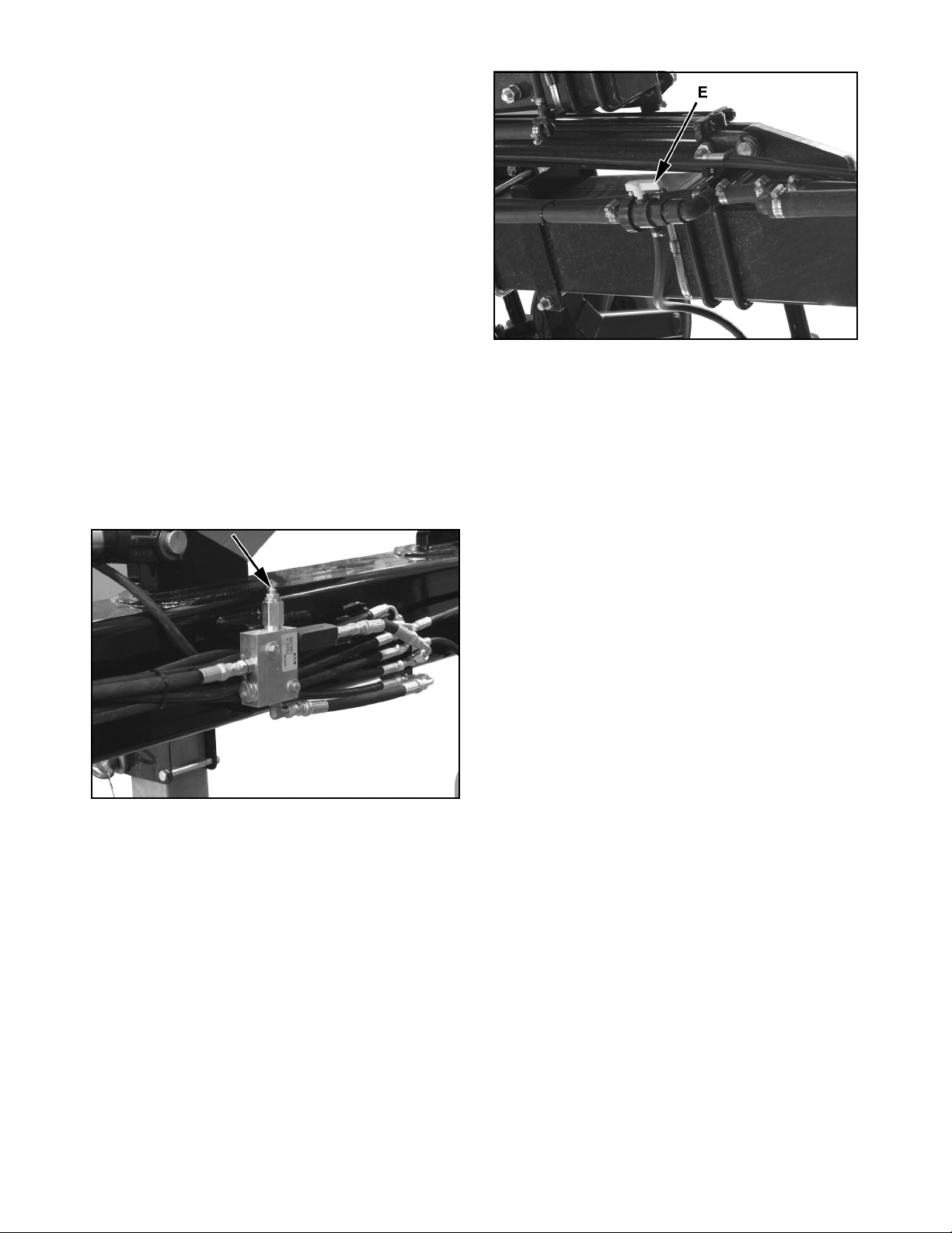
•Toolbar is now in position to begin field application.
•Check amount of down pressure applied to
main wings by engaging remote #2 continuously
and lowering coulters into the ground while
remaining stationary with unit. Hydraulic down
pressure gauge should read between 700 and
1500 psi. Down pressure may be adjusted by
turning socket head screw on down pressure
valve located on toolbar near wing fold manifold.
•Use only as much down pressure as needed to
get coulters to proper depth. Excess pressure
could cause damage to toolbar. Turn socket
head screw clockwise to increase pressure and
turn counter clockwise to decrease down pressure. To change pressure, loosen jam nut, turn
adjustment stem a 1/4 turn at a time. Do not
exceed 1500 PSI.
•Reverse the tractor remote #1 to fully raise toolbar and kick wings up. Toolbar is now ready for
field application.
15. Application Depth:
•Depth of material placement can vary depending
on type of application. Check with fertilizer or
chemical manufacturer for information regarding
application depth. Set tool bar, coulter or nozzle to
required depth.
•Once desired field location of application is
reached, center section and main wing kick may
be lowered by engaging the tractor remote #1.
Even after coulters are in ground, tractor remote
#1 must be constantly engaged providing oil supply to and from down pressure circuit.
14. Outer Wing Valve - 40 Ft Machines: Chemical lines to outer wings have a valve to shut
off flow to nozzles on flip wing. Turn valves (E) off
to get a 30 ft. application width. Open valves when
30 ft. requirements are finished. Right wing valve
illustrated.
•Failure to keep tractor remote #1 engaged and
supply a constant oil flow to down pressure system will result in coulter riding out of the ground,
and could result in structural failure of the toolbar
and/or hydraulic cylinder components.
8300 Liquid Fertilizer Applicator 26 FAST AG Solutions
Page 28
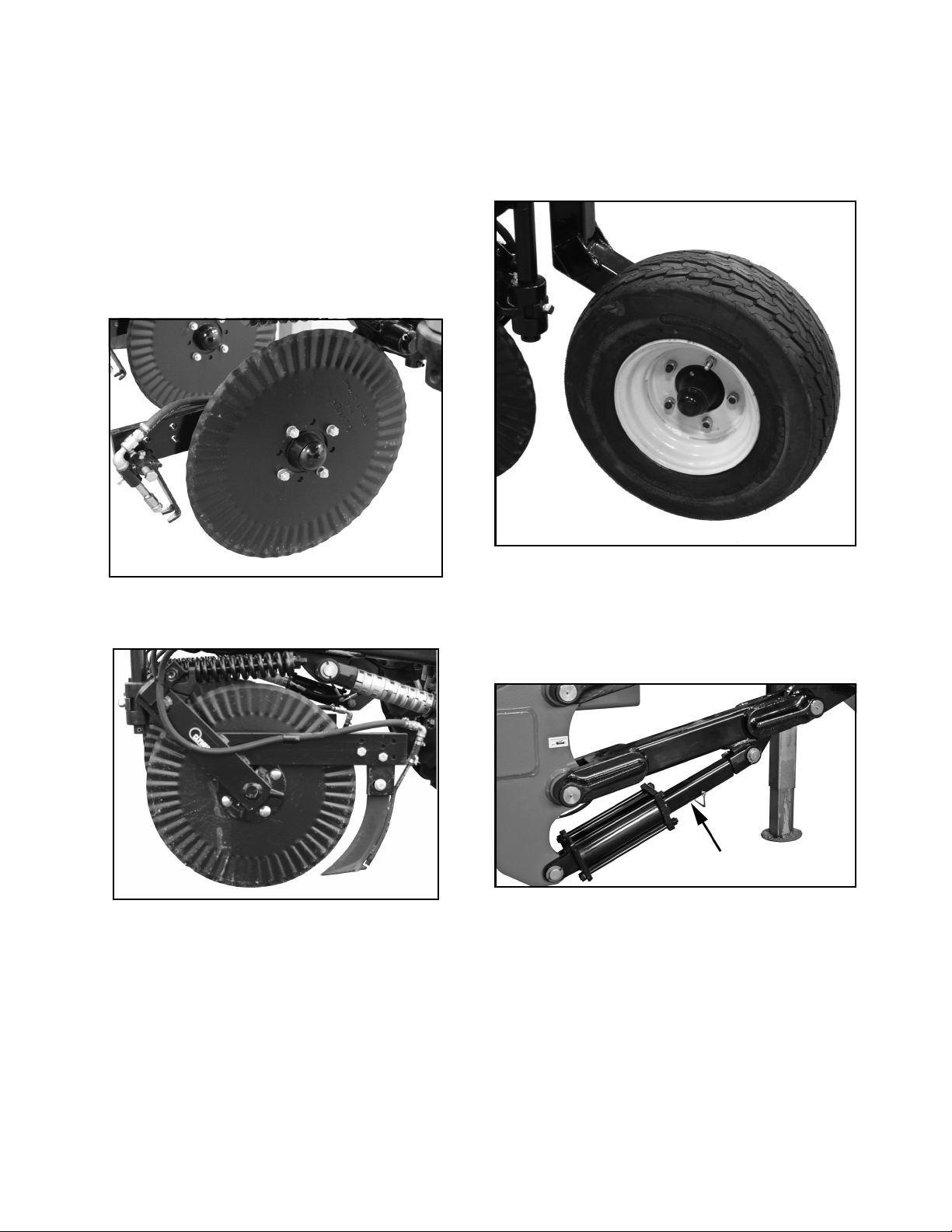
16. Coulters: Coulters are used to cut crop residue on surface,
penetrate ground and part the soil to accept liquid
from nozzle. Coulter depth is controlled by
spacers on lift cylinder ram and gauge wheel
position.
Inspect coulters frequently if operating in rocky
conditions. Bent, chipped or broken coulters will
not penetrate soil properly. Always remove
entangled material from any component.
17. Gauge Wheels: Each inner wing and flip wing is equipped with a
gauge wheel that helps to maintain application
depth. Lower gauge wheels if soil conditions are
soft and raise if hard to obtain the same
application depth.
Coulter With Injector Nozzle
Coulter With Knife
18. Depth Control: Install spacers on tool bar lift cylinder ram to give
required machine depth. Tool bar can then be fully
lowered and always return to same depth.
19. Nozzles / Knives: Refer to TeeJet’s nozzle/orifice application rate
table to determine correct of tip or orifice.
As a general guideline, tip of nozzle should be
slightly above ground as unit moves over the field.
This will insure that liquid enters soil via furrow
and is retained in soil as the furrow closes.
8300 Liquid Fertilizer Applicator 27 FAST AG Solutions
Page 29
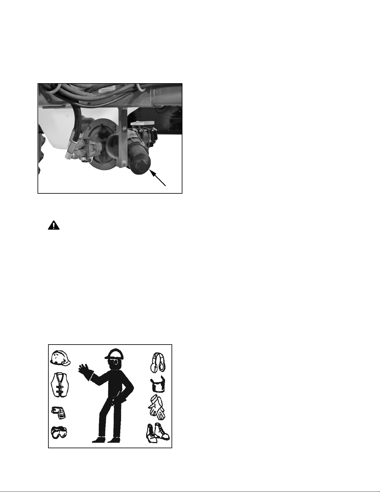
20. System Screen: The liquid system is equipped with a screen in
suction line to remove dirt and impurities. Close
valve, remove screen and wash with clear water
on a daily basis. Clean liquid is required to prevent
nozzle plugging.
21. Sump:
Remove plug on end of screen canister to drain
tank at the end of each season.
22. Add only the amount of liquid to the tank that is
required for the job. Excess liquid must be
removed from the machine at the end of the season to prevent corrosion of metal parts.
Emptying at the end of each day is also
recommended to prevent corroding over night.
Remove all excess liquid from the machine
through the plug on the bottom of the screen
canister.
Note: Always turn sump valve off
whenever working on liquid circuit
components to isolate the liquid in tank.
23. Drive at a comfortable speed whenever operating
in field. Operating too fast for conditions can
cause coulter depth to vary and lead to inconsistent application efficiencies.
WARNING
Prevent serious injury or death.
Check chemical or fertilizer MSDS for
proper handling instructions.
Toxic chemicals can enter the body by
breathing, spray or contact with bare skin.
Do not take a chance with your health and
safety.
24. To fold toolbar for transporting:
•Engage tractor remote #1 to fully raise center
section.
•Remove lock out pins.
•Engage tractor remote #3 to fold outer flip wings
to transport position.
•Engage remote #2 to fold main wings to transport
position. With the toolbar fully raised, place transport brace or cylinder stops on main lift cylinder
rams.
•Install transport pins at main wing hinge area.
8300 Liquid Fertilizer Applicator 28 FAST AG Solutions
Page 30
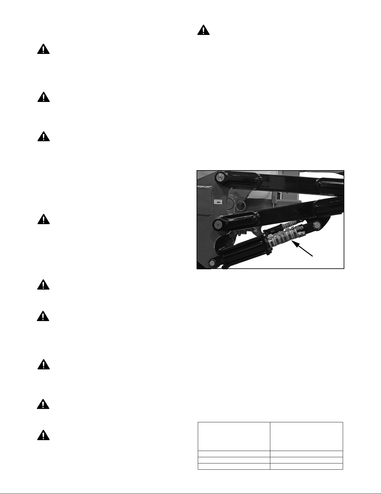
3.10 Transport
Read and understand ALL information in
Operator’s Manual regarding procedures and
SAFETY when operating applicator in the field
and/or on the road.
Check with local authorities regarding
applicator transport on public roads. Obey all
applicable laws and regulations.
Always travel at a safe speed. Use caution
when making corners or meeting traffic.
NOTICE
Prevent equipment damage.
Verify main tank is empty before
transporting on road.
Stay away from overhead power lines during
transport. Electrocution can occur without direct
contact.
1. Be sure all bystanders are clear of machine.
2. Be sure that applicator is properly connected towing vehicle. Always attach safety chain between
machine and tractor and install a retainer through
drawbar pin.
3. Stay away from overhead power lines when folding or extending the wings. Electrocution can
occur without direct contact.
4. Install transport lock spacers on lift cylinders before transporting.
Make sure SMV (Slow Moving Vehicle)
emblem and all lights and reflectors that are
required by the local highway and transport
authorities are in place, are clean and can be
seen clearly by all overtaking and oncoming
traffic.
Daybreak and dusk are particularly dangerous
and pilot vehicles are recommended.
Be sure applicator is hitched securely to towing
vehicle and a retainer is used through drawbar
pin. Always attach a safety chain between
frame and towing vehicle.
Keep to right and yield right-of-way to allow
faster traffic to pass. Drive on the road
shoulder, if permitted by law.
Note: Add more lock spacers to prevent
the tool bar from dropping during
transport.
5. Depending on machine configuration, wheels may need to be moved in, inverted or duals removed to reduce machine transport width to 18 feet or less.
6. Make sure SMV (Slow Moving Vehicle) emblem and all lights and reflectors that are required by local highway and transport authorities are in place, are clean and can be seen clearly by all overtaking and oncoming traffic.
Do not exceed 20 mph (32 km/h). Reduce
speed on rough roads and surfaces.
Always use hazard warning flashers on tractor
and applicator when transporting unless
prohibited by law.
8300 Liquid Fertilizer Applicator 29 FAST AG Solutions
7. It is not recommended that machine be transported faster than 20 mph (32 km/ hr).
Road Speed Weight of fully equipped
or loaded machine relative
to weight of towing
machine
Up to 32 km/h (20 mph) 1 to 1, or less
Up to 16 km/h (10 mph) 2 to 1, or less
Do not tow More than 2 to 1
Page 31

8. Do not allow riders on machine or tractor.
9. During periods of limited visibility, use pilot vehicles and use extra lights on machine.
9. Fold flip wings and outer wings to transport configuration.
10. Install transport brace or cylinder stops on main lift cylinders. Lower machine onto cylinder stops.
10. Always use hazard flashers on tractor and applicator when transporting unless prohibited by law.
3.11 Storage
Store unit in an area away from human activity.
Do not permit children to play on or around
stored applicator.
3.11.1 Placing In Storage
At end of season, thoroughly inspect and prepare
applicator for storage. Repair or replace any worn or
damaged components to prevent any unnecessary
down time at beginning of next season.
1. Empty remaining liquid from tank.
2. Open liquid line connections, screen canister and pump. Drain all fluids out of system. Reinstall all plugs.
3. Use 10 gallons Marine RV Anti freeze, pump through screens, valve, nozzles/check valves and orifices/tips.
4. Thoroughly wash machine using a pressure washer to remove all dirt, mud, debris or residue to protect against corrosion.
5. Lubricate all grease points. Make sure all grease cavities have been filled with grease to remove any water residue from washing.
11. Move machine to a storage position.
12. Select an area that is dry, level and free of debris.
13. Place planks under jack for added support if required.
14. Place tractor remote levers in float to relieve hydraulic pressure and unhook applicator from tractor.
3.11.2 Removing From Storage
1. Clear area of bystanders, especially small children, and remove foreign objects from machine
and working area.
2. Attach tractor to applicator.
3. Check
A. Attach and secure all liquid lines.
B. Coulters and nozzles.
C. All hardware. Tighten as required.
D. Tire pressure.
E. All hydraulic lines, fittings and connections.
Tighten as required.
4. Lubricate all grease fittings.
5. Replace any defective parts.
6. Turn pump metering system momentarily.
7. Make sure it turns freely.
8. Add a small amount of liquid to tank. Turn metering pump on momentarily and check that liquid
comes out of each nozzle.
9. Follow pre-operation checklist (Section 3.4) before using.
6. Inspect all hydraulic hoses, couplers and fittings. Tighten any loose fittings. Replace any hose that is damaged or separating from crimped end of a fitting.
7. Inspect all liquid lines and connections. Tighten any loose fittings. Replace any line that is cut, nicked or abraded.
8. Touch up all paint nicks and scratches to prevent rusting.
8300 Liquid Fertilizer Applicator 30 FAST AG Solutions
Page 32
4. Service And Maintenance
4.1 Service
Review the Operator’s Manual and all safety
items before working with, maintaining or
operating the applicator.
Lower machine to the ground, place all controls
in neutral, stop engine, set park brake, remove
ignition key, and wait for all moving parts to
stop before servicing, adjusting, repairing or
unplugging.
Follow good shop practices:
•Keep service area clean and dry.
•Be sure electrical outlets and tools are properly grounded.
•Use adequate light for the job at hand.
Before applying pressure to a hydraulic system,
make sure all components are tight, hoses and
couplings are in good condition.
Relieve pressure from hydraulic circuit before
servicing or disconnecting from tractor.
4.1.1 Fluids And Lubricants
Grease:
Use an SAE multi-purpose high temperature
grease with extreme pressure (EP) performance.
Also acceptable is an SAE multi-purpose lithium
base grease.
Storing Lubricants:
Your machine can operate at top efficiency only if
clean lubricants are used. Use clean containers to
handle all lubricants. Store them in an area
protected from dust, dirt, moisture and other
contaminants.
4.1.2 Greasing
Refer to Section 4.1.1 for recommended grease. Use
Maintenance Checklist provided to keep a record of all
scheduled maintenance.
1. Use only a hand-held grease gun for all greasing.
Keep hands, feet, clothing and hair away from
all moving and/or rotating parts.
Clear the area of bystanders, especially
children, when carrying out any maintenance
and repairs or making any adjustments or
filling.
Place stands or blocks under the frame before
working beneath the machine or when
changing tires.
Be sure all guards are in place and secured
when maintenance work is completed.
Use only tools, jacks and hoists of sufficient
capacity for the job.
2. Wipe grease fitting with a clean cloth before greasing, to avoid injecting dirt and grit.
3. Replace and repair broken fittings immediately.
4. If a fitting will not take grease, remove and clean thoroughly. Also clean and lubricant passageway. Replace fitting if necessary.
8300 Liquid Fertilizer Applicator 31 FAST AG Solutions
Page 33
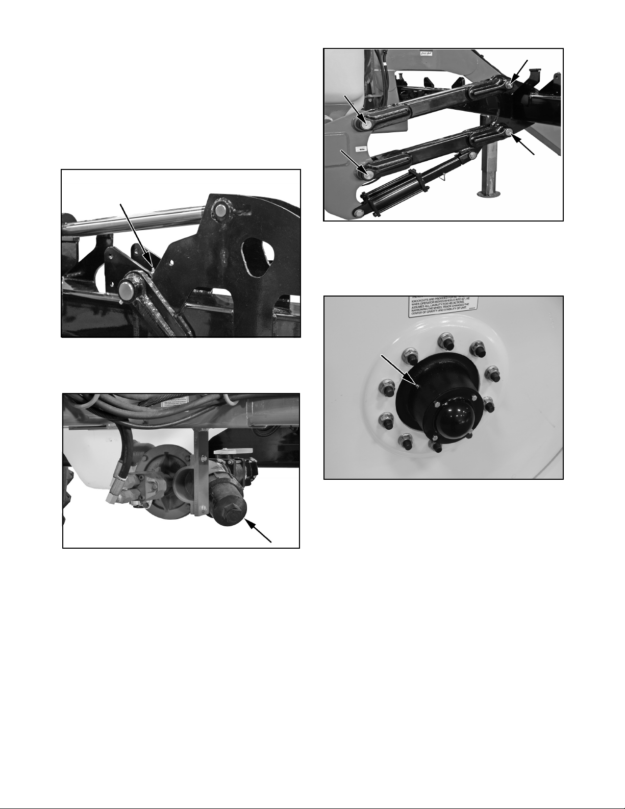
4.1.3 Servicing Intervals
8 Hours or Daily
1. Grease flip wing tool bar hinges (6 locations each hinge).
2. Grease inner wing hinges and fold pins (2 locations on each hinge).
Annually
1. Grease wheel bearings. One per side.
3. Remove and wash fertilizer strainer screen using clean water.
4. Grease tool bar parallel linkage (4 locations per side - 8 total).
2. Clean and wash machine.
8300 Liquid Fertilizer Applicator 32 FAST AG Solutions
Page 34

4.1.4 Service Record
See Lubrication and Maintenance sections for details of service.
Copy this page to continue record.
Daily
Item Hours
Serviced
By
Flip Wing Hinges (L)
Inner Wing Hinges (L)
Strainer Screen (C)
Tool Bar Parallel Linkage
(L)
Action Code: C = Clean L = Lubricate
Daily
Item Hours
Serviced
By
Flip Wing Hinges (L)
Inner Wing Hinges (L)
Strainer Screen (C)
Tool Bar Parallel Linkage
(L)
Action Code: C = Clean L = Lubricate
Annually
Item Hours
Serviced
By
Wheel Bearings (L)
Wash Machine (C)
Action Code: C = Clean L = Lubricate
8300 Liquid Fertilizer Applicator 33 FAST AG Solutions
Page 35
4.2 Maintenance
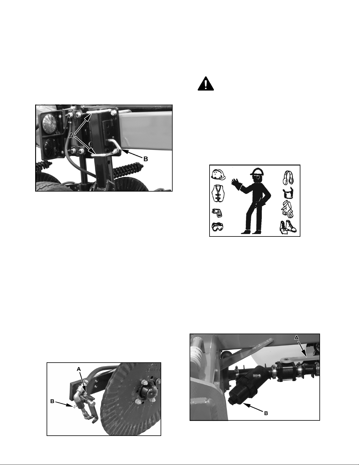
4.2.1 Adjust Gauge Wheel Height
4.2.3 Filter
1. Clean the filter at the start of each day when tank is empty or dirt is detected in system.
1. Loosen U-bolts (A).
2. Remove pin (B) and adjust gauge wheel height as desired.
3. Install pin, lock pin and tighten U-bolts (A).
4.2.2 Nozzles
1. Clear area of bystanders.
2. Clear area of bystanders.
WARNING
Prevent serious injury or death.
Check chemical or fertilizer MSDS for
proper handling instructions.
Toxic chemicals can enter the body by
breathing, spray or contact with bare skin.
Do not take a chance with your health and
safety.
2. Extend wings and raise tool bar to its fully up position.
3. Place safety stands under center tool bar or install transport lock spacers over lift cylinder rams.
4. Nozzle Angle:
•The best results are obtained when nozzle directs
liquid approximately 1 inch (25 mm) behind
coulter.
•Loosen setscrew (A) to set nozzle at required
angle and centered behind coulter.
5. Nozzle Spray Pattern
•Sight along nozzle and coulter. Nozzle should
direct liquid directly behind coulter.
•Loosen setscrew (B) to adjust nozzle spray parallel with furrow.
3. Close sump valve (A) if there is liquid in tank.
4. Relieve pressure in liquid circuit.
5. Remove cap (B) to access screen.
6. Use clear water to clean screen.
7. Install screen in canister and tighten by hand. Do not over tighten canister and crack head.
8. Open sump valve (A) if there is liquid in tank.
8300 Liquid Fertilizer Applicator 34 FAST AG Solutions
Page 36
5. Troubleshooting
In the following table, two problems, causes and solutions to problems are listed that you may encounter.
If you encounter a problem that is difficult to solve, even after having read through this troubleshooting section,
please call your local FAST AG Solutions dealer or the factory.
Before you call, please have this Operator’s Manual and the serial number from your machine ready.
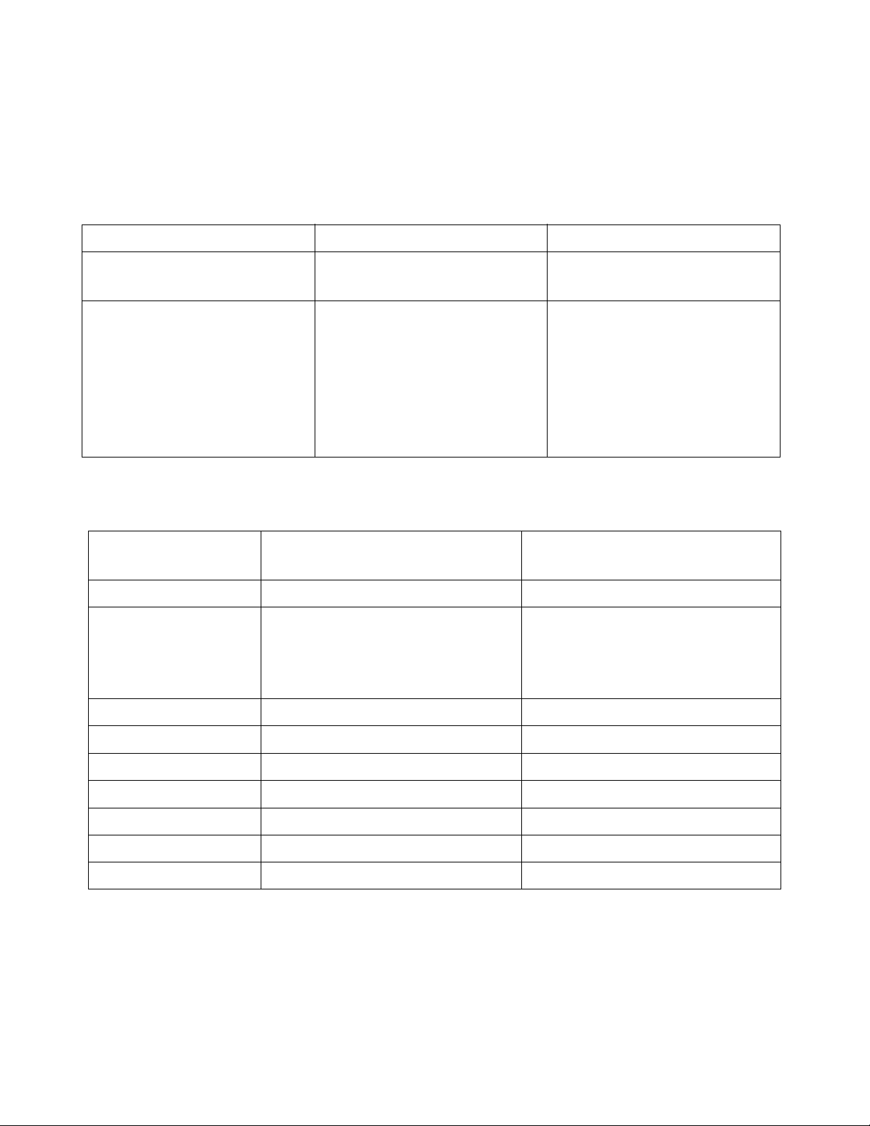
PROBLEM CAUSE SOLUTION
Running out of liquid. Application rate too high Reset application rate. Refer to
manual for pump.
Liquid remaining. Application rate too low.
Intermittent speed signal.
6. Specifications
6.1 Mechanical
Dimensions 8310 / 8313
30 ft 11 Coulters
Length 16' 7'' 20' 4''
Width
Field
Transport
Transport Height 13' 4'' 13' 4''
25' 5''
16' 10''
8318 / 8324
40 ft 15 Coulters
35' 5''
16' 10''
Check line strainers for blockage.
Reset application rate. Refer to
manual for pump.
Check and set speed sensor on
hub.
Tank Capacity In Gallons 1050 or 1350 1800 or 2400
Main Tires See Tire Chart See Tire Chart
Lug Nut Torque 265 lb/ft 265 lb/ft
Gauge Wheel 20.5 x 8-10 20.5 x 8-10
Tire Pressure 90 90
Lug Nut Torque 70 lb/ft 70 lb/ft
Specifications subject to change without notice.
8300 Liquid Fertilizer Applicator 35 FAST AG Solutions
Page 37
Checking Tire Pressure
CAUTION: Avoid loss of vehicle control during transport from failure of overloaded tires, which could cause serious injury or death to you or others.
Equal pressure in all tires is necessary for even penetration. A low tire will cause deeper penetration on one side than other. Increased penetration on one side will result in side draft of
machine. Inflate tires to shown specification.
Tire Size Pressure
380/90R46 LR168 (Singles) 538 kPa (8.38 bar) (78 psi)
380/90R46 LR149 (Duals) 255 kPa (2.55 bar) (37 psi) Inner
227 kPa (2.28 bar) (33 psi) Outer
380/90R54 LR170 (Singles) 517 kPa (5.17 bar) (75 psi)
380/90R54 LR152 (Duals) 255 kPa (2.55 bar) (37 psi) Inner
227 kPa (2.28 bar) (33 psi) Outer
480/80R50 LR176 545 kPa (5.00 bar) (73 psi)
20.5 x 8-10 621 kPa (6.21 bar) (90 psi)
6.7R15 303 kPa (3.03 bar) (44 psi)
NOTE: Tire pressure is directly linked to LRXXX (bold italic). Make sure of the load rating
of the tire before adding any air to the tire.
8300 Liquid Fertilizer Applicator 36 FAST AG Solutions
Page 38
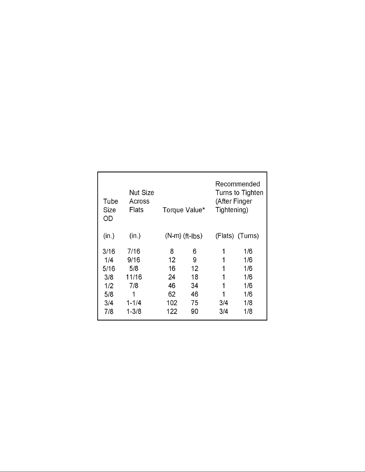
6.2 Hydraulic Fitting Torque
Tightening flare type tube fittings*
1. Check flare and flare seat for defects that might cause leakage.
2. Align tube with fitting before tightening.
3. Lubricate connection and hand tighten swivel nut until snug.
4. To prevent twisting tubes or hoses, use two wrenches. Place one wrench on connector body and with second wrench tighten swivel nut to torque shown.
*Torque values shown are based on lubricated connections.
8300 Liquid Fertilizer Applicator 37 FAST AG Solutions
Page 39
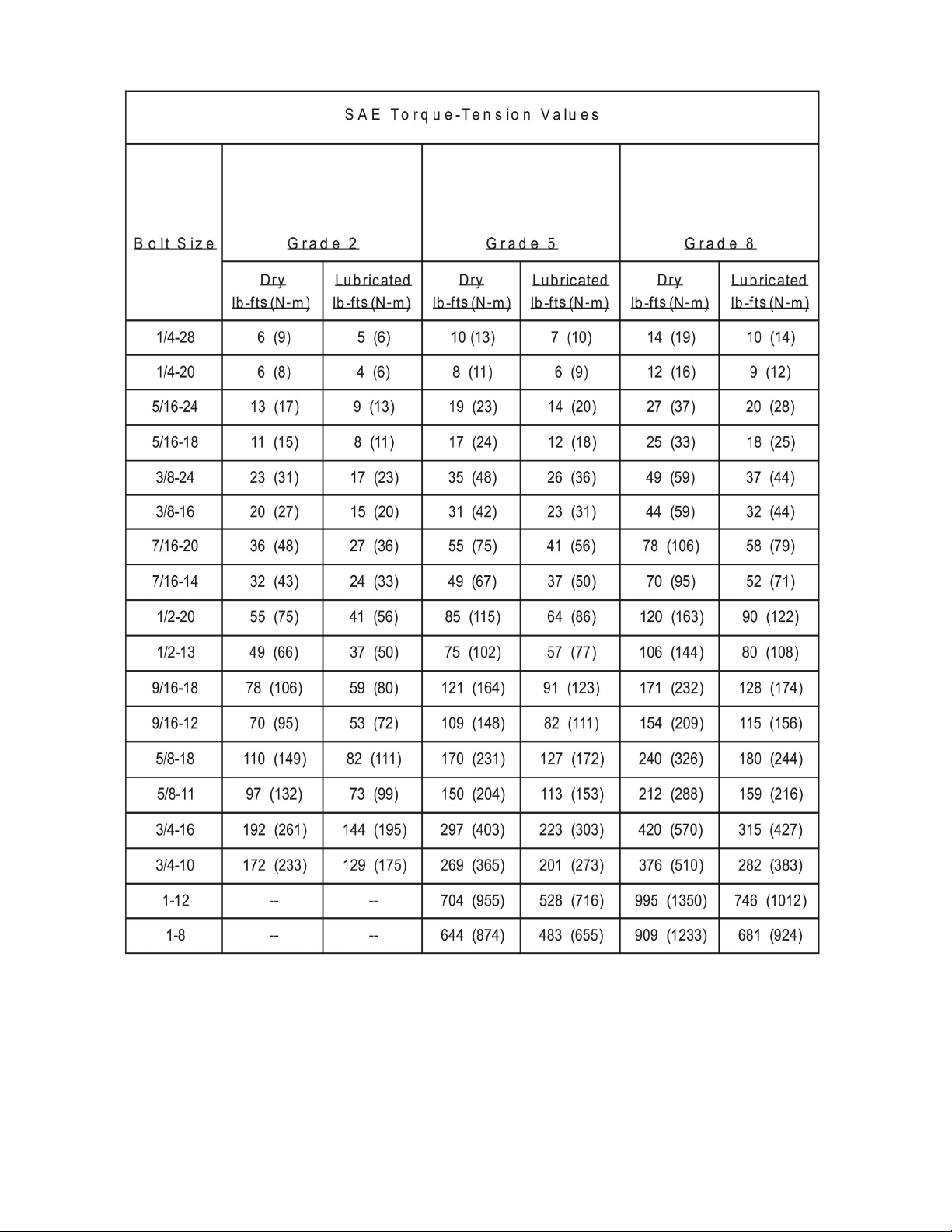
8300 Liquid Fertilizer Applicator 38 FAST AG Solutions
Page 40
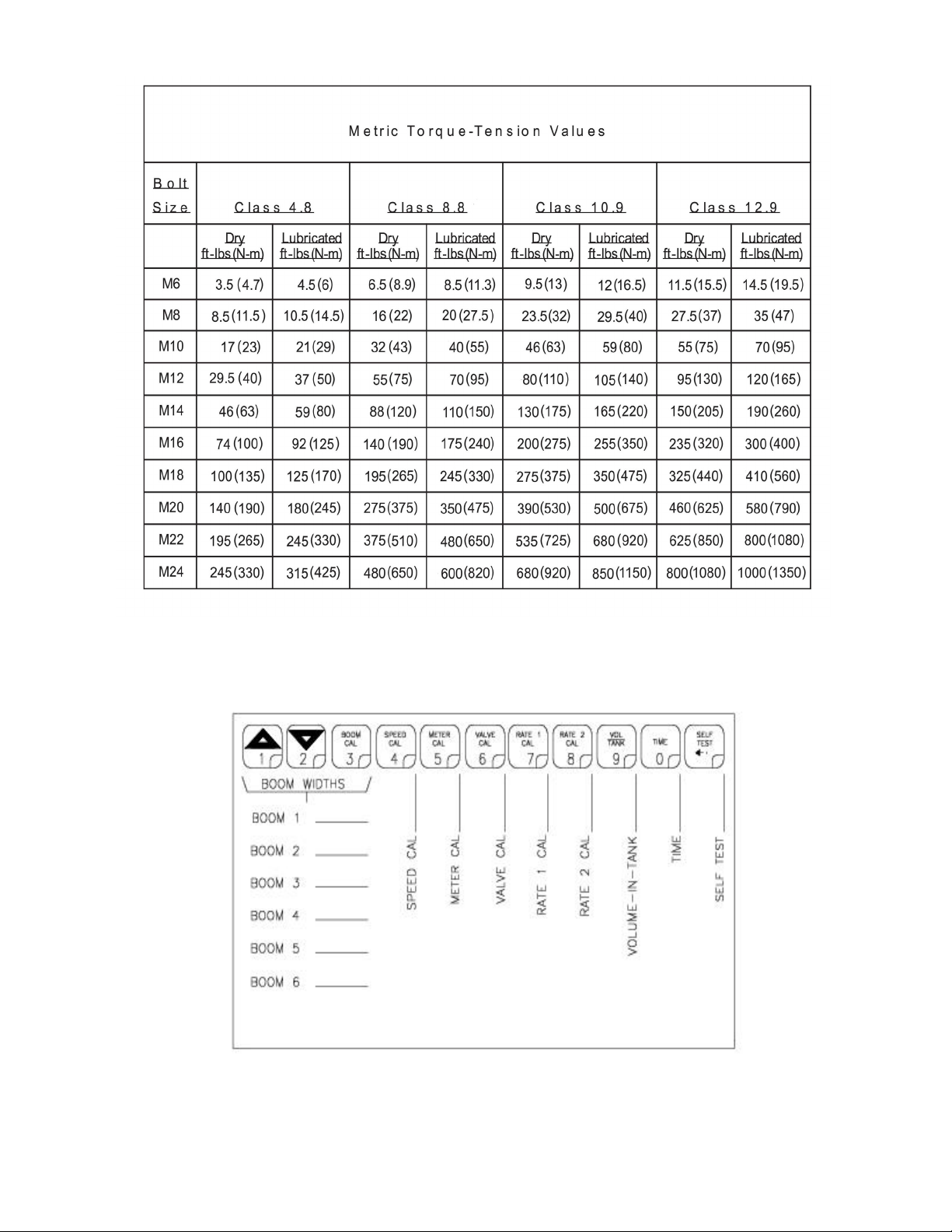
8300 Liquid Fertilizer Applicator 39 FAST AG Solutions
Page 41

NOTES
8300 Liquid Fertilizer Applicator 40 FAST AG Solutions
Page 42

FAST GLOBAL SOLUTIONS
4130 Commerce Boulevard
Windom, MN 56101
1-800-772-9279 Toll Free
1-507-427-3861 Voice
1-507-427-3030 Fax
www.fastsprayers.com
8300 Liquid Fertilizer Applicator 41 FAST AG Solutions
 Loading...