

Page 1
1
Standalone XIM™
Thank you for choosing FAST™ products; we are proud to be your manufacturer of choice. Please read this
instruction sheet carefully before beginning installation, and also take a moment to review the included limited
warranty information.
These instructions focus on the Standalone XIM™. Please refer to the original XIM™ instructions (Part
#FAST4-101) for general XIM™ information.
Standalone Modes
The XIM™ has three modes of Standalone operation.
1. Onboard – adjustments made with physical switches mounted directly on the XIM™ circuit board.
2. Remote – adjustments made through a small, handheld device intended to be used in the cockpit.
3. PC Software – adjustments made through a software package loaded on a laptop.
Onboard Switch Settings
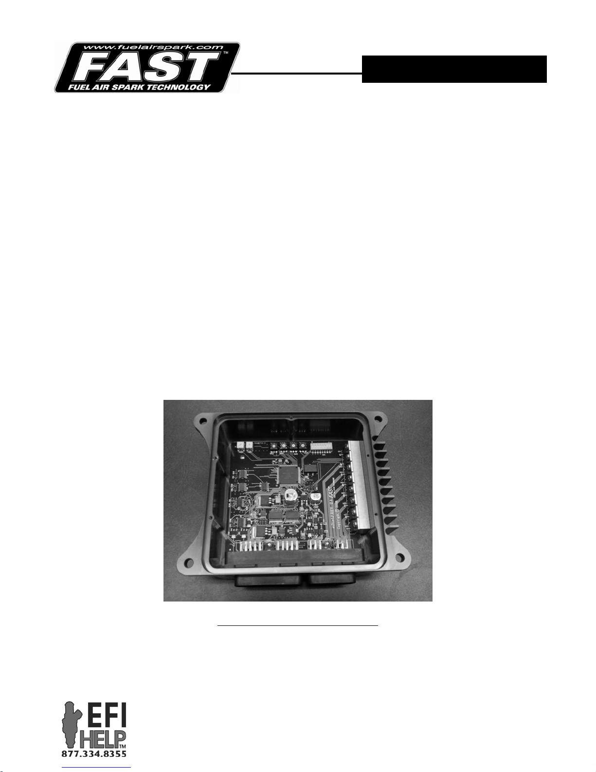
The XIM™ is configured through a series of DIP switch settings. The switches are located under the back cover
of XIM™. To access the switches, simply take the lid off by removing the 5 screws, being careful not to tear the
gasket beneath the lid.
INSTRUCTIONS
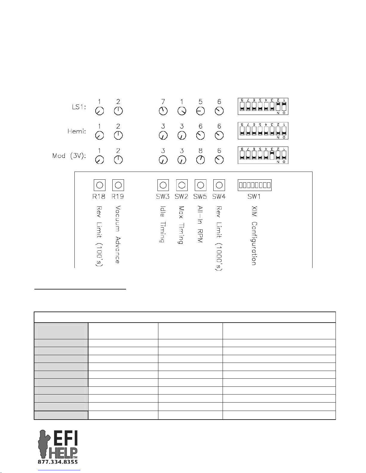
These example settings can be used to get up and running quickly. They are on the “safe” side. If desired, any of
the settings can be adjusted to suit the motor or application. More detail about each switch setting is given on the
following page.
Quick Start Guide for Onboard Mode
FAST™
FAST™
3400 Democrat Rd.
3400 Democrat Rd.
Memphis, TN 38118
Memphis, TN 38118
Phone: (901) 260-3278 Fax: (901) 366-1807
Phone: (901) 260-3278 Fax: (901) 375-3408
www.fuelairspark.com
www.fuelairspark.com
Part # FAST4-160
Revised 11/30/09
Part #???
Revised ??????
Page 2
2
For reference, these LS1 settings will give you…
Idle timing: 20° (idle timing plus vacuum advance gives 30° at idle)
Max timing: 24°
All-in RPM: 2800 rpm
Vacuum Advance: 10° (added to base timing at low load)
Rev Limit: 6000 rpm
SW1 (long, 8 DIP switch toggles)
All modes of XIM™ operation require that these be set per application as shown below. Note that #7 needs to be
“ON” to operate in any Standalone mode.
DIP Switch (1-4)
[0=OFF, 1=ON] Ignition Strategy Crank Input
0 - 0 - 0 - 0 Crank Trigger 1/2/3/4X, 50* BTDC 50
1 - 0 - 0 - 0 OE Crank Trigger 1/2/3/4X, 1-10* BTDC Actual Crank Position (1-10) + 45
1 - 0 - 1 - 1 Ford Mod, 2 or 4 Valve 36-1 (1 tooth cam) 60
1 - 1 - 0 - 1 Ford Mod, 3 Valve 36-1 (5 tooth cam) 60
1 - 1 - 1 - 1 Chrysler Hemi 36-2-2 50
1 - 1 - 1 - 0 Chrysler Hemi Eagle 60-2 54
0 - 0 - 1 - 1 GM Gen 3 - LS1/LS6 24X (Special) 50
0 - 1 - 1 - 1 GM Gen 4 – LS2/LS7 60-2 (4 pulse cam) 49
0 - 1 - 0 - 1 GM Gen 4 / Gen 3 Cam 60-2 (1 pulse cam) 49
1 - 0 - 0 - 1 24 Pulse Dist. Plug 24X (Even, 1 cam) 50 - 60
XIM™ DIP Switches
“Crank Ref. Angle (*BTDC)” setting
FAST™
FAST™
3400 Democrat Rd.
3400 Democrat Rd.
Memphis, TN 38118
Memphis, TN 38118
Phone: (901) 260-3278 Fax: (901) 366-1807
Phone: (901) 260-3278 Fax: (901) 375-3408
www.fuelairspark.com
www.fuelairspark.com
in C-Com XFI™ software
Part # FAST4-160
Revised 11/30/09
Part #???
Revised ??????
Page 3
3
DIP Switch (5-6)
[0=OFF, 1=ON]
0 - 0 2 Cylinder 1 Standalone 1 Coil per Cylinder
1 - 0 4 Cylinder 0 CAN Enabled 0 Waste Spark
0 - 1 6 Cylinder
1 - 1 8 Cylinder
# of
Cylinders
SW2 / SW3 / SW4 / SW5 (rotaries with detents)
SW2, SW3 and SW5 settings are only required for Onboard mode. They are not used with the optional Remote
or PC software.
SW3
SW2
SW5
SW4*
Idle timing (°BTDC) 2 6 24
Max timing (°BTDC) 2 22 40
All in (RPM) 200 1800 3600
Rev Limit 1000's
* SW4 is also used to select between the three modes of Standalone operation. It is set to 0 for PC Software
mode, 1 for Remote mode, or 3-9 for Onboard mode.
SW3 SW2 SW5 SW4*
Switch
Position
0
1
2
3
4
5
6
7
8
9
Idle Timing
(°BTDC)
6 22 1800 PC Software n/a
8 24 2000 Remote n/a
10 26 2200 n/a n/a
12 28 2400 Onboard 3000
14 30 2600 Onboard 4000
16 32 2800 Onboard 5000
18 34 3000 Onboard 6000
20 36 3200 Onboard 7000
22 38 3400 Onboard 8000
24 40 3600 Onboard 9000
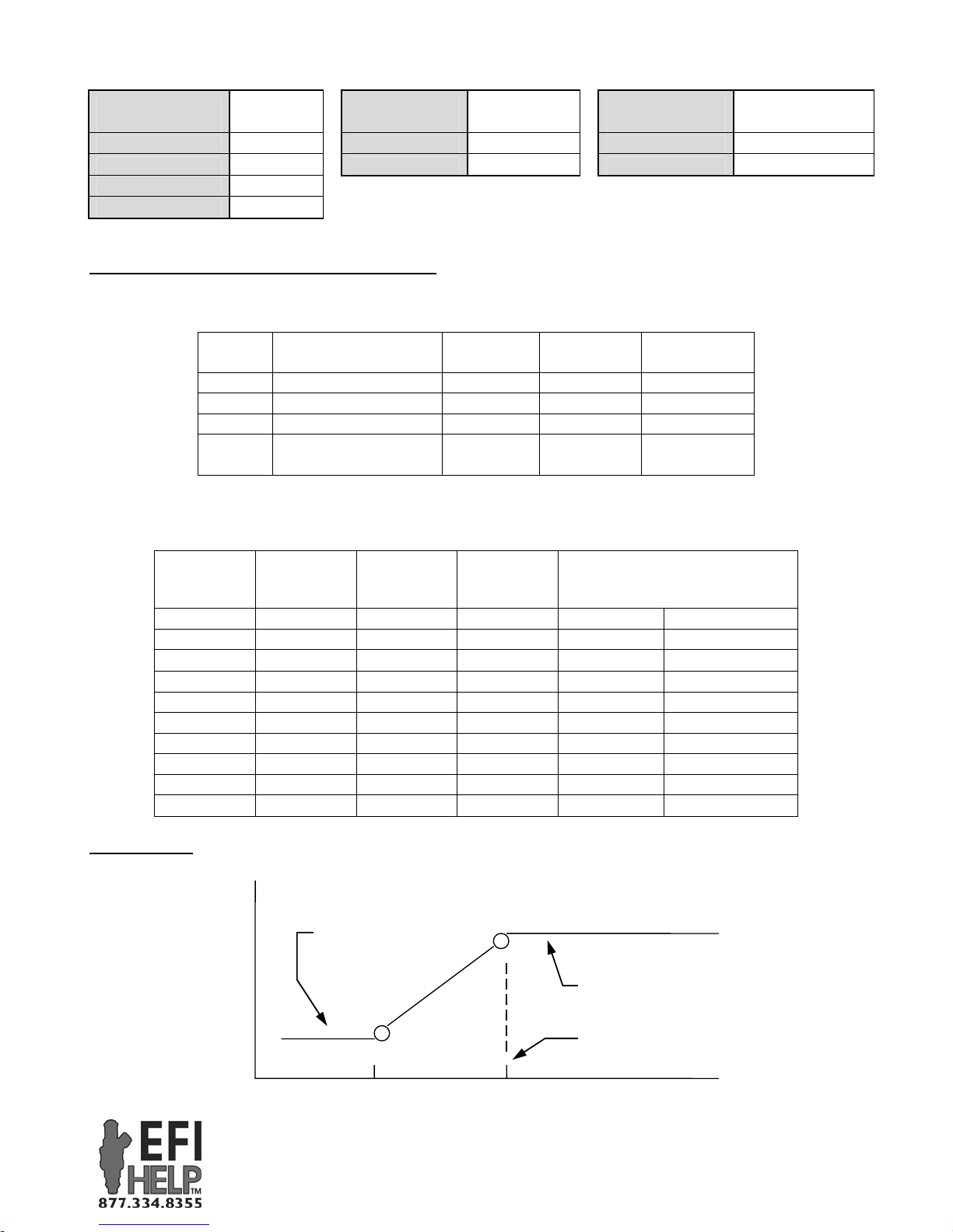
Timing Curve
SW2, SW3 & SW5 are used to construct a base timing curve.
Ignition Timing
DIP Switch (7)
[0=OFF, 1=ON]
“CAN Enabled” allows XIM™ to
communicate with XFI™
Setting Resolution
(RPM) 1000
Max timing
(°BTDC)
Operation
Mode
Min
(position 0)
(position 3)
3000 9000
All in
(RPM)
Standalone
Mode
SW3: Idle Timing
SW2: Max Timing
SW5: All-in RPM
1250
.
RPM
FAST™
FAST™
3400 Democrat Rd.
3400 Democrat Rd.
Memphis, TN 38118
Memphis, TN 38118
Phone: (901) 260-3278 Fax: (901) 366-1807
Phone: (901) 260-3278 Fax: (901) 375-3408
www.fuelairspark.com
www.fuelairspark.com
DIP Switch (8)
[0=OFF, 1=ON] Coil Layout
“Waste Spark” – Each coil fires two
companion cylinders simultaneously.
Max
(position 9)
Rev Limit
1000’s (RPM)
Part # FAST4-160
Revised 11/30/09
Part #???
Revised ??????
Page 4
4
R18 / R19 (rotaries without detents)
R18 and R19 settings are only required for Onboard mode. They are not used with the optional Remote or PC
software. These can be set fully counter-clockwise (minimum setting), fully clockwise (maximum setting), or
any position in between.
R18
R19
Min
(full ccw)
Setting Resolution
Rev Limit 100’s
(RPM) n/a 0 900
Vacuum advance
(°) n/a 0 20
(position 1)
Max
(full cw)
(position 3)
Rev Limiter
SW4 and R18 are both used to set the rev limiter in Onboard mode. Adding the two settings together gives the
rev limit. For example…
SW4 : position 6 = 6,000 RPM
R18 : center of rotation = 450 RPM.
Together, they set the rev limit to 6,450 RPM.
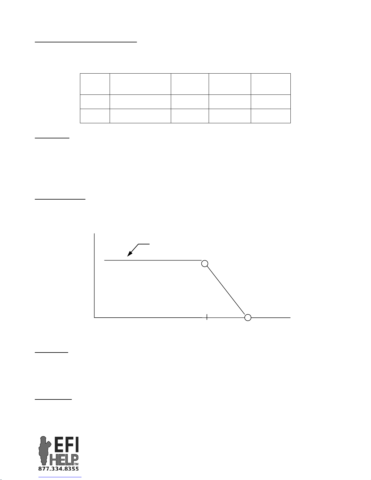
Vacuum Advance
The vacuum advance feature adds an adjustable amount of timing on top of the base timing curve. The full
amount is added at lower load and phased out as load increases. The MAP sensor must be installed (harness
plugged into sensor and a vacuum line run from the sensor to the intake manifold) for this feature to work
properly. In Onboard mode, R19 can be turned fully counter-clockwise to disable the vacuum advance feature.
R19: Vacuum Advance
Added Timing
Status LED
The Status LED on the XIM™ will…
• Flash briefly once a second to confirm XIM™ is set for Standalone operation
• Flash an even on/off pattern when started up in flash mode (blue “Flash” wire grounded at key-on.
Used to update firmware in XIM™.)
Tach Output
Pin 30-A3 is a 12V square wave tach output. It is available as a loose Brown/white wire and at pin F of the
“CAM/HALL EFFECT” connector.
Manifold Pressure
73 kPa
87 kPa
FAST™
FAST™
3400 Democrat Rd.
3400 Democrat Rd.
Memphis, TN 38118
Memphis, TN 38118
Phone: (901) 260-3278 Fax: (901) 366-1807
Phone: (901) 260-3278 Fax: (901) 375-3408
www.fuelairspark.com
www.fuelairspark.com
Part # FAST4-160
Revised 11/30/09
Part #???
Revised ??????
Page 5
5
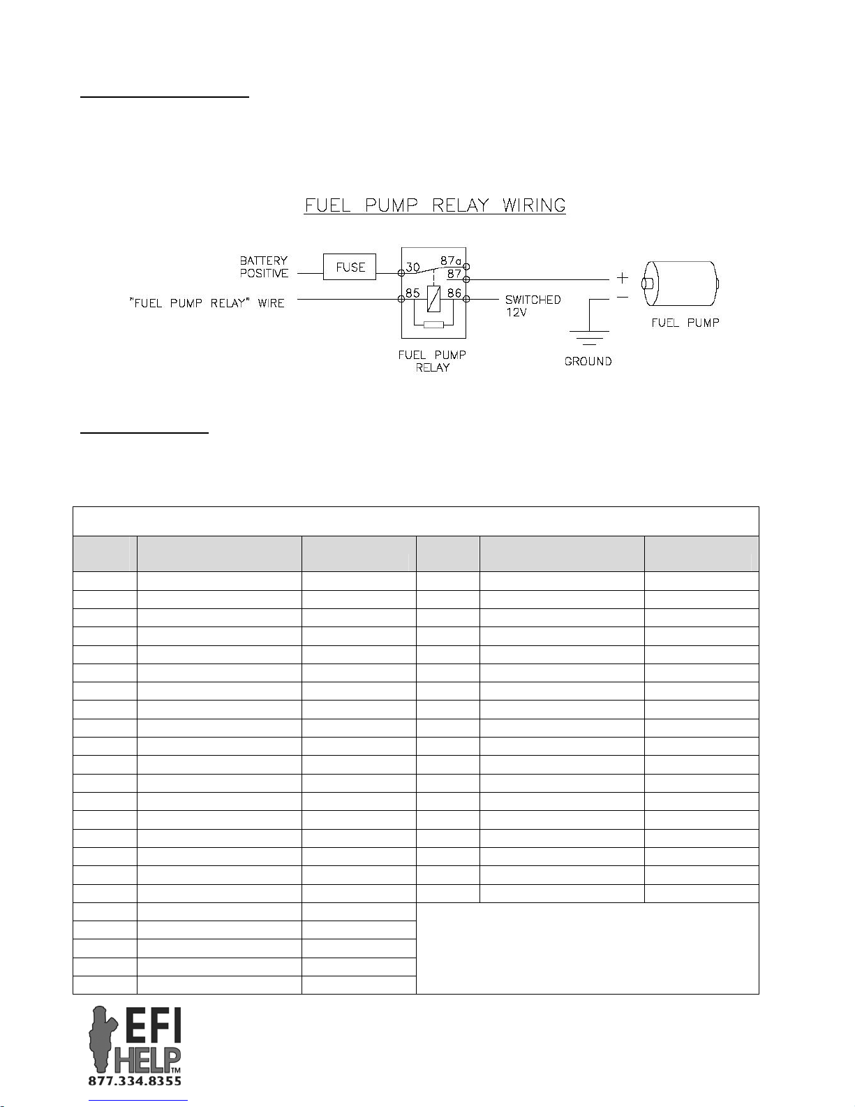
Fuel Pump Relay Control
Pin 18-B3 is a fuel pump relay output. It is available as a loose Green wire. It can be wired to the negative side
of a fuel pump relay to control an electric fuel pump. (Do NOT connect it directly to a fuel pump.) The pump
will be primed at key-on. And then will run whenever the XIM™ sees an RPM signal.
Unused Connectors
When using the XIM™ in one of the Standalone modes, the “CAN LINK” and “TO XFI CAM/HALL
EFFECT” connections are not used.
XIM™ Pinout Chart
XIM™
Pin Function Wire Color
30-A1
30-A2
30-A3
30-B1
30-B2
30-B3
30-C1
30-C2
30-C3
30-D1
30-D2
30-D3
30-E1
30-E2
30-E3
30-F1
30-F2
30-F3
30-G1
30-G2
30-G3
30-H1
30-H2
Inductive Crank Input Red
Discrete Crank Input Yellow
Crank Output / Tach Brown/White
Digital GND Black (/White)
Digital GND Black/White
Cam Output Yellow/Black
Inductive Cam Input Red
Discrete Cam Input Brown
Flash Enable Input Blue
Digital GND Black (/White)
Digital GND Black/White
Load Input White/Violet
Analog 2 Input*
5V Reference Red/White
Analog GND Black/Pink
RS-232 RxD Black
RS-232 TxD Red
Dig GND (RS-232) White
CAN_H Yellow
CAN_L Green
Digital GND Black/White
EST Output A Purple
EST Output B Purple/White
XIM™
Pin Function Wire Color
18-A1
18-A2
18-A3
18-B1
18-B2
18-B3
18-C1
18-C2
18-C3
18-D1
18-D2
18-D3
18-E1
18-E2
18-E3
18-F1
18-F2
18-F3
+12V Switched Input Pink
Retard #2 Input Purple
Digital GND Black/White
Battery Input Red
Retard #1 Input Gray
Fuel Pump Output Lt. Green
Coil Output A Orange
Auxiliary Output*
Power GND Black
Coil Output D Purple
Coil Output C Gray
Coil Output B Blue
Coil Output E Black
Power GND Black
Power GND Black
Coil Output F Brown
Coil Output G Yellow
Coil Output H Green
* Reserved for future use
Notes:
See letters and numbers molded into sides of
FAST™
FAST™
3400 Democrat Rd.
3400 Democrat Rd.
Memphis, TN 38118
Memphis, TN 38118
Phone: (901) 260-3278 Fax: (901) 366-1807
Phone: (901) 260-3278 Fax: (901) 375-3408
www.fuelairspark.com
www.fuelairspark.com
Part # FAST4-160
Revised 11/30/09
Part #???
Revised ??????
Page 6

6
30-H3
30-J1
30-J2
30-J3
30-K1
30-K2
30-K3
2-Step Input Orange
EST Output C Red
EST Output E Blue/White
EST Output G Green/White
EST Output D Red/White
EST Output F Green
EST Output H Blue
FAST, Inc. warrants that all of its products are free from defects in material and workmanship for a period of 1
year from the date of purchase. This limited warranty shall cover the original purchaser.
FAST, Inc.’s obligation under this warranty is limited to the repair or replacement of its product. To make a
warranty claim, the part must be returned within 1 year of purchase to the address listed below, freight prepaid.
Items covered under warranty will be returned to you freight collect. It is the responsibility of the installer to
ensure that all of the components are correct before installation. We assume no liability for any errors made in
tolerances, component selection, or installation.
There is absolutely no warranty on the following:
•Any parts used in racing applications.
•Any product that has been physically altered, improperly installed or maintained.
•Any product used in improper applications, abused, or not used in conjunction with the proper parts.
•Damage due to excessive manifold pressure, i.e. nitrous backfires, engine misfire, etc.
There are no implied warranties of merchantability or fitness for a particular purpose. There are no
warranties, which extend beyond the description of the face hereof. FAST, Inc. will not be responsible for
incidental and consequential damages, property damage or personal injury damages to the extent permitted by
law. Where required by law, implied warranties or merchantability and fitness are limited to a term of 1 year
from the date of original purchase.
This warranty gives you specific legal rights and you may also have other legal rights, which vary from state to
state.
connectors to find pin locations.
“30-“ and “18-“ refer to 30 way and 18 way
connector.
Limited Warranty
FAST™
FAST™
3400 Democrat Rd.
3400 Democrat Rd.
Memphis, TN 38118
Memphis, TN 38118
Phone: (901) 260-3278 Fax: (901) 366-1807
Phone: (901) 260-3278 Fax: (901) 375-3408
www.fuelairspark.com
www.fuelairspark.com
Part # FAST4-160
Revised 11/30/09
Part #???
Revised ??????
 Loading...