

Page 1
DTC500 Series Card Printer/Encoders
User Guide (Rev. 6.0)
DTC500-LE (Single-Sided Card Printer/Encoders) (See DTC510 information)
DTC510 (Single-Sided Card Printer/Encoders)
DTC515 (Single-Sided Card Printer/Encoders)
DTC515-LC (Single-Sided Card Printer/Encoders)
DTC520 (Dual-Sided Card Printer/Encoders)
DTC525 (Dual-Sided Card Printer/Encoders)
DTC525-LC (Dual-Sided Card Printer/Encoders)
Part Number: L000699
Page 2

RESTRICTED USE ONLY FARGO Electronic, Inc.
DTC500 Series Card Printer/Encoders User Guide (Rev. 6.0), property of FARGO
Electronics, Incorporated
Copyright 2002 by FARGO Electronics, Incorporated. All rights reserved. Printed in the
United States of America. Exclusive permission is granted to authorized resellers of FARGO
products to reproduce and distribute this copyrighted document to authorized FARGO
customers, who have signed a “no disclosure agreement” regarding the restricted,
proprietary use of said document.
The revision number for this document will be updated to reflect changes, corrections,
updates and enhancements to this document.
Revision Control
Date Document Title
Number
Revision 6.0 1 March 2006 DTC500 Card Printer/Encoders User Guide
Revision 5.0 1 January 2004 Same document title
Revision 4.0 15 September 2003 Same document title
These reference documents were thoroughly reviewed to provide FARGO with professional
and international standards, requirements, guidelines and models for our technical, training
and user documentation. At all times, the Copyright Protection Notice for each document
was adhered to within our FARGO documentation process. This reference to other
documents does not imply that FARGO is an ISO-certified company at this time.
ANSI/ISO/ASQ Q9001-2000 American National Standard, (sub-title) Quality Management
Systems - Requirements (published by the American Society of Quality, Quality Press,
P.O. Box 3005, Milwaukee, Wisconsin 53201-3005)
The ASQ ISO 9000:2000 Handbook (editors, Charles A. Cianfrani, Joseph J. Tsiakals
and John E. West; Second Edition; published by the American Society of Quality, Quality
Press, 600 N. Plankinton Avenue, Milwaukee, Wisconsin 53203)
Juran's Quality Handbook (editors, Joseph M. Juran and A. Blanton Godfrey; Fifth
Edition, McGraw-Hill)
Any questions regarding changes, corrections, updates or enhancements to this document
should be forwarded to:
FARGO Electronics, Incorporated
Support Services
6533 Flying Cloud Drive
Eden Prairie, MN 55344 (USA)
(952) 941-9470
(800) 459-5636
FAX: (952) 941-7836
www.fargo.com
E-mail: sales@fargo.com
DTC500 Series Card Printer/Encoders User Guide (Rev. 6.0)
ii
Page 3

RESTRICTED USE ONLY FARGO Electronic, Inc.
Introduction
Reviewing the DTC500 Series Printers Overview
table
DTC500 Series Input
Hoppers
DTC500-LE (SingleSided Card
Printer/Encoders)
See DTC510
information for
DTC500LE.
DTC510 (Single-Sided
Card Printer/Encoders)
DTC515 (Single-Sided
Card Printer/Encoders)
DTC515-LC (SingleSided Card
Printer/Encoders)
DTC520 (Dual-Sided
Card Printer/Encoders)
1 100 N/A Optional N/A
1 100 N/A Optional N/A
2 200 Included Optional Optional
2 200 Included Optional Included
2 100 N/A Optional N/A
Card
Capacity
Security Encoding
Modules
Lamination
Module
DTC525 (Dual-Sided
Card Printer/Encoders)
DTC525-LC (DualSided Card
Printer/Encoders)
DTC500 Series Card Printer/Encoders User Guide (Rev. 6.0)
2 200 Included Optional Optional
2 200 Included Optional Included
iii
Page 4

RESTRICTED USE ONLY FARGO Electronic, Inc.
How to use the manual
The DTC500 Series Card Printer/Encoders User Guide (Rev. 6.0) is, in fact, the
troubleshooting and field service manual for the entire DTC500 card printer. The manual is
designed to provide Installers and Technicians with quick, efficient lookup of related
procedures, components and terms. The manual can be used effectively either in soft or
hard copy, depending on the preference of the Installer or Technician.
Manual Description
Sequence of Operations,
Glossary of Terms and
Technical/Functional
Specifications (hyper-linked)
Table of Contents (hyperlinked)
Troubleshooting,
Replacement, Removal,
Diagnostic and Navigation
Procedures (in hyper-linked
Sections)
Cross-Referencing (hyperlinked)
Comprehensive Index
(hyper-linked)
You can go directly to the Sequence of Operations,
Glossary of Terms, Technical Specifications and
Functional Specifications to learn how to use the
processes, procedures, functions and windows for the
DTC500 Card Printer/Encoders within concise, correlative
tables.
You can use the Table of Contents to quickly locate, for
example a procedure, the index or an appendix.
You can go directly to Specifications, General
Troubleshooting, Printer Adjustments, Parts Replacement,
Printer Packing, Board Level Diagnostics, LCD On-Line
Menu Navigation and Firmware Updates to find
troubleshooting, removal and replacement procedures.
The section titles are always labeled according to their
function for consistent usage.
You can use the cross-referencing links to quickly locate
an error message or a procedure.
You can use the Comprehensive Index to quickly locate
information on the DTC500 Card Printer/Encoders, relating
to a specification, a procedural step, a window or screen, a
component, a term, a qualifier or a related feature to this
printer.
DTC500 Series Card Printer/Encoders User Guide (Rev. 6.0)
iv
Page 5
RESTRICTED USE ONLY FARGO Electronic, Inc.
Safety Messages (review carefully)
Symbol Critical Instructions for Safety purposes
Danger:
Caution:
Failure to follow these installation guidelines can result in death or
serious injury.
Information that raises potential safety issues is indicated by a warning
symbol (as shown to the below).
To prevent personal injury, refer to the following safety messages
before performing an operation preceded by this symbol.
To prevent personal injury, always remove the power cord prior to
performing repair procedures, unless otherwise specified.
To prevent personal injury, make sure only qualified personnel
perform these procedures.
This device is electrostatically sensitive. It may be damaged if
exposed to static electricity discharges.
Information that raises potential electrostatic safety issues is indicated
by a warning symbol (as shown to the below).
To prevent equipment or media damage, refer to the following
safety messages before performing an operation preceded by this
symbol.
To prevent equipment or media damage, observe all established
Electrostatic Discharge (ESD) procedures while handling cables in
or near the Circuit Board and Printhead Assemblies.
To prevent equipment or media damage, always wear an
appropriate personal grounding device (e.g., a high quality wrist
strap grounded to avoid potential damage).
To prevent equipment or media damage, always remove the
Ribbon and Cards from the printer before making any repairs,
unless otherwise specified.
To prevent equipment or media damage, take jewelry off of
fingers and hands, as well as thoroughly clean hands to remove oil
and debris before working on the printer.
DTC500 Series Card Printer/Encoders User Guide (Rev. 6.0)
v
Page 6

RESTRICTED USE ONLY FARGO Electronic, Inc.
12345
9
212223
24
34
DTC500 Card Printer/Encoders Overview
Reviewing the DTC500 Block Diagram
33
18
19
30
6
17
31
32
7
16
14
13
30
30
15
20
2526
10
27
12
8
29
11
28
Motors Sensors Parts
1 Hopper Lift 13 Card Detection 24 Card Input Roller
2 Hopper Transport 14 Flipper Table Card 25 Cleaning Cartridge
3 Encoding/Flipper Feed 15 Encoding TOF 26 Flipper Table Roller
4 Flipper Stepper 16 Flipper Home 27 Flipper Table
5 Ribbon Supply 17 Print TOF 28 Encoding Module
6 Ribbon Take-up 18 Ribbon Sensor Array 29 Encoding Feed Roller
7 Headlift 19 Ribbon Encoder 30 Card Feed Roller
8 Card Feed Stepper 20 Print Headlift 31 Platen Roller
21 Thermistor 32 Printhead
22 Cover Interlock 33 Printhead Cooling Fan
23 Release Lever 34 Card Input Hopper
24 RFID
25 Hopper Lift
26 Hopper Transport
27 Card Feed
DTC500 Series Card Printer/Encoders User Guide (Rev. 6.0)
vi
Page 7

RESTRICTED USE ONLY FARGO Electronic, Inc.
Reviewing the DTC 525 Sequence of Operations
The following sequence describes a DTC525 doing a dual sided full color print job with
magnetic encoding.
Step Process
1 The File information is received from the PC.
2 The Flipper Stepper activates and rotates the Flipper Table until the Flipper
Home Sensor is activated.
3 The Flipper Stepper rotates the Flipper Table back a specific number of steps
(based on the Flipper Offset setting) to return the Flipper Table to a level
position.
4 The Card Detection Sensor detects the presence of a Card in the exception
feed.
5 The Hopper Lift Motor activates and lowers the Card Hopper until the Hopper Lift
Sensor detects a change in state.
6 The Card Detection Sensor detects the presence of a Card.
If no card is seen, the following takes place:
a. The Hopper Lift Motor activates and raises the Card Hopper until the Hopper
Lift Sensor detects a change in state.
b. The Hopper Transport Motor activates and moves to the other Hopper until
the Hopper Position Sensor detects a change in state.
c. The Hopper Lift Motor activates and lowers the card Hopper until the Hopper
Lift Sensor is activated.
d. The Card Detection Sensor detects the presence of a Card.
7 The Card Feed Stepper activates and feeds a card through the Cleaning Roller
and onto the Flipper Table.
8 The Flipper Stepper rotates the Flipper Table a certain number of steps (based
on the Encoder Angle setting) to position the card for Encoding.
9 The Encoder/Flipper Feed Motor activates until the Card passes the Encoding
TOF Sensor.
10 The Encoding Feed Motor feeds the Card back to the Flipper Table while the
Magnetic Encoding Head transfers data onto the Magnetic Stripe.
Continued on the next page
DTC500 Series Card Printer/Encoders User Guide (Rev. 6.0)
vii
Page 8

RESTRICTED USE ONLY FARGO Electronic, Inc.
Reviewing the DTC 525 Sequence of Operations (continued)
Step Process
11 Repeat Steps 9 to 10 for each Encoding and Verification pass.
12 The Card is centered on the Flipper Table based on input from the Flipper Table
Card Sensor.
13 The Flipper Stepper rotates the Flipper Table a specific number of steps (based on
the Flipper Offset setting) to the Home the Flipper Table.
14 The Card Feed Motor feeds the Card to the Print TOF Sensor.
15 The Ribbon Drives turn ON and move until the correct panel is found by the Print
Ribbon Sensor Array (5 reflective). All Stop. (Note: The Print Ribbon Encoder is
active during this step.)
16 The Headlift Motor engages and moves the printhead down until the Headlift
Sensor is activated. All Stop.
17 The Fan turns ON (as required) and blows cool air over the Printhead.
(Note: The Printhead Thermistor determinates the Printhead Temperature.)
18 Ribbon Drive and Card feed Motors activate and the printhead burns image data
until the image data is depleted. All Stop. (Note: The Ribbon Encoder is active
during this step.)
19 The Headlift Motor engages, moving the printhead up until the Headlift Sensor is
activated. All Stop.
20 The Card Feed Motor feeds the Card back to the Print TOF Sensor.
21 Repeat steps 14 to 20 for the appropriate Number of Color/Overlay Panels.
22 The Card Feed Motor transports the Card back to the Flipper Table.
23 The Flipper Stepper rotates in order to invert the Card.
24 The Card Feed Motor activates and moves the card to the Print TOF Sensor. All
Stop.
25 The Flipper Stepper rotates to return the Flipper Table to a level position.
26 Repeat Steps 14 to 20 for the appropriate Number of Color/Overlay Panels.
27 The Card Feed Motor activates to feed the Card out of the Printer.
DTC500 Series Card Printer/Encoders User Guide (Rev. 6.0)
viii
Page 9

RESTRICTED USE ONLY FARGO Electronic, Inc.
Reviewing the DTC 520 Sequence of Operations
The following sequence describes a DTC525 doing a dual sided full color print job with
magnetic encoding.
Step Process
1 The File information is received from the PC.
2 The Flipper Stepper activates and rotates the Flipper Table until the Flipper Home
Sensor detects a change in state.
3 The Flipper Stepper rotates the Flipper Table back a specific number of steps
(based on the Flipper Offset setting) to return the Flipper Table to a level position.
4 The Card Detection Sensor detects for the presence of a Card in the exception
feed.
5 The Hopper Lift Motor activates and lowers the Card Hopper until the Hopper Lift
Sensor detects a change in state.
6 The Card Detection Sensor detects the presence of a Card.
7 The Card Feed Stepper activates and feeds a card through the Cleaning Roller
and onto the Flipper Table.
8 The Flipper Stepper rotates the Flipper Table a specific number of steps (based on
the Encoder Angle setting) to position the card for Encoding.
9 The Encoder/Flipper Feed Motor activates until the Card passes the Encoding
TOF Sensor.
10 The Encoding Feed Motor feeds the Card back to the Flipper Table while the
Magnetic Encoding Head transfers data onto the Magnetic Stripe.
11 Repeat Steps 9 to 10 for each Encoding and Verification pass.
12 The Card is centered on the Flipper Table based on input from the Flipper Table
Card Sensor.
14 The Card Feed Motor feeds the Card to the Print TOF Sensor.
15 The Ribbon Drives turn ON and move until the correct panel is detected by the
Print Ribbon Sensor Array (5 reflective). All Stop. (Note: The Print Ribbon
Encoder is active during this step.)
Continued on the next page
DTC500 Series Card Printer/Encoders User Guide (Rev. 6.0)
ix
Page 10

RESTRICTED USE ONLY FARGO Electronic, Inc.
Reviewing the DTC 520 Sequence of Operations (continued)
Step Process
16 The Headlift Motor engages and moves the Printhead down until the Headlift
Sensor detects a change in state. All Stop.
17 The Fan turns ON (as required) and blows cool air on the Printhead.
(Note: The Printhead Thermistor determines the Printhead Temperature.)
18 Ribbon Drive and Card feed Motors activate and the printhead burns image data
until the image data is depleted. All Stop. (Note: The Ribbon Encoder is active
during this step.)
19 The Headlift Motor engages, moving the printhead up until the Headlift Sensor is
activated. All Stop.
20 The Card Feed Motor feeds the Card back to the Print TOF Sensor.
21 Repeat Steps 14 to 20 for the appropriate Number of Color/Overlay Panels.
22 The Card Feed Motor transports the Card back to the Flipper Table.
23 The Flipper Stepper rotates to invert the Card.
24 The Card Feed Motor activates and moves the Card to the Print TOF Sensor. All
Stop.
25 The Flipper Stepper rotates to return the Flipper Table to a level position.
26 Repeat steps 14 to 20 for the appropriate Number of Color/Overlay Panels.
27 The Card Feed Motor activates to feed the Card out of the Printer.
DTC500 Series Card Printer/Encoders User Guide (Rev. 6.0)
x
Page 11

RESTRICTED USE ONLY FARGO Electronic, Inc.
Reviewing the DTC 515 Sequence of Operations
The following sequence describes a DTC515 doing a full color print job with magnetic
encoding.
Step Process
1 The File information is received from the PC.
2 The Flipper Stepper activates and rotates the Flipper Table until the Flipper Home
Sensor detects a change in state.
3 The Flipper Stepper rotates the Flipper Table back a specific number of steps
(based on the Flipper Offset setting) to return the Flipper Table to a level position.
4 The Card Detection Sensor detects for the presence of a Card in the exception
feed.
5 The Hopper Lift Motor activates and lowers the Card Hopper until the Hopper Lift
Sensor detects a change in state.
6 Card detection sensor detects for the presence of a card.
If no card is seen, the following takes place:
a. The Hopper Lift Motor activates and raises the card Hopper until the Hopper
Lift Sensor detects a change in state.
b. The Hopper Transport motor activates and move to the other Hopper until the
Hopper Position Sensor detects a change in state.
c. The Hopper Lift Motor activates and lowers the Card Hopper until the Hopper
Lift Sensor detects a change in state.
d. The Card Detection Sensor detects for the presence of a Card.
7 The Card Feed Stepper activates and feeds a Card through the Cleaning Roller
and onto the Flipper Table.
8 The Flipper Stepper rotates the Flipper Table a specific number of steps (based on
the Encoder Angle setting) to position the Card for Encoding.
9 The Encoder/Flipper Feed Motor activates until the Card passes the Encoding
TOF Sensor.
Continued on the next page
DTC500 Series Card Printer/Encoders User Guide (Rev. 6.0)
xi
Page 12

RESTRICTED USE ONLY FARGO Electronic, Inc.
Reviewing the DTC 515 Sequence of Operations (continued)
Step Process
10 The Encoding Feed Motor feeds the Card back to the Flipper Table while the
Magnetic Encoding Head transfers the data onto the Magnetic Stripe.
11 Repeat Steps 9 to 10 for each Encoding and Verification pass.
12 The Card is centered on the Flipper Table based on input from the Flipper Table
Card Sensor.
13 The Flipper Stepper rotates the Flipper Table a certain number of steps (based on
the Flipper Offset setting) to return the Flipper Table to a level position.
14 The Card Feed Motor feeds card to the Print TOF Sensor.
15 The Ribbon Drives turn ON and move until the correct panel is found by the Print
Ribbon Sensor Array (5 reflective). All Stop. (Note: The Print Ribbon Encoder is
active during this step.)
16 The Headlift Motor engages and moves the Printhead down until the Headlift
Sensor is activated. All Stop.
17 The Fan turns ON (as required) and blows cool air on the Printhead.
(Note: The Printhead Thermistor determines the Printhead Temperature.)
18 The Ribbon Drive and Card Feed Motors activate and the Printhead burns the
image data until the image data is depleted. All Stop. (Note: The Ribbon Encoder
is active during this step.)
19 The Headlift Motor engages and moves the Printhead up until the Headlift Sensor
detects a change in state. All Stop.
20 The Card Feed Motor feeds the Card back to the Print TOF Sensor.
21 Repeat Steps 14 to 20 for the appropriate Number of Color/Overlay Panels.
22 The Card Feed Motor activates to feed the Card out of the Printer.
DTC500 Series Card Printer/Encoders User Guide (Rev. 6.0)
xii
Page 13

RESTRICTED USE ONLY FARGO Electronic, Inc.
Reviewing the DTC500-LE/DTC 510 Sequence of
Operations
The following sequence describes a DTC510 doing a full color print job with magnetic
encoding.
Step Process
1 The File information is received from the PC.
2 The Flipper Stepper activates and rotates the Flipper Table until the Flipper Home
Sensor detects a change in state.
3 The Flipper Stepper rotates the Flipper Table back a specific number of steps
(Based on the Flipper Offset setting) to return the Flipper Table to a level position.
4 The Card Detection Sensor detects the presence of a Card in the exception feed.
5 The Hopper Lift Motor activates and lowers the Card Hopper until the Hopper Lift
Sensor detects a change in state.
6 The Card Detection Sensor detects for the presence of a card.
7 The Card Feed Stepper activates and feeds a Card through the Cleaning Roller
and onto the Flipper Table.
8 The Flipper Stepper rotates the Flipper Table a specific number of steps (based on
the Encoder Angle setting) to position the card for Encoding.
9 The Encoder/Flipper Feed Motor activates until the card passes the Encoding TOF
Sensor.
10 The Encoding Feed Motor feeds card back to the flipper table while the Magnetic
Encoding Head transfers data onto the Magnetic Stripe.
11 Repeat Steps 9 to 10 for each encoding/verification pass.
12 The Card is centered on the Flipper Table based on input from the Flipper Table
Card Sensor.
13 The Flipper Stepper rotates the Flipper Table a specific number of steps (based on
the Flipper Offset setting) to return the Flipper Table to a level position.
Continued on the next page
DTC500 Series Card Printer/Encoders User Guide (Rev. 6.0)
xiii
Page 14

RESTRICTED USE ONLY FARGO Electronic, Inc.
Reviewing the DTC500-LE/DTC 510 Sequence of Operations (continued)
Step Process
14 The Card Feed Motor feeds card to the Print TOF Sensor.
15 The Ribbon Drives turn ON and move until the correct panel is found by the Print
Ribbon Sensor Array (5 reflective). All Stop. (Note: The Print Ribbon Encoder is
active during this step.)
16 The Headlift Motor engages and moves the Printhead down until the Headlift
Sensor is activated. All Stop.
17 The Fan turns ON (as required) and blows cool air over the Printhead.
(Note: The Printhead Thermistor determines the Printhead Temperature.)
18 The Ribbon Drive and Card Feed Motors activate and the Printhead burns the
image data until the image data is depleted. All Stop. (Note: The Ribbon
Encoder is active during this step.)
19 The Headlift Motor engages and moves the Printhead up until the Headlift Sensor
is activated. All Stop.
20 The Card Feed Motor feeds card back to the Print TOF Sensor.
21 Repeat steps 14 to 20 for the appropriate Number of Color/Overlay Panels.
22 The Card Feed Motor activates to feed the Card out of the Printer.
DTC500 Series Card Printer/Encoders User Guide (Rev. 6.0)
xiv
Page 15

RESTRICTED USE ONLY FARGO Electronic, Inc.
Reviewing the DTC500 Boot up Sequence
Step Process
1 The Printer checks the installed memory in the Printer.
2 The Printers Firmware is initialized.
3 The Headlift Motor activates and cycles the Printhead one full rotation.
4 The Encoding Feed Motor activates and the Magnetic TOF Sensor checks for
the presence of a Card.
4 The Hopper Transport Motor activates until the Hopper Position Sensor detects
a change in state.
5 The Print Ribbon moves forward until it finds the panel, pauses, advances to
magenta, then backs up to yellow (where the Ribbon Sensor detects marks in
the ribbon.
6 The Hopper Lift Motor activates and raises the Hopper until the Hopper Lift
Sensor detects a change in state.
7 The Card Feed Motor activates to clear any Cards from the Card path.
DTC500 Series Card Printer/Encoders User Guide (Rev. 6.0)
xv
Page 16
RESTRICTED USE ONLY FARGO Electronic, Inc.
Lamination
Lamination Station
Reviewing the Lamination Module Sequence of
Operations
The LAM sequence of operations begins after printing has occurred with the Card Printer.
Step Process
1 The card is fed onto the Lamination Module Flipper Table.
2 The card is fed to the Card Position Sensor.
3 The Lamination Ribbon Motor begins cycling until the Upper Lamination Sensor
detects the mark.
4 The Card Feed Motor activates to center the card on the Platen Roller.
5 The Lamination Roller Lift Motor cycles until the Lamination Roller Lift Sensor
detects state change.
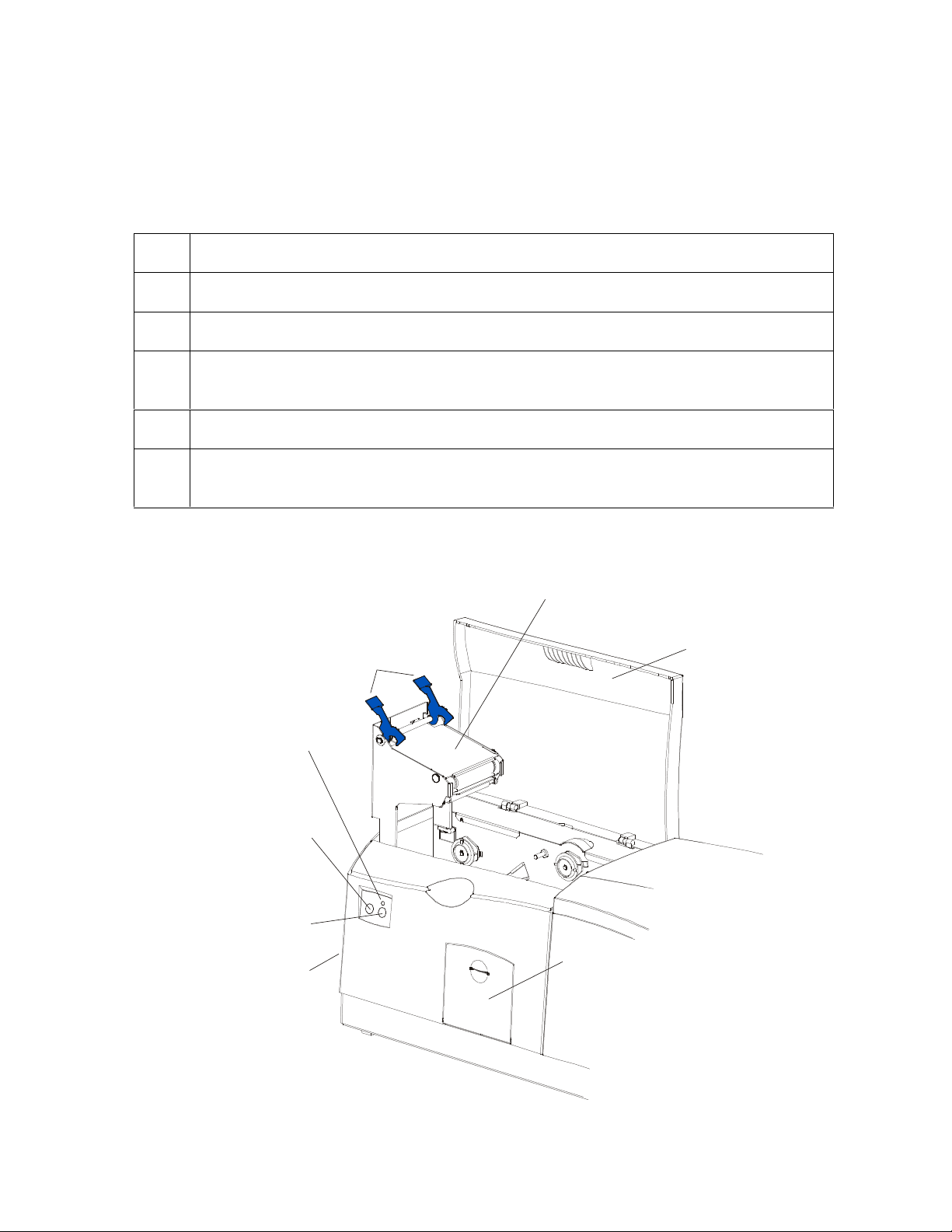
Securing
Latches
Lamination
LED Light
Cancel
Button
Resume
(pause) Button
Card Output
Hopper
Continued on the next page
Top Cover
Rejection
Card Hopper
DTC500 Series Card Printer/Encoders User Guide (Rev. 6.0)
xvi
Page 17

RESTRICTED USE ONLY FARGO Electronic, Inc.
Reviewing the Lamination Module Sequence of Operations (continued)
Step Process
6 The Card Feed Motor and the Lamination Ribbon Motor activate for the length of
the card.
7 The Lamination Roller Lift Motor cycles until Lamination Roller Lift Sensor detects
state change.
8 The card is fed back to the Flipper Table.
9 The Flipper Table Clutch engages.
10 The Flipper Table Motor activates until the Card is inverted based on the Flipper
offset setting.
11 The Flipper Table Clutch disengages.
12 The card is fed off the Flipper Table.
13 The Flipper Table Clutch engages.
14 The Flipper Table Motor activates until the Flipper Table is homed.
15 The Flipper Table Clutch disengages.
16 Repeat Steps 2 through 7.
17 The card is fed out of the Printer.
DTC500 Series Card Printer/Encoders User Guide (Rev. 6.0)
xvii
Page 18

RESTRICTED USE ONLY FARGO Electronic, Inc.
Reviewing the Lamination Module Boot up Sequence
Step Process
1 The Lamination Headlift turns until head up position is returned from Headlift
Sensor.
2 The Lamination Ribbon motor activates to determine the presence of a roll of
lamination.
3 The Lamination Flipper table homes itself.
4 The Card sensor checks for the presence of a card and ejects it if found.
DTC500 Series Card Printer/Encoders User Guide (Rev. 6.0)
xviii
Page 19

RESTRICTED USE ONLY Fargo Electronics, Inc.
Table of Contents
Section 1: Specifications_________________________________________________________ 6
Reviewing the DTC500 Series Printers Overview table ________________________________________6
Regulatory Compliances ________________________________________________________________7
Agency Listings_______________________________________________________________________8
Technical Specifications ________________________________________________________________8
Functional Specifications ______________________________________________________________13
Printer Components: LCD display to Parallel Interface Port_________________________________15
Printer Components: LCD and Softkey Control Pad_______________________________________19
Printer Components: Centronics-Type Parallel Interface ___________________________________24
Printer Components: Print Ribbons ____________________________________________________25
Printer Components: Embedded Fonts and Bar Codes _____________________________________25
Printer Components: Blank Cards _____________________________________________________26
Reviewing the upgraded 81754 PVC Cards ______________________________________________27
Printer Components: Card Input and Output Hoppers______________________________________29
Printer Components: Lamination Roller ________________________________________________30
Reviewing the Card Lamination Module __________________________________________________31
Determining the Ready Status of the Card Lamination Module_______________________________32
Reviewing the Lamination Top Cover and Station_________________________________________33
Reviewing the Securing Latches and Lamination LED light _________________________________34
Reviewing the Cancel button _________________________________________________________35
Reviewing the Resume (pause) button __________________________________________________36
Reviewing the Rejection Card Hopper and Card Output Hopper______________________________37
Reviewing the Module and Printer interaction____________________________________________38
Reviewing the Module and LCD display interaction _______________________________________39
Reviewing the Module’s Programmed Default Temperature_________________________________40
Reviewing the Laminator Temperature Adjustment________________________________________41
Reviewing the Overlaminates ___________________________________________________________42
Reviewing the Thermal Transfer Film and PolyGuard Overlaminates__________________________42
Reviewing the CR-90 or CR-100 Patch Size _____________________________________________43
Reviewing the Overlaminate Design ___________________________________________________43
Reviewing the Visual Security Solutions __________________________________________________44
VeriMarkTM Cards - 2-D holographic foil application _____________________________________44
Custom HoloMarkTM Cards _________________________________________________________44
Visual Security - Card Stock Part Numbers ______________________________________________44
Visual Security - Fargo Certified Overlaminates (Special Order in 50 quantity minimum)__________44
Visual Security Card Stock - Tolerances ________________________________________________45
VeriMarkTM - Application Specifications_______________________________________________45
HoloMarkTM and Custom HoloMarkTM - Application Specifications ________________________45
Section 2: General Troubleshooting ______________________________________________ 46
Reviewing the LCD display and LED light_________________________________________________46
Troubleshooting the LCD Messages____________________________________________________46
Verifying the Encoding Settings for DTC500 Series Card Printer and Encoders__________________53
Verifying Encoder Settings for DTC 510/DTC 515 (Symptom A) ____________________________54
Verifying Encoder Settings for DTC 510/DTC 515 (Symptom B) ____________________________54
Verifying the Encoding Settings for the DTC 520/DTC 525 _________________________________58
Communications Errors________________________________________________________________62
Resolving the Communication Errors___________________________________________________62
Card Feeding Errors __________________________________________________________________67
Resolving the Card Feeding Errors_____________________________________________________67
Resolving the Card Jam on the Flipper Table_____________________________________________70
Resolving the Card Hopper Jam Error Message___________________________________________72
Resolving the Card Hopper Empty Error Message_________________________________________73
Encoding Errors______________________________________________________________________74
DTC500 Series Card Printer/Encoders User Guide (Rev. 6.0)
1
Page 20

RESTRICTED USE ONLY Fargo Electronics, Inc.
Resolving the No Magnetic Encoder Error Message _______________________________________74
Resolving the No ENC Response Error Message__________________________________________74
Resolving the Failed Magnetic Encode Error Message _____________________________________75
Resolving the No Prox Encoder Error Message ___________________________________________75
Resolving the No Smart Encoder Error Message __________________________________________76
Resolving the Failed Smart Encode Error Message ________________________________________76
Removing the Card Jam in the Printer’s Magnetic Encoding Area ____________________________77
Removing the Card Jam in the Printer’s Smart Card Encoding Area___________________________78
Resolving the Printer not reading Encoded Magnetic Track Data _____________________________79
Resolving the Magnetic Stripe Data being printed on a Card problem _________________________81
Printing Process Errors ________________________________________________________________82
Resolving the Ribbon Alignment Error Message__________________________________________82
Resolving the Print Ribbon Error Message ______________________________________________83
Resolving the Print Ribbon Out Error Message ___________________________________________83
Resolving the Ribbon Jam/Broke Error Message__________________________________________83
Resolving the Wrong Print Ribbon Error Message ________________________________________84
Resolving the Unknown Ribbon Type Error Message ______________________________________85
Resolving the Headlift Error Message __________________________________________________86
Resolving the Printer pausing between panels error________________________________________87
Resolving the Printhead Temp Error Message ____________________________________________88
Resolving the Flipper Alignment Error Message __________________________________________89
Firmware Errors _____________________________________________________________________90
Resolving the Update Firmware Now __________________________________________________90
Resolving an Upgrade Failed error_____________________________________________________90
Resolving a Program Exception Error __________________________________________________93
Diagnosing the Image Problems _________________________________________________________94
Resolving the Pixel failure problems ___________________________________________________94
Resolving the Card surface debris problems _____________________________________________97
Resolving the incorrect Image Darkness problems _______________________________________100
Resolving the Ribbon wrinkle problems _______________________________________________103
Resolving the excessive Resin Printing problems ________________________________________105
Resolving the incomplete Resin Printing problems _______________________________________107
Resolving the cut off or off-center Card Image problems __________________________________109
Resolving the poor Image Quality problems ____________________________________________110
Printing a Test Image ________________________________________________________________111
Reviewing the Gray/Align YMC/K Self-Test ___________________________________________111
Reviewing the Color/Resin YMCK Self-Test ___________________________________________112
Reviewing the Color Bars YMC Self-Test ______________________________________________112
Reviewing the Card Count Self-Test __________________________________________________113
Reviewing the Magnetic Test option __________________________________________________113
Section 3: Card Lamination Module ____________________________________________ 114
Safety Messages (review carefully)______________________________________________________114
Loading the Overlaminate_____________________________________________________________115
Adjusting the Card Lamination Module __________________________________________________118
Adjusting the Card Flattener_________________________________________________________118
Adjusting the Card Guide Rail _______________________________________________________120
Adjusting the Internal Card Guide ____________________________________________________124
Attaching the Card Lamination Module ________________________________________________126
Section 4: Printer Adjustments_________________________________________________ 132
Safety Messages (review carefully)______________________________________________________132
Adjusting the Internal Card Guide ____________________________________________________133
Printer Driver options ________________________________________________________________135
Using the Device options tab___________________________________________________________135
Adjusting for the Ribbon Type_______________________________________________________136
Adjusting for the Color matching _____________________________________________________137
DTC500 Series Card Printer/Encoders User Guide (Rev. 6.0)
2
Page 21

RESTRICTED USE ONLY Fargo Electronics, Inc.
Adjusting for the Resin Dither _______________________________________________________138
Using the Print Both Sides option (DTC520/DTC525 only) ________________________________139
Using the Split 1 Set of Ribbon Panels option (DTC520/DTC525 only) _______________________140
Using the Print Back Side First option _________________________________________________141
Using the Print on Back Side Only option (DTC520/DTC525 only) __________________________142
Using the Rotate Front by 180 Degrees option___________________________________________143
Using the Rotate Back by 180 Degrees option (DTC520/DTC525 only)_______________________144
Using the Buffer Single Card option __________________________________________________145
Using the Link Card to Print Job option________________________________________________146
Using the Disable Printing option_____________________________________________________147
Using the Image Color tab_____________________________________________________________148
Using the K Panel Resin tab ___________________________________________________________152
Selecting the Full Card with the K Panel Resin tab _______________________________________153
Selecting the Defined Area(s) with the K Panel Resin tab __________________________________154
Selecting the Undefined Area(s) with the K Panel Resin tab ________________________________155
Defining the Area to activate the Card Grid _____________________________________________156
Measuring the Total Card area _______________________________________________________157
Defining the positioning of the area on the Card _________________________________________159
Selecting the Print YMC under the K and Print K Only options _____________________________161
Using the Magnetic Encoding tab _______________________________________________________163
Using the Encoding Mode option _____________________________________________________164
Encoding the Mode/Coercivity/Magnetic Track Selection__________________________________166
Using the Magnetic Track Selection option _____________________________________________168
Reviewing the Enable MLE Support checkbox __________________________________________169
Using the Magnetic Track options ____________________________________________________170
Using the Bit Density radio buttons ___________________________________________________171
Using the Character Size radio buttons_________________________________________________171
Using the ASCII Offset ____________________________________________________________172
Using the LRC Generation radio buttons _______________________________________________173
Using the Character Parity radio buttons _______________________________________________173
Using the Verification option ________________________________________________________174
Reviewing the Shift Data Left _______________________________________________________175
Reviewing the ISO Track Locations___________________________________________________176
Reviewing the Sample String ________________________________________________________176
Sending the Track Information_______________________________________________________177
Reviewing the ASCII Code and Character Table_________________________________________178
Using the Overlay/Print Area tab _______________________________________________________179
Using the Overlay/Print Area dropdown menu __________________________________________180
Using the Overlay/Print Area ________________________________________________________181
Using Security Options (Visual Security Solutions)_______________________________________187
Selecting Orientation - Landscape under Card tab ________________________________________188
Selecting the Visual Security Solutions dropdown menu (A to D) ___________________________189
Selecting Orientation - Portfolio under Card tab _________________________________________190
Selecting the Visual Security Solutions dropdown menu (E to H)____________________________191
Selecting the VeriMark radio button __________________________________________________192
Selecting the HoloMark radio button __________________________________________________193
Reviewing the Custom VeriMark Card ________________________________________________194
Reviewing the Custom HoloMark Card ________________________________________________195
Using SmartShield Area dropdown menu ______________________________________________196
Using the Card tab___________________________________________________________________197
Selecting the Card Size_____________________________________________________________198
Using the Card Hopper Selection (DTC515/DTC525 only) option ___________________________200
Reviewing the Orientation __________________________________________________________203
Specifying the Copies______________________________________________________________203
Using the Test Print button__________________________________________________________204
Clicking on the About button ________________________________________________________205
DTC500 Series Card Printer/Encoders User Guide (Rev. 6.0)
3
Page 22

RESTRICTED USE ONLY Fargo Electronics, Inc.
Using the Image Position button______________________________________________________206
Using the Lamination tab (only with Card Lamination Module) _______________________________209
Selecting the Lamination Position ____________________________________________________210
Selecting the Lamination Side _______________________________________________________211
Selecting the Lamination Type_______________________________________________________212
Selecting the Lamination Type_______________________________________________________213
Adjusting the Transfer Dwell Time and Transfer Temperature ______________________________214
Selecting the Sensors button and Defaults button_________________________________________214
Calibrating the Card Lamination Module’s Lamination Sensor______________________________215
Section 5: Cleaning___________________________________________________________ 216
Safety Messages (review carefully)______________________________________________________216
Cleaning the Printhead (850102) _____________________________________________________217
Replacing the Card Cleaning Tape____________________________________________________218
Cleaning the Platen and Card Feed Rollers _____________________________________________220
Cleaning the Platen________________________________________________________________223
Cleaning the Printer's Exterior _______________________________________________________224
Cleaning the Printer's Interior________________________________________________________224
Cleaning the Magnetic Encoder ______________________________________________________226
Section 6: Packing the DTC500 Card Printer _____________________________________ 229
Section 7: Board Level Diagnostics ______________________________________________ 230
Board Errors _______________________________________________________________________230
Resolving the EE Memory Error _____________________________________________________230
Resolving the EE Checksum Error____________________________________________________230
Resolving the DRAM Memory Error__________________________________________________231
Resolving the RAM Memory Error ___________________________________________________231
Resolving the FPGA Error __________________________________________________________231
Sensor Testing______________________________________________________________________232
Reviewing the Sensor Location and Voltages ___________________________________________233
Reviewing the Sensor Layout on Ribbon Sensor array ____________________________________234
Section 8: LCD On-Line Menu Navigation _______________________________________ 235
Entering the LCD Menu and selecting an Option ___________________________________________235
Using the Softkey and Scroll buttons __________________________________________________236
Accessing the Menu Option Structure Tree________________________________________________236
Selecting from the Menu Option Structure Tree__________________________________________237
Using the LCD Menu ________________________________________________________________238
Printing the Self-test_______________________________________________________________238
Reviewing the Gray/Align YMC (DTC510/515) and Gray/Align YMC/K (DTC520/525) Self-Test _239
Reviewing the Color/Resin YMCK Self-Test ___________________________________________239
Reviewing the Card Count YMC Self-Test _____________________________________________240
Reviewing the Standard Resin Self-Test _______________________________________________240
Using the Magnetic Test option (only with Magnetic Encoding Module) ______________________241
Setting up the Printer ______________________________________________________________241
Print TOF and Print EOF Alignment Procedures ___________________________________________242
Preparing to Adjust the Print TOF and Print EOF ________________________________________243
Setting the Print TOF ______________________________________________________________243
Setting the Print EOF ______________________________________________________________244
Adjusting the Ribbon Tension _______________________________________________________246
Setting the Printhead Resistance______________________________________________________247
Adjusting the Image Darkness _______________________________________________________248
Changing the Encoder Settings_______________________________________________________249
Adjusting the Magnetic TOF ________________________________________________________250
Changing the Hopper Settings _______________________________________________________252
Changing the BAUD Rate Settings ___________________________________________________253
DTC500 Series Card Printer/Encoders User Guide (Rev. 6.0)
4
Page 23

RESTRICTED USE ONLY Fargo Electronics, Inc.
Adjusting the Flipper Offset _________________________________________________________253
Viewing the Report Supplies ________________________________________________________254
Using the Show the Error Count Tool _________________________________________________254
Showing the Card Count____________________________________________________________255
Selecting the System Upgrade (Firmware Upgrade) ______________________________________255
Section 9: Firmware Updates __________________________________________________ 256
Firmware Updater Application Program__________________________________________________256
Downloading Firmware Updates________________________________________________________258
Updating the Printer's Firmware ________________________________________________________259
Updating the Main Firmware ________________________________________________________259
Updating the LCD Firmware ________________________________________________________262
Section 10: DTC500 Enhancement Kit Instructions Overview _______________________ 264
Reviewing the Parts (included with the Kit; 1 set per Card Printer)___________________________264
Reviewing the required Tools________________________________________________________265
Reviewing the required Media supplies ________________________________________________265
Updating the Process Strategy__________________________________________________________266
Determining the Card Printer qualifications for the Update_________________________________266
Unpacking the Card Printer _________________________________________________________267
Removing the Printer's main plastic casing _____________________________________________268
Inspecting the Drive Pulley _________________________________________________________269
Installing the Push-Clip onto the Drive Roller ___________________________________________271
Removing and installing the Card Feed Roller (D850415) _________________________________272
Installing the Sensor Holder _________________________________________________________274
Installing the new Card Input Hopper in the single Hopper units (DTC510/520) ________________277
Installing the new Card Input Hopper in the dual Hopper units (DTC515/525)__________________280
Applying the Close Door While Printing Label (L000188) _________________________________283
Applying the Ribbon Loading Label (L000108) _________________________________________284
Replacing the plastic Printer casing ___________________________________________________285
Powering up the Unit and confirming its Ready status_____________________________________286
Upgrading the Firmware to Version 1.5.1 ______________________________________________287
Confirming the Printer operations ____________________________________________________290
Removing the Media from the Printer _________________________________________________298
Repackaging the Printer ____________________________________________________________298
Section 11: Fargo Technical Support____________________________________________ 300
Contacting Fargo Technical Support_____________________________________________________300
Reading the Serial Numbers on a Fargo printer ____________________________________________301
Finding out when a Fargo Card Printer was manufactured _________________________________301
Reviewing Example No. 1: Serial Number 80453289_____________________________________301
Reviewing Example No. 2: Serial Number A1280224 ____________________________________301
Section 12: Reviewing Spare Parts Lists _________________________________________ 302
Reviewing the Spare Parts List for DTC500 Series Card Printer_____________________________302
Reviewing the Spare Parts List for the DTC500 LAM_____________________________________302
Glossary of Terms ____________________________________________________________ 303
Index_______________________________________________________________________ 323
DTC500 Series Card Printer/Encoders User Guide (Rev. 6.0)
5
Page 24

RESTRICTED USE ONLY Fargo Electronics, Inc.
Section 1: Specifications
The purpose of this section is to provide the User with specific information on the Regulatory
Compliances, Agency Listings, Technical Specifications and Functional Specifications for the
DTC500 Series Card Printer/Encoders User Guide (Rev. 6.0).
Reviewing the DTC500 Series Printers Overview
table
DTC500 Series Input
Hoppers
DTC510 (Single-Sided
Card Printer/Encoders)
DTC515 (Single-Sided
Card Printer/Encoders)
DTC515-LC (SingleSided Card
Printer/Encoders)
DTC520 (Dual-Sided
Card Printer/Encoders)
DTC525 (Dual-Sided
Card Printer/Encoders)
DTC525-LC (DualSided Card
Printer/Encoders)
1 100 N/A Optional N/A
2 200 Included Optional Optional
2 200 Included Optional Included
2 100 N/A Optional N/A
2 200 Included Optional Optional
2 200 Included Optional Included
Card
Capacity
Security Encoding
Modules
Lamination
Module
DTC500 Series Card Printer/Encoders User Guide (Rev. 6.0)
6
Page 25

RESTRICTED USE ONLY Fargo Electronics, Inc.
Regulatory Compliances
Term Description
CSA The Printer manufacturer has been authorized by UL to represent the
Card Printer as CSA Certified under CSA Standard 22.2.
File Number: E145118
FCC The Card Printer complies with the requirements in Part 15 of the FCC
rules for a Class B digital device. (Note: These requirements are
designed to provide reasonable protection against harmful interference
in a residential installation.)
If equipment operation in a residential area causes unacceptable
interference to radio and TV reception, the operator is required to take
whatever steps are necessary to correct the interference.
ITS-EMC The Card Printer has been tested and complies with EN55022 Class B:
1995 and EN82082-1: 1997 standards for EMI emissions.
(Note: Based on the above testing, the Printer manufacturer certifies
that the Card Printer complies with all current EMC directives of the
European Community and has placed the CE mark on the Card
Printer.)
License Number: J99032510
TÜV-GS The Card Printer has been tested and complies with IEC950 and bears
the TÜV-GS mark.
License Number: S9971826
UL The Card Printer is listed under UL 1950 INFORMATION
TECHNOLOGY EQUIPMENT.
File Number: E145118, Volume 1, Section 15
DTC500 Series Card Printer/Encoders User Guide (Rev. 6.0)
7
Page 26

RESTRICTED USE ONLY Fargo Electronics, Inc.
Agency Listings
Term Description
Emissions
Standards
Safety
Standards
EMC: ITS (EN 55022 Class B:1995), FCC Class B, EN 50082-1:1997,
BSMI, CRC c1374, CE and CCIB
UL 1950, CSA C2.2 (No.950-95) and TüV-GS (IEC-950), CE and
CCIB.
Technical Specifications
Term Description
Accepted
Standard Card
Size
Accepted Card
Thickness
Accepted Card
Types
Accepted Card
Compositions
CR-79 Adhesive Back: 3.303 in. x 2.051 in. (83.9mm x 52.1mm)
(cannot be laminated with DTC515-LC or DTC525-LC)
CR-80: 3.375 in. x 2.125 in. (85.6mm x 54mm) (corresponds to ID1)
.010 in. (10 mil) to .050 in. (50 mil) (.254mm to 1.27mm); unless
laminating.
HID Proximity Cards, Mifare Contactless Smart Cards and Contact
Smart Cards
PVC or polyester cards with polished PVC finish; monochrome resin
required for 100% polyester cards.
Barcodes Code 39, Code 128 B & C with and without check digit (available with
embedded font and bar code option): 2 of 5, UPC-A, EAN 13 and
PDF-417 2D bar code and other symbologies (available via Windows
driver).
Card Input
Hopper Capacity
Card Output
Hopper Capacity
DTC510/520: Single-stack hopper, 100 cards (30 mil); auto or
manual feed
DTC515/525: Dual-stack hopper, 200 cards (30 mil); auto or
manual feed
DTC515-LC/525-LC: Dual Hopper; 200 cards (.030”); auto or
manual feed
100 cards (30 mil)
Continued on the next page
DTC500 Series Card Printer/Encoders User Guide (Rev. 6.0)
8
Page 27

RESTRICTED USE ONLY Fargo Electronics, Inc.
Technical Specifications (continued)
Term Description
Card Cleaning Removable card cleaning cartridge with replaceable cleaning tape.
Colors Up to 16.7 million colors and 256 shades per pixel.
Dimensions DTC510/515/520/525: 10.75 in. H x 18.5 in. W x 11 in. D (273mm x
470mm x 279mmD).
DTC515-LC/525-LC: 10.75 in. H x 30.5 in. W x 11 in. D (273mm x
775mm x 279mmD).
LC Module: 10.25” H x 30” W x 11”D/260mm H x 762mm W x
279mmD
Display SmartScreen LCD Control Panel; LED display on Card Lamination
Module.
Fonts Resident Swiss Bold 8, 10, 12, 14, 16, 18 and 22 are available with
embedded font and bar code option.
TrueType fonts are available via the Windows driver.
Humidity 20% to 80% Non-Condensing.
Interface
Centronics Parallel, IEEE 1284 compliant
Optional EIA-232C serial interface (for embedded fonts and bar
codes option)
Optional USB-to-Parallel Interface Cable (Windows
98/Me/2000/XP)
Memory 4 MB RAM
Operating
65ºF to 80ºF (18ºC to 27ºC).
Temperature
Print Area
CR-80 edge-to-edge: (3.37 in. x 2.12 in./85.5mm x 53.5mm)
CR-79: (3.3 in. x 2.051 in./83.8mm x 52.1mm)
Continued on the next page
DTC500 Series Card Printer/Encoders User Guide (Rev. 6.0)
9
Page 28

RESTRICTED USE ONLY Fargo Electronics, Inc.
Technical Specifications (continued)
Term Description
Print Speed –
Batch Mode
DTC510/515: 7 seconds per card/514 cards per hour (K)*
DTC510/515: 12 seconds per card/300 cards per hour (BO)*
DTC510/515: 27 seconds per card/133 cards per hour
(YMCKO)*
DTC520/525: 35 seconds per card/102 cards per hour
(YMCKOK)*
DTC515-LC/525-LC: 30 seconds per card/133 cards per hour
(YMCK/lamination)*
DTC525-LC: 36 seconds per card /102 cards per hour
(YMCKK/lamination)*
*Indicates the print Ribbon type and the number of Ribbon panels
printed where Y=Yellow, M=Magenta, C=Cyan, K=Resin Black,
B=Dye-Sublimation Black and O=Overlay.
Print speeds do not include the time needed for the PC to process
the image.
Process time is dependent on the size of the file, the CPU,
amount of RAM and the amount of available resources at the time
of the print.
Print speed indicates an approximate batch print speed and is
measured from the time a card feeds into the Printer to the time it
ejects from the Printer. (Note: The single card print speeds will
be slower than the batch print speeds listed above since batch
print speed is enhanced by the Printer's multi-tasking capabilities
when printing multiple cards in succession.)
Printing Method Dye-Sublimation/Resin Thermal Transfer.
Overlaminate
Options (for LC)
Thermal Transfer Overlaminate, .25 mil thick
PolyGuard Overlaminate, 1.0 mil and .6 mil thick
All overlaminates available in clear, holographic globe design or
custom holographic design
Continued on the next page
DTC500 Series Card Printer/Encoders User Guide (Rev. 6.0)
10
Page 29

RESTRICTED USE ONLY Fargo Electronics, Inc.
Technical Specifications (continued)
Term Description
Options
Encoding Options
Printer Cleaning Kit
External Print Server (Windows only; required for stand-alone
networking of printer/encoders)
Card Lamination Module (DTC515 and DTC525 only)
Embedded Fonts and Bar Codes to print from AS/400, mainframe
and other systems
o Code 39, Code 128 B & C with and without check digit
o 2 of 5
o UPC-A
o EAN 13
o PDF-417 2D bar code and other symbologies available via
Windows driver
o Resident: Swiss Bold 8, 10, 12, 14, 16, 18 and 22
ISO Magnetic Stripe Encoding Module, dual high- and low-
coercivity, Tracks 1, 2 and 3
JIS II Magnetic Stripe Encoding Module
E-Card Docking Station (required for all e-card options or 3rd party
Smart card encoding)
Fargo Certified
Supplies
Printing
Resolution
Contactless Smart Card Encoder (MIFARE)
Contact Smart Card Encoder reads from and writes to all
ISO7816-1/2/3/4 memory and microprocessor smart cards (T=0,
T=1) as well as synchronous cards
Prox Card Encoder (HID read-only); I class
Fargo Card Printer/Encoders require highly specialized media to
function properly. To maximize printed card quality, printhead life and
printer/encoder reliability, use only Fargo Certified Supplies. Fargo
warranties are void, where not prohibited by law, when non-Fargo
Certified Supplies are used.
Up to 16.7 million colors and 256 shades per pixel.
300 dpi (11.8 dots/mm)
Continued on the next page
DTC500 Series Card Printer/Encoders User Guide (Rev. 6.0)
11
Page 30

RESTRICTED USE ONLY Fargo Electronics, Inc.
Technical Specifications (continued)
Term Description
Print Ribbon
options
Full Color with resin black and overlay panel, YMCKO, 400 prints
Full Color with two resin black panels and overlay panel,
YMCKOK, 350 prints
Full Color, no resin black, no overlay panel, YMC, 700 prints,
must be used with overlaminate
Full Color with resin black, no overlay panel, YMCK, 500 prints,
must be used with overlaminate
Full Color with 2 resin black panels, no overlay panel, YMCKK,
400 prints, must be used with overlaminate
Dye-Sublimation black, BO, 500 prints
Resin black, green, blue, red, white, silver, gold, scratch-off, 1000
prints
Security Features SmartGuard, SmartShield, Card Hopper Lock (available only on
DTC515/525/515-LC/525-LC)
Software Drivers
Windows 95/ 98/ ME/ NT/ 2000/XP; Optional Macintosh (not
available on the DTC515-LC/525-LC).
Supply Voltage
DTC510/515/520: 100-240 VAC, 1.2A
DTC525/515-LC/525-LC: 100-240 VAC, 2.2A
Supply
50 Hz/60 Hz.
Frequency
System
Requirements
IBM-PC or compatible. Windows 95/ 98/ ME/ NT/ 2000/XP. Pentium™
class 133 MHz computer with 32 MB of RAM or higher, 200 MB free
hard disk space or higher and ECP Parallel Port with DMA access.
Warranty Printer – One year; optional Extended Warranty Program (U.S. only)
Printhead – One year, unlimited pass with UltraCard Cards
Weight DTC510/515/520/525: 24 lbs. (10.8 kg).
DTC515-LC/DTC525-LC: 43 lbs./19.5kg
LC Module: 19 lbs./8.6 kg.
DTC500 Series Card Printer/Encoders User Guide (Rev. 6.0)
12
Page 31

RESTRICTED USE ONLY Fargo Electronics, Inc.
Functional Specifications
The card Printer utilizes two different, yet closely related printing technologies to achieve its
direct-to-card print quality for Dye-Sublimation and resin thermal transfer. The card Printer
will print from any IBM-PC® or compatible running Windows® 95/98/Me, Windows NT 4.0,
Windows 2000 or Windows XP.
The following describes how each of these technologies works:
Function Description
DyeSublimation
Dye-Sublimation is the print method the card Printer uses to produce
smooth, continuous-tone images that look photographic. (Note: This
process uses a dye-based Ribbon roll that is partitioned by a number of
consecutive color panels.)
Process Colors: The panels are grouped in a repeating Series of
three process colors - yellow, magenta and cyan (YMC), along the
entire length of the print Ribbon.
Panels: The Printer always prints the yellow panel first, followed by the
magenta panel and the cyan panel.
Printhead: As the print Ribbon passes beneath the Printhead,
hundreds of thermal elements within the Printhead heat the dyes on the
Ribbon. (Note: When these dyes are heated, they vaporize and diffuse
into the surface of the card. A separate pass is made for each of the
three color panels on the Ribbon.)
Color Shades: By combining the colors of each panel and by varying
the heat used to transfer these colors, it is possible to print up to 16.7
million different shades of color. (Note: This blends one color smoothly
into the next, producing photo-quality images with absolutely no dot
pattern.)
Dye-Diffusion Thermal Transfer: It is the process of heating a dye
suspended in a cellulous substrate until the dye can flow, diffusing into
the dye receptive surface of the card or InTM. This produces the image
in the surface of the card.
Continued on the next page
DTC500 Series Card Printer/Encoders User Guide (Rev. 6.0)
13
Page 32

RESTRICTED USE ONLY Fargo Electronics, Inc.
Functional Specifications (continued)
Function Description
Resin
Thermal
Transfer
Resin Thermal Transfer is the print method the Printer uses to print sharp
black text and crisp bar codes that can be read by both infrared and visiblelight bar code scanners.
Like Dye-Sublimation, this process uses the same thermal Printhead to
transfer color to a card from a resin-only print Ribbon or the resin black (K)
panel of a full color print Ribbon.
The difference, however, is that solid dots of resin-based ink are
transferred and fused to the surface of the card. (Note: This produces very
durable, saturated printing.)
Continued on the next page
DTC500 Series Card Printer/Encoders User Guide (Rev. 6.0)
14
Page 33

RESTRICTED USE ONLY Fargo Electronics, Inc.
Printer Components: LCD display to Parallel Interface Port
Component Description
Access Card
Slot
Card Thickness
Adjustment
Lever
Card Cleaning
Cartridge
Card Input
Hopper
Card Output
Hopper
Card Supply
Window
Card Input
Hopper Lock
The SmartGuard Access Card is inserted in this slot and is used with
the Printer's optional SmartGuard Security Feature.
Adjusts the Printer to feed varying card thicknesses.
Automatically cleans cards for higher print quality. (Note: Replace this
tape after every 3000 cards or as needed.)
Load blank cards into this hopper.
Stores printed cards; up to 100, 30 mil cards.
Check the current card supply at-a-glance, without having to open the
Card Hopper Door.
If using the DTC515 or DTC525 Card Printer, this lock allows you to
lock the Card Input Hopper Door to help prevent the theft of blank
cards.
If using the DTC510 or DTC520 Card Printers, this lock is not
available.
Exception Card
Slot
Insert a single exception card into this slot if you would like to print onto
a card other than those loaded in the Card Input Hopper.
LCD display Displays the current status of the Printer.
LED light Indicates Printer ON, OFF, pause and error conditions.
Continued on the next page
DTC500 Series Card Printer/Encoders User Guide (Rev. 6.0)
15
Page 34
RESTRICTED USE ONLY Fargo Electronics, Inc.
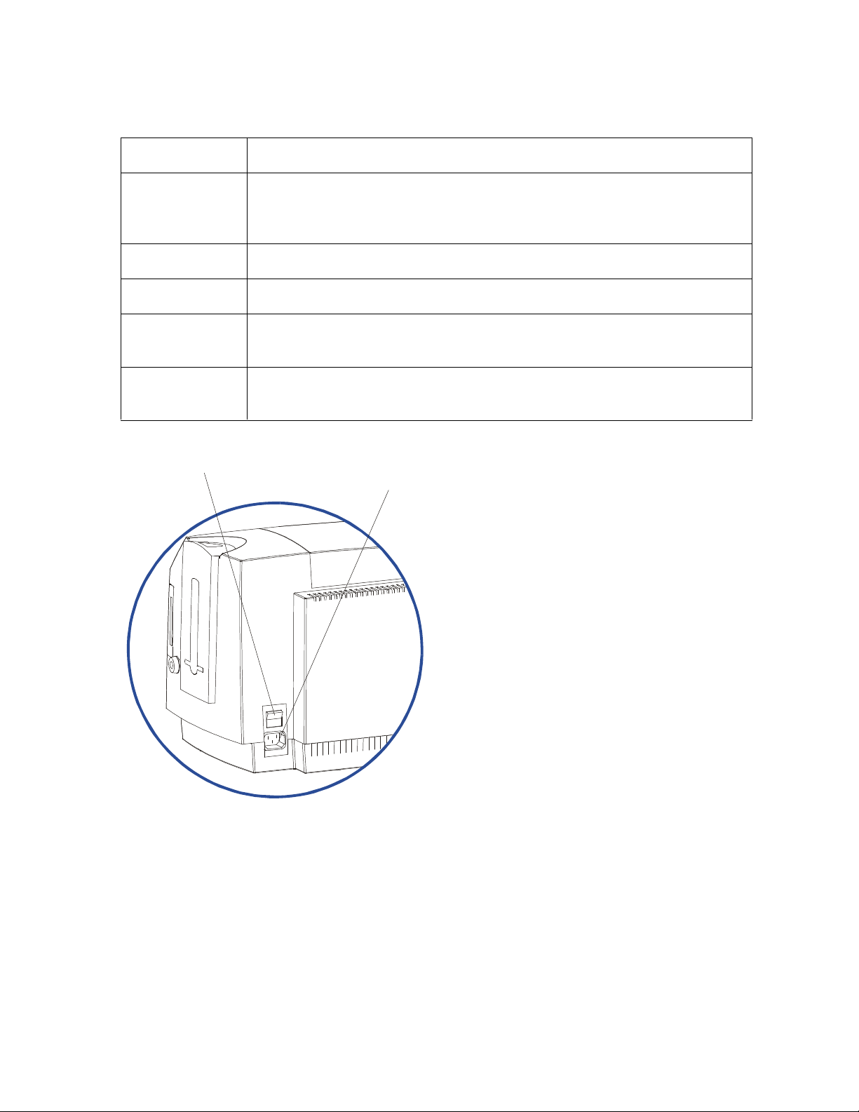
Power Port
Power Switch
Printer Components: LCD display to Serial Interface Port (continued)
Component Description
Printhead
This Print Station component actually does the printing. (Note: This
component is fragile and must not be bumped or touched with anything
other than a cleaning pen.)
Power Switch This switch turns the Printer power ON and OFF.
Power Port This port connects to the (included) power cord.
Securing
These latches lock the Print Station securely in place when closed.
Latches
Softkey Buttons The button function is displayed above the button. The buttons change
depending upon the Printer's mode of operation.
DTC500 Series Card Printer/Encoders User Guide (Rev. 6.0)
16
Page 35

RESTRICTED USE ONLY Fargo Electronics, Inc.
Parallel Interface Port
(Smart Card option only)
(Font / Bar Code option only)
Printer Components: LCD display to Serial Interface Port (continued)
Component Description
scroll buttons These buttons are used to scroll through menus and sub-menus and to
adjust certain menu options.
Parallel
Interface Port
Serial Interface
Port
Serial Interface
Port
This port connects to a Windows PC with a parallel cable.
For Smart Card option: This port is provided only if your Printer
includes an optional Smart Card Contact Station.
For Embedded Fonts and Bar Codes option: This port is provided
only if your Printer includes optional embedded fonts and bar codes
support.
Continued on the next page
Serial Interface Port
DTC500 Series Card Printer/Encoders User Guide (Rev. 6.0)
Serial Interface Port
17
Page 36

RESTRICTED USE ONLY Fargo Electronics, Inc.
LCD Display
Softkey Buttons
Card Cleaning Cartridge
Printer Components: LCD display to Serial Interface Port (continued)
Refer to the previous table.
Top Cover
Securing
Latches
Card Output
Hopper
Printhead
Print Station
LED Light
Scroll Buttons
Card Input Hopper
Card Supply Window
Exception Card Slot
Card Input
Hopper Lock
Access Card Slot
Card Thickness
Adjustment Lever
DTC500 Series Card Printer/Encoders User Guide (Rev. 6.0)
18
Page 37

RESTRICTED USE ONLY Fargo Electronics, Inc.
Printer Components: LCD and Softkey Control Pad
The Printer provides a four line, eighty (80) character LCD display that communicates helpful
information about the Printer's operation.
The top three lines of the LCD display will always be used to communicate print status,
error messages and menu options.
The bottom line of the LCD display will always be used to communicate the current
function of the Printer's softkey buttons.
This section describes how the LCD display and Softkey Control Pad work together.
Component Description
Softkey
Buttons
The Printer has three softkey buttons that appear below the LCD
display. (Note: Their current function is indicated by the words
appearing above them. This function will change according to the
Printer's current mode of operation.)
Press the corresponding softkey button for the correct selection.
(Note: If no word appears above a particular button, this indicates it
has no function in that particular mode of operation.)
Use the scroll buttons to scroll through help text, to navigate through
the Printer's menus and to adjust certain Printer settings. (Note: The
Printer has scroll buttons on its control pad located just to the right of
the LCD display.)
If scrolling through a list, this symbol will change to if you have
reached the bottom of the list or if you have reached the top.
LCD display The Printer's LCD display will change according to the Printer's current
mode of operation.
System Check
Screens
When the Printer is first powered ON, the Printer's system check screens
will briefly appear to:
Display and test the amount of installed Printer memory.
Align the print Ribbon.
Display the READY screen and current Firmware version.
Continued on the next page
DTC500 Series Card Printer/Encoders User Guide (Rev. 6.0)
19
Page 38

RESTRICTED USE ONLY Fargo Electronics, Inc.
Printer Components: LCD and Softkey Control Pad (continued)
Component Description
Ready/Printer
Open Screens
Print Status
Screen
Once the Printer has finished its system check and with the Print and
Transfer Stations closed, the Printer will display READY to indicate that
the Printer is ready for operation. (Note: The Printer will stay in this
mode until it receives a print job or it is turned OFF.)
If the Top cover and Printhead Arm are opened, the Printer Open screen
will appear.
Press either the Forward or Back buttons to move the Printer's card
path Rollers in the indicated direction.
In any of these screens, the Printer will always display the Menu option
above the center softkey button.
Press this button to access the Printer's menu options. (Note: The
Menu option is available only in the Ready/Printer Open screens.)
During operation, the LCD will indicate the current Print Status by
showing you the area of the Printer that is active. It does this by
displaying the following icons on the second line:
FDR Indicates the Feeder Station is feeding a blank card into the
Printer.
ENC Indicates the Encode Station is encoding a card (appears only if
you are using a Printer with an optional built-in Encoding Module).
PRT Indicates the Print Station is printing onto the film.
LAM indicates the Lamination Station is applying an overlaminate to a
card (appears only if using a Printer equipped with the optional Card
Lamination Module. See Section 3: Card Lamination Module on page
114.
Since the Printer is capable of performing several of these functions
simultaneously, one or all of these icons may appear at once, depending
on if you are printing just one card or a batch of cards.
The Print Status screen always displays Cancel in the lower left and
Pause in the lower right.
Continued on the next page
DTC500 Series Card Printer/Encoders User Guide (Rev. 6.0)
20
Page 39

RESTRICTED USE ONLY Fargo Electronics, Inc.
Printer Components: LCD and Softkey Control Pad (continued)
Component Description
The Cancel
button
Use this button to cancel print jobs and reset the Printer for the next print
job.
This Cancel function will cancel all print jobs in the Printer and will
completely reset the Printer. In this case, be sure to cancel the print
jobs from the PC before pressing YES.
Caution: To avoid this, select the Print in Single Card Mode
option from the Printer driver before sending the next print job. If a card is
left within the Printer after a print job is canceled, it will automatically be
ejected.
Pause button Use this button to pause the Printer at any time during operation. (Note:
The Printer will always finish its current task before pausing. When the
Printer is paused, the LED light will flash and the Pause softkey button
will change to Resume.)
Press Resume to continue Printer operation.
Continued on the next page
DTC500 Series Card Printer/Encoders User Guide (Rev. 6.0)
21
Page 40

RESTRICTED USE ONLY Fargo Electronics, Inc.
LED Light
Printer Components: LCD and Softkey Control Pad (continued)
Component Description
LED light This light works in conjunction with the Printer's LCD display to help
communicate the Printer's current status. (Note: It is especially effective
when the User is too far away from the Printer to read the LCD display.)
The following explains how to interpret both LED lights on the exterior of
the Printer.
Off: Indicates the Printer power is OFF.
Solid GREEN: Indicates the Printer is powered ON and ready for
operation.
Flashing GREEN: Indicates a Printer ERROR or ATTENTION
condition. (Note: Refer to the Printer's LCD display for information.)
Continued on the next page
DTC500 Series Card Printer/Encoders User Guide (Rev. 6.0)
22
Page 41

RESTRICTED USE ONLY Fargo Electronics, Inc.
Printer Components: LCD and Softkey Control Pad (continued)
Component Description
Error Screens Your Printer is capable of communicating two similar yet different types
of message screens:
The first is called an ERROR screen. This screen appears if an error
occurs and will completely stop Printer operation.
In this case, the LCD will display ERROR on the first line and a brief
description of the error on the second line.
If multiple errors occur at the same time, the first line will display
ERROR 1 of 2 or whatever the total number of errors may be.
To see the other error(s), use the scroll keys.
Press the HELP button to bring up the help screen explaining the
nature of the error and how to correct it. If necessary, use the scroll
buttons to scroll down the paragraph of help text.
Press QUIT when you are done reading. Once the error is corrected,
resume operation or reset the Printer according to how you were
instructed in the help screen.
Attention
Screens
The second type of prompt is called an ATTENTION screen.
This screen will not stop Printer operation and serves to communicate
helpful reminder (e.g., when running low on print supplies).
This screen communicates any other Printer conditions of which you
should be aware.
In this case, the LCD will display ATTENTION on the first line and a brief
description of the condition on the second line.
If multiple messages need to be communicated at the same time, the
first line will display ATTENTION 1 of 2 or whatever the total number
of messages may be.
Like error messages, help text explaining the particular condition can
also be accessed by pressing the HELP button.
DTC500 Series Card Printer/Encoders User Guide (Rev. 6.0)
23
Page 42

RESTRICTED USE ONLY Fargo Electronics, Inc.
WIRE DIAGRAM
19 Through 30
19 Through 25
141325
Printer Components: Centronics-Type Parallel Interface
The card Printer is equipped with a standard 8-bit Centronics-type parallel interface port.
(Note: This communication port is the means through which the Printer receives data from
the computer. This section describes the pin assignments and signal specifications for this
port.)
If your Printer is equipped with optional embedded font and bar code support, it will
include a DB-9, RS-232c, male serial connector. This port is used only for applications
where the Printer will be connected to a terminal device such as an AS400.
If your Printer is equipped with an optional E-Card encoding Station, it will include a DB-
9, female serial connector. This port is used only for applications where the Printer will be
connected to an external Smart Card interface.
The Printer's parallel interface connector is a standard 36-pin Amp type with two metal-wire
retaining clips and is ECP (Extended Capabilities Port) compatible. (Note: It mates with a
standard, bi-directional PC to Printer parallel cable. For best results, keep the interface cable
to under 6 feet in length.)
19
36
PIN 1
18
DB36P
DB25P
1 1
2 2
3 3
4 4
5 5
6 6
7 7
8 8
9 9
10 10
11 11
12 12
13 13
14 14
32 15
31 16
36
17
Shell Shell
PIN 1
DTC500 Series Card Printer/Encoders User Guide (Rev. 6.0)
24
Page 43

RESTRICTED USE ONLY Fargo Electronics, Inc.
Printer Components: Print Ribbons
The card Printer utilizes both Dye-Sublimation and/or resin thermal transfer methods to print
images directly onto blank cards. Since the Dye-Sublimation and the resin thermal transfer
print methods (each) provide their own unique benefits, print Ribbons are available in resinonly, Dye-Sublimation-only and combination Dye-Sublimation/resin versions.
This letter code indicates the type of Ribbon panel used with each Ribbon.
= Dye-Sublimation Yellow Panel
= Dye-Sublimation Magenta Panel
= Dye-Sublimation Cyan Panel
= Resin Black Panel
= Overlay Panel
Printer Components: Embedded Fonts and Bar Codes
The information in this section applies only if your Printer is configured with the embedded
fonts and bar codes option. See the DTC Online User’s Guide for additional information on
Embedded Fonts and Bar Codes.
This option provides select fonts and bar codes which are resident inside the Printer,
allowing you to print resin black text and bar codes directly from a terminal device such
as an AS400.
If printing from a standard Windows application, the included Printer driver supports any
TrueType font or bar code currently installed on your computer.
The existing and new Firmware updates for the DTC500 Series Card Printer/Encoders with
the Embedded Fonts and Bar Codes option (require Firmware Version 1.5.9) and without the
Embedded Fonts and Bar Codes option (require Firmware Version 2.0.0-b2) are described
here. See Technical Update No. 46 (dated 11/06/2002).
DTC500 Series Card Printer/Encoders with Embedded Fonts and Bar Codes: The
latest version of Firmware supported by the Card Printer/Encoders is Firmware Version
1.5.9. (Technician Note: The Card Printer/Encoders will not support Firmware Version
2.0.0-b2 or optional Card Lamination Module compatibility.)
DTC500 Series Card Printer/Encoders without Embedded Fonts and Bar Codes:
The latest version of Firmware supported by the Card Printer/Encoders is Firmware
Version 2.0.0-b2. (Technician Note: This version provides support for the optional Card
Lamination Module.)
DTC500 Series Card Printer/Encoders User Guide (Rev. 6.0)
25
Page 44

RESTRICTED USE ONLY Fargo Electronics, Inc.
Printer Components: Blank Cards
Caution: Never run cards with a contaminated, dull or uneven surface through the
Printer. Printing cards on this surface can lead to poor print quality and can greatly reduce
the life of the Printhead. Always store the card stock in its original packaging or in a clean,
dust-free container. Do not print onto cards that have been dropped or soiled. Printhead
damage caused by contaminated or poor quality cards will automatically void the Printhead's
factory warranty.
Type Description
Card Size The card Printer accepts standard CR-80 sized cards (3.375” L x 2.125”
W/85.6mm L x 54mm W) or CR-79 sized cards (3.303” L x 2.051” W/83.9mm
L x 52.1mm W) with a thickness of 10 mil to 50 mil. This does not apply for
the LC printers.
Card
Design
Card
Surface
UltraCard
Stock
The Printer will print onto any card with a clean, level and polished PVC
surface. (Note: Although the Printer is equipped with card cleaning Rollers,
it is very important to always print onto cards specifically designed for directto-card Dye-Sublimation printing.)
Suitable cards must have a polished PVC surface free of fingerprints, dust or
any other types of embedded contaminants.
Cards must have a completely smooth, level surface in order for the
Printer to achieve consistent color coverage.
Some types of Proximity cards, for example, have an uneven surface
which will inhibit consistent color transfer.
Some Smart Card chips are raised slightly above the cards surface,
which also results in poor color transfer.
Due to the importance of using high-quality blank cards, a factory-approved
card stock called UltraCard™ is available and recommended for best results.
UltraCard stock has a glossy PVC laminate on top and bottom and is
optically inspected to provide the cleanest, most scratch and debrisreduced cards possible.
Two types of these cards are available: UltraCard and UltraCard III.
UltraCard stock has a PVC core and offers medium card durability.
UltraCard III stock has a 40% polyester core and offers high durability.
Both types of UltraCards produce printed images with a glossy, photo-quality
finish.
DTC500 Series Card Printer/Encoders User Guide (Rev. 6.0)
26
Page 45
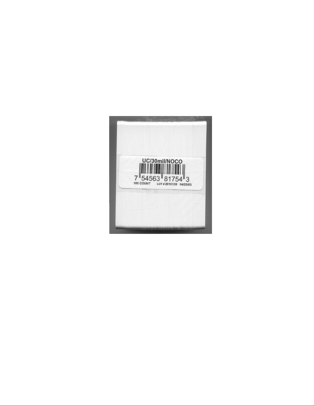
RESTRICTED USE ONLY Fargo Electronics, Inc.
Reviewing the upgraded 81754 PVC Cards
The upgraded 81754 PVC cards are designed for a sharper card image quality and for
reduced debris and defects on Fargo Card Printers. Carefully read these detailed notes and
instructions before applying this information to your Fargo printer or printers.
Technician Note 1: The new card lot number starts at Lot # 2010104 with date codes
that started on 04/01/2003. The photo (below) shows a lot number that starts after Lot #
2010104, indicating a new card lot number. The card lot number and date can be read
on the bar code label attached to the shrink-wrapped stack of 100 cards, as shown
below. All new Fargo printers with a serial number (S/N) starting with A320 will have
factory settings for these new 81754 PVC cards.
Technician Note 2: Do not use the new 81754 PVC card stock with Fargo laminating
printers/encoders. This same guideline is used for the existing 81754 PVC card stock.
Fargo recommends using the UltraCard III stock with the Fargo laminating
printers/encoders.
DTC500 Series Card Printer/Encoders User Guide (Rev. 6.0)
27
Page 46

RESTRICTED USE ONLY Fargo Electronics, Inc.
Reviewing the upgraded 81754 PVC Cards (continued)
Follow these two (2) instructions below:
1. Instruction for new 81754 PVC card stock: Increase the Printer Driver’s Dye-Sub
Intensity to print with the new 81754 PVC card stock on Fargo Card Printers (S/N A319
and older). See the chart provided below. See the appropriate Fargo service documents
for specific Printer Driver instructions.
Card New Printer (S/N A320 and
newer)
Old Printer (S/N A319 and
older)
New Card No Change Necessary Increase the Dye-Sub Intensity as
follows:
HDP®: N/A
Pro-LX/C25: 3 - 5 %
DTC500: 5 -10 %
C11/C16: 3 - 5 %
2. Instruction for existing 81754 PVC card stock: The Printer Driver’s Dye-Sub Intensity
setting may or may not need to be decreased to print existing card stock. See the chart
provided below. See the appropriate Fargo service documents for specific Printer Driver
instructions.
Technician Note 1: To control the brightness of the image, adjust the Dye-Sub
Intensity slide on the Image Color tab of the Printer Driver.
Technician Note 2: Moving the Dye-Sub Intensity slide to the left causes less heat
to be used in the printing process, thus generating a lighter print.
Card New Printer (S/N A320 and
Old Printer (S/N A319 and older)
newer)
Old Card Decrease the Dye-Sub Intensity
No Change Necessary
as follows:
HDP®: N/A
Pro-LX/C25: 3 - 5 %
DTC500: 5 - 10 %
C11/C16: 3 - 5 %
DTC500 Series Card Printer/Encoders User Guide (Rev. 6.0)
28
Page 47
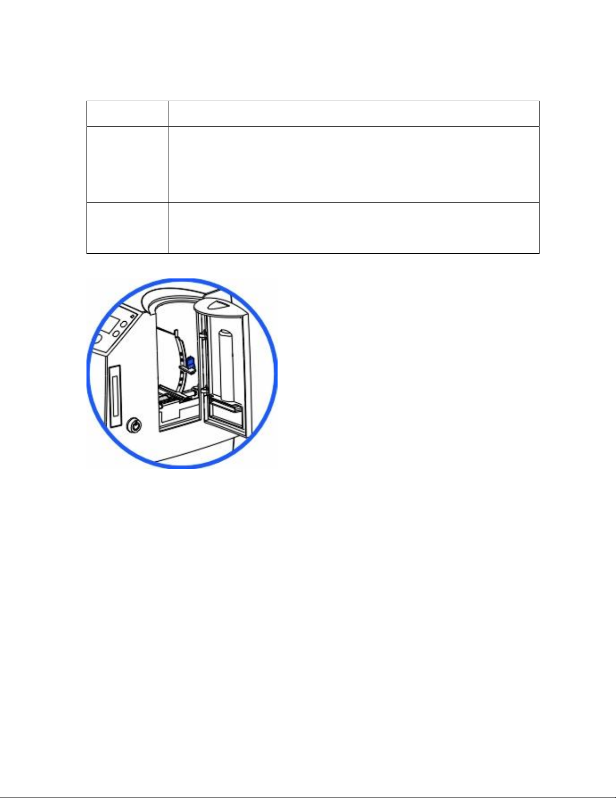
RESTRICTED USE ONLY Fargo Electronics, Inc.
Printer Components: Card Input and Output Hoppers
Type Description
Card Input
Hopper
Card Output
Hopper
The Card Input Hopper is where cards are initially loaded for printing, as
shown below. The Printer's hopper provides a large door that opens up
wide to make card loading simple and closes securely to help protect the
card stock. (Note: The Printer will hold a maximum of 100 cards in each
Card Input Hopper, based on a standard 30 mil. card thickness.)
All standard Card Printers provide a 100 card capacity Card Output
Hopper (based on a standard 30 mil card thickness). (Note: This hopper
stores the cards after they are printed.)
DTC500 Series Card Printer/Encoders User Guide (Rev. 6.0)
29
Page 48

RESTRICTED USE ONLY Fargo Electronics, Inc.
Printer Components: Lamination Roller
Danger: The Printer’s Lamination Roller can reach temperatures exceeded 350
degree F (175 C). Use extreme caution when operating the Laminator. Never touch the
Lamination Roller unless the Printer Power has been turned off for at least 20 to 30 minutes.
Type Description
Controls Both the Printer itself and the Printer’s software driver control the built-in
laminator.
Temperature
Adjustment
New
Temperature
Setting
To change the temperature of the laminator, adjust its temperature
through the Lamination tab within the Printer driver setup window.
Once adjusted, the new temperature settings will be sent down with the
next print job along with the rest of the Printer driver information.
Before printing begins, the laminator will automatically adjust itself to the
new temperature setting. (Note: This new temperature setting will
remain programmed within the Printer until it is once again changed
within the Printer driver or until the Printer is turned OFF.)
Whenever the Printer is turned OFF, the laminator will automatically reset
itself and return to its default temperature the next time the Printer is
turned ON.
Disconnect the Printer's power cord.
(Technician Note: Both the Power Switch and the Printer’s power cord
serve to reset the laminator to its default temperature. The temperature
setting within the Printer driver, however, will stay the same until it is
changed.)
DTC500 Series Card Printer/Encoders User Guide (Rev. 6.0)
30
Page 49

RESTRICTED USE ONLY Fargo Electronics, Inc.
Reviewing the Card Lamination Module
Danger: The Printer’s Lamination Roller can reach temperatures exceeding 350° F
(175° C). Use extreme caution when operating the Laminator. Never touch the Lamination
Roller unless the Printer has been turned off for at least 20 to 30 minutes.
Select Printer models support the attachment of an optional Card Lamination Module. This
module can be ordered pre-installed on your Printer from the factory or can be ordered
separately as a field upgradeable module.
DTC500 Series Card Printer/Encoders User Guide (Rev. 6.0)
31
Page 50

RESTRICTED USE ONLY Fargo Electronics, Inc.
Determining the Ready Status of the Card Lamination Module
Caution (Technician Note): Review these requirements:
If you are using a DTC525 Card Printer, you must have version 2.0.0-b2 or higher of the
Printer’s Main Firmware to use the Card Lamination Module.
If you do not have these versions, the Card Lamination Module will not function properly.
To check the version of your Printer’s Firmware, simply turn the Printer power OFF and
ON. (Note: The Firmware version will display momentarily on the Printer’s LCD display
during startup.)
If you are in need of a Firmware upgrade, please go to Fargo’s website (www.fargo.com)
for the latest Firmware file and updating instructions. (Note: This file must be updated
prior connecting the Card Lamination Module to the Printer.)
Technician Note: All DTC525 units manufactured after Serial Number A2350145 are
ready to have a Card Lamination Module attached to them.
DTC500 Series Card Printer/Encoders User Guide (Rev. 6.0)
32
Page 51

RESTRICTED USE ONLY Fargo Electronics, Inc.
Lamination
Lamination Station
Reviewing the Lamination Top Cover and Station
Component Description Cross Reference
Lamination
Top Cover
Lamination
Station
Lamination
LED Light
Opens to allow access to the Lamination
Station, overlaminate and card path.
Transfers overlaminates onto cards via its
heated lamination Roller. The Lamination
Station must be closed in order for the
Printer to begin laminating.
Securing
Latches
Cancel
See the Loading the
Overlaminate in Section 3,
page 115.
See the Loading the
Overlaminate in Section 3,
page 115.
Top Cover
Button
Resume
(pause) Button
Card Output
Hopper
Rejection
Card Hopper
DTC500 Series Card Printer/Encoders User Guide (Rev. 6.0)
33
Page 52

RESTRICTED USE ONLY Fargo Electronics, Inc.
Reviewing the Securing Latches and Lamination LED light
Component Description Cross Reference
Securing
Latches
Lamination
LED light
Locks the Lamination Station securely in
place when closed.
The Lamination LED light works in
conjunction with the Printer's LCD display to
help communicate the Printer's current
status. The following explains how to
interpret the LED light.
Off: Indicates the Printer and lamination
module power is OFF.
Solid Green light: Indicates the Card
Lamination Module is ready for
operation.
Slow Flashing Green light: Indicates
the lamination module's (pause) button
was pushed and that the lamination
module is paused. This also occurs
when the Lamination Station is open.
Fast Flashing Green light: Indicates
the lamination module is in need of
attention due to an error or an error
condition. Refer to the Printer's LCD
display for information.
See the Using the
Lamination tab (only with the
Card Lamination Module) in
Section 5, page 209.
See the Troubleshooting the
LCD Messages in Section 2,
page 46.
DTC500 Series Card Printer/Encoders User Guide (Rev. 6.0)
34
Page 53

RESTRICTED USE ONLY Fargo Electronics, Inc.
Reviewing the Cancel button
Component Description Cross Reference
Cancel
Button
The Cancel button serves to cancel the
current lamination job and reset the Card
Lamination Module for the next lamination
job.
If a card is left within the lamination
module after a print job is canceled, it will
automatically be ejected into the
Rejection Card Hopper. (Note: With the
Lamination Module's Transfer Station
open, this button can also be used to
manually rotate the Feed Rollers
forward. This is helpful when cleaning
the Rollers or if clearing jammed media.)
If you are printing and laminating
simultaneously and you would like to
cancel both the print and lamination jobs,
press the Printer's CANCEL softkey
button. (Note: This will cancel all jobs in
the Printer. Any card currently laminating
will finish and eject. The lamination
module's Cancel button cancels only the
lamination job.)
See the Section 3: Card
Lamination Module on
page 114.
Continued on the next page
DTC500 Series Card Printer/Encoders User Guide (Rev. 6.0)
35
Page 54

RESTRICTED USE ONLY Fargo Electronics, Inc.
Reviewing the Resume (pause) button
Component Description Cross Reference
Resume
(pause)
button
Press the Resume button to resume
operation after an error condition is
cleared.
If an error occurs, the lamination
module's LED will flash and the
Printer's LCD will report the specific
error.
If this happens, correct the error and
press the lamination module's
Resume button to continue printing.
Press this button to pause the
lamination module during normal
operation. (Note: The lamination
module will always finish its current task
before pausing.)
If this button is pressed while a card
is being laminated, the lamination
module will pause only after the
current card has finished laminating
and the lamination module has
reached a safe stopping point.)
See the Using the Lamination
tab (only with the Card
Lamination Module) in Section
5, page 209.
If the Printer is paused, the LED
light will flash slowly and will return
to solid when operation is resumed.
(Note: with the Lamination Station
open, the Resume button can also
be used to manually rotate the Feed
Rollers backward. This is helpful
when cleaning the Rollers or when
clearing jammed media.)
DTC500 Series Card Printer/Encoders User Guide (Rev. 6.0)
36
Page 55

RESTRICTED USE ONLY Fargo Electronics, Inc.
Reviewing the Rejection Card Hopper and Card Output Hopper
Component Description Cross Reference
Rejection
Card Hopper
Card Output
Hopper
The Rejection Card Hopper helps to
separate potentially bad cards from a stack
of good cards, which it eject into the Card
Output Hopper.
The Printer will automatically eject cards
into this hopper to indicate:
There is a printing error, laminating
error or encoding error.
There is a card is left in the Printer after
a print job is canceled or the Printer
restarted.
Stores up to 100 printed cards (30 mil
cards).
a. When the hopper has reached its
maximum capacity of cards, note that
the operation pauses and an Output
Hopper Full message appears on the
Printer's LCD display.
b. Remove the stack of cards from the
hopper.
See the Using the
Lamination tab (only with
the Card Lamination
Module) in Section 5, page
209.
See the Using the
Lamination tab (only with
the Card Lamination
Module) in Section 5, page
209.
c. Press the lamination module's Resume
button to continue. (Note: If printing
onto oversized cards, the Card Output
Hopper Door should be placed in the
open position in order for these larger
cards to eject properly.)
DTC500 Series Card Printer/Encoders User Guide (Rev. 6.0)
37
Page 56

RESTRICTED USE ONLY Fargo Electronics, Inc.
Reviewing the Module and Printer interaction
Term Description Cross Reference
Module
and
Printer
interaction
The Card Lamination Module works in
conjunction with the Printer to apply a
variety of different overlaminates to
printed cards, providing increased card
durability and security.
The Lamination Module features its own
LED indicator light and control buttons so
it can conveniently be operated separately
from the Printer. (Note: This means that
when printing a batch of cards, for
example, the Printer can be encoding and
printing one card while the lamination
module laminates another card for
maximum efficiency.)
In fact, you can even open the lamination
module to replace the overlaminate while
the Printer is printing or encoding and
vice versa.
See the Using the Lamination
tab (only with the Card
Lamination Module) in Section
5, page 209.
DTC500 Series Card Printer/Encoders User Guide (Rev. 6.0)
38
Page 57

RESTRICTED USE ONLY Fargo Electronics, Inc.
Reviewing the Module and LCD display interaction
Term Description Cross Reference
Module
and LCD
display
interaction
For ease of operation, the Card
Lamination Module works in tandem with
the Printer's LCD display to communicate
status message such as when an error
occurs or when it is time to replace the
overlaminate material.
If a lamination error does occur, the
Lamination Module's LED will flash and
an attention level message will appear on
the Printer's LCD display. (Note: Since it
is an ATTENTION level message, it will
not interrupt printing.)
a. Correct the error.
b. Press OK to clear the LCD's
ATTENTION message.
c. Press the Lamination Module's
Resume button to resume operation
or its Cancel button to cancel the
current lamination job and accept the
next. (Note: If canceled, the canceled
card will eject into the Rejection Card
Hopper.)
See the Using the Lamination
tab (only with the Card
Lamination Module) in Section
5, page 209.
Continued on the next page
DTC500 Series Card Printer/Encoders User Guide (Rev. 6.0)
39
Page 58

RESTRICTED USE ONLY Fargo Electronics, Inc.
Reviewing the Module’s Programmed Default Temperature
Term Description Reference
Programmed
Default
Temperature
Upon initial power up, the Lamination
Module is programmed to heat the
Lamination Roller up to its default
temperature.
Target Temperature: If a print job is
sent while the lamination module is
heating up, the Printer's LCD display
will read Laminator Warming. This will
alternate with LAM Temp: [current]
[target] which shows the current
temperature of the Lamination Roller
and the target temperature it is trying
to reach. (Note: This indicates that
the lamination Roller is heating to its
preset temperature.)
Initial Heating Process: The initial
heating process will generally take
about 3 to 4 minutes. (Note: The
LCD display will read Laminator
Warming or Laminator Cooling
whenever the Lamination Roller is
heating up or cooling down to the
prescribed temperature. When the
Lamination Module has reached its
target temperature, lamination will
begin.)
See the Using the Lamination
tab (only with the Card
Lamination Module) in Section
5, page 209.
DTC500 Series Card Printer/Encoders User Guide (Rev. 6.0)
40
Page 59

RESTRICTED USE ONLY Fargo Electronics, Inc.
Reviewing the Laminator Temperature Adjustment
Term Description
Laminator
Temperature
Adjustment
To change the temperature of the
Laminator, adjust its temperature through
the Lamination tab within the Printer
Driver setup window.
New Temperature Settings: Once
adjusted, the new temperature
settings will be sent down with the
next print job along with the rest of the
Printer driver information. Before
printing begins, the laminator will
automatically adjust itself to the new
temperature setting. (Note: This new
temperature setting will remain
programmed within the Printer until it
is once again changed within the
Printer driver or until the Printer is
turned OFF.)
Automatic Reset: Whenever the
Printer is turned OFF, the laminator
will automatically reset itself and
return to its default temperature the
next time the Printer is turned ON.
(Note: Pressing the lamination
module's or Printer's Cancel button or
switching the Printer power OFF and
ON both serve to reset the Laminator
to its default temperature.)
See the Using the Lamination
tab (only with the Card
Lamination Module) in Section
5, page 209.
Consistent Temperature: The
temperature setting within the Printer
driver stays the same until it is
changed.
DTC500 Series Card Printer/Encoders User Guide (Rev. 6.0)
41
Page 60

RESTRICTED USE ONLY Fargo Electronics, Inc.
Reviewing the Overlaminates
IMPORTANT! Fargo Card Printers require highly specialized overlaminates to function
properly. To maximize Printer life, reliability, printed card quality and durability, you must use
only Fargo Certified Supplies. For this reason, the Fargo warranty is void, where not
prohibited by law, if you use non-Fargo Certified Supplies. To order additional materials,
please contact the authorized reseller.
Reviewing the Thermal Transfer Film and PolyGuard Overlaminates
Term Description Cross Reference
Thermal
Transfer Film
and
PolyGuard
Overlaminates
The Card Lamination Module will accept
either a Thermal Transfer Film overlaminate
or a polyester patch overlaminate called
PolyGuard™.
Thermal Transfer Film: The Thermal
Transfer Film overlaminate is a relatively
thin material which covers a card edgeto-edge and provides a medium level of
card durability and security.)
PolyGuard overlaminate: PolyGuard
is a much thicker material which does
not cover edge-to-edge, but provides an
extremely high level of card durability
and security. (Note: PolyGuard is
available in either a 1.0 or .6 mil
thickness and should always be used for
those applications requiring the highest
degree of card durability and security.)
See the Loading the
Overlaminate procedure in
Section 3, page 115.
DTC500 Series Card Printer/Encoders User Guide (Rev. 6.0)
42
Page 61

RESTRICTED USE ONLY Fargo Electronics, Inc.
Reviewing the CR-90 or CR-100 Patch Size
Term Description Cross Reference
CR-90 or
CR-100
PolyGuard overlaminate is available in a
standard CR-80 patch size as well as a CR90 and CR-100 patch size for laminating
oversized CR-90 or CR-100 cards. (Note:
Thermal Transfer Film overlaminate will
accommodate CR-80 and CR-90 card sizes,
but is not recommended for CR-100 cards.)
See the Loading the
Overlaminate procedure in
Section 3, page 115.
Reviewing the Overlaminate Design
Term Description Cross Reference
Design Both PolyGuard and the Thermal Transfer
Film overlaminates are available in either a
clear or generic secure holographic-type
design. (Note: Custom holographic-type
overlaminates are also available with specific
designs, patterns, logos and security
features.)
Please contact the authorized reseller for
more information about custom
Overlaminates.
See the Loading the
Overlaminate procedure in
Section 3, page 115.
DTC500 Series Card Printer/Encoders User Guide (Rev. 6.0)
43
Page 62

RESTRICTED USE ONLY Fargo Electronics, Inc.
Reviewing the Visual Security Solutions
VeriMarkTM Cards - 2-D holographic foil application
VeriMarkTM Cards are a low cost, customized 2-D holographic foil application, that is made
in two steps.
The first step is to emboss a base foil 1.9 cm (L) x 1.3 cm (H) onto the surface of a blank
white card.
The second step is debossing a custom made dye into the surface of the base foil -
leaving a customized image, logo or text provided by the customer.
Two separate color foils are used to contrast the impression.
End Users will be able to choose between 8 different card placements (4 - landscape) and
(4-portrait) where the VeriMarkTM can be located. When its time to print through the driver,
the End User will select the location on their organizations card design around which no
printing and overlay will be placed.
Custom HoloMarkTM Cards
A Custom HoloMark TM Card is a three-dimensional holographic image transferred to metal
foil and embossed to blank cards. The image is customer specific and the program mirrors
our holographic laminates program with a couple exceptions.
Visual Security - Card Stock Part Numbers
All Visual Security Cards will be offered on the following Fargo Card Stocks only:
P/N# 81754 Ultra Card
P/N# 81762 Ultra Card III with hi-coercivity magnetic stripe
P/N# 81763 Ultra Card III
Visual Security - Fargo Certified Overlaminates (Special Order in 50
quantity minimum)
Part No. 82255: PolyGuard 1.0 mil for HoloMarkTM and VeriMarkTM Cards, Clear
Part No. 82256: PolyGuard 1.0 mil for HoloMarkTM and VeriMarkTM Cards, High
Resolution Globe design hologram with "Secure" micro-text
DTC500 Series Card Printer/Encoders User Guide (Rev. 6.0)
44
Page 63

RESTRICTED USE ONLY Fargo Electronics, Inc.
Visual Security Card Stock - Tolerances
Tolerance of base foil placement will equal +/- .010" from the nearest edges of the card
Tolerance of layered foil will equal +/- .010"
VeriMarkTM - Application Specifications
VeriMarkTM foils will cover a dimensional area of 1.9 cm length x 1.3 cm height. The
exclusive areas are as follows:
VeriMarkTM Card customers will be able to choose 1 of 8 pre-defined placements
(corners) via printer driver (4 positions) Landscape and (4 Positions) Portrait mode.
VeriMarkTM foil placement will not interfere with card punch slots .
Foil color base is silver; debossed impression is gold foil.
VeriMarkTM foil placement will be located 0.4 cm from the edges of the card except for
the top two locations on portrait orientation cards (positions E & F). The foil will be
located 0.9 cm from the top of the card and 0.4 cm from the sides of the card.
HoloMarkTM and Custom HoloMarkTM - Application Specifications
HoloMarkTM and Custom HoloMarkTM foils will cover a dimensional area of 1.5 cm x 1.5
cm. The exclusive areas are as follows:
HoloMarkTM and Custom HoloMarkTM card end-users will be able to choose 1 of 8 pre-
defined placements (corners) via printer driver (4 positions) Landscape and (4 positions)
Portrait mode.
HoloMarkTM foil placement will not interfere with card punch slots.
Foil Color options will be silver or gold.
Outside edge placement of Foil impression options on card will be 0.4 cm from edge of
card.
HoloMarkTM foil placement options will be at all four corners of card located 0.4 cm from
edge of card.
DTC500 Series Card Printer/Encoders User Guide (Rev. 6.0)
45
Page 64

RESTRICTED USE ONLY Fargo Electronics, Inc.
Section 2: General Troubleshooting
IMPORTANT! Fargo Card Printers require highly specialized print Ribbons to function
properly. To maximize Printer life, reliability, printed card quality and durability, you must use
only Fargo Certified Supplies. For this reason, your Fargo warranty is void, where not
prohibited by law, if you use non-Fargo Certified Supplies. To order additional materials,
please contact your authorized reseller.
Reviewing the LCD display and LED light
The LCD display provides the current status of the Printer. Refer to the following tables for a
complete list and cause of all possible LCD messages. The tables (in this section) display the
LCD messages. If the LCD message is communicating an error or requires an action, these
tables will also offer a solution to what should be done.
The purpose of this section is to provide the User with specific procedures relating to the
LCD/SmartGuard Messages, Communication Errors, Card Feeding Errors, Encoding Errors,
Printing Process Errors and Diagnosing the Image Problems for the DTC500 series card
Printer.
Troubleshooting the LCD Messages
Message Cause Solution
Aligning Ribbon If this appears as a prompt, it
indicates the print Ribbon is
self-aligning to the proper
position for printing.
If this appears as an
ERROR, it indicates the print
Ribbon is not installed
properly or is damaged.
Card Hopper
Empty
Card Hopper Jam Indicates that the Card
Indicates the Printer has run
out of blank cards.
Hopper is unable to move
from one hopper to the next.
See Resolving the Ribbon Alignment
Error Message in Section 2, page 82.
See the Resolving the Card Hopper
Empty Error Message procedure in
Section 2, page 73.
Clear any obstructions and close the
hopper door.
See Resolving the Card Hopper Jam
Error Message in Section 2, page 72.
Continued on the next page
DTC500 Series Card Printer/Encoders User Guide (Rev. 6.0)
46
Page 65

RESTRICTED USE ONLY Fargo Electronics, Inc.
ation or
Troubleshooting the LCD Messages (continued)
Message Cause Solution
Card Jam Indicates that a card is
jammed in the Print St
card flipping area of the
Printer.
Card Jam: Flipper Indicates that a card is
jammed in the card flipping
area of the Printer.
Card Jam: Print Indicates that a card is
jammed in the Print Station
of the Printer.
Card Jam: Mag Indicates that a card is
jammed in the magnetic
encoding area of the Printer.
Card Jam: Smart Indicates that a card is
jammed in the Smart Card
encoding area of the Printer.
Data Input Indicates that the print data
sent to the Printer is corrupt
or has been interrupted.
See Card Feeding Errors in Section 2,
page 67.
See Resolving cards jamming on the
Flipper table in Section 2, page 70.
See Card Feeding Errors in Section 2,
page 67.
See Removing the Card jam in the
Printer’s Magnetic Encoding Area in
Section 2, page 77.
See Removing the Card jam in the
Printer’s Smart Card Encoding Area in
Section 2, page 78.
See Resolving the Communication
Errors in Section 2, page 62.
Data Timeout Indicates that the print data
sent to the Printer is corrupt
or has been interrupted.
DRAM Memory
Error
Indicates that the Printer's
Memory Module is bad or is
not installed properly.
See Resolving the Communication
Errors in Section 2, page 62.
See Resolving the DRAM Memory
Error in Section 7, page 231.
Continued on the next page
DTC500 Series Card Printer/Encoders User Guide (Rev. 6.0)
47
Page 66

RESTRICTED USE ONLY Fargo Electronics, Inc.
Troubleshooting the LCD Messages (continued)
Message Cause Solution
EE Checksum
Error
Indicates that the permanent
circuit board memory is bad.
EE Memory Error Indicates that the permanent
circuit board memory is bad.
Ejecting Used
Card
Indicates that the system
Firmware has detected a
card already in the Printer.
Failed To
Initialize
Indicates that an unexpected
hardware error has occurred.
Flipper Alignment Indicates that the Printer is
unable to align the Flipper
table.
FPGA Indicates that an unexpected
hardware error has occurred.
FPGA Load Fail Indicates that an unexpected
hardware error has occurred.
See Resolving the EE Checksum
Error in Section 8, page 230.
See Resolving the EE Memory Error
in Section 8, page 230.
This card has been ejected; however,
it may contain encoded data and
should be disposed of in a proper
manner.
See Board Errors in Section 8, page
230.
See Resolving the Flipper Alignment
Error Message in Section 2, page 89.
See Resolving the FPGA Error in
Section 8, page 231.
See Resolving the FPGA Error in
Section 8, page 231.
FPGA Timeout Indicates that an unexpected
hardware error has occurred.
Head Lift Indicates that the Printer was
unable to raise or lower the
Printhead.
See Resolving the FPGA Error in
Section 8, page 231.
See Resolving the Headlift Error
Message in Section 2, page 86.
Continued on the next page
DTC500 Series Card Printer/Encoders User Guide (Rev. 6.0)
48
Page 67

RESTRICTED USE ONLY Fargo Electronics, Inc.
Troubleshooting the LCD Messages (continued)
Message Cause Solution
Head Resistance
Error
The LCD requires that a
value be input for the Print
Head Resistance.
Head Voltage
Error
A hardware fault has
prevented a correct setting
of the Printhead voltage.
Hopper 1 Empty Card Hopper 1 has run out
of cards. (Note: The Printer
will continue printing from
Hopper 2 if First Available is
set as the Card Hopper
Selection in the Driver.)
Hopper 2 Empty Card Hopper 2 has run out
of cards. (Note: The Printer
will continue printing from
Hopper 1 if First Available is
set as the Card Hopper
Selection in the Driver.)
Enter a value for head resistance in
the LCD's Printer Setup menu.
See Setting the Printhead Resistance
in Section 8, page 246.
A default value will be used.
See the Resolving the Card Hopper
Empty Error Message procedure in
Section 2, page 73.
See the Resolving the Card Hopper
Empty Error Message procedure in
Section 2, page 73.
Invalid Flip
Command
Invalid Print
Ribbon
Indicates that the Printer
received a command to print
both sides of the card, but
this model does not support
dual-sided printing.
Indicates an unauthorized
Ribbon.
Press CANCEL to reset the Printer or
RESUME to print onto two separate
cards.
Install a valid, Fargo-authorized
Ribbon and press RESUME to
continue.
See Resolving the Unknown Ribbon
Type Error Message in Section 2,
page 85.
Continued on the next page
DTC500 Series Card Printer/Encoders User Guide (Rev. 6.0)
49
Page 68

RESTRICTED USE ONLY Fargo Electronics, Inc.
Troubleshooting the LCD Messages (continued)
Message Cause Solution
Mag Encode
Failed
Indicates that the card's
Magnetic Stripe was not
encoded properly.
Multiple Cards
Fed
Indicates that two or more
cards were fed from the
Card Hopper.
No ENC
Response
Indicates that there is no
response from the Encoder
control module.
No MAG Encoder Indicates that the Printer has
received encoding data, but
the Printer is not configured
with this Encoder type.
No Ribbon
Installed
Indicates that the Printer is
trying to print with no print
Ribbon installed.
No Smart
Encoder
Indicates that the Printer has
received encoding data, but
the Printer is not configured
with this Encoder type.
See Resolving the Failed Magnetic
Encode Error Message in Section 2,
page 76.
See Resolving the Card Feeding
Errors in Section 2, page 67.
See Resolving the No ENC Response
Error Message in Section 2, page 74.
See Resolving the No Magnetic
Encoder Error Message in Section 2,
page 74.
Install the proper print Ribbon and
press RESUME to continue or
CANCEL to reset the Printer.
See Resolving the No Smart Encoder
Error Message in Section 2, page 76.
Pause... Indicates the Printer is
paused.
Press the Printer's RESUME button to
continue or CANCEL to clear all
pending print jobs and reset the
Printer.
Please Clean
Printer
This message appears every
3,000 prints to remind you to
See the Cleaning the Printer
procedure in Section 4, page 209.
perform the recommended
Printer maintenance.
Please Remove
Card
Indicates that the card is
jammed in the Print Station
See Card Feeding Errors in Section 2,
page 67.
or card flipping area of the
Printer.
DTC500 Series Card Printer/Encoders User Guide (Rev. 6.0)
Continued on the next page
50
Page 69

RESTRICTED USE ONLY Fargo Electronics, Inc.
Troubleshooting the LCD Messages (continued)
Message Cause Solution
Print Data Indicates that the print data
sent to the Printer is corrupt
or has been interrupted.
Print Ribbon Low Indicates that the print
Ribbon will soon run out.
Print Ribbon Out Indicates that the print
Ribbon has run out.
Print Station
Open
Indicates that the Print
Station is open during
printing.
Print Timeout Indicates that the Printer was
unable to complete the print
process.
Printhead Temp Indicates that the Printhead
Temperature Regulator is
not functioning properly.
See Communications Errors in
Section 2, page 53.
If printing a large number of cards,
replace the Ribbon now or monitor the
Printer until the Ribbon is gone and
install a new Ribbon.
Install a new Ribbon and press
RESUME to continue.
Close the Station and press the
Printer's RESUME button to continue
or CANCEL to reset the Printer.
See Communications Errors in
Section 2, page 53.
See Resolving the Printhead Temp
Error Message in Section 2, page 88.
Program
Exception
RAM Memory
Error
Ribbon
Jam/Broken
Indicates that the system
Firmware has detected an
error while attempting to
process the current print job.
Indicates that the Printer's
Memory Module is bad or
not installed properly.
The print Ribbon is either
jammed or broken.
See the Updating the Printer’s
Firmware procedure in Section 8,
page 259.
See Resolving the DRAM Memory
Error in Section 7, page 231.
See Resolving the Ribbon Jam/Broke
Error Message in Section 2, page 83.
Continued on the next page
DTC500 Series Card Printer/Encoders User Guide (Rev. 6.0)
51
Page 70

RESTRICTED USE ONLY Fargo Electronics, Inc.
Troubleshooting the LCD Messages (continued)
Message Cause Solution
Smart Encode
Failed
The card's smart chip was
not encoded properly.
Starting Self-test The self-test print is
preparing to print.
Testing Memory The Printer's memory is
being tested.
Top Cover Open A print job was started with
the Top Cover open.
Unable To Feed
Card
The Printer is unable to feed
a card from the Card
Hopper.
Unknown Ribbon
Type
The Printer does not
recognize the Ribbon
installed.
Update Failed The Firmware update was
interrupted or not completed
successfully.
See Resolving the Failed Smart
Encode Error Message in Section 2,
page 76.
See the Printing the Self-test
procedure in Section 7, page 238.
Upon completion, the Printer will
continue its normal boot up sequence.
Close the Printer and press RESUME
to continue or CANCEL to reset the
Printer.
See Resolving the Card Feeding
Errors in Section 2, page 67.
See Resolving the Unknown Ribbon
Type Error Message in Section 2,
page 85.
See Resolving an Upgrade Failed
error in Section 2, page 90.
Update Firmware
Now
An error has occurred in
trying to load the Firmware.
The system Firmware MUST be
updated.
See Updating the Printer's Firmware
in Section 9, page 259.
Wrong Print
Ribbon
The print Ribbon installed in
the Printer does not match
the Ribbon type selected in
See Resolving the Wrong Print
Ribbon Error Message in Section 2,
page 84.
the Printer driver.
DTC500 Series Card Printer/Encoders User Guide (Rev. 6.0)
52
Page 71

RESTRICTED USE ONLY Fargo Electronics, Inc.
Verifying the Encoding Settings for DTC500 Series Card Printer and
Encoders
The purpose of this Technical Update is to clarify Encoding Settings in the DTC500 Series
Card Printer/Encoders. To ensure the proper function of your DTC500 Series Printer, all of
the Printer’s Encoding Options must be set correctly in the Printer’s LCD display. Please
refer to the tables (on the next page) to review the proper settings for (a) the different
DTC500 Series Printer models and (b) the different symptoms related to incorrect settings.
Follow these instructions to access your DTC500 Series Printer displays:
Use the Printers LCD display touch pad to press the Menu button.
Use the down arrow button to scroll down and select Setup Printer.
Use the down arrow button to scroll down and select the Encoder Settings.
The three (3) Encoding Options available are Mag, Smart and Prox. These options must be
set up according to the Printer model to avoid printing issues.
If you are unsure what your Printer should be set to at this time, please see the tables on
the following pages.
You can compare your Printer’s part number (located on the silver label on the bottom of
your Printer) to the part number (shown in the tables on the following pages) in order to
find the Printers correct settings.
DTC500 Series Card Printer/Encoders User Guide (Rev. 6.0)
53
Page 72

RESTRICTED USE ONLY Fargo Electronics, Inc.
Verifying Encoder Settings for DTC 510/DTC 515 (Symptom A)
Symptoms of incorrect settings (Symptom A): Printer will try to rotate the Flipper Table
during a print job. The Flipper (however) is not powered and the printer will stall out with a
Flipper Jam or Data Time Out error.Table 1 (DTC 510 and DTC 515), Technical Update No.
66 (dated 09/24/2003)
Printer Model Part No. Proper Encoder Display
Settings
DTC 510 No Encoding
DTC 515 No Encoding
85301
85351
Mag None
Smart None
Prox None
Verifying Encoder Settings for DTC 510/DTC 515 (Symptom B)
Symptom of incorrect settings (Symptom B): Flipper Table will freely rotate and cause
card jams at the Flipper Table.
Printer Model Part No. Proper Encoder Display
Settings
DTC 510 Magnetic encoding
DTC 515 Magnetic encoding
DTC 510 Docking Station
DTC 515 Docking Station
85302
85352
85303
85353
Mag Installed
Smart None
Prox None
Mag None
Smart Installed
Prox None
DTC 510 Docking Station + Magnetic
Encoding
DTC 515 Docking Station + Magnetic
Encoding
DTC500 Series Card Printer/Encoders User Guide (Rev. 6.0)
85304
85354
Mag Installed
Smart Installed
Prox None
Continued on the next page
54
Page 73

RESTRICTED USE ONLY Fargo Electronics, Inc.
Verifying Encoder Settings for DTC 510/DTC 515 (Symptom B) (continued)
Printer Model Part No. Proper Encoder Display
Settings
DTC 510 JIS II Magnetic Encoder
DTC 515 JIS II Magnetic Encoder
DTC 510 Docking Station + Magnetic
Encoder
DTC 515 Docking Station + Magnetic
Encoder
DTC 510 Docking Station, Contact
Smart Card Encoder
DTC 515 Docking Station, Contact
Smart Card Encoder
DTC 510 Docking Station, MIFARE
Contactless Smart Card Encoder
85305
85355
85306
85356
91101
91201
91102
Mag Installed
Smart None
Prox None
Mag Installed
Smart Installed
Prox None
Mag None
Smart Installed
Prox None
Mag None
Smart Installed
DTC 515 Docking Station, MIFARE
Contactless Smart Card Encoder
DTC 510 Docking Station, HID Prox
Reader
DTC 515 Docking Station, HID Prox
Reader
DTC 510 Docking Station, Contact
Smart Card encoder MIFARE Encoder
DTC 510 Docking Station, Contact
Smart Card encoder MIFARE Encoder
91202
91104
91204
91105
91205
Prox None
Mag None
Smart Installed
Prox Installed
Mag None
Smart Installed
Prox None
Continued on the next page
DTC500 Series Card Printer/Encoders User Guide (Rev. 6.0)
55
Page 74

RESTRICTED USE ONLY Fargo Electronics, Inc.
Verifying Encoder Settings for DTC 510/DTC 515 (Symptom B) (continued)
Printer Model Part No. Proper Encoder Display
Settings
DTC 510 Docking Station, MIFARE
Encoder, HID Prox Encoder
DTC 515 Docking Station, MIFARE
Encoder, HID Prox Encoder
DTC 510 Docking Station, Contact
Smart Card Encoder, MIFARE Encoder,
HID Prox Reader
DTC 515 Docking Station, Contact
Smart Card Encoder, MIFARE Encoder,
HID Prox Reader
DTC 510 Docking Station, Magnetic
Encoder, Contact Smart Card encoder
DTC 515 Docking Station, Magnetic
Encoder, Contact Smart Card encoder
DTC 510 Docking Station, Magnetic
Encoder, MIFARE Encoder
91106
91206
91107
91207
91108
91208
91109
Mag None
Smart Installed
Prox Installed
Mag None
Smart Installed
Prox Installed
Mag Installed
Smart Installed
Prox None
Mag Installed
Smart Installed
DTC 515 Docking Station, Magnetic
91209
Encoder, MIFARE Encoder
DTC 510 Docking Station, Magnetic
Encoder, HID Prox Reader
91110
DTC 515 Docking Station, Magnetic
91210
Encoder, HID Prox Reader
DTC500 Series Card Printer/Encoders User Guide (Rev. 6.0)
Prox None
Mag Installed
Smart Installed
Prox Installed
Continued on the next page
56
Page 75

RESTRICTED USE ONLY Fargo Electronics, Inc.
Verifying Encoder Settings for DTC 510/DTC 515 (Symptom B) (continued)
Printer Model Part No. Proper Encoder Display
Settings
DTC 510 Docking Station, Magnetic
Encoder, Contact Smart Card Encoder,
MIFARE Encoder
DTC 515 Docking Station, Magnetic
Encoder, Contact Smart Card encoder
DTC 510 Docking Station, Magnetic
Encoder, Contact Smart Card Encoder,
HID Prox Reader
DTC 515 Docking Station, Magnetic
Encoder, Contact Smart Card Encoder,
HID Prox Reader
DTC 510 Docking Station, Magnetic
Encoder, MIFARE Encoder, HID Prox
Reader
DTC 515 Docking Station, Magnetic
Encoder, MIFARE Encoder, HID Prox
Reader
91111
91211
91112
91212
91113
91213
Mag Installed
Smart Installed
Prox None
Mag Installed
Smart Installed
Prox Installed
Mag Installed
Smart Installed
Prox Installed
DTC 515 Docking Station, Magnetic
91114
Encoder, Contact Smart Card Encoder,
MIFARE Encoder, HID Prox Reader
DTC 515 Docking Station, Magnetic
91214
Encoder, Contact Smart Card Encoder,
MIFARE Encoder, HID Prox Reader
DTC500 Series Card Printer/Encoders User Guide (Rev. 6.0)
Mag Installed
Smart Installed
Prox Installed
57
Page 76

RESTRICTED USE ONLY Fargo Electronics, Inc.
Verifying the Encoding Settings for the DTC 520/DTC 525
Symptoms of incorrect settings: Printers card feed motor for the flipper table will rotate
backwards and then produce a Card Jam error.
Printer Model Part No. Proper Encoder Display
Settings
DTC 520 No Encoding
DTC 525 No Encoding
DTC 520 Magnetic encoding
DTC 525 Magnetic encoding
DTC 520 Docking Station
DTC 525 Docking Station
DTC 520 Docking Station + Magnetic
Encoding
DTC 525 Docking Station + Magnetic
Encoding
85401
85451
85402
85452
85403
85453
85404
85454
Mag None
Smart None
Prox None
Mag Installed
Smart None
Prox None
Mag None
Smart Installed
Prox None
Mag Installed
Smart Installed
Prox None
DTC 520 JIS II Magnetic Encoder
DTC 525 JIS II Magnetic Encoder
85405
85455
Mag Installed
Smart None
Prox None
Continued on the next page
DTC500 Series Card Printer/Encoders User Guide (Rev. 6.0)
58
Page 77

RESTRICTED USE ONLY Fargo Electronics, Inc.
Verifying the Encoding Settings for the DTC 520/DTC 525 (continued)
Printer Model Part No. Proper Encoder Display
Settings
DTC 520 Docking Station + Magnetic
Encoder
DTC 525 Docking Station + Magnetic
Encoder
DTC 520 Docking Station, Contact
Smart Card Encoder
DTC 525 Docking Station, Contact
Smart Card Encoder
DTC 520 Docking Station, MIFARE
Contactless Smart Card Encoder
DTC 525 Docking Station, MIFARE
Contactless Smart Card Encoder
DTC 520 Docking Station, HID Prox
Reader
DTC 525 Docking Station, HID Prox
Reader
85406
85456
91301
91401
91302
91402
91304
91404
Mag Installed
Smart Installed
Prox None
Mag None
Smart Installed
Prox None
Mag None
Smart Installed
Prox None
Mag None
Smart Installed
Prox Installed
DTC 520 Docking Station, Contact
Smart Card encoder MIFARE Encoder
DTC 525 Docking Station, Contact
Smart Card encoder MIFARE Encoder
91305
91405
Mag None
Smart Installed
Prox None
Continued on the next page
DTC500 Series Card Printer/Encoders User Guide (Rev. 6.0)
59
Page 78

RESTRICTED USE ONLY Fargo Electronics, Inc.
Verifying the Encoding Settings for the DTC 520/DTC 525 (continued)
Printer Model Part No. Proper Encoder Display
Settings
DTC 520 Docking Station, MIFARE
Encoder, HID Prox Encoder
DTC 555 Docking Station, MIFARE
Encoder, HID Prox Encoder
DTC 520 Docking Station, Contact
Smart Card Encoder, MIFARE Encoder,
HID Prox Reader
DTC 525 Docking Station, Contact
Smart Card Encoder, MIFARE Encoder,
HID Prox Reader
DTC 520 Docking Station, Magnetic
Encoder, Contact Smart Card encoder
DTC 525 Docking Station, Magnetic
Encoder, Contact Smart Card encoder
DTC 520 Docking Station, Magnetic
Encoder, MIFARE Encoder
DTC 525 Docking Station, Magnetic
Encoder, MIFARE Encoder
91306
91406
91307
91407
91308
91408
91309
91409
Mag None
Smart Installed
Prox Installed
Mag None
Smart Installed
Prox Installed
Mag Installed
Smart Installed
Prox None
Mag Installed
Smart Installed
Prox None
DTC 520 Docking Station, Magnetic
Encoder, HID Prox Reader
DTC 525 Docking Station, Magnetic
Encoder, HID Prox Reader
91310
91410
Mag Installed
Smart Installed
Prox Installed
Continued on the next page
DTC500 Series Card Printer/Encoders User Guide (Rev. 6.0)
60
Page 79

RESTRICTED USE ONLY Fargo Electronics, Inc.
Verifying the Encoding Settings for the DTC 520/DTC 525 (continued)
Printer Model Part No. Proper Encoder Display
Settings
DTC 520 Docking Station, Magnetic
Encoder, Contact Smart Card Encoder,
MIFARE Encoder
DTC 525 Docking Station, Magnetic
Encoder, Contact Smart Card encoder
DTC 520 Docking Station, Magnetic
Encoder, Contact Smart Card Encoder,
HID Prox Reader
DTC 525 Docking Station, Magnetic
Encoder, Contact Smart Card Encoder,
HID Prox Reader
DTC 520 Docking Station, Magnetic
Encoder, MIFARE Encoder, HID Prox
Reader
DTC 525 Docking Station, Magnetic
Encoder, MIFARE Encoder, HID Prox
Reader
91311
91411
91312
91412
91313
91413
Mag Installed
Smart Installed
Prox None
Mag Installed
Smart Installed
Prox Installed
Mag Installed
Smart Installed
Prox Installed
DTC 525 Docking Station, Magnetic
Encoder, Contact Smart Card Encoder,
MIFARE Encoder, HID Prox Reader
DTC 525 Docking Station, Magnetic
Encoder, Contact Smart Card Encoder,
91314
91414
MIFARE Encoder, HID Prox Reader
DTC500 Series Card Printer/Encoders User Guide (Rev. 6.0)
Mag Installed
Smart Installed
Prox Installed
61
Page 80

RESTRICTED USE ONLY Fargo Electronics, Inc.
Communications Errors
Resolving the Communication Errors
Symptom(s): Incorrect output, communications error on PC or Printer, stalling, no response
from Printer, no job printed, “Paper out” error.
Step Procedure
1 Confirm that the system meets the minimum requirements, as shown here:
IBM-PC or compatible
Windows 95/98/ME/NT/2000/XP Pentium™ class 133 MHz computer with
32 MB of RAM or higher
200 MB free hard disk space or higher
ECP Parallel Port with DMA access
2 Confirm the correct installation of the Printer driver.
a. Close the software program and check the Printer driver.
b. Reboot the computer.
c. Be sure the correct setup options within the Printer driver are selected.
d. Confirm that the driver is current by checking at: www.fargo.com
3 Verify the use of an adequate data cable.
a. Use a double-shielded parallel cable (no longer than six feet in length).
(Note: Data transmission failure can be attributed to a long or faulty
parallel cable.)
b. Use an I-EEE 1284 compliant cable to reduce the effect of radio emissions
from computers, monitors and other equipment that can broadcast Radio
frequency interference (RFI).
Continued on the next page
DTC500 Series Card Printer/Encoders User Guide (Rev. 6.0)
62
Page 81

RESTRICTED USE ONLY Fargo Electronics, Inc.
Resolving the Communication Errors (continued)
Step Procedure
4 Determine if there is interference from an external device.
a. Do not use an A/B Switch Box or other peripheral in line with the parallel
cable.
b. If using a Switch Box or other peripheral, remove it while testing
communication between the computer and the Printer.
c. If needed, replace the Switch Box or other peripheral (once it is determined
that the cause of the interference is not the Switch Box or the peripheral).
d. Alternative: Add a second Parallel Port into the computer (if a second
Printer is required).
Continued on the next page
DTC500 Series Card Printer/Encoders User Guide (Rev. 6.0)
63
Page 82

RESTRICTED USE ONLY Fargo Electronics, Inc.
Resolving the Communication Errors (continued)
Step Procedure
5 Determine the nature of the problem with printing from the application.
a. Print a self-test from the Printer to ensure that the Printer (itself) is
functioning properly. See the Printing the Self-test in Section 8, page 238.
b. Print the Windows test page that is located in the General tab of the driver.
c. Use WordPad (a Windows 95/ 98/ ME/ NT/ 2000/XP word processing
program in the Accessories Program Group) via Start > Programs >
Accessories > WordPad. Follow this procedure:
Open the program and type: “This is a Test.”
Select File > Page Setup and click on the Printer button.
Ensure that the DTC500 Series Card Printer is selected and click OK.
Change all the margin settings to zero (0) and click OK.
Select File > Print on the Menu Bar.
Go to File on Menu Bar and select Print.
Continued on the next page
DTC500 Series Card Printer/Encoders User Guide (Rev. 6.0)
64
Page 83

RESTRICTED USE ONLY Fargo Electronics, Inc.
Resolving the Communication Errors (continued)
Step Procedure
6 Determine if the Parallel Port mode is set correctly.
a. Ensure that the Parallel Port is set to the Enhanced Communication Port
(ECP) mode. (Note: The port mode can be determined by checking the
Device Manager tab in the System Control Panel.)
b. If the port mode is not set to ECP, it will need to be changed in the
computers BIOS. (Note: Refer to the appropriate computer manual for
instructions on how to change the Parallel Port mode.)
Continued on the next page
DTC500 Series Card Printer/Encoders User Guide (Rev. 6.0)
65
Page 84

RESTRICTED USE ONLY Fargo Electronics, Inc.
Resolving the Communication Errors (continued)
Step Procedure
7 Determine whether there is an adequate or inadequate hard drive space.
Caution: A large volume of temporary files on the computer can
cause communications errors.
Access the temporary files by following this process:
Search for all folders called TEMP. Once found, clear out the contents of
the folders.
Run the System Tool - Disk Defragmenter (found in the Accessories folder
of the Start Menu) if using Windows 95/98/ME/2000/XP,.
Use a disk cleanup utility (such as Disk Cleanup found in the System
Tools folder of the Start menu) or use a third party application.
DTC500 Series Card Printer/Encoders User Guide (Rev. 6.0)
66
Page 85

RESTRICTED USE ONLY Fargo Electronics, Inc.
Card Feeding Errors
Resolving the Card Feeding Errors
Symptom: Two or more cards feed at the same time or the cards will not feed at all.
Step Procedure
1 Clean the Input Roller.
a. Open the Printer's top covers and remove all cards and print Ribbons from
the Printer.
b. Leave the Printer power ON and the top covers open throughout this
procedure. (Note: The card-cleaning cartridge can also remain within the
Printer during this cleaning process.)
c. Use a cleaning card from the Printer Cleaning Kit and remove its adhesive
backing paper.
d. Insert the cleaning card into the Exception Card Slot until the card stops.
Verify that the longest non-adhesive end of the cleaning card enters the
Printer first and that the sticky side is facing DOWNWARD
e. Press the FORWARD button several times to feed the Cleaning Card all
the way through the Printer.
Continued on the next page
DTC500 Series Card Printer/Encoders User Guide (Rev. 6.0)
67
Page 86
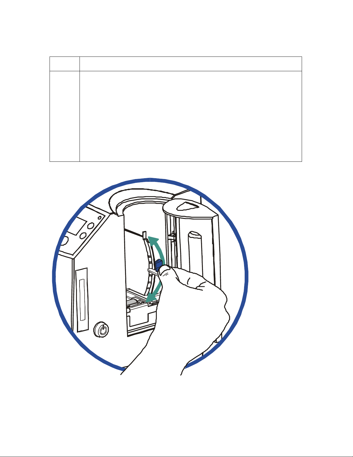
RESTRICTED USE ONLY Fargo Electronics, Inc.
Resolving the Card Feeding Errors (continued)
Step Procedure
2 Ensure the Card Thickness Lever is set correctly, as shown below.
a. Press the Card Thickness Lever Lock and then push the Card Thickness
Lever up or down to the appropriate setting.
b. with any of the Card Thickness settings, move the slide slightly toward a
higher setting until the cards begin feeding (if the Printer seems unable to
feed cards at the selected setting).
c. Move the slide slightly toward a lower setting (if the Printer seems to
double-feed cards). (Note: The card thickness slide is adjustable to
accommodate card thickness variations that often occur even within
standard card sizes.)
DTC500 Series Card Printer/Encoders User Guide (Rev. 6.0)
68
Page 87

RESTRICTED USE ONLY Fargo Electronics, Inc.
Insert cards neatly stacked.
Card Feed Roller
Resolving the Card Feeding Errors (continued)
Step Procedure
3
4 Ensure that the cards are loaded properly in the Input Hopper.
5 Verify that the Hopper Lift (A000124) is operational.
a. Check for static build up between cards. (Note: Occasionally, a static
charge will build up between the surfaces of two or more cards causing
them to stick together.)
b. Reduce or eliminate this static charge by separating the cards manually
before placing them in the input hopper.
a. Load the cards into the Printer by inserting them straight into the hopper
and setting them on the feed Roller.
a. Reset Power to the Printer.
b. Open the Card Hopper Door and watch to verify that the Hopper Cycles
on startup.
c. If the Hopper does not cycle on startup, remove the top cover and verify
that the Hopper Lift Motor is plugged in properly.
d. If the Hopper Lift Motor is plugged in, disconnect it and attach a 9-volt
battery to the leads.
e. If the Motor turns, replace the Main Board (as needed). See the
Replacing the Main Board procedure in Section 5, page Error!
Bookmark not defined..
Card Hopper
(side view)
Cards
DTC500 Series Card Printer/Encoders User Guide (Rev. 6.0)
69
Page 88
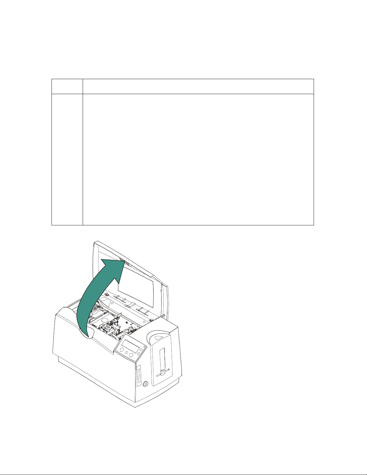
RESTRICTED USE ONLY Fargo Electronics, Inc.
Resolving the Card Jam on the Flipper Table
Symptom: Cards are jamming on or at the Flipper Table or a Card Jam: Flip error is
displayed on the LCD.
Step Procedure
1 Verify that the Card Feed Roller on the Flipper table is not running
backwards. (Note: Having an Encoder installed in the Printer will determine
the direction that the Card Feed Roller on the Flipper Table will rotate.)
a. Open the Top Cover and remove any cards that are jammed inside the
Printer, as shown below.
b. Reset power on the Printer to clear any error messages that are on the
LCD.
c. Press the MENU button on the LCD.
d. Press the Down Arrow button and select PRINTER SETUP.
e. Scroll through the menu and select ENCODER SETUP.
f. Ensure that the appropriate Encoders settings are set to Installed or
None, based on the options that are installed in the Printer.
g. Press the Save button to save any changes that have been changed.
Continued on the next page.
DTC500 Series Card Printer/Encoders User Guide (Rev. 6.0)
70
Page 89

RESTRICTED USE ONLY Fargo Electronics, Inc.
Resolving cards jamming on the Flipper Table (Continued)
Step Procedure
2
Ensure that the Flipper Table is level. (Note: This procedure does not apply
to Printers with a Stationary Flipper Table, such as a DTC510/515 without
any Encoders installed.)
a. Open the Top Cover and remove any cards that are jammed inside the
Printer.
b. Reset power on the Printer to clear any error messages that are on the
LCD.
c. Press the MENU button on the LCD.
d. Press the Down Arrow button and select PRINTER SETUP.
e. Scroll through the menu and select FLIPPER OFFSET.
f. Select Level.
If the cards are feeding over the Feed Rollers on the card path,
adjust the value by +2.
OR
If the cards are feeding under the Card Feed Path, adjust the value
by –2.
3 Ensure that the Flipper Table Tension Spring is providing appropriate
tension.
a. Open the Top Cover on the Printer.
b. Remove the Ribbon.
c. Rotate the Flipper Table to an angle perpendicular to the Card Feed
Path.
d. Using the Forward button, insert a card onto the Flipper Table.
e. Once fed onto the Flipper Table (D850855), manually pull the card from
the Flipper table. (Note: There should be sufficient resistance to prevent
the card from slipping from the Flipper table.)
f. If there is not sufficient resistance, replace the U-shaped spring on the
back of the Flipper Table.
DTC500 Series Card Printer/Encoders User Guide (Rev. 6.0)
71
Page 90

RESTRICTED USE ONLY Fargo Electronics, Inc.
Resolving the Card Hopper Jam Error Message
Step Procedure
1 Clear any obstructions.
a. Open the Input Hopper Door, as shown below.
b. Remove any cards from the Input Hopper.
c. Ensure that there are no cards that are partially fed out of the Card
Hopper.
2 Verify the mechanical operation.
a. Remove the Top Cover.
b. Ensure that the guide belt for the Hopper Travel Assembly (D850253) is
intact and moves smoothly.
c. Verify that the Hopper Travel Motor is properly meshed with the gear
assembly.
DTC500 Series Card Printer/Encoders User Guide (Rev. 6.0)
72
Page 91

RESTRICTED USE ONLY Fargo Electronics, Inc.
Resolving the Card Hopper Empty Error Message
Symptom: The Hopper Empty error message is displayed on the LCD.
Step Procedure
1 Refill the hopper when convenient.
2 Be sure to load cards with the mag stripe toward the rear of the Printer.
3 Turn the Card Sensor off if it is determined that the Hopper’s Card Sensor
cannot see these types of cards. (Note: The activated Sensor indicates to
the Printer that the Card Input Hopper is empty, and the cards will not feed.)
DTC500 Series Card Printer/Encoders User Guide (Rev. 6.0)
73
Page 92

RESTRICTED USE ONLY Fargo Electronics, Inc.
Encoding Errors
Resolving the No Magnetic Encoder Error Message
Symptom: The Printer is receiving encoding data, but the Printer is not configured with this
Encoder type.
Step Procedure
1 Ensure the LCD Setting correct.
a. Press Select on the LCD.
b. Select Setup Printer and Encoder Settings.
c. Change the Mag Setting from None to Installed.
2 If the encoding data was sent in error, check the appropriate software user’s
manual for encoding instructions.
Resolving the No ENC Response Error Message
Symptom: There is no ENC response.
Step Procedure
1 Check the Magnetic Offset Setting.
a. Press Menu on the LCD.
b. Select Setup Printer and Encoder Settings
c. Select Magnetic TOF.
d. Verify that the current value matches the default value listed on the back of
the Printer.
2 Determine if the Main Board is bad.
a. Replace the Main Board. See the Replacing the Main Board procedure in
Section 5, page Error! Bookmark not defined..
b. Determine if the error repeats itself after replacing the Main Board.
DTC500 Series Card Printer/Encoders User Guide (Rev. 6.0)
74
Page 93

RESTRICTED USE ONLY Fargo Electronics, Inc.
Resolving the Failed Magnetic Encode Error Message
Symptom: The Magnetic Stripe was not encoded properly.
Step Procedure
1 Check to ensure that the cards are loaded with the Magnetic Stripe facing
down and towards the back of the Printer.
2 Verify the Driver Settings.
a. Ensure that the Coercivity setting in the driver corresponds to the type of
cards that are being used.
High Coercivity = 2750 Oersted
Low Coercivity = 300 Oersted
(Note: See the Using the Magnetic Encoding tab procedure in Section 3, page
163.)
Resolving the No Prox Encoder Error Message
Symptom: The Printer is receiving encoding data, but the Printer is not configured with this
Encoder type.
Step Procedure
1 Ensure the LCD Setting correct.
a. Press Select on the LCD.
b. Select Setup Printer and Encoder Settings.
c. Change the Prox Setting from None to Installed.
2 Check the appropriate software user’s manual for specific encoding
instructions if the encoding data was sent in error.
DTC500 Series Card Printer/Encoders User Guide (Rev. 6.0)
75
Page 94

RESTRICTED USE ONLY Fargo Electronics, Inc.
Resolving the No Smart Encoder Error Message
Symptom: The Printer is receiving encoding data, but the Printer is not configured with this
Encoder type.
Step Procedure
1 Ensure the LCD Setting correct.
a. Press Select on the LCD.
b. Select the Setup Printer and Encoder Settings.
c. Change the Smart Setting from None to Installed.
2 Check the software user’s manual for encoding instructions if the encoding
data was sent in error.
Resolving the Failed Smart Encode Error Message
Symptom: The card's smart chip was not encoded properly.
Step Procedure
1 Check to ensure that the cards are loaded with the smart chip facing up and
are being fed into the Printer first.
2 Verify that the card is entering the E-card Docking Station properly..
a. Send an encoding print job from the computer.
b. Watch the card feed into the Printer and enter the E-card Docking Station.
c. Adjust the Flipper Offset (as needed) if the card is not feeding into the E-
card Docking Station properly. See Resolving the Card Jam on the Flipper
Table in Section 2, page 70.
DTC500 Series Card Printer/Encoders User Guide (Rev. 6.0)
76
Page 95

RESTRICTED USE ONLY Fargo Electronics, Inc.
Removing the Card Jam in the Printer’s Magnetic Encoding Area
Symptom: A card is jammed in the magnetic encoding area of the Printer.
Step Procedure
1 Clear the jammed card.
a. Open the Top Cover.
b. Use the arrows on the LCD panel to move the card forward or backward to
free the card.
2 Inspect the Card Feed Roller Motor for proper operation.
a. Leave the power ON and open the Top Lid and Printhead Arm.
b. Press the FORWARD button to advance the card or the BACK button to
reverse the card. Use these buttons to move the card through the Printer.
3 Ensure that the cards are feeding into the Encoding Module properly.
a. Reset power on the Printer to clear any error messages.
b. Select the Menu from the LCD.
c. Select the Print Test Image from the menu. See the Printing the Self-test in
Section 8, page 238.
d. Select the Magnetic Test from the menu. (Note: A card is fed from the
input hopper onto the Flipper table and rotated into the Encoding Module.)
e. If the card appears to jam against the components of the encoding
assembly, adjust the Encoder angle of the Flipper Offset. See the
Resolving the Card Jam on the Flipper Table procedure in Section 2, page
70.
4 Adjust the Flipper Offset.
a. Select Menu on the LCD display.
b. Select Setup Printer.
c. Select Flipper Offset.
d. Select Encoder Angle.
e. Change the setting on the small increments. (Note: A negative adjustment
will lower the side of the Flipper Table closest to the Exit Hopper.)
f. Press Select to save the new value.
DTC500 Series Card Printer/Encoders User Guide (Rev. 6.0)
77
Page 96

RESTRICTED USE ONLY Fargo Electronics, Inc.
Removing the Card Jam in the Printer’s Smart Card Encoding Area
Symptom: A card is jammed in the Smart Card encoding area of the Printer.
Step Procedure
1 Clear the jammed card.
a. Open the Top Cover.
b. Use the arrows on the LCD panel to move the card forward or backward to
free the card.
2 Inspect the Card Feed Roller Motor for proper operation.
a. Leave the power ON and open the Top Lid and Printhead Arm.
b. Press the FORWARD button to advance the card or the BACK button to
reverse the card. (Note: Use these buttons to move the card through the
Printer.)
3 Adjust the Flipper Offset.
a. Select Menu on the LCD display.
b. Select Setup Printer
c. Select Flipper Offset.
d. Select Encoder Angle
e. Change the setting on small increments. (Note: A negative adjustment
will lower the side of the Flipper Table closest to the Exit Hopper.)
f. Press Select to save the new value.
DTC500 Series Card Printer/Encoders User Guide (Rev. 6.0)
78
Page 97

RESTRICTED USE ONLY Fargo Electronics, Inc.
Resolving the Printer not reading Encoded Magnetic Track Data
Step Procedure
1 Verify that the cards are loaded properly with the Magnetic Stripe facing down
and towards the back of the Printer.
2 Verify that the card is encoded with magnetic data by using a magnetic imager
or developer solution.
3
Use WordPad (a Windows 95/ 98/ ME/ NT/ 2000/XP word processing program
in the Accessories Program Group), as shown on the next page.
a. Open the program and type in: ~1%JULIEANDERSON^1234567890?
b. Select File > Page Setup and click on the Printer button.
c. Ensure that the DTC500 Series Card Printer is selected and click on OK.
d. Change all the margin settings to zero (0) and click on OK.
e. Go to File on Menu Bar and select Print. (Note: The Printer should then
feed a card into the Encoder and magnetically encode it.)
4
Caution: Ensure that the Coercivity of the cards matches the setting
in the driver.
5 Compare the settings for the card reader to the settings in the driver.
6
Caution: Ensure that the Magnetic Stripe on the card is free of
scratches or voids.
DTC500 Series Card Printer/Encoders User Guide (Rev. 6.0)
79
Page 98
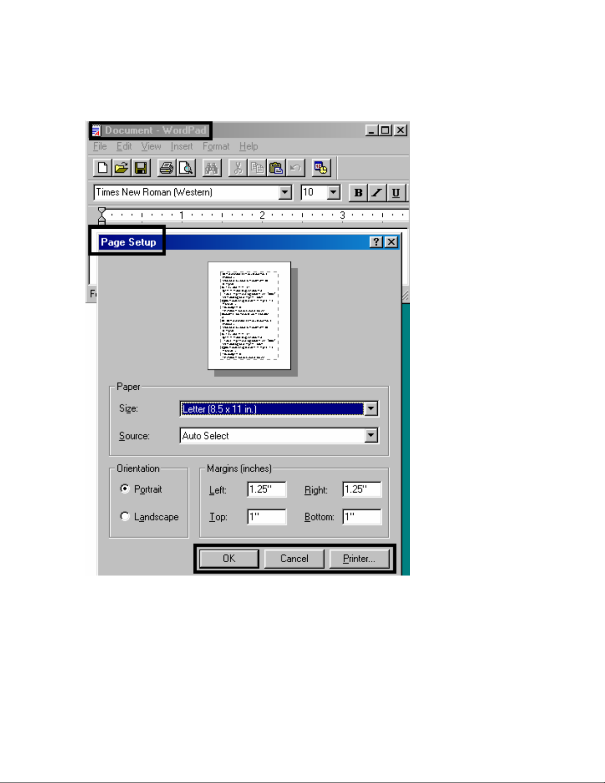
RESTRICTED USE ONLY Fargo Electronics, Inc.
Resolving the Printer not reading Encoded Magnetic Track Data (continued)
See the previous procedure in this section.
DTC500 Series Card Printer/Encoders User Guide (Rev. 6.0)
80
Page 99

RESTRICTED USE ONLY Fargo Electronics, Inc.
Resolving the Magnetic Stripe Data being printed on a Card
problem
Step Procedure
1 Confirm that the application is formatting the magnetic string correctly. See the
Sending the Track Information procedure in Section 3, page 177.
2
Use WordPad (a Windows 95/ 98/ ME/ NT/ 2000/XP word processing program
in the Accessories Program Group). See previous page for display.
a. Open the program and type: “~1%JULIEANDERSON^1234567890?”
b. Select File > Page Setup and click on the Printer button.
c. Ensure that the DTC500 Series Card Printer is selected and click OK.
d. Change all the margin settings to zero (0) and click OK.
e. Go to File on Menu Bar and select Print. (Note: The Printer should then
feed a card into the Encoder and magnetically encode it.)
DTC500 Series Card Printer/Encoders User Guide (Rev. 6.0)
81
Page 100

RESTRICTED USE ONLY Fargo Electronics, Inc.
Printing Process Errors
Resolving the Ribbon Alignment Error Message
Step Procedure
1 Check that the Ribbon is loaded properly and completely seated on the hubs.
2 Check that the marks on the Ribbon are complete.
3 a. Check the Motor operation to ensure that the Ribbon moves in both
Forward and Backward directions on Power Up.
b. Check the Ribbon types using the LCD.
4 Test the Ribbon Sensor.
a. Remove the back cover and locate the connector labeled J16 on the main
board.
b. Check the voltage for each of the five (5) Ribbon Sensors at their
connection to the Main Board.
c. Use a Multimeter to ground the negative lead to the chassis and put the
positive lead on pins 3, 5, 7, 9 and 11 of J16 on the main board.
d. Place a RibbonTraq™ mark over the Ribbon Sensor. (Note: The voltage
should be less than 1 VDC.)
e. Remove the RibbonTraq mark from the Ribbon Sensor. (Note: The
voltage should be greater than 4 VDC.)
f. Replace the Sensor if the voltages are incorrect. See the Replacing the
Ribbon Sensor Array Assembly (840108) procedure in Section 5, page
Error! Bookmark not defined..
5
6 Clear the jam and reboot the Printer if the Ribbon is jammed.
7 Repair the Ribbon.
Install a new Ribbon and press the Resume button to continue if the Ribbon is
out.
a. Repair the Ribbon by taping it back on to the take-up core if the Ribbon is
broken.
b. Press the Resume button to continue or Cancel to reset the Printer.
DTC500 Series Card Printer/Encoders User Guide (Rev. 6.0)
82
 Loading...