

Page 1

Pro-LX Laminating Card
Printer/Encoder User Guide (Rev.
4.0)
Part Number: L000700
Page 2

RESTRICTED USE ONLY Fargo Electronics, Inc.
Pro-LX Laminating Card Printer/Encoder User Guide (Rev. 4.0), property of FARGO
Electronics, Incorporated
Copyright 2002, 2003, 2004, 2005, 2006 by FARGO Electronics, Incorporated. All rights
reserved. Printed in the United States of America. Exclusive permission is granted to
authorized resellers of FARGO products to reproduce and distribute this copyrighted
document to authorized FARGO customers, who have signed a “no disclosure agreement”
regarding the restricted, proprietary use of said document.
The revision number for this document will be updated to reflect changes, corrections,
updates, and enhancements to this document.
Revision Control
Date Document Title
Number
Revision 4.0 15 September 2003 Pro-LX Laminating Card Printer/Encoder
User Guide (Rev. 4.0)
These reference documents were thoroughly reviewed to provide FARGO with professional
and international standards, requirements, guidelines, and models for our technical, training,
and user documentation. At all times, the Copyright Protection Notice for each document
was adhered to within our FARGO documentation process. This reference to other
documents does not imply that FARGO is an ISO-certified company at this time.
ANSI/ISO/ASQ Q9001-2000 American National Standard, (sub-title) Quality Management
Systems - Requirements (published by the American Society of Quality, Quality Press,
P.O. Box 3005, Milwaukee, Wisconsin 53201-3005)
The ASQ ISO 9000:2000 Handbook (editors, Charles A. Cianfrani, Joseph J. Tsiakals,
and John E. West; Second Edition; published by the American Society of Quality, Quality
Press, 600 N. Plankinton Avenue, Milwaukee, Wisconsin 53203)
Juran's Quality Handbook (editors, Joseph M. Juran and A. Blanton Godfrey; Fifth
Edition, McGraw-Hill)
Any questions regarding changes, corrections, updates, or enhancements to this document
should be forwarded to:
FARGO Electronics, Incorporated
Support Services
6533 Flying Cloud Drive
Eden Prairie, MN 55344 (USA)
(952) 941-9470
(800) 459-5636
FAX: (952) 941-7836
www.fargo.com
E-mail: sales@fargo.com
Pro-LX Laminating Card Printer/Encoder User Guide (Rev. 5.0) 2
Page 3

RESTRICTED USE ONLY Fargo Electronics, Inc.
How to use the manual
The Pro-LX Laminating Card Printer/Encoder User Guide (Rev. 4.0) is, in fact, the
troubleshooting and field service manual for the entire Pro-LX Card Printer. The manual is
designed to provide installers and technicians with quick, efficient lookup of related
procedures, components, and terms. The manual can be used effectively in either soft or
hard copy, depending on the preference of the installer or technician.
Manual Description
Sequence of Operations,
Glossary of Terms, and
Technical/Functional
Specifications (hyper-linked)
Table of Contents (hyperlinked)
Troubleshooting,
Replacement, Removal,
Diagnostic, and Navigation
Procedures (in hyper-linked
Sections)
Cross-Referencing (hyperlinked)
Comprehensive Index
(hyper-linked)
You can go directly to the Sequence of Operations,
Glossary of Terms, Technical Specifications, and
Functional Specifications to learn how to use the
processes, procedures, functions, and windows for the
Pro-LX Laminating Card Printer/Encoder within concise,
correlative tables.
You can use the automated Table of Contents to quickly
locate, for example, an error message, a procedure, the
index, or an appendix.
You can go directly to Specifications (Section 1), General
Troubleshooting (Section 2), Printer Adjustments (Section
3), Parts Replacement (Section 4), Printer Packing
(Section 5), and Board Level Diagnostics (Section 6) to
find troubleshooting, removal, and replacement
procedures. The section titles are always labeled
according to their function for consistent usage.
You can use the cross-referencing links to quickly locate,
for example, an error message or a procedure.
You can use the COMPREHENSIVE INDEX to quickly
locate information on the Pro-LX Laminating Card
Printer/Encoder, relating to a specification, a procedural
step, a window or screen, a component, a term, a qualifier,
or a related feature to this printer.
Appendices You can use Appendix A and B to locate information
relating to engineering drawings and technical updates,
which are specific to the Pro-LX Laminating Card
Printer/Encoder.
Pro-LX Laminating Card Printer/Encoder User Guide (Rev. 5.0) 3
Page 4
RESTRICTED USE ONLY Fargo Electronics, Inc.
Safety Messages (review carefully)
Symbol Critical Instructions for Safety purposes
Danger:
Caution:
Failure to follow these installation guidelines can result in death or
serious injury.
Information that raises potential safety issues is indicated by a warning
symbol (as shown to the below).
To prevent personal injury, refer to the following safety messages
before performing an operation preceded by this symbol.
To prevent personal injury, always remove the power cord prior to
performing repair procedures, unless otherwise specified.
To prevent personal injury, make sure only qualified personnel
perform these procedures.
This device is electrostatically sensitive. It may be damaged if
exposed to static electricity discharges.
Information that raises potential electrostatic safety issues is indicated
by a warning symbol (as shown to the below).
To prevent equipment or media damage, refer to the following
safety messages before performing an operation preceded by this
symbol.
To prevent equipment or media damage, observe all established
Electrostatic Discharge (ESD) procedures while handling cables in
or near the Circuit Board and Printhead Assemblies.
To prevent equipment or media damage, always wear an
appropriate personal grounding device (e.g., a high quality wrist
strap grounded to avoid potential damage).
To prevent equipment or media damage, always remove the Pro-
LX Ribbon and Cards from the printer before making any repairs,
unless otherwise specified.
To prevent equipment or media damage, take jewelry off of
fingers and hands, as well as thoroughly clean hands to remove oil
and debris before working on the printer.
Pro-LX Laminating Card Printer/Encoder User Guide (Rev. 5.0) 4
Page 5

RESTRICTED USE ONLY Fargo Electronics, Inc.
13254
8
9
15
242526272829303132
30
30
Pro-LX Laminating Card Printer/Encoder Overview
Reviewing Pro-LX Block Diagram
42
6
22
21
7
23
36
19
20
13
33
10
11
14
12
40
41
38
37
16
17
39
18
34
35
Motors Sensors Parts
1 Card Feed 8 Card Feed 25 Input Stack
2 Print Stepper 9 Print TOF (Top Of Form) 26 Card Feed Roller
3 Ribbon Drive 10 Ribbon Encoder Wheel 27 Cleaning Roller
4 Print Headlift 11 Ribbon Core ID 28 Cleaning Tape
5 Lamination Stepper 12 Ribbon Sensor 29 Print Platen
6 Lamination Drive 13 Head Lift 30 Print Drive Rollers
7 Lamination Headlift 14 Thermistor 31 Printhead
15 Print Cover Interlock 32 Print Encoder Wheel
16 Lamination TOF 33 Flipper Clutch
17 Flipper Home 34 Encode Section
18 Mag Feed TOF 35 Mag Drive Roller
19 Lam Encoder Wheel 36 Lam Encoder Wheel
20 Lam Core ID 37 Lam Platen Roller
21 Laminate Ribbon Sensor 38 Lam Drive Rollers
22 Lam Headlift 39 Flipper Drive Roller
23 Thermocouple 40 Lam Roller
24 Lam Cover Interlock 41 Flattener Roller
42 Printhead Cooling Fan
Pro-LX Laminating Card Printer/Encoder User Guide (Rev. 5.0) 5
Page 6

RESTRICTED USE ONLY Fargo Electronics, Inc.
Reviewing Pro-LX Boot Up Sequence
Step Process
1 On Power up, print and the Lam Stepper Motor engage.
2 Print and Lamination Headlift Sensor checks for current open/closed state.
If either Sensor registers closed, the appropriate Headlift Motor engages until
Headlift Sensor detects open state.
3 Check SmartCard and Mag Sensors for presence of card.
If there is a card found in either location, the print and Lam Stepper Motors engage
to back the card out onto the flipper table.
4 Print TOF, Card Detection and LAM TOF Sensors check for presence of card.
If any Sensor finds a card, the card is fed onto the flipper table. The flipper table
then rotates and ejects the card into the reject bin.
5 The Flipper Clutch activates.
6 The Lam Stepper Motor engages.
7 The Flipper Home Sensor detects the homing flag and the Flipper Table levels.
8 The Flipper Clutch disengages
9 The Lam Stepper Motor disengages.
Pro-LX Laminating Card Printer/Encoder User Guide (Rev. 5.0) 6
Page 7

RESTRICTED USE ONLY Fargo Electronics, Inc.
Reviewing Pro-LX Sequence of Operations
The following sequence describes a dual sided full color print job with magnetic encoding
and single sided Lamination.
Step Process
1 The File information is received from the PC
2 The Printer checks the installed Ribbon type stored in memory against the Ribbon
type command that was sent from the printer.
a. If Ribbon type does not match, a Wrong Ribbon Error is displayed on the
LCD.
3 The Card Input Motor and Print Stepper Motor engage.
4 The Card detection Sensor detects leading edge of card and disengages the card
input Motor.
5 The Print Stepper drives card to the Print TOF Sensor. The Print Stepper
disengages
6 The Print Ribbon drive engages.
7 The Print Ribbon Sensor looks for the color transition from Yellow to Magenta.
The Print Ribbon Encoder detects number of revolutions required to use an entire
color panel.
8 The Print Stepper Motor engages.
9 The Print TOF Sensor detects trailing edge of card.
10 The Print Stepper Motor queues card to the middle of the platen roller. All Stop
11 The Print Headlift Motor engages.
12 The Print Headlift Sensor detects closed state.
13 The Print Headlift Motor disengages.
14 The Print Stepper Motor engages.
Continued on the next page.
Pro-LX Laminating Card Printer/Encoder User Guide (Rev. 5.0) 7
Page 8

RESTRICTED USE ONLY Fargo Electronics, Inc.
Reviewing Pro-LX Sequence of Operations (continued)
Step Process
15 The Print Cover Sensor checks for a closed state.
16 The Ribbon Drive Motor engages.
17 The Image Data is burned by the printhead until image data is depleted. All Stop.
18 The Thermistor engages Printhead Cooling Fan to maintain proper operating
temperature.
19 The Headlift Motor engages.
20 The Print Headlift Sensor detects an open state.
21 The Print Headlift Motor disengages.
22 The Print Stepper Motor engages.
23 The Print Ribbon drive engages.
24 After the Ribbon advances a few encoder clicks, assume the Ribbon is free of
cards. All Stop.
25 Repeat steps 10 through 24 for the appropriate number of color and overlay
panels.
26 The Print and the Lamination Drive Stepper Motors engage.
27 The Lamination Card Sensor detects presence of card. All Stop.
28 The Lam Stepper engages.
29 The Card feeds back to the Flipper Table.
30 The Flipper Clutch engages
31 The Flipper Table rotates 180 degrees
32 The Flipper Table Clutch disengages. All Stop.
33 The Print and Lam Stepper Motors are activated.
Continued on the next page.
Pro-LX Laminating Card Printer/Encoder User Guide (Rev. 5.0) 8
Page 9

RESTRICTED USE ONLY Fargo Electronics, Inc.
Reviewing Pro-LX Sequence of Operations (continued)
Step Process
34 The card is fed past the Print TOF Sensor. All Stop.
35 The Flipper Table Clutch engages.
36 The Lamination Stepper engages.
37 The Flipper table rotates to level. All Stop.
38 Repeat steps 10 through 18 for appropriate number of color/overlay panels.
39 The Print and Lamination drive Stepper Motors engage.
40 The Lamination Card Sensor detects presence of card. All Stop.
41 The Lam Stepper engages.
42 The Card feeds back to the flipper table.
43 The Flipper Clutch engages
44 The Flipper Table rotates to encoding angle.
45 The Flipper Table Clutch disengages. All Stop.
46 The Print and Lamination Stepper Motors activate.
47 The Encoding TOF Sensor detects leading edge of card.
48 The Card feeds to below the magnetic encoder head. All Stop.
49 The Print and Lamination Stepper Motors are engaged.
50 The Magnetic Encoding Head is activated.
51 The Card feeds to the Encoding TOF Sensor. All Stop.
52 Repeat steps 40 through 45 for each verification pass.
53 The Card is fed onto the Flipper Table.
Continued on the next page.
Pro-LX Laminating Card Printer/Encoder User Guide (Rev. 5.0) 9
Page 10

RESTRICTED USE ONLY Fargo Electronics, Inc.
Reviewing Pro-LX Sequence of Operations (continued)
Step Process
54 The Flipper Clutch engages.
55 The Flipper table returns to level.
56 The Flipper Clutch disengages.
57 The Card feeds back to Print TOF Sensor then forward to the Lamination card
Sensor. All Stop.
58 The Laminate Ribbon Drive activates until Laminate Ribbon Sensor detects patch
mark.
At this time the Thermocouple is checking the temperature of the Laminate roller
and activating the heater core if needed.
59 The Lamination Stepper is activated.
60 The Card is fed to the platen roller. All Stop
61 The Lamination Cover Sensor checks for closed state.
62 The Headlift Motor engages.
63 The Headlift Sensor detects closed state.
64 The Headlift Motor disengages.
65 The Lamination Stepper Motor and Laminate Ribbon drive engage for the distance
of the card. All Stop.
66 The Headlift Motor engages.
67 The Headlift Sensor detects open state.
68 The Headlift Motor disengages.
69 The Lamination Stepper Motor is activated and card is fed out of the printer.
Pro-LX Laminating Card Printer/Encoder User Guide (Rev. 5.0) 10
Page 11

RESTRICTED USE ONLY Fargo Electronics, Inc.
Table of Contents
How to use the manual _________________________________________________________________3
Safety Messages (review carefully)________________________________________________________4
Pro-LX Laminating Card Printer/Encoder Overview __________________________________________5
Reviewing Pro-LX Block Diagram _____________________________________________________5
Reviewing Pro-LX Boot Up Sequence __________________________________________________6
Reviewing Pro-LX Sequence of Operations_______________________________________________7
Section 1: Specifications________________________________________________________ 15
Regulatory Compliances _______________________________________________________________15
Agency Listings______________________________________________________________________16
Technical Specifications _______________________________________________________________16
Functional Specifications ______________________________________________________________19
Printer Components: Top Cover to Power Port___________________________________________20
Printer Components: Centronics-Type Parallel Interface ___________________________________24
Printer Components: Print Ribbons ____________________________________________________25
Printer Components: Resin-Only Print Ribbons __________________________________________26
Printer Components: Dye-Sublimation-Only Print Ribbons _________________________________27
Printer Components: Blank Cards _____________________________________________________29
Reviewing the upgraded 81754 PVC Cards ______________________________________________31
Printer Components: Laminator ______________________________________________________33
Visual Security Solutions (Specifications) _________________________________________________34
VeriMarkTM Cards - 2-D holographic foil application _____________________________________34
Custom HoloMarkTM Cards _________________________________________________________34
Visual Security - Card Stock Part Numbers ______________________________________________34
Visual Security - Fargo Certified Overlaminates (Special Order in 50 quantity minimum)__________34
Visual Security Card Stock - Tolerances ________________________________________________35
VeriMarkTM - Application Specifications_______________________________________________35
HoloMarkTM and Custom HoloMarkTM - Application Specifications ________________________35
Section 2: General Troubleshooting______________________________________________ 36
LCD/SmartGuard Messages ____________________________________________________________36
Reviewing the Top Line LCD Messages ________________________________________________36
Reviewing the Bottom Line LCD Error / Status Messages __________________________________40
Communications Errors________________________________________________________________43
Resolving the Communication Errors___________________________________________________43
Card Feeding Errors __________________________________________________________________46
Resolving the Card Feeding Errors_____________________________________________________46
Resolving the Flipper Jam Error Message _______________________________________________48
Print Process Errors___________________________________________________________________49
Resolving the Headlift Error Message __________________________________________________49
Resolving the Cover Open Error Message _______________________________________________50
Resolving the Blank Output issues _____________________________________________________51
Card Jam Errors______________________________________________________________________53
Resolving the Card Jam: Print Error Message____________________________________________53
Resolving the Card Jam: Mag Error / Smart Error Message _________________________________54
Resolving the Card Jam: Lam Error Message ____________________________________________55
Resolving the Card Jam: Flip Error Message_____________________________________________56
Ribbon Errors _______________________________________________________________________57
Resolving the Lam Error/Out Error Message_____________________________________________57
Resolving the Skipping Ribbon Panel issues _____________________________________________59
Resolving the Wrong Ribbon error (being displayed incorrectly) _____________________________62
Resolving the Ribbon Low Message ___________________________________________________63
Resolving the Ribbon Breaking issues __________________________________________________64
Resolving the Lamination (not adhering to the card surface) problem__________________________67
Pro-LX Laminating Card Printer/Encoder User Guide (Rev. 5.0) 11
Page 12

RESTRICTED USE ONLY Fargo Electronics, Inc.
Encoding Errors______________________________________________________________________69
Resolving the Mag Verify Error Message _______________________________________________69
Resolving data intended for the Magnetic Stripe (being printed on the card) problem _____________72
Diagnosing Image Problems ____________________________________________________________73
Resolving the Pixel Failure problems___________________________________________________73
Resolving the Card Surface Debris problems_____________________________________________74
Resolving the Incorrect Image Darkness problems ________________________________________75
Resolving the Ribbon Wrinkle problems ________________________________________________77
Resolving the Excessive Resin Printing problems _________________________________________79
Resolving the Incomplete Resin Printing problems ________________________________________81
Resolving the Image Placement problems _______________________________________________82
Resolving the Poor Image Quality problems _____________________________________________86
Running the Self Test _________________________________________________________________87
Running the Standard Self Test Print ___________________________________________________87
Reviewing the Main Circuit Board_____________________________________________________88
Using the DIP Switch (Self-test) ______________________________________________________89
Setting the DIP Switch Settings _______________________________________________________91
Running the 15-Shade Self Test _______________________________________________________92
Interfacing Information ________________________________________________________________93
Reviewing the Pin Assignments _______________________________________________________93
Reviewing the Centronics Parallel Pin Assignments _______________________________________94
Reviewing the Printer Timing Diagram _________________________________________________96
Reviewing the Printer Timing ________________________________________________________97
Section 3: Printer Adjustments__________________________________________________ 98
Safety Messages (review carefully)_______________________________________________________98
Using the Settings dialog box ___________________________________________________________99
Using the Image Darkness option_____________________________________________________100
Using the Image Placement option ____________________________________________________101
Using the Print Length option________________________________________________________102
Using the Magnetic Offset option_____________________________________________________103
Using the Flipper Offset option ______________________________________________________104
Using the Lamination Placement option________________________________________________105
Adjusting the Card Flattener_________________________________________________________107
Adjusting the Laminator____________________________________________________________109
Printer Driver Options________________________________________________________________111
Using the Calibrate tab _______________________________________________________________112
Using Image Position controls _______________________________________________________113
Using the Lamination Position control _________________________________________________115
Using the Sensors and Settings buttons ________________________________________________116
Using the Magnetic Encoding tab _______________________________________________________118
Using the Encoding Mode option _____________________________________________________120
Using the Coercivity option _________________________________________________________121
Using the Magnetic Track Selection option _____________________________________________121
Reviewing the Enable MLE Support checkbox __________________________________________123
Using the Magnetic Track Options____________________________________________________124
Using the Bit Density radio buttons ___________________________________________________125
Using the Character Size radio buttons_________________________________________________125
Using the ASCII Offset ____________________________________________________________126
Using the LRC Generation radio buttons _______________________________________________127
Using the Character Parity radio buttons _______________________________________________127
Using the Verification radio buttons___________________________________________________128
Using the Shift Data Left checkbox ___________________________________________________129
Using the Encode Before Print checkbox _______________________________________________129
Reviewing ISO Track Locations _____________________________________________________130
Sending Track Information__________________________________________________________131
Pro-LX Laminating Card Printer/Encoder User Guide (Rev. 5.0) 12
Page 13

RESTRICTED USE ONLY Fargo Electronics, Inc.
Entering Track Information _________________________________________________________131
Reviewing Tracks 1, 2 and 3 (in table format) ___________________________________________132
Reviewing the Track Data Note ______________________________________________________132
Reviewing the ASCII Code and Character Table_________________________________________133
Using the Lamination tab _____________________________________________________________134
Selecting from the Lamination Side dropdown menu _____________________________________135
Selecting from the Lamination Type dropdown menu _____________________________________136
Selecting Lamination Dwell Time and Temperature ______________________________________138
Using the Overlay / Print Area tab ______________________________________________________139
Using the Overlay / Print Area dropdown menu _________________________________________140
Using the Overlay / Print Area _______________________________________________________141
Using Security Options (Visual Security Solutions)_______________________________________147
Selecting Orientation - Landscape under Card tab ________________________________________148
Selecting the Visual Security Solutions dropdown menu (A to D) ___________________________149
Selecting Orientation - Portfolio under Card tab _________________________________________150
Selecting the Visual Security Solutions dropdown menu (E to H)____________________________151
Selecting the VeriMark radio button __________________________________________________152
Selecting the HoloMark radio button __________________________________________________153
Reviewing the Custom VeriMark Card (Custom Graphic in a 2D foil) ________________________154
Reviewing the Custom HoloMark Card (Custom Graphic in a 2D foil) _______________________155
Using SmartShield Area dropdown menu ______________________________________________156
Using the Image Color tab_____________________________________________________________157
Using the K Panel Resin tab _________________________________________________________159
Selecting from the Print All Black With K Panel options __________________________________160
Selecting the Full Card option _______________________________________________________161
Selecting the Defined Area(s) option __________________________________________________162
Selecting the Undefined Area(s) option ________________________________________________163
Using the Defined Area(s) function ___________________________________________________164
Using the Device Options tab __________________________________________________________173
Selecting the Ribbon Type __________________________________________________________174
Selecting from the Color Matching options _____________________________________________175
Selecting from the Resin Dither dropdown menu_________________________________________176
Selecting the Print Both Sides checkbox _______________________________________________177
Selecting the Split 1 Set of Ribbon Panels checkbox ______________________________________178
Using the Print Back Side First option _________________________________________________179
Selecting the Print Back Side Only checkbox ___________________________________________180
Selecting the Rotate Front 180 Degrees checkbox ________________________________________180
Selecting the Rotate Back 180 Degrees checkbox ________________________________________180
Selecting the Buffer Single Card checkbox _____________________________________________181
Selecting the Disable Printing checkbox _______________________________________________181
Selecting the Pause for Low Ribbon checkbox __________________________________________182
Using the Card tab___________________________________________________________________183
Selecting the Card Size_____________________________________________________________183
Selecting the Orientation ___________________________________________________________183
Determining the number of Copies____________________________________________________183
Clicking on the Test Print button _____________________________________________________183
Clicking on the About button ________________________________________________________184
Section 4: Cleaning___________________________________________________________ 185
Cleaning the Printhead _____________________________________________________________186
Cleaning the Card Feed Rollers ______________________________________________________187
Replacing the Cleaning Tape ________________________________________________________189
Cleaning the Platen Rollers _________________________________________________________191
Cleaning the Printer’s Exterior _______________________________________________________192
Cleaning the Printer’s Interior _______________________________________________________192
Cleaning the Magnetic Encoder ______________________________________________________193
Pro-LX Laminating Card Printer/Encoder User Guide (Rev. 5.0) 13
Page 14

RESTRICTED USE ONLY Fargo Electronics, Inc.
Section 5: Packing the Pro-LX Card Printer______________________________________ 194
Section 6: Board Level Diagnostics ______________________________________________ 195
Board Errors _______________________________________________________________________195
Resolving the EE Memory Error _____________________________________________________195
Resolving the EE Checksum Error____________________________________________________195
Resolving the DRAM Memory Error__________________________________________________196
Sensor Testing______________________________________________________________________196
Reviewing the Sensor Location and Voltages ___________________________________________197
Reviewing the Motor Voltages (when active) ___________________________________________198
Section 7: Fargo Technical Support_____________________________________________ 199
Contacting Fargo Technical Support_____________________________________________________199
Reading the Serial Numbers on a Fargo printer ____________________________________________200
Finding out when a Fargo Card Printer was manufactured _________________________________200
Reviewing Example No. 1: Serial Number 80453289_____________________________________200
Reviewing Example No. 2: Serial Number A1280224 ____________________________________200
Section 8: Reviewing the Spare Parts List________________________________________ 201
Glossary of Terms ____________________________________________________________ 202
Index_______________________________________________________________________ 222
Pro-LX Laminating Card Printer/Encoder User Guide (Rev. 5.0) 14
Page 15

RESTRICTED USE ONLY Fargo Electronics, Inc.
Section 1: Specifications
The purpose of this section is to provide the User with specific information on the Regulatory
Compliances, Agency Listings, Technical Specifications and Functional Specifications for the
Pro-LX Laminating Card Printer/Encoder (Rev. 3.0).
Regulatory Compliances
Term Description
CSA The Printer manufacturer has been authorized by UL to represent
the Card Printer as CSA Certified under CSA Standard 22.2.
File Number: E145118
FCC The Card Printer complies with the requirements in Part 15 of the
FCC rules for a Class B digital device. (Note: These
requirements are designed to provide reasonable protection
against harmful interference in a residential installation.)
If equipment operation in a residential area causes unacceptable
interference to radio and TV reception, the operator is required to
take whatever steps are necessary to correct the interference.
ITS-EMC The Card Printer has been tested and complies with EN55022
Class B: 1995 and EN82082-1: 1997 standards for EMI
emissions.
(Note: Based on the above testing, the Printer manufacturer
certifies that the Card Printer complies with all current EMC
directives of the European Community and has placed the CE
mark on the Card Printer.)
License Number: J99032510
TÜV-GS The Card Printer has been tested and complies with IEC950 and
bears the TÜV-GS mark.
License Number: S9971826
UL The Card Printer is listed under UL 1950 INFORMATION
TECHNOLOGY EQUIPMENT.
File Number: E145118, Volume 1, Section 15
Pro-LX Laminating Card Printer/Encoder User Guide (Rev. 5.0) 15
Page 16

RESTRICTED USE ONLY Fargo Electronics, Inc.
Agency Listings
Term Description
Emissions
Standards
Safety
Standards
CE, FCC, CRC c1374, BSMI, ITS (EN 55022 Class B:1995, FCC
Class B, EN 82082-1:1997).
UL 1950, CSA C2.2 No.950-95 and TüV-GS (EN 60950 A1-A4, A11).
Technical Specifications
Term Description
Accepted
Standard Card
Size
Accepted Card
Thickness
Accepted Card
Types
Card Capacity 100 cards (30 mil).
Colors Up to 16.7 million colors and 256 shades per pixel.
CR-80: 3.375 in. x 2.125 in. (85.6mm x 54mm)
.020 in. (20 mil) to .040 in. (40 mil) (.508mm to 1.02mm).
PVC or Polyester cards with polished PVC finish
Dimensions 10.44 in. H x 24.79 in. W x 10.3 in. D (265mm x 630mm x 260mm).
Encoding
Options
Humidity 20% to 80% Non-Condensing.
Interface Centronics parallel, IEEE-1284 Compliant
Memory 4 MB RAM; expandable to 16 MB RAM.
Operating
Temperature
ISO Magnetic Stripe Encoding Module, dual high- and low-
coercivity, Tracks 1, 2 and 3
JIS II Magnetic Stripe Encoding Module
E-card Docking Station (required for 3rd party smart card encoding)
65ºF to 80ºF (18ºC to 27ºC).
Pro-LX Laminating Card Printer/Encoder User Guide (Rev. 5.0) 16
Page 17

RESTRICTED USE ONLY Fargo Electronics, Inc.
Technical Specifications (continued)
Term Description
Overlaminate
Options
Thermal Transfer Overlaminate, .25 mil thick, 500 prints
PolyGuard Overlaminate, .6 mil thick, 250 prints
PolyGuard Overlaminate, 1.0 mil thick, 125 prints
All overlaminates available in either clear, holographic globe design or
custom holographic design; can also be optimized for use with smart
cards and Magnetic Stripes
Printing Method Dye Sublimation/Resin Thermal Printer
Printing
300 dpi (11.8 dots/mm).
Resolution
Print SpeedBatch Mode
8 seconds per card / 450 cards per hour (K)*
15 seconds per card / 240 cards per hour (BO)*
30 seconds per card / 120 cards per hour (YMCKO)*
30 seconds per card / 120 cards per hour (YMCK/lamination)
37 seconds per card / 97 cards per hour (YMCKK/lamination)
Print speed indicates an approximate batch print speed and is
measured from the time a card feeds into the Printer to the time it
ejects from the Printer.
Print speeds do not include the time needed for the PC to process the
image.
Process time is dependent on the size of the file, the CPU, amount of
RAM and the amount of available resources at the time of the print.
(Note: The single card print speeds will be slower than the batch print
speeds listed above since batch print speed is enhanced by the
Printer's multi-tasking capabilities when printing multiple cards in
succession.)
Pro-LX Laminating Card Printer/Encoder User Guide (Rev. 5.0) 17
Page 18

RESTRICTED USE ONLY Fargo Electronics, Inc.
Technical Specifications (continued)
Term Description
Print Ribbon
Options
Full Color with resin black, YMCKO*, 250 prints
Full Color with two resin black panels, YMCKOK*, 250 prints
Full Color with resin black, no overlay panel, YMCKK*, 250 prints,
must be used with overlaminate
Dye-Sublimation black, BO*, 500 prints
Resin black, green, blue, red, white, silver, gold, scratch-off, 1000
prints
*Indicates the ribbon type and the number of ribbon panels printed
where Y=Yellow, M=Magenta, C=Cyan, K=Resin Black, O=Overlay,
B=Dye-Sublimation Black
Print Area CR-80 edge to edge (3.37”L x 2.11”W / 85.5mmL x 53.5mmW)
Supply Voltage 100 to 240 V ac.
Supply
50 Hz/60 Hz.
Frequency
Software Drivers Windows 95/ 98/ ME/ NT/ 2000/XP.
System
Requirements
IBM-PC or compatible. Windows 95/ 98/ ME/ NT/ 2000/XP. Pentium™
class 133 MHz computer with 32 MB of RAM or higher, 200 MB free
hard disk space or higher and ECP parallel port with DMA access.
Warranty Printer - One year; optional Extended Warranty Program (U.S. only)
Printhead - One year, unlimited pass with UltraCard cards
Weight 40 lbs. (18.2kg).
Kits, Adapters
and Cable
16MB RAM Upgrade Kit
Printer Cleaning Kit
Ethernet Interface Adapter (Windows only; required for stand-alone
networking of Printers)
USB-to-Parallel Interface Cable (Windows 98/ME/2000/XP only)
Pro-LX Laminating Card Printer/Encoder User Guide (Rev. 5.0) 18
Page 19

RESTRICTED USE ONLY Fargo Electronics, Inc.
Functional Specifications
The Card Printer utilizes two different, yet closely related printing technologies to achieve its
remarkable direct-to-card print quality for dye-sublimation and resin thermal transfer. (Note:
The Card Printer will print from any IBM-PC® or compatible running Windows® 95/98/ME,
Windows NT 4.0, Windows 2000 or Windows XP.)
The following describes how each of these technologies works:
Function Description
DyeSublimation
Resin
Thermal
Transfer
Dye-Sublimation is the print method the Pro-LX Laminating Card
Printer/Encoder uses to produce smooth, continuous-tone, photographic
images. This process uses a dye-based ribbon roll that is partitioned by a
number of consecutive color panels.
The panels are grouped in a repeating series of these three process
colors along the entire length of the Print Ribbon: yellow, magenta and
cyan (YMC).
The Printer always prints the yellow panel (first), the magenta panel
(second) and the cyan panel (third).
As the Print Ribbon passes beneath the Printhead, thermal elements
within the Printhead heat the dyes on the ribbon. (Note: When these
dyes are heated, the dyes vaporize and diffuse into the surface of the
card. A separate pass is made for each of the three color panels on the
ribbon.)
By combining the colors of each panel and by varying the heat used to
transfer these colors, it is possible to print up to 16.7 million different
shades of color. This blends one color smoothly into the next, producing
photo-quality images with no dot pattern.
Resin Thermal Transfer is the print method the Printer uses to print sharp
black text and crisp bar codes that can be read by both infrared and visiblelight bar code scanners.
Like dye-sublimation, this process uses the same thermal Printhead to
transfer color to a card from a resin-only Print Ribbon or the resin black (K)
panel of a full color Print Ribbon.
The difference, however, is that solid dots of resin-based ink are
transferred and fused to the surface of the card to produce durable,
saturated printing.
Pro-LX Laminating Card Printer/Encoder User Guide (Rev. 5.0) 19
Page 20

RESTRICTED USE ONLY Fargo Electronics, Inc.
Printer Components: Top Cover to Power Port
Component Description
Print Top
Cover
Opens to allow access to the Printhead, Print Ribbon and card path.
(Note: This cover must be closed in order for the Printer to begin
printing.)
Lamination
Top Cover
Opens to allow access to the lamination roller, overlaminate and card
path. (Note: This cover must be closed in order for the Printer to begin
printing.)
Cover
Unlatches the Top Covers.
Release
Buttons
Printhead
Printer component that prints. (Note: This component is fragile and must
not be bumped or touched with anything other than a cleaning pen.)
Card
Cleaning
Cartridge
Automatically cleans cards for higher print quality. (Note: Replace the
Card Cleaning Tape within this assembly after every 1,500 cards or as
needed depending on the cleanliness of the card stock and the
environment in which the Printer is located. Replace this tape if the cards
start showing speckles or debris on the printed surface.)
LCD Display The LCD display shows the User the current status of the Printer. Since
the Printer's printing and laminating functions work independently, the top
line of the LCD reports the status of the printing functions, while the
bottom line reports the status of the laminating functions.
When the Printer is first powered ON, the Printer's startup screen will
appear displaying the current firmware version and the amount of
installed Printer memory (4MB or 16MB).
Once the Printer has finished its startup system check, it will then display
Printer Ready and Lam Ready to indicate that the Printer is ready for
operation. Lam Temp=XX% will display if the Printer's built-in laminator is
heating or cooling to its target temperature. When it reaches 100%,
lamination will begin.
During operation, the LCD will also indicate the specific ribbon panel
being printed, whether or not it is laminating and if any printing errors
have occurred.
On LED Light
Indicates the Printer power is either ON or OFF.
Pro-LX Laminating Card Printer/Encoder User Guide (Rev. 5.0) 20
Page 21

RESTRICTED USE ONLY Fargo Electronics, Inc.
Print Top Cover
Ready LED Light
Access Card Slot
Card Input Hopper
Rejection Card Hopper
Printer Components: Top Cover to Power Port (continued)
This table displays Printer components. Refer to the table in this section.
Printhead
Card Cleaning Cartridge
Lamination Top Cover
Cover Release
Buttons
Card Output Hopper
LCD Display
On LED Light
Pause/Resume
Button
On/Cancel
Button
Pro-LX Laminating Card Printer/Encoder User Guide (Rev. 5.0) 21
Card Thickness
Adjustment Slide
Page 22

RESTRICTED USE ONLY Fargo Electronics, Inc.
Printer Components: Top Cover to Power Port (continued)
Component Description
Ready LED
Light
On/Cancel
Button
Pause/
Resume
Button
When ON, this light indicates the Printer is ready for operation. When
OFF, this light indicates the Printer is either OFF or paused and will not
operate.
If this light is flashing, a Printer error has occurred. (Note: Refer to the
Printer's LCD display for the specific type of error that occurred. See the
Interpreting LCD Messages for a complete description of all possible LCD
error prompts.
The On/Cancel button turns the Printer power ON and OFF. It also
serves to cancel the current print job and reset the Printer for the next
print job if an unrecoverable print error has occurred.
If a card is left within the Printer after a print job is canceled, it will
automatically be ejected when the Printer is turned back ON. (Note:
With the Top Cover(s) open, this button can also be used to manually
rotate the feed Rollers forward. This is helpful when cleaning the Printer
or if clearing jammed media.)
The Pause/Resume button allows the User to pause the Printer at any
time during operation. Note, however, that the Printer will always finish its
current task before pausing.
If the Pause/Resume button is pressed in the middle of printing the
magenta ribbon panel, the Printer will pause only after the entire magenta
panel has printed. (Note: The Ready LED Light will turn OFF when the
Printer is paused and ON again when operation is resumed. With the Top
Cover(s) open, this button can also be used to manually rotate the feed
Rollers backward. This is helpful when cleaning the Printer or if clearing
jammed media.)
Access Card
Slot
This is the slot in which a SmartGuard Access Card is inserted when
using the Printer's included SmartGuard Security Feature. (Note: This
unique option prevents the Printer from operating unless a custom
access card is inserted. It also allows the User to print custom
SmartShield Security Images which glow under ultraviolet light.)
Card Input
Load blank cards into this Hopper.
Hopper
Pro-LX Laminating Card Printer/Encoder User Guide (Rev. 5.0) 22
Page 23

RESTRICTED USE ONLY Fargo Electronics, Inc.
Parallel Interface Port
Power Port
Printer Components: Top Cover to Power Port (continued)
Component Description
Card Thickness
Adjustment Slide
Card Output
Hopper
Rejection Card
Hopper
E-Card Docking
Station Port - For
Smart Card
Support
Parallel Interface
Port
Power Port Connects to the included power.
Adjusts the Printer to feed varying card thicknesses. See the
Resolving the Card Feeding Errors procedure in Section 2, page 46.
Stores printed cards; up to 100, 30 mil cards.
Stores cards that have not printed or encoded properly. Helps to
separate potential bad cards from a stack of good cards, which eject
into the Card Output Hopper. (Note: The Printer will automatically
eject cards into this Hopper if there is a printing error, encoding error
or if a card is left in the Printer after a print job is canceled or the
Printer restarted.)
Provided only if the Printer includes an optional E-Card Docking
Station. This is necessary for support of third party smart card
encoding features.
Connects to a Windows PC with a parallel cable.
E-Card Docking
Station Port
Pro-LX Laminating Card Printer/Encoder User Guide (Rev. 5.0) 23
Page 24
RESTRICTED USE ONLY Fargo Electronics, Inc.
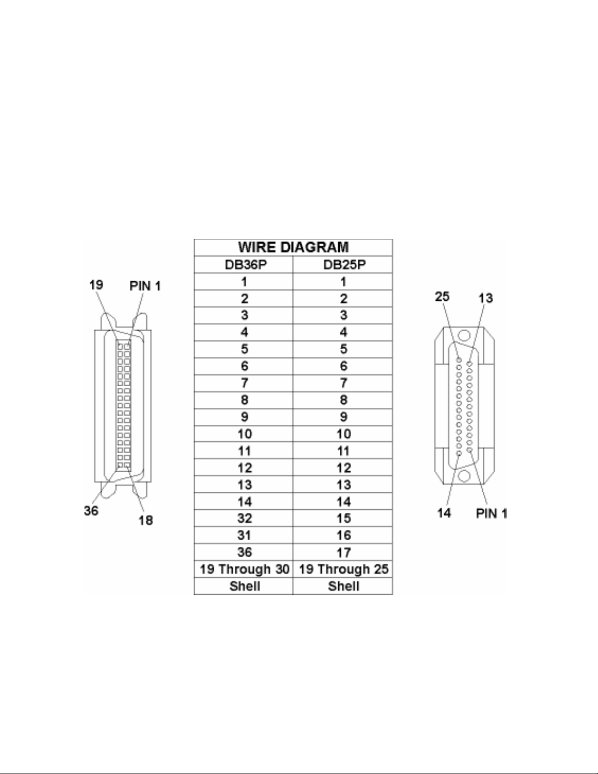
Printer Components: Centronics-Type Parallel Interface
The Card Printer is equipped with a standard 8-bit centronics-type parallel interface port. This
communication port is the means through which the Printer receives data from the computer.
This section describes the pin assignments and signal specifications for this port.
The Centronics-type parallel interface is the most widely used Printer interface due to its
simplicity, speed and standardization throughout the PC industry. The Printer's parallel
interface connector is a standard 36-pin Amp type with two metal-wire retaining clips and is
ECP (Extended Capabilities Port) compatible. It mates with a standard, bi-directional PC to
Printer parallel cable.
For best results, keep the interface cable to less than 6 feet in length.
Pro-LX Laminating Card Printer/Encoder User Guide (Rev. 5.0) 24
Page 25
RESTRICTED USE ONLY Fargo Electronics, Inc.
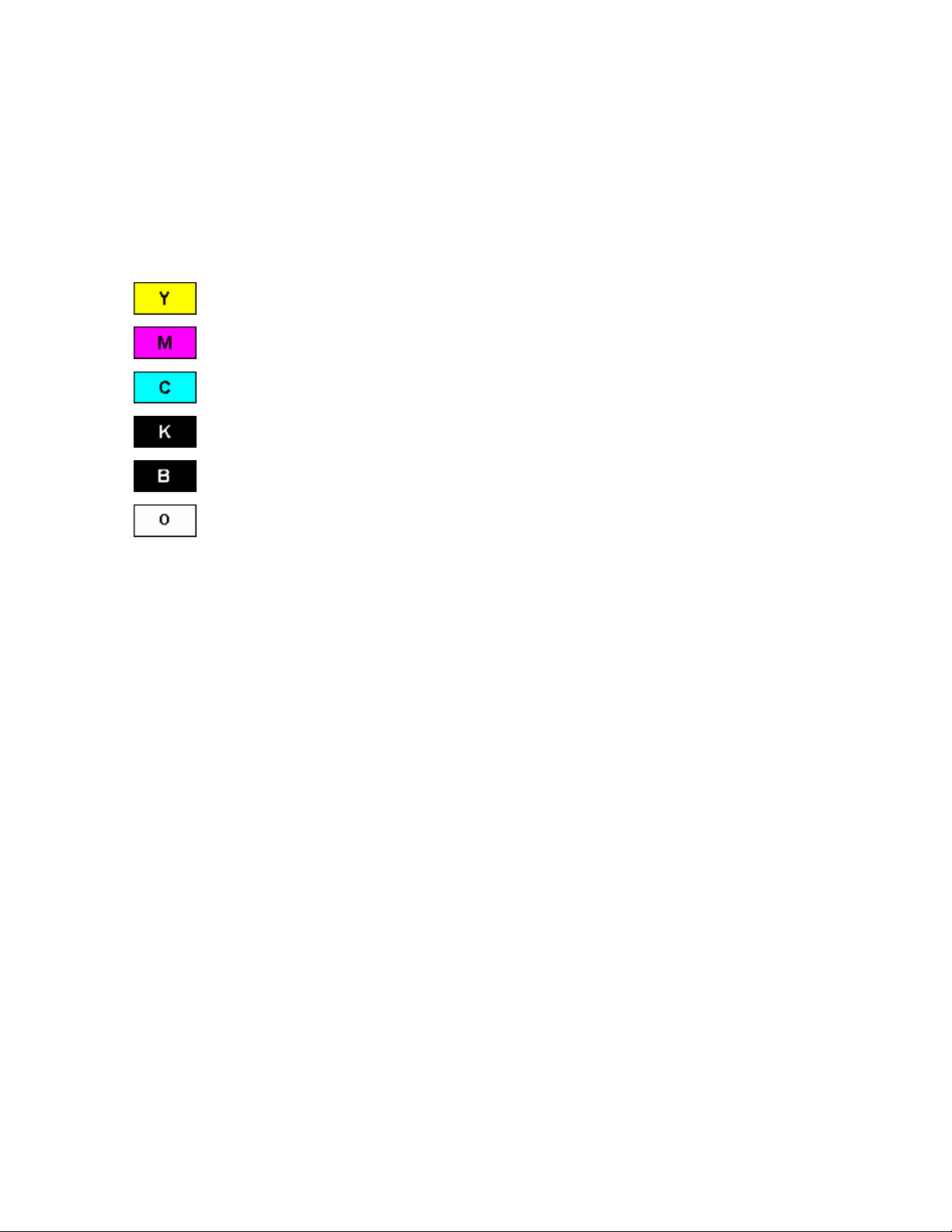
Printer Components: Print Ribbons
The Card Printer utilizes both dye-sublimation and/or resin thermal transfer methods to print
images directly onto blank cards. Since the dye-sublimation and the resin thermal transfer
print methods each provide their own unique benefits, Print Ribbons are available in resinonly, dye-sublimation-only and combination dye-sublimation/resin versions. (Note: A letter
code has been developed to indicate the type of ribbon panels found on each ribbon.)
This letter code is as follows:
= Dye-Sublimation Yellow Panel
= Dye-Sublimation Magenta Panel
= Dye-Sublimation Cyan Panel
= Resin Black Panel
= Dye-Sublimation Black Panel
= Clear Protective Overlay Panel
Pro-LX Laminating Card Printer/Encoder User Guide (Rev. 5.0) 25
Page 26
RESTRICTED USE ONLY Fargo Electronics, Inc.
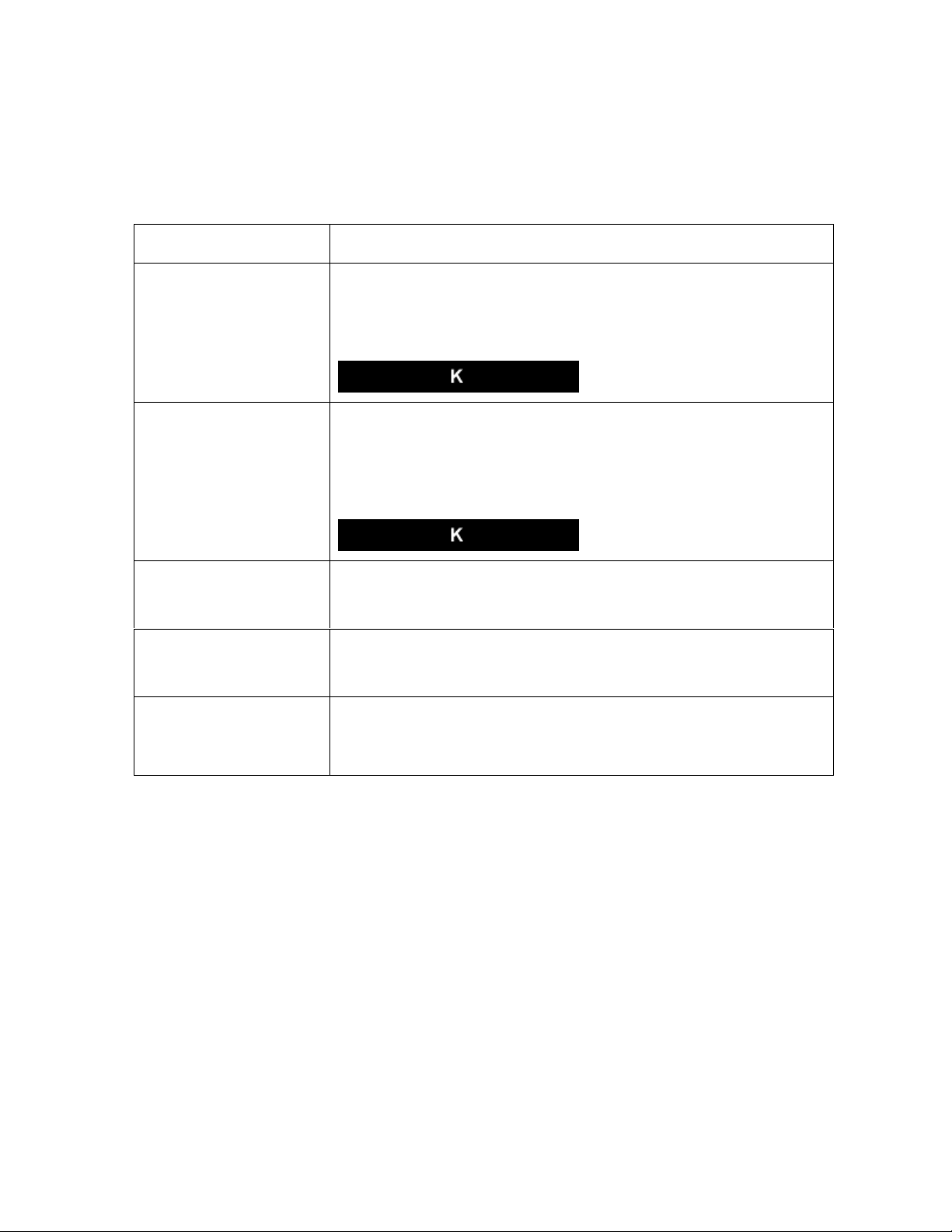
Printer Components: Resin-Only Print Ribbons
Resin-only Print Ribbons consist of a continuous roll of a single resin color. No protective
overlay panel (O) is provided since resin images do not require the protection of such an
overlay.
Type Description
Standard Resin Black
(K) (provides 1,000
prints)
Premium Resin Black
(K) (provides 1,000
prints)
Colored Resin
(provides 1,000 prints)
Metallic Resin
(provides 1,000 prints)
Scratch-Off Resin
(provides 1,000 prints)
This ribbon provides high resin durability ideal for most general
purpose monochrome ID card applications. Resin black bar
codes are readable by both infrared and visible-light bar codes
scanners.
This ribbon provides maximum resin durability ideal for
applications such as access control where cards are repeatedly
swiped through a Magnetic Stripe reader. Resin black bar codes
are readable by both infrared and visible-light bar codes
scanners.
Colored resin ribbons are available in different colors for
customizing or color coding resin-only ID cards.
Metallic resin ribbons are available for printing resin images with
a unique metallic sheen.
A scratch-off resin ribbon is available for printing over areas of a
pre-printed card in order to hide specific information such as a
personal identification number.
Pro-LX Laminating Card Printer/Encoder User Guide (Rev. 5.0) 26
Page 27

RESTRICTED USE ONLY Fargo Electronics, Inc.
Printer Components: Dye-Sublimation-Only Print Ribbons
A dye-sublimation-only Print Ribbon is available in a monochrome version. This ribbon
consists of dye-sublimation ribbon panels which alternate with a clear protective overlay (O)
panel. Dye-Sublimation images must have an overlay panel applied to them or they will
quickly begin to wear or fade.
Caution: All color or monochrome dye-sublimation images must have the ribbon's
clear overlay panel or an overlaminate applied to them. If a protective layer is not applied, the
card's dye-sublimation image will quickly begin to wear or fade. Cards printed solely with
monochrome resin text, bar codes or images do not require any type of protective overlay.
To apply the ribbon's clear overlay panel, select the Printer Driver’s Overlay / Print Area tab.
By default, the Printer Driver is setup to automatically apply the overlay panel for a selected a
ribbon type that provides an overlay (O) panel. To apply an overlaminate, select the
Lamination tab.
(Note: The Printer requires specialized Print Ribbons in order to function properly.)
Type Description
Dye-Sublimation
Black (BO)
(provides 500
prints)
Dye-Sublimationonly Print Ribbon
DyeSublimation/Resin
Print Ribbon
This ribbon provides a dye-sublimation black panel (B) along with an
overlay panel (O) and is used to print smooth, photo-quality black and
white photo ID cards. Dye-Sublimation bar codes are readable only by
visible-light bar codes scanners.
It is available in a monochrome version. This ribbon consists of dyesublimation ribbon panels which alternate with a clear protective
overlay (O) panel. Dye-Sublimation images must have an overlay panel
applied to them or they will quickly begin to wear or fade.
The Dye-Sublimation/resin Print Ribbon combines the yellow (Y),
magenta (M) and cyan (C) dye-sublimation panels with a resin black
(K) panel.
By combining both types of ribbon panels, this ribbon can be used to
print full-color, photo-quality images with the dye-sublimation panels
along with sharp, black text and bar codes with the resin black panel.
A clear overlay panel (O) is also included on most ribbons to protect the
dye-sublimation images. Dye-Sublimation images must have an overlay
panel or overlaminate applied to them or they will quickly begin to wear
or fade.
Pro-LX Laminating Card Printer/Encoder User Guide (Rev. 5.0) 27
Page 28

RESTRICTED USE ONLY Fargo Electronics, Inc.
Printer Components: Dye-Sublimation-Only Print Ribbons (continued)
Type Description
Full-Color
(YMCKO)
(provides 250
prints)
Full-Color
(YMCKOK)
(provides 250
prints)
Full-Color
(YMCKK)
(provides 250
prints)
This ribbon is used to print full-color photo ID cards along with resin black
text and bar codes. Both infrared and visible-light bar code scanners can
read bar codes printed with resin black.
An overlay panel (O) is included to protect the full-color dye-sublimation
printing.
This ribbon is used for dual-sided printing. By supplying two resin black
panels, this ribbon used to print full-color with resin black on one side and
resin black-only on the other, without wasting an entirely new set of
ribbon panels for the black-only side.
An overlay panel (O) is also included to protect the side of the card with
full-color dye-sublimation printing. No overlay is necessary for the resin
black-only side. Both infrared and visible-light bar code scanners can
read bar codes printed with resin black.
This ribbon is intended to be used for dual-sided printing. By supplying
two resin black panels, this ribbon lets you print full-color with resin black
on one side and resin black-only on the other, without wasting an entirely
new set of ribbon panels for the black-only side.
Since no overlay panel is included, this ribbon must be used in
conjunction with the Printer's overlaminate feature. No overlaminate is
necessary for the resin black-only side. Both infrared and visible-light bar
code scanners can read bar codes printed with resin black.
Pro-LX Laminating Card Printer/Encoder User Guide (Rev. 5.0) 28
Page 29

RESTRICTED USE ONLY Fargo Electronics, Inc.
Printer Components: Blank Cards
Caution: Never run cards with a contaminated, dull or uneven surface through the
Printer. Printing onto such cards will ultimately lead to poor print quality and will greatly
reduce the life of the Printhead. Always store the card stock in its original packaging or in a
clean, dust-free container. Do not print onto cards that have been dropped or soiled.
Printhead damage caused by contaminated or poor quality cards will automatically void the
Printhead's factory warranty.
Type Description
Card Size The Card Printer accepts standard CR-80 sized cards (3.375"L x 2.125"W /
85.6mmL x 54mmW) with a thickness of 30 mil (.030"/. 762mm).
Card
Design
Card
Surface
UltraCard
Stock
The Printer will print onto any card with a clean, level and polished PVC
surface.
Although the Printer is equipped with card cleaning Rollers, it is very important
to always print onto cards specifically designed for direct-to-card dyesublimation printing.
Suitable cards must have a polished PVC surface free of fingerprints, dust or
any other types of embedded contaminants. In addition, cards must have a
completely smooth, level surface in order for the Printer to achieve consistent
color coverage.
Certain types of Proximity cards have an uneven surface that will inhibit
consistent color transfer.
Certain types of smart card chips are raised slightly above the cards
surface which also results in poor color transfer.
UltraCard stock has a glossy PVC laminate on top and bottom and is optically
inspected to provide the scratch- and debris-reduced cards. Two types of
these cards are available: UltraCard and UltraCard III.
UltraCard stock has a PVC core and offers medium card durability.
UltraCard III stock has a 40% polyester core and offers high durability.
(Note: Both types of UltraCards produce printed images with a glossy, photoquality finish.)
Pro-LX Laminating Card Printer/Encoder User Guide (Rev. 5.0) 29
Page 30

RESTRICTED USE ONLY Fargo Electronics, Inc.
Printer Components: Laminator
Danger: The Printer’s Lamination Roller can reach temperatures exceeding 350
degree F (175° C). Use extreme caution when operating the Laminator. Never touch the
Lamination Roller unless the Printer Power has been turned off for at least 20 to 30 minutes.
Type Description
Controls Both the Printer itself and the Printer’s software driver control the built-in
laminator.
Temperature Upon initial power up of the Printer, the bottom line of the LCD display will
read Lam Temp = X%. (Note: This indicates that the laminator is heating
up to its preset or default laminating temperature of approximately 300° F
(150° C). The percentage number indicates how close it is to achieving
100% temperature.)
Heating
Process
Temperature
Adjustment
New
Temperature
Setting
This heating process will generally take about 3 to 4 minutes before the
laminator is heated to the default temperature. (Note: Once the laminator
reaches 100% of its default temperature, the LCD display will change to
Lam Ready.)
(Note: The LCD display will read Lam Temp = X% whenever the laminator
is heating up or cooling down to the prescribed temperature. When the
Lam Temp = 100%, the target temperature has been reached and
lamination will begin.)
To change the temperature of the laminator, adjust its temperature through
the Lamination tab within the Printer Driver setup window. (Note: Once
adjusted, the new temperature settings will be sent down with the next print
job along with the rest of the Printer Driver information.)
Before printing begins, the laminator will automatically adjust itself to the
new temperature setting. (Note: This new temperature setting will remain
programmed within the Printer until it is once again changed within the
Printer Driver or until the Printer is turned OFF.)
Whenever the Printer is turned OFF, the laminator will automatically reset
itself and return to its default temperature the next time the Printer is turned
ON.
Press the On/Cancel button to disconnect the Printer's power cord both
serve to reset the laminator to its default temperature. The temperature
setting within the Printer Driver, however, will stay the same until it is
changed.
Pro-LX Laminating Card Printer/Encoder User Guide (Rev. 5.0) 30
Page 31

RESTRICTED USE ONLY Fargo Electronics, Inc.
Reviewing the upgraded 81754 PVC Cards
The upgraded 81754 PVC cards are designed for a sharper card image quality and for
reduced debris and defects on Fargo Card Printers. Carefully read these detailed notes and
instructions before applying this information to your Fargo printer or printers.
Technician Note 1: The new card lot number starts at Lot # 2010104 with date codes
that started on 04/01/2003. The photo (below) shows a lot number that starts after Lot #
2010104, indicating a new card lot number. The card lot number and date can be read
on the bar code label attached to the shrink-wrapped stack of 100 cards, as shown
below. All new Fargo printers with a serial number (S/N) starting with A320 will have factory
settings for these new 81754 PVC cards.
Technician Note 2: Do not use the new 81754 PVC card stock with Fargo laminating
printers/encoders. This same guideline is used for the existing 81754 PVC card stock. Fargo
recommends using the UltraCard III stock with the Fargo laminating printers/encoders.
Pro-LX Laminating Card Printer/Encoder User Guide (Rev. 5.0) 31
Page 32

RESTRICTED USE ONLY Fargo Electronics, Inc.
Reviewing the upgraded 81754 PVC Cards (continued)
Follow these two (2) instructions below:
1. Instruction for new 81754 PVC card stock: Increase the Printer Driver’s Dye-Sub
Intensity to print with the new 81754 PVC card stock on Fargo Card Printers (S/N A319
and older). See the chart provided below. See the appropriate Fargo service documents
for specific Printer Driver instructions.
Card New Printer (S/N A320 and
newer)
Old Printer (S/N A319 and
older)
New Card No Change Necessary Increase the Dye-Sub Intensity as
follows:
HDP®: N/A
Pro-LX/C25: 3 - 5 %
DTC500: 5 -10 %
C11/C16: 3 - 5 %
2. Instruction for existing 81754 PVC card stock: The Printer Driver’s Dye-Sub Intensity
setting may or may not need to be decreased to print existing card stock. See the chart
provided below. See the appropriate Fargo service documents for specific Printer Driver
instructions.
Technician Note 1: To control the brightness of the image, adjust the Dye-Sub
Intensity slide on the Image Color tab of the Printer Driver.
Technician Note 2: Moving the Dye-Sub Intensity slide to the left causes less heat
to be used in the printing process, thus generating a lighter print.
Card New Printer (S/N A320 and
Old Printer (S/N A319 and older)
newer)
Old Card Decrease the Dye-Sub Intensity
No Change Necessary
as follows:
HDP®: N/A
Pro-LX/C25: 3 - 5 %
DTC500: 5 - 10 %
C11/C16: 3 - 5 %
Pro-LX Laminating Card Printer/Encoder User Guide (Rev. 5.0) 32
Page 33

RESTRICTED USE ONLY Fargo Electronics, Inc.
Printer Components: Laminator
The Printer's internal lamination system is used to choose between both a Thermal Transfer
Film overlaminate and a polyester patch overlaminate called PolyGuard™. The Thermal Film
overlaminate is a relatively thin material that covers a card edge-to-edge and provides a
medium level of ID card durability and security.
PolyGuard is a much thicker material that does not cover edge-to-edge, but provides an
extremely high level of ID card durability and security.
PolyGuard is available in either a 1.0 or .6 mil thickness and should always be used for
those applications requiring the highest degree of ID card durability and security.
PolyGuard and the Thermal Film overlaminates are available in either a clear or generic
"secure" holographic-type design. (Note: Custom holographic-type overlaminate designs
are also available with specific designs, patterns, logos and security features. Please
contact an authorized reseller for more information.)
Caution: If using the Thermal Transfer Film overlaminate, a variety of laminating
options are available within the Printer Driver. Refer to the Using the Lamination tab
description in Section 3, page 134, for complete details about these options.
Pro-LX Laminating Card Printer/Encoder User Guide (Rev. 5.0) 33
Page 34

RESTRICTED USE ONLY Fargo Electronics, Inc.
Visual Security Solutions (Specifications)
VeriMarkTM Cards - 2-D holographic foil application
VeriMarkTM Cards are a low cost, customized 2-D holographic foil application, that is made
in two steps.
The first step is to emboss a base foil 1.9 cm (L) x 1.3 cm (H) onto the surface of a blank
white card.
The second step is debossing a custom made dye into the surface of the base foil -
leaving a customized image, logo or text provided by the customer.
Two separate color foils are used to contrast the impression.
End Users will be able to choose between 8 different card placements (4 - landscape) and
(4-portrait) where the VeriMarkTM can be located. When its time to print through the driver,
the End User will select the location on their organizations card design around which no
printing and overlay will be placed.
Custom HoloMarkTM Cards
A Custom HoloMark TM Card is a three-dimensional holographic image transferred to metal
foil and embossed to blank cards. The image is customer specific and the program mirrors
our holographic laminates program with a couple exceptions.
Visual Security - Card Stock Part Numbers
All Visual Security Cards will be offered on the following Fargo Card Stocks only:
P/N# 81754 Ultra Card
P/N# 81762 Ultra Card III with hi-coercivity magnetic stripe
P/N# 81763 Ultra Card III
Visual Security - Fargo Certified Overlaminates (Special Order in 50
quantity minimum)
Part No. 82255: PolyGuard 1.0 mil for HoloMarkTM and VeriMarkTM Cards, Clear
Part No. 82256: PolyGuard 1.0 mil for HoloMarkTM and VeriMarkTM Cards, High
Resolution Globe design hologram with "Secure" micro-text
Pro-LX Laminating Card Printer/Encoder User Guide (Rev. 5.0) 34
Page 35

RESTRICTED USE ONLY Fargo Electronics, Inc.
Visual Security Card Stock - Tolerances
Tolerance of base foil placement will equal +/- .010" from the nearest edges of the card
Tolerance of layered foil will equal +/- .010"
VeriMarkTM - Application Specifications
VeriMarkTM foils will cover a dimensional area of 1.9 cm length x 1.3 cm height. The
exclusive areas are as follows:
VeriMarkTM Card customers will be able to choose 1 of 8 pre-defined placements
(corners) via printer driver (4 positions) Landscape and (4 Positions) Portrait mode.
VeriMarkTM foil placement will not interfere with card punch slots .
Foil color base is silver; debossed impression is gold foil.
VeriMarkTM foil placement will be located 0.4 cm from the edges of the card except for
the top two locations on portrait orientation cards (positions E & F). The foil will be
located 0.9 cm from the top of the card and 0.4 cm from the sides of the card.
HoloMarkTM and Custom HoloMarkTM - Application Specifications
HoloMarkTM and Custom HoloMarkTM foils will cover a dimensional area of 1.5 cm x 1.5
cm. The exclusive areas are as follows:
HoloMarkTM and Custom HoloMarkTM card end-users will be able to choose 1 of 8 pre-
defined placements (corners) via printer driver (4 positions) Landscape and (4 positions)
Portrait mode.
HoloMarkTM foil placement will not interfere with card punch slots.
Foil Color options will be silver or gold.
Outside edge placement of Foil impression options on card will be 0.4 cm from edge of
card.
HoloMarkTM foil placement options will be at all four corners of card located 0.4 cm from
edge of card.
Pro-LX Laminating Card Printer/Encoder User Guide (Rev. 5.0) 35
Page 36

RESTRICTED USE ONLY Fargo Electronics, Inc.
Section 2: General Troubleshooting
The purpose of this section is to provide the User with specific procedures relating to the
LCD/SmartGuard Messages, Communication Errors, Card Feeding Errors, Print Process
Errors, Card Jam Errors, Ribbon Errors, Encoding Errors, Diagnosing Image Problems,
Running the Self-Test and Interfacing Information for the Pro-LX Laminating Card
Printer/Encoder.
LCD/SmartGuard Messages
The LCD display shows the current status of the Printer. Refer to the cause and solution
tables in this section for all possible LCD messages. (Note: These tables display the LCD
messages in alphabetical order. If the LCD message is communicating an error or requires
an action, these tables will also offer a solution to what should be done.)
Reviewing the Top Line LCD Messages
Message Cause
Card Jam: Flip A card is jammed in the Flipper Table area of the Printer. See the
Clearing the Card Jam: Flip Error Message procedure in Section 2,
page 56.
Card Jam: Mag A card is jammed in the Mag Encoding module, beneath the Flipper
Table. See the Clearing the Card Jam: Mag Error / Smart Error
procedure in Section 2, page 54.
Card Jam: Print A card is jammed somewhere along the printing path, under the
Printer's top-right cover. See the Clearing Card Jam: Print Error
procedure in Section 2, page 53.
Card Jam: Smart A card is jammed in the smart card encoding module, beneath the
Card Flipping Mechanism. See the Clearing the Card Jam: Smart
Error procedure in Section 2, page 54.
Card Jam: Lam A card is jammed in the print station of the Printer. See the Clearing
the Card Jam: Lam Error procedure in Section 2, Page 55.
Card Out/Not Fed Either the Card Hopper is out of cards or the Printer is unable to feed
a card in from the Card Hopper. See the Clearing Card Jam Error
procedure in Section 2, page 53.
Clearing Jam Indicates error or jam is being cleared.
Feeding Card Indicates card is feeding properly.
Flipper Jam Card Flipping Mechanism is unable to rotate. See the Resolving the
Flipper Jam Error Message procedure in Section 2, page 48.
Continued on the next page
Pro-LX Laminating Card Printer/Encoder User Guide (Rev. 5.0) 36
Page 37

RESTRICTED USE ONLY Fargo Electronics, Inc.
Reviewing the Top Line LCD Messages (continued)
Message Cause
Flipping Card Indicates card is being flipped for backside printing.
Head-down Failed Printhead is unable to lower itself. See the Resolving the Headlift
Error Message procedure in Section 2, page 49.
Head-up Failed Printhead is unable to raise itself. See the Resolving the Headlift
Error Message procedure in Section 2, page 49.
Invalid Key Card The SmartGuard Access Card is invalid or is inserted backwards or
up side down. Appears only when using the SmartGuard Security
Feature. See the SmartGuard User’s Guide for more information.
Invalid Password An invalid SmartGuard password was entered. Appears only when
using the SmartGuard Security Feature. See the SmartGuard User’s
Guide for more information.
Key Card Ready Indicates SmartGuard or SmartShield data has successfully been
encoded onto the SmartGuard Access Card. Appears only when
using the SmartGuard Security Feature. See the SmartGuard User’s
Guide for more information.
Key Disabled Indicates the SmartGuard Security Feature has been disabled.
Appears only when using the SmartGuard Security Feature. See the
SmartGuard User’s Guide for more information.
Key Not Inserted Attempts are made to print without the SmartGuard Access Card
inserted. Appears only when using the SmartGuard Security
Feature. See the SmartGuard User’s Guide for more information.
Continued on the next page
Pro-LX Laminating Card Printer/Encoder User Guide (Rev. 5.0) 37
Page 38

RESTRICTED USE ONLY Fargo Electronics, Inc.
Reviewing the Top Line LCD Messages (continued)
Message Cause
Key Card Deleted Indicates the data on the SmartGuard Access Card was successfully
deleted. Appears only when using the SmartGuard Security Feature.
See the SmartGuard User’s Guide for more information.
Lam Error/Out
Error Message
Indicates a Lam Error/Out Error Message. See Resolving the Lam
Error/Out Error Message procedure in Section 2, page 57.
Low Ribbon/Clean Indicates the Print Ribbon will soon run out and that the Printer
should be cleaned.
Mag Encoding Indicates the Mag Stripe is being encoded.
Mag Verify Error The Mag Stripe was not encoded properly. See Resolving Mag
Verify Error Message Section 2, page 69.
Mag Verifying Indicates data on Mag Stripe is being verified.
No Shield Loaded Attempts are made to print with the Printer Driver's SmartShield
option selected (even though the optional SmartGuard Security
Feature is not used).
OR
If using the SmartGuard feature, the SmartShield image is not
encoded onto the SmartGuard Access Card (currently inserted into
the Printer).
See the SmartGuard User’s Guide for more information.
Print Cover Open Indicates that the top-right cover is not properly shut. If this appears
in error, see the Resolving Cover Open Error Message procedure in
Section 2, page 50.
Printer Ready Indicates the Printer is ready to print.
Printing Indicates the Printer is printing.
Continued on the next page
Pro-LX Laminating Card Printer/Encoder User Guide (Rev. 5.0) 38
Page 39

RESTRICTED USE ONLY Fargo Electronics, Inc.
Reviewing the Top Line LCD Messages (continued)
Message Cause
Rasterize Shield Indicates the Printer is loading the SmartShield security image from
the SmartGuard Access Card into its memory. Appears when a valid
access card containing a SmartShield image is first inserted into the
Printer.
(Note: If SmartShield image is named, the name will also appear
along with this message on the bottom line of the LCD Display.
Appears only when using the SmartGuard Security Feature.)
See the SmartGuard User’s Guide for more information.
Reading Key Data Indicates the Printer is reading the data from the SmartGuard
Access Card. Appears when a valid access card is first inserted into
the Printer. Appears only when using the SmartGuard Security
Feature.
See the SmartGuard User’s Guide for more information.
Rib Calib Failed
Error
Indicates that an attempt at calibrating the Ribbon Sensor through
the Printer Driver has failed. See the Resolving the Skipping Ribbon
Panel issues procedures in Section 2, page 59.
Ribbon Error/Out
Error
Indicates either the Print Ribbon is out or a ribbon error has
occurred. See Resolving Ribbon Low Error Message procedure in
Section 2, page 63.
Ribbon Jam/Out
Error
The Print Ribbon has become jammed in the Printer Rollers, it is
stuck to the surface of the card or it is out. See the Resolving the
Ribbon Breaking issues procedure in Section 2, page 64.
Ribbon Low Error
Message
Indicates either the ribbon is running low or is out. See Resolving
Ribbon Low Error Message procedure in Section 2, page 63.
Sensor Calibrate Indicates the Ribbon Sensor is calibrating. See the Resolving the
Skipping Ribbon Panel issues procedures in Section 2, page 59.
Continued on the next page
Pro-LX Laminating Card Printer/Encoder User Guide (Rev. 5.0) 39
Page 40

RESTRICTED USE ONLY Fargo Electronics, Inc.
Reviewing the Top Line LCD Messages (continued)
Message Cause
Smart Card Error Unable to encode smart card.
Smart Card Good Indicates smart card was successfully encoded.
Smart Encoding Indicates the Printer is writing or encoding data onto the SmartGuard
Access Card. Appears only when using the SmartGuard Security
Feature. See the SmartGuard User’s Guide for more information.
Writing Key Data Indicates the Printer is writing or encoding data onto the SmartGuard
Access Card. Appears only when using the SmartGuard Security
Feature. See the SmartGuard User’s Guide for more information.
Wrong Ribbon
Error
The wrong Print Ribbon is installed. See the Resolving the Wrong
Ribbon error (being displayed incorrectly) procedure in Section 2,
page 62.
Reviewing the Bottom Line LCD Error / Status Messages
Message Cause
Card Jam: Lam
Error
Clearing Jam Indicates error or jam is being cleared. See Card Jam Errors in
Lam Calib Failed An attempt at calibrating the Lamination Sensor through the Printer
Lam Cover Open The Lamination Top Cover is not properly shut. If this appears in
A card is jammed somewhere along the laminating path, under the
Printer's Lamination Top Cover. See the Resolving the Card Jam:
Lam Error procedure in Section 2, page 55.
Section 2, page 53.
Driver has failed. See the Resolving the Lam Error/Out Error
Message procedure in Section 2, page 57.
error, see the Resolving Cover Open Errors procedure in Section 2,
page 50.
Continued on the next page
Pro-LX Laminating Card Printer/Encoder User Guide (Rev. 5.0) 40
Page 41

RESTRICTED USE ONLY Fargo Electronics, Inc.
Reviewing the Bottom Line LCD Error / Status Messages (continued)
Message Cause
Lam Error/Out The overlaminate is either out or an error has occurred. See the
Resolving the Lam Error/Out Error Message procedure in Section
2, page 57.
Lam Jam/Out Error The overlaminate has either become jammed in the Printer Rollers,
stuck to the surface of the card, broken or has run out. See the
Resolving the Lam Error/Out Error Message procedure in Section
2, page 57.
Lam Ready Indicates Printer is ready to laminate. See the Using the Lamination
tab Section 3, page 134.
Lam Temp = X% Indicates the laminator is heating or cooling to its target
temperature. When the Lam Temp = 100%, the target temperature
has been reached and lamination will begin. See the Selecting the
Lamination Dwell Time and Temperature in Section 3, page 138.
Lam Turned Off Indicates laminator is OFF. The laminator can be turned off by
setting Switches 4 and 5 of the Printer's internal switches down
(towards the circuit board). See the Using the Lamination tab
Section 3, page 134.
Laminating Indicates Printer is laminating. See the Using the Lamination tab
Section 3, page 134.
Roller-dn Failed The Lamination roller is unable to lower. See the Resolving the
Headlift Error Message procedure in Section 2, page 49.
Roller-up Failed The Lamination roller is unable to rise. See the Resolving the
Headlift Error Message procedure in Section 2, page 49.
Sensor Calibrate Indicates the Lamination Sensor is calibrating. See the Using the
Lamination tab Section 3, page 134.
Wrong Lam Type
Error
The wrong overlaminate is installed. See the Resolving the Wrong
Ribbon error procedure in Section 2, page 62.
Continued on the next page
Pro-LX Laminating Card Printer/Encoder User Guide (Rev. 5.0) 41
Page 42

RESTRICTED USE ONLY Fargo Electronics, Inc.
Reviewing the BOTH Line LCD Error / Status Messages (continued)
Message Cause
CANCEL=Abort
RESUME=Continue
CANCEL=Abort
RESUME=Reprint
Delete Key Data?
RESUME=Delete
DRAM Memory
Bad!
Service Required
EE Memory Error!
RESUME=Clear
Mem
EE Memory Error!
RESUME=Retest
Appears when the Pause/Resume button is pressed any time
while the Printer is powered ON. Also appears when the
On/Cancel button is pressed during a print job.
Appears when the On/Cancel button is pressed after an error has
occurred.
Appears when deleting a SmartGuard Access Card. Appears only
when using the SmartGuard Security Feature.
The Printer's 4 MB or 16 MB memory module is bad or not installed
properly. See the Resolving the DRAM Memory Error procedure in
Section 6, page 196.
Indicates problem with permanent circuit board memory. See the
Resolving the EE Memory Error procedure in Section 6, page 195.
Permanent circuit board memory is bad. See the Resolving the EE
Checksum Error procedure in Section 6, page 195.
Insert New Key
RESUME=Duplicate
Invalid Shield
Send New Shield
Preparing Card
Count=xxxxxxxx
Press ON to
Initialize
Appears when trying to duplicate a SmartGuard Access Card.
Appears only when using the SmartGuard Security Feature.
Appears if the SmartShield data on the SmartGuard Access Card
has somehow become corrupt. Appears only when using the
SmartGuard Security Feature.
Appears when initiating a card count report from the Printer.
Appears when the On/Cancel button is pressed before a print job
is sent provided that the Printer is in its Ready mode.
Pro-LX Laminating Card Printer/Encoder User Guide (Rev. 5.0) 42
Page 43

RESTRICTED USE ONLY Fargo Electronics, Inc.
Communications Errors
Resolving the Communication Errors
Symptom(s): Incorrect output, communications error on PC or Printer, stalling, no response
from Printer, no job printed, “paper out” error.
Step Procedure
1 Confirm that the system meets the minimum requirements, as shown here:
IBM-PC or compatible
Windows 95/98/ME/NT/2000/XP Pentium™ class 133 MHz computer with
32 MB of RAM or higher
200 MB free hard disk space or higher
ECP parallel port with DMA access
2 Confirm the correct installation of the Printer Driver.
a. Close the software program and check the Printer Driver.
b. Reboot the computer.
c. Make sure the Printer Driver is installed correctly. (Note: Especially if an
obsolete driver was recently removed.)
d. Be sure the correct setup options within the Printer Driver are selected.
e. Confirm that the driver is current by checking at: www.fargo.com
3 Verify the use of an adequate data cable.
a. Use a double-shielded parallel cable (no longer than six feet in length).
(Note: Data transmission failure can be attributed to a long or faulty
parallel cable.)
b. Use a double-shielded, I-EEE 1284 compliant cable to reduce the effect of
radio emissions from computers, monitors and other equipment that may
broadcast Radio frequency interference (RFI).
Continued on the next page
Pro-LX Laminating Card Printer/Encoder User Guide (Rev. 5.0) 43
Page 44

RESTRICTED USE ONLY Fargo Electronics, Inc.
Resolving the Communication Errors (continued)
Step Procedure
4 Determine if there is interference from an external device.
a. Do not use an A/B switch box or other peripheral in line with the parallel
cable.
b. If using a switch box or other peripheral, remove it while testing
communication between the computer and the Printer.
c. If needed, replace the switch box or other peripheral (once it is determined
that the cause of the interference is not the switch box or peripheral).
d. Alternative: Add a second parallel port into the computer (if a second
Printer is required).
5 Determine the problem with printing from the application.
a. Print a self-test from the Printer as described in the Running the Self-Test
procedure in Section 2, page 87, to ensure that the Printer (itself) is
functioning properly.
b. Print the Windows test page that is located in the General tab of the driver.
c. Use WordPad (a Windows 95/ 98/ ME/ NT/ 2000/XP word processing
program in the Accessories Program Group).
Open the program and type: This is a Test.
Select File > Print on the Menu Bar.
6 Determine if the parallel port mode is set correctly or incorrectly.
a. Ensure that the parallel port is set to the Enhanced Communication Port
(ECP) mode. (Note: The port mode can be determined by checking the
Device Manager tab in the system control panel.)
b. If the port mode is not set to ECP, it will need to be changed in the
computers BIOS. (Note: Refer to the appropriate computer manual for
instructions on how to change the Parallel Port mode.)
Continued on the next page
Pro-LX Laminating Card Printer/Encoder User Guide (Rev. 5.0) 44
Page 45

RESTRICTED USE ONLY Fargo Electronics, Inc.
Resolving the Communication Errors (continued)
Step Procedure
7 Determine whether there is an adequate or inadequate hard drive space.
Caution: A large volume of temporary files on the computer can
cause communications errors.
Access the temporary files by following this process:
Search for all folders called TEMP. Once found, clear out the contents of
the folders.
If using Windows 95/98/ME/2000/XP, run the System Tool - Disk
Defragmenter found in the Accessories folder of the Start Menu.
Use a disk cleanup utility (such as Disk Cleanup found in the System
Tools folder of the Start menu) or use a third party application.
Pro-LX Laminating Card Printer/Encoder User Guide (Rev. 5.0) 45
Page 46

RESTRICTED USE ONLY Fargo Electronics, Inc.
Card Feeding Errors
Resolving the Card Feeding Errors
Symptom: Two or more cards feed at the same time or the cards will not feed at all.
Step Procedure
1 Clean the Input Roller.
a. Open the Printer's top covers and remove all cards, Print Ribbons and
overlaminate from the Printer.
b. Leave the Printer power ON and the top covers open throughout this
procedure. (Note: The card cleaning cartridge can also remain within the
Printer during this cleaning process.)
c. Use a cleaning card from the Printer Cleaning Kit and remove its adhesive
backing paper.
d. Insert the cleaning card into the card Hopper, above the card input tray, as
normally done on any other type of card.
Verify that the shortest non-adhesive end of the cleaning card enters
the Printer first and that the sticky side is facing UPWARD.
Ensure the card was not inserted with the sticky side facing downward
because then it would stick to the card input tray and not feed properly.
e. Run a self-test by following these steps.
1. Unplug power from the Printer.
2. While holding down the Pause / Resume button, reapply power.
3. Release the Pause / Resume button once the self-test has begun.
4. The cleaning card will feed into the Printer.
5. An error will be displayed when feeding the card.
6. Remove the cleaning card.
7. Reset the Printer by unplugging the power and reapplying.
Continued on the next page
Pro-LX Laminating Card Printer/Encoder User Guide (Rev. 5.0) 46
Page 47

RESTRICTED USE ONLY Fargo Electronics, Inc.
Resolving the Card Feeding Errors (continued)
Step Procedure
2 Ensure the Card Thickness Slide is set correctly.
a. Loosen the Slide Lock by rotating it counter clockwise and then push the
Card Thickness Slide forward or backward to the appropriate setting.
b. With any of the Card Thickness settings, move the slide slightly toward a
higher setting until the cards begin feeding (if the Printer seems unable to
feed cards at the selected setting).
c. Move the slide slightly toward a lower setting if the Printer seems to double-
feed cards. (Note: The card thickness slide is adjustable to accommodate
card thickness variations that often occur even within standard card sizes.)
3 Check for static build up between cards.
Occasionally, a static charge will build up between the surfaces of two or
more cards causing them to stick together.
By separating the cards manually before placing them in the input Hopper,
this static charge can be reduced or eliminated.
Pro-LX Laminating Card Printer/Encoder User Guide (Rev. 5.0) 47
Page 48

RESTRICTED USE ONLY Fargo Electronics, Inc.
Resolving the Flipper Jam Error Message
Symptom: A Flipper Jam error is displayed on the LCD.
Step Procedure
1 Check for any obstruction.
a. Open the lamination top cover. Manually rotate the Flipper Table at a full
360-degrees rotation.
b. Visually ensure that there is no obstruction in the path of the Flipper Table’s
rotation.
2 Verify the flipper clutch operation.
a. Unplug the Printer. Open the Top Lamination Cover.
b. Reapply power to the Printer. Verify that the Flipper Table rotates and
stops level with the card feed path.
3 Test the flipper home Sensor.
a. Remove the rear cover.
b. Using a digital voltmeter, connect the negative lead to its ground.
c. Connect the positive lead to Pin 2 of J8.
If blocked, the voltage should read 4.9 to 5.5 VDC.
If unblocked, the Sensor should read 0.15 to 0.18 VDC
4 Verify the motor operation.
a. Open the Top Lamination Cover.
b. Press and hold the On/Cancel Button. Verify the following:
The Rollers on the lamination side of the Printer should begin to roll.
The card feed Rollers on the card path and on the Flipper Table should
be rolling.
The platen roller and the flattener roller should be rolling.
c. Replace (as needed) the Lamination Stepper Motor if none of the Rollers
are turning. Inspect the gear configuration in the front of the Printer if any
one of the Rollers is not turning.
5 Verify the current reject Hopper capacity.
a. Open the Reject Hopper door.
b. Ensure that the card reject Hopper is not full.
Pro-LX Laminating Card Printer/Encoder User Guide (Rev. 5.0) 48
Page 49

RESTRICTED USE ONLY Fargo Electronics, Inc.
Print Process Errors
Resolving the Headlift Error Message
Symptom: The Head Up/Down Error or Roller Up/Down Error is displayed on the LCD.
Step Procedure
1 Cycle the headlift motors.
a. Remove the front cover.
b. Open both the Lamination and the Print Covers.
c. Press both buttons on the front control panel at the same time.
d. Verify that the Headlift Motors are cycling by watching the Sensor flag
rotate through the Sensor.
e. If the Motor does not turn, continue to step 2.
2 Test the headlift motors.
a. Unplug the Printer.
b. Remove the back cover.
c. Disconnect the Headlift Motor from the main board (J27 for Print Side) and
(J29 for Lam Side).
d. Connect a 9-volt battery to the Head Motor (that did not cycle).
e. If the motor does not turn, replace it.
f. If the motor does turn, continue to Step 3.
3 Test the Headlift Sensors.
a. Remove the back cover.
b. Attach the positive lead from a Digital Voltmeter to Pin 1 of J3 for print side
or Pin 1 of J4 for lamination. Attach the negative lead to the Printer Chassis
for its ground.
If unblocked, the Sensor should read 0.17 to 0.9 VDC.
If blocked, the Sensor should read 3.5 to 3.8 VDC.
c. Replace the Sensor if the voltages do not read correctly.
Pro-LX Laminating Card Printer/Encoder User Guide (Rev. 5.0) 49
Page 50

RESTRICTED USE ONLY Fargo Electronics, Inc.
Resolving the Cover Open Error Message
Symptom: A Cover Open error is displayed when the cover is closed or the Rollers do not
operate (when the cover is open).
Step Procedure
1 Test the Sensor by following these steps.
a. Remove the Rear Cover.
b. Use a Digital Voltmeter to:
Attach the negative lead to ground.
Attach the positive lead to Pin 2 of J11 to test the Print Cover Sensor
operation.
c. Connect the positive lead to Pin 2 of J12 to test the Lam Cover Sensor
operation. Replace the Sensor if the voltages are incorrect.
Verify that the voltage reads 5 VDC with the cover closed.
Verify that the voltage reads 0.12 to 0.17 VDC with the cover open.
Pro-LX Laminating Card Printer/Encoder User Guide (Rev. 5.0) 50
Page 51

RESTRICTED USE ONLY Fargo Electronics, Inc.
Resolving the Blank Output issues
Symptom: A card is ejected blank (that should be printed).
Step Procedure
1 Run a self-test.
a. Clear any card jams.
b. Unplug power from the Printer.
c. While holding down the Pause / Resume button, reapply power.
d. Release the Pause / Resume button once the Self-test has begun.
e. A self-test card will be printed.
2 Look for an image on the ribbon.
a. After a self-test has been run, open the top cover.
b. Remove the Print Ribbon from the Printer.
c. Visually inspect the set of panels that were last used by the Printer.
d. If an image is noticeable on the used ribbon, continue to step 3.
e. If an image is not noticeable on the used ribbon, continue to step 4.
3 Adjust the placement.
a. Reset the Printer to clear any Error Messages by removing the power
and reapplying it.
b. Open the Printer Control Panel from the Computer.
If using Windows 95/98/ME, right click on the Pro-LX Card Printer
Icon and select Properties.
If using Windows NT 4.0, right click on the Pro-LX Card Printer and
select Document Defaults.
If using Windows 2000/XP, right click on the Pro-LX Card Printer and
select Printing Preferences.
c. Click the Calibrate tab.
d. Click on the Settings button.
e. Adjust the Image Placement setting by +5.
f. Click on the OK button.
Continued on the next page
Pro-LX Laminating Card Printer/Encoder User Guide (Rev. 5.0) 51
Page 52

RESTRICTED USE ONLY Fargo Electronics, Inc.
Resolving the Blank Output issues (continued)
Step Procedure
4 Check the Printhead connections.
a. Open the top print cover.
b. Remove the two (2) thumbscrews from the Printhead cover plate and
remove the cover plate.
c. Check to ensure that Power and Data Cables (that connect to the
Printhead) are properly seated.
d. Remove the Back Cover.
e. Ensure that the Printhead Power Cable is properly seated on J15 on the
main board.
f. Ensure that the Printhead Data Cable is properly seated on J16 on the
main board.
5 Ensure that the proper voltage is being applied to the Printhead.
a. Remove the back cover.
b. Using a Digital Voltmeter, connect the negative lead to ground.
c. Probe Pins 1 to 5 of the Printhead power connection on J15.
d. Ensure that a voltage between 22 to 23 VDC is read on each pin.
e. If less than 22 volts is read on any of the pins, ensure that the Power
Supply for the Printer is outputting 23 to 24 VDC by testing the power
connection to the Printer with a voltmeter.
f. If the power supply is operating properly, the Main Board may need to be
replaced.
g. If 22 to 23 volts is read from Pins 1 to 5 on J15, check to ensure that the
wires from the Printhead Harness cable are in good condition and are
not pinched.
h. If the Printhead harness cable is in good condition, replace the Printhead
(as needed).
Pro-LX Laminating Card Printer/Encoder User Guide (Rev. 5.0) 52
Page 53

RESTRICTED USE ONLY Fargo Electronics, Inc.
Card Jam Errors
Resolving the Card Jam: Print Error Message
Symptoms: The card is physically jammed in the Printer or a Card Sensor is reporting a
card is present.
Step Procedure
1 Look for a jammed card in the Printer.
a. Open the Printer’s top cover.
b. Remove the ribbon from the Printer.
c. Check to see if a card is jammed in the print station of the Printer.
d. If a card is jammed in the Printer, use the Pause / Resume button and the
On / Cancel buttons to move the feed Rollers and free the card. (Note: The
card can then be fed out of the Printer.)
e. If no card was found in the print station, continue to Step 2.
2 Clean the inside of the Printer.
a. Open the Print and Lamination Top Covers.
b. Use a can of deionized to blow any dirt or debris from the Printer.
2 Test the Card Feed Detection Sensor.
a. Remove the rear cover.
b. Using a Digital voltmeter, connect the negative lead to ground.
c. Connect the positive lead to Pin 1 of J6.
If blocked, the voltage should read 4.9 to 5.5 VDC.
If unblocked, the Sensor should read 0.15 to 0.18 VDC.
d. If the voltages do not read correctly, replace the Sensor.
3 Test the TOF Sensor.
a. Remove the rear cover.
b. Using a Digital voltmeter, connect the negative lead to ground. Connect the
positive lead to Pin 1 of J5.
If blocked, the voltage should read 4.9 to 5.5 VDC.
If unblocked, the Sensor should read 0.15 to 0.18 VDC.
c. If the voltages do not read correctly, replace the Sensor.
Pro-LX Laminating Card Printer/Encoder User Guide (Rev. 5.0) 53
Page 54

RESTRICTED USE ONLY Fargo Electronics, Inc.
Resolving the Card Jam: Mag Error / Smart Error Message
Symptoms: The Card Jam: Mag Error or Card Jam: Smart Error is displayed on the LCD.
Step Procedure
1 Look for a jammed card in the Printer.
a. Open the Printer’s top cover.
b. Remove the ribbon from the Printer.
c. Check to see if a card is jammed in the print station of the Printer.
d. If a card is jammed in the Printer, use the Pause / Resume button and the
On / Cancel buttons to move the feed Rollers and free the card. (Note: The
card can then be fed out of the Printer.)
e. If no card was found in the print station, continue to Step 2.
2 Check the Magnetic Offset Setting.
a. Reset the Printer to clear any Error Messages by removing the power and
reapplying it.
b. Open the Printer Control Panel from the Computer.
If using Windows 95/98/ME, right click on the Pro-LX Card Printer Icon
and select Properties.
If using Windows NT 4.0, right click on the Pro-LX Card Printer and select
Document Defaults.
If using Windows 2000/XP, right click on the Pro-LX Card Printer and
select Printing Preferences.
c. Click the Calibrate tab.
d. Click on the Settings button.
e. Ensure that the Magnetic Offset setting matches the value (that is written on
the back of the Printer).
3 Test the Card Detection Sensor.
a. Remove the rear cover.
b. Using a Digital voltmeter, connect the negative lead to ground. Connect the
positive lead to Pin 1 of J31.
If blocked, the voltage should read 3.8 to 3.5 VDC.
If unblocked, the Sensor should read 0.15 to 0.18 VDC.
c. If the voltages do not read correctly, replace the Sensor.
Pro-LX Laminating Card Printer/Encoder User Guide (Rev. 5.0) 54
Page 55

RESTRICTED USE ONLY Fargo Electronics, Inc.
Resolving the Card Jam: Lam Error Message
Symptom: The Card Jam: Lam Error is displayed on the LCD.
Step Procedure
1 Look for a jammed card in the Printer.
a. Open the Printer’s top cover.
b. Remove the ribbon from the Printer.
c. Check to see if a card is jammed in the Lam Station of the Printer.
d. If a card is jammed in the Printer, use the Pause / Resume button and the
On / Cancel buttons to move the feed Rollers and free the card. (Note: The
card can then be fed out of the Printer.)
e. If no card was found in the Lam Station, continue to Step 2.
2
Test the TOF Sensor. (Note: If the Printer has begun laminating the card and
then jams, it may be possible that the centering of the lamination of the card has
caused the jam.)
a. Inspect the card and determine if the lamination is centered on the card.
b. If the Lamination is hanging off the leading or trailing edge of the card, see
Using the Lamination Placement option procedure in Section 3, page 105.
3 Test the Card Detection Sensor.
a. Remove the rear cover.
b. Using a Digital voltmeter, connect the negative lead to ground.
c. Connect the positive lead to Pin 1 of J6.
If blocked, the voltage should read 4.9 to 5.5 VDC.
If unblocked, the Sensor should read 0.15 to 0.18 VDC.
d. If the voltages do not read correctly, replace the Sensor.
Pro-LX Laminating Card Printer/Encoder User Guide (Rev. 5.0) 55
Page 56

RESTRICTED USE ONLY Fargo Electronics, Inc.
Resolving the Card Jam: Flip Error Message
Symptom: A Card Jam: Flip Error is displayed on the LCD.
Step Procedure
1 Run a Self test.
a. Clear any card jams.
b. Unplug power from the Printer.
c. While holding down the Pause / Resume button, reapply power.
d. Release the Pause / Resume button once the self-test has begun.
(Note: A test card will be printed.)
e. If successful, this will ensure proper flipper operation on a simple double-
sided print.
2 Check the Flipper Offset.
a. Clear any card jams.
b. Open the top covers.
c. Unplug power from the Printer and reapply. (Note: The Flipper Table
will cycle on startup.)
d. When finished, the Flipper Table should be completely level with the
card feed path. If it is not, adjust the flipper offset (as needed).
3
Check for warpage. (Note: When laminating both sides of the card, the
card is subjected to excessive amounts of heat. This can cause the card to
warp significantly, depending on the composition of the card.)
a. Print a card that is only laminated on one side.
b. Once the card is ejected, lay the card on a flat surface.
c. Ensure that the warpage amount is less than 30 mil.
d. Slide a standard, 30-mil card under the laminated card. If there is
substantial clearance, see Adjusting the Card Flattener in Section 3, on
page 107.
Pro-LX Laminating Card Printer/Encoder User Guide (Rev. 5.0) 56
Page 57

RESTRICTED USE ONLY Fargo Electronics, Inc.
Ribbon Errors
Resolving the Lam Error/Out Error Message
Symptom: The Printer seems to skip PolyGuard overlaminate patches or simply wind the
overlaminate until the Printer's Ready LED flashes.
Step Procedure
1 Check that the proper Over-Laminate type is installed according to the
Lamination Type option selected in the Printer Driver.
a. Open the Printer control panel from the Computer.
If using Windows 95/98/ME, right click on the Pro-LX Card Printer
Icon and select Properties.
If using Windows NT 4.0, right click on the Pro-LX Card Printer and
select Document Defaults.
If using Windows 2000/XP, right click on the Pro-LX Card Printer and
select Printing Preferences.
b. Click on the Lamination tab.
c. Ensure that the Lamination Type (selected) matches the Lamination type
installed in the Printer.
2 Calibrate the Lamination Sensor.
a. Reset the Printer to clear any Error Messages by removing Power and
reapplying it.
b. Open the Printer control panel from the Computer.
If using Windows 95/98/ME, right click on the Pro-LX Card Printer
Icon and select Properties.
If using Windows NT 4.0, right click on the Pro-LX Card Printer and
select Document Defaults.
If using Windows 2000/XP, right click on the Pro-LX Card Printer and
select Printing Preferences.
c. Click the Calibrate tab.
d. Click on the Sensors button.
e. Remove the Laminate ribbon and close the top cover.
f. Click on the Send button for a Lamination Sensor Calibration.
Continued on the next page
Pro-LX Laminating Card Printer/Encoder User Guide (Rev. 5.0) 57
Page 58

RESTRICTED USE ONLY Fargo Electronics, Inc.
Resolving the Lam Error/Out Error Message (continued)
Step Procedure
3 Check the Laminate Ribbon Clutch to determine if it is too loose.
a. Remove the back cover.
b. Use a 7/16” wrench to tighten the nut on the end of the encoder wheel by
½ - turn.
4 Test the Encoder Sensor.
a. Remove the back cover.
b. Using a Digital voltmeter, connect the negative lead to ground.
c. Connect the positive lead to Pin 4 of J13.
If blocked, the voltage should read 4.9 to 5.5 VDC.
If unblocked, the Sensor should read 0.15 to 0.18 VDC.
d. If the voltages do not read correctly the Sensor should be replaced.
Pro-LX Laminating Card Printer/Encoder User Guide (Rev. 5.0) 58
Page 59

RESTRICTED USE ONLY Fargo Electronics, Inc.
Resolving the Skipping Ribbon Panel issues
Symptom: The Printer is using more than one set of ribbon panels to print one side of a
card.
Step Procedure
1 Calibrate the Ribbon Sensor.
a. Reset the Printer to clear any Error Messages by removing Power and
reapplying.
b. Open the Printer Control Panel from the Computer.
If using Windows 95/98/ME, right click on the Pro-LX Card Printer
Icon and select Properties.
If using Windows NT 4.0, right click on the Pro-LX Card Printer and
select Document Defaults.
If using Windows 2000/XP, right click on the Pro-LX Card Printer and
select Printing Preferences. Click on the Calibrate tab.
c. Click on the Sensors button.
d. Remove the ribbon and close the top cover.
e. Click on the Send button for a Ribbon Sensor calibration.
Verify that the Printer beeps twice and the LCD displays Sensor Calibrate.
Continued on the next page
Pro-LX Laminating Card Printer/Encoder User Guide (Rev. 5.0) 59
Page 60

RESTRICTED USE ONLY Fargo Electronics, Inc.
Resolving the Skipping Ribbon Panel issues (continued)
Refer to the previous procedure.
Continued on the next page
Pro-LX Laminating Card Printer/Encoder User Guide (Rev. 5.0) 60
Page 61

RESTRICTED USE ONLY Fargo Electronics, Inc.
Resolving the Skipping Ribbon Panel issues (continued)
Step Procedure
2 Adjust the Ribbon Clutch
a. Remove the back cover.
b. Use a 7/16th wrench to tighten the nut on the end of the encoder wheel
by a ½ - turn.
3 Test the Encoder Sensor.
a. Remove the back cover.
b. Using a Digital Voltmeter, connect the negative lead to ground.
c. Connect the positive lead to Pin 4 of J13.
If blocked, the voltage should read 4.9 to 5.5 volts DC.
If unblocked, the Sensor should read 0.15 to 0.18 volts DC.
Pro-LX Laminating Card Printer/Encoder User Guide (Rev. 5.0) 61
Page 62

RESTRICTED USE ONLY Fargo Electronics, Inc.
Resolving the Wrong Ribbon error (being displayed incorrectly)
Symptom: A Wrong Ribbon Error is displayed on the LCD even though the correct ribbon is
installed in the Printer.
Step Procedure
1 Verify the driver settings are correct.
a. Open the Printer Control Panel from the Computer.
If using Windows 95/98/ME, right click on the Pro-LX Card Printer
Icon and select Properties.
If using Windows NT 4.0, right click on the Pro-LX Card Printer and
select Document Defaults.
If using Windows 2000/XP, right click on the Pro-LX Card Printer and
select Printing Preferences.
b. Click on the Device Options tab.
c. Ensure that the Ribbon Type setting that is listed matches the ribbon that
is installed in the Printer. (Note: It may be possible to have driver
settings that are different from those found in the Printer control panel
through the software.)
d. Check any page setup functions in the software to ensure that the
Ribbon type matches.
Continued on the next page
Pro-LX Laminating Card Printer/Encoder User Guide (Rev. 5.0) 62
Page 63

RESTRICTED USE ONLY Fargo Electronics, Inc.
Resolving the Wrong Ribbon error (being displayed incorrectly) (continued)
Step Procedure
2 Test the Ribbon ID Sensor.
a. Unplug the Printer.
b. Remove the back cover.
c. Flip switches 3 and 4 on the bank of DIP switches in the Main Board
corner.
d. With the top covers closed, apply power to the Printer while holding down
the Pause/Resume button.
e. Once the LCD screen displays RUNNING SELF TEST #12, release the
Pause/Resume Button.
f. Open up the top Print cover.
g. Slowly rotate the supply side of the ribbon. (Note: As the spool is rolling,
the Printer should emit a beep every time a metal pin from the ribbon ID
core passes the Sensor.)
h. Replace the Ribbon ID Sensor if the Printer responds by emitting no
beeps or if one long set of beeps is emitted (regardless of the ribbon’s
position).
Resolving the Ribbon Low Message
Symptoms: The Printer beeps just before each ribbon panel is printed. The ribbon is
running low, which indicates the Print Ribbon is running low and that it will soon run out.
When this message is displayed, there should be 10 to 20 additional prints left on the ribbon.
Step Procedure
1 Print until the ribbon is gone and replace the ribbon as needed.
Pro-LX Laminating Card Printer/Encoder User Guide (Rev. 5.0) 63
Page 64

RESTRICTED USE ONLY Fargo Electronics, Inc.
Resolving the Ribbon Breaking issues
Symptom: The Ribbon breaks when printing or a Ribbon Jam Error is displayed on the LCD
Step Procedure
1 Calibrate the Ribbon Sensor.
a. Reset the Printer to clear any Error Messages by removing Power and
reapplying.
b. From the Computer, open the Printer control panel.
If using Windows 95/98/ME, right click on the Pro-LX Card Printer
Icon and select Properties.
If using Windows NT 4.0, right click on the Pro-LX Card Printer and
select Document Defaults.
If using Windows 2000/XP, right click on the Pro-LX Card Printer and
select Printing Preferences.
c. Click the Calibrate tab.
d. Click on the Sensors button.
e. Remove the Ribbon and close the top cover.
f. Click on the Send button for a Ribbon Sensor Calibration.
Continued on the next page
Pro-LX Laminating Card Printer/Encoder User Guide (Rev. 5.0) 64
Page 65

RESTRICTED USE ONLY Fargo Electronics, Inc.
Resolving the Ribbon Breaking issues (continued)
Step Procedure
2 Determine where the ribbon is breaking.
a. Open the Top Print Cover.
b. Remove the ribbon from the Printer.
c. Inspect the ribbon at the break point.
If the Ribbon broke before any print was applied to the card, continue
to Step 3.
If the Ribbon broke after applying the print to the card, continue to
Step 4.
3 Adjust the Image Placement.
a. Reset the Printer to clear any Error Messages by removing Power and
reapplying.
b. Open the Printer Control Panel from the Computer.
If using Windows 95/98/ME, right click on the Pro-LX Card Printer
Icon and select Properties.
If using Windows NT 4.0, right click on the Pro-LX Card Printer and
select Document Defaults.
If using Windows 2000/XP, right click on the Pro-LX Card Printer and
select Printing Preferences.
c. Click the Calibrate tab.
d. Click on the Settings button.
e. Adjust the Image Placement setting by +10.
f. Click on OK.
g. Print a Self-Test.
h. After adjusting the Image Placement, if a white edge appears on the card,
adjust the image placement back toward its original value in increments
of 2 until the white edge is gone.
Continued on the next page
Pro-LX Laminating Card Printer/Encoder User Guide (Rev. 5.0) 65
Page 66

RESTRICTED USE ONLY Fargo Electronics, Inc.
Resolving the Ribbon Breaking issues (continued)
Step Procedure
4 Adjust the Image Placement.
a. Reset the Printer to clear any Error Messages by removing Power and
reapplying.
b. Open the Printer Control Panel from the Computer.
If using Windows 95/98/ME, right click on the Pro-LX Card Printer Icon
and select Properties.
If using Windows NT 4.0, right click on the Pro-LX Card Printer and select
Document Defaults.
If using Windows 2000/XP, right click on the Pro-LX Card Printer and
select Printing Preferences.
c. Click the Calibrate tab.
d. Click on the Settings button.
e. Adjust the Image Placement setting by -10.
f. Click on OK.
g. Print a Self-Test.
h. After adjusting the Image Placement, if a white edge appears on the card,
adjust the image placement back toward its original value in increments of 2
until the white edge is gone.
Pro-LX Laminating Card Printer/Encoder User Guide (Rev. 5.0) 66
Page 67

RESTRICTED USE ONLY Fargo Electronics, Inc.
Resolving the Lamination (not adhering to the card surface)
problem
Symptom: The lamination will not transfer to the card or is easily peeled off the card.
Step Procedure
1 Ensure the Card quality by verifying that these requirements are met:
a. Requirement 1: That the Printer does print onto any card with a clean,
level and polished PVC surface. (Note: Although the Printer is equipped
with card cleaning Rollers, it is very important to always print onto cards
specifically designed for direct-to-card dye-sublimation printing to ensure
proper print quality.)
b. Requirement 2: That suitable cards display a polished PVC surface
free of fingerprints, dust or any other types of embedded contaminants.
(Note: In addition, cards must have a completely smooth, level surface
in order for the Printer to achieve consistent color coverage.)
c. Requirement 3: That certain types of Proximity cards with an uneven
surface (which can inhibit consistent color transfer) are identified. (Note:
Likewise, some smart card chips are raised slightly above the cards
surface, which also results in poor color transfer.)
d. Recommendation: That high-quality blank cards (e.g., a factory-
approved card stock called UltraCard™ are in use.
UltraCard stock has a glossy PVC laminate on top and bottom and is
optically inspected to provide the cleanest, most scratch and debris-
reduced cards possible.
UltraCard stock, which has a PVC core and offers medium card
durability. UltraCard III stock has a 40% polyester core and offers
high durability.
Both types of UltraCards produce printed images with a glossy,
photo-quality finish. For the flattest possible cards when laminating, it
is recommended use of UltraCard III card stock.)
Continued on the next page
Pro-LX Laminating Card Printer/Encoder User Guide (Rev. 5.0) 67
Page 68

RESTRICTED USE ONLY Fargo Electronics, Inc.
Resolving the lamination (not adhering to the card surface) problem (cont.)
Step Procedure
2 Check Lamination Temperature.
a. Open the Printer Control Panel from the Computer.
If using Windows 95/98/ME, right click on the Pro-LX Card Printer
Icon and select Properties.
If using Windows NT 4.0, right click on the Pro-LX Card Printer and
select Document Defaults.
If using Windows 2000/XP, right click on the Pro-LX Card Printer and
select Printing Preferences.
b. Click on the Lamination tab.
c. Increase the Lamination Temperature by +5 degrees.
d. Click on the OK button.
e. Print and Laminate a card from the software.
f. Continue to adjust the Lamination Temperature until the lamination
adheres completely and cannot be peeled off.
g. Adjust (as needed) the card flattener if increased temperature is causing
the cards to bow.
Pro-LX Laminating Card Printer/Encoder User Guide (Rev. 5.0) 68
Page 69

RESTRICTED USE ONLY Fargo Electronics, Inc.
Encoding Errors
Resolving the Mag Verify Error Message
Symptoms: A Mag Verify error is displayed on the LCD when attempting to encode.
Step Procedure
1 Check to ensure that the cards are loaded with the Magnetic Stripe facing down
and towards the back of the Printer.
2 Verify the Driver settings if cards are loaded properly. Properly loaded cards will
be oriented with the mag stripe facing down and toward the back of the Printer.
See the Using the Magnetic Encoding tab procedure in Section 3, page 118.
3 Verify that data is being encoded to the Magnetic Stripe.
a. Clear any Error Messages from the LCD by unplugging the Printer and
reapplying power.
b. Remove the failed card from the Reject Hopper.
c. Use a Magnetic Stripe reader or magnetic developer spray to determine if
data is being written to the Magnetic Stripe.
If data is not being written to the Magnetic Stripe, remove the back cover
and verify that the magnetic head is plugged into J100 on the main
board.
If the Magnetic head connection is properly seated, replace the magnetic
head (as needed). See the Replacing the Mag Head procedure in
Section 5, page Error! Bookmark not defined..
If data is being written to the Magnetic Stripe, adjust the Mag TOF (as
needed). Refer to the Mag TOF display on the next page. . See the Using
the Magnetic Offset option procedure in Section 3, page 103.
Continued on the next page
Pro-LX Laminating Card Printer/Encoder User Guide (Rev. 5.0) 69
Page 70

RESTRICTED USE ONLY Fargo Electronics, Inc.
Magnetic Head
(3 Stationary
Direction of Card
0.293 inches (nul characters)
Magnetic Head
Sensor
Resolving the Mag Verify Error Message (Continued)
Refer to the previous procedure regarding this display.
Start Sentinel
Position
Magnetic Tracks)
Travel while being
Magnetically Encoded
Encoding
Module
Card
Feed Path
Card Feed
Roller
e
h
t
t
e
a
h
t
d
f
r
o
a
s
c
g
a
n
0
p
i
8
-
n
g
n
n
R
i
i
C
g
d
e
o
b
c
n
e
Flipper
Table
Flip
.
s
Card Sensor
Pro-LX Laminating Card Printer/Encoder User Guide (Rev. 5.0) 70
Page 71

RESTRICTED USE ONLY Fargo Electronics, Inc.
Determining why the Printer cannot read encoded data
Step Procedure
1 Verify that the cards are loaded properly with the Magnetic Stripe facing down
and towards the back of the Printer.
2 Verify that the card is encoded with magnetic data by using a Magnetic Imager
or Developer Solution.
3
Use WordPad (a Windows 95/ 98/ ME/ NT/ 2000/XP word processing program
in the Accessories Program Group).
a. Go to the File menu and select Page Setup.
b. Click on the Printer button and select the Pro-LX Card Printer.
c. Click OK and reset all four margins to zero. (Note: The WordPad will
automatically replace the values with it’s minimum margins.)
d. Open the program and type: “~1%JULIEANDERSON^1234567890?” then,
go to File on the menu bar and select Print. (Note: The Printer should then
feed a card into the Encoder and magnetically encode it.)
4 Check the Magnetic Offset Setting.
a. Reset the Printer to clear any Error Messages by removing the power and
reapplying it.
b. Open the Printer Control Panel from the Computer.
If using Windows 95/98/ME, right click on the Pro-LX Card Printer Icon
and select Properties.
If using Windows NT 4.0, right click on the Pro-LX Card Printer and select
Document Defaults.
If using Windows 2000/XP, right click on the Pro-LX Card Printer and
select Printing Preferences.
c. Click the Calibrate tab.
d. Click on the Settings button.
e. Ensure that the Magnetic Offset setting matches the value that is written on
the back of the Printer.
5 Verify that the coercivity of the cards matches the setting in the Driver.
6 Compare the settings for the Card Reader to the settings in the Driver.
7 Verify that the Magnetic Stripe on the card is free of scratches or voids.
Pro-LX Laminating Card Printer/Encoder User Guide (Rev. 5.0) 71
Page 72

RESTRICTED USE ONLY Fargo Electronics, Inc.
Resolving data intended for the Magnetic Stripe (being printed on
the card) problem
Step Procedure
1 Confirm that the application is formatting the magnetic string correctly. See the
Using the Magnetic Track Selection option procedure in Section 3, page 121.
2
a. Use WordPad (a Windows 95/ 98/ ME/ NT/ 2000/XP word processing
program in the Accessories Program Group).
b. Go to the File menu and select Page Setup.
c. Click on the Printer button and select the Pro-LX Card Printer.
d. Click OK and reset all four margins to zero.
(Note: WordPad will automatically replace the values with it’s minimum margins.)
e. Open the program and type: “~1%JULIEANDERSON^1234567890?” then,
go to File on the menu bar and select Print. (Note: The Printer should then
feed a card into the Encoder and magnetically encode it.)
Pro-LX Laminating Card Printer/Encoder User Guide (Rev. 5.0) 72
Page 73

RESTRICTED USE ONLY Fargo Electronics, Inc.
Diagnosing Image Problems
Resolving the Pixel Failure problems
Symptom: A thin line or scratch travels the entire length of the card.
Step Procedure
1 Check the card stock for scratches. Replace the cards (as needed).
2 Examine the Printhead for visible damage.
3 Clean the Printhead. See Cleaning the Printhead procedure in Section 4, page
186.
4 Replace the Cleaning Tape. See Replacing the Cleaning Tape procedure in
Section 4, page 189.
5 Clean the Platen Rollers. See Cleaning the Platen Rollers procedure in Section
4, page 191.
6 Replace the Printhead if the problem persists. See Replacing the Printhead
procedure in Section 5, page Error! Bookmark not defined..
Pro-LX Laminating Card Printer/Encoder User Guide (Rev. 5.0) 73
Page 74

RESTRICTED USE ONLY Fargo Electronics, Inc.
Resolving the Card Surface Debris problems
Symptom: Prints have spots (white or colored voids) and/or dust on them.
Step Procedure
1 Be sure the cards are clean and stored in a dust-free environment. Do not use
cards with embedded contaminants in the surface.
2 Clean the inside of the Printer. See Cleaning the Printer’s Interior procedure in
Section 4, page 192.
3 Replace the Cleaning Tape. See Replacing the Cleaning Tape procedure in
Section 4, page 189.
4 Clean the Platen Rollers. See Cleaning the Platen Rollers procedure in Section
4, page 191.
Pro-LX Laminating Card Printer/Encoder User Guide (Rev. 5.0) 74
Page 75

RESTRICTED USE ONLY Fargo Electronics, Inc.
Resolving the Incorrect Image Darkness problems
Symptom: Printed cards are too dark or too light.
Step Procedure
1 Run a self-test to identify problems with the driver settings. See Running the Self
Test in Section 2, page 87.
2
Adjust the Dye-Sub Intensity setting within the Image Color tab of the Printer
Driver. See Using the Image Color tab procedure in Section 3, page 157.
Continued on the next page
Pro-LX Laminating Card Printer/Encoder User Guide (Rev. 5.0) 75
Page 76

RESTRICTED USE ONLY Fargo Electronics, Inc.
Resolving the Incorrect Image Darkness problems (continued)
Step Procedure
3
Correct the Image Darkness. See Using the Image Darkness option in Section
3, page 100.
Pro-LX Laminating Card Printer/Encoder User Guide (Rev. 5.0) 76
Page 77

RESTRICTED USE ONLY Fargo Electronics, Inc.
Resolving the Ribbon Wrinkle problems
Symptom: Printed cards have off-colored lines or streaks on them.
Step Procedure
1 Confirm that the Printer is using the most current driver via: http://www.fargo.com
2
Reduce the Dye-Sub Intensity setting within the Image Color tab of the Printer
Driver. See Using the Image Color tab procedure in Section 3, page 157.
Continued on the next page
Pro-LX Laminating Card Printer/Encoder User Guide (Rev. 5.0) 77
Page 78

RESTRICTED USE ONLY Fargo Electronics, Inc.
Resolving the Ribbon Wrinkle problems (continued)
Step Procedure
3 Reduce the Image Darkness. See Using the Image Darkness option in Section
3, page 100.
4 Increase the Ribbon tension.
a. Unplug the Printer.
b. Remove the rear cover.
c. Use a 7/16th wrench to tighten the nut on the Ribbon Encoder ½ - turn.
d. Reapply power.
e. Print a card.
If the wrinkle effect is gone, continue printing.
If the wrinkle effect is diminished, continue tightening the Ribbon Encoder
nut, in ¼ - turn increments until the wrinkle is gone.
Pro-LX Laminating Card Printer/Encoder User Guide (Rev. 5.0) 78
Page 79

RESTRICTED USE ONLY Fargo Electronics, Inc.
Resolving the Excessive Resin Printing problems
Symptom: Black resin text and barcodes appear smeared or too thick.
Step Procedure
1 Reduce the Resin Heat setting within the Image Color tab of the Printer Driver.
See Using the Image Color tab procedure in Section 3, page 157.
Continued on the next page
Pro-LX Laminating Card Printer/Encoder User Guide (Rev. 5.0) 79
Page 80

RESTRICTED USE ONLY Fargo Electronics, Inc.
Resolving the Excessive Resin Printing problems (continued)
Step Procedure
2 Reduce the Image Darkness. See Using the Image Darkness option in Section 3,
page 100.
Pro-LX Laminating Card Printer/Encoder User Guide (Rev. 5.0) 80
Page 81

RESTRICTED USE ONLY Fargo Electronics, Inc.
Resolving the Incomplete Resin Printing problems
Symptom: Black resin text and barcodes appear faded or too light.
Step Procedure
1
Increase the Resin Heat setting within the Image Color tab of the Printer
Driver. See Using the Image Color tab procedure in Section 3, page 157.
2
Increase the Image Darkness. See Using the Image Darkness option in
Section 3, page 100.
Pro-LX Laminating Card Printer/Encoder User Guide (Rev. 5.0) 81
Page 82

RESTRICTED USE ONLY Fargo Electronics, Inc.
Resolving the Image Placement problems
Symptom: Printing is cut off or is not centered on the card or a white border appears.
Step Procedure
1 Verify if the Image Position option within the Calibrate tab is set incorrectly.
a. Open the Printer Control Panel from the Computer.
If using Windows 95/98/ME, right click on the Pro-LX Card Printer Icon
and select Properties.
If using Windows NT 4.0, right click on the Pro-LX Card Printer and select
Document Defaults.
If using Windows 2000/XP, right click on the Pro-LX Card Printer and
select Printing Preferences.
b. Click on the Calibrate tab.
c. Adjust the Vertical and/or Horizontal Image Position settings based on
where the white border is on the card.
Continued on the next page
Pro-LX Laminating Card Printer/Encoder User Guide (Rev. 5.0) 82
Page 83

RESTRICTED USE ONLY Fargo Electronics, Inc.
Resolving the Image Placement problems (continued)
Refer to the previous procedure.
Pro-LX Laminating Card Printer/Encoder User Guide (Rev. 5.0) 83
Page 84

RESTRICTED USE ONLY Fargo Electronics, Inc.
Resolving the Image Placement problems (continued)
Step Procedure
2
Verify the Image Placement setting is set correctly.
a. Open the Printer Control Panel from the Computer.
If using Windows 95/98/ME, right click on the Pro-LX Card Printer Icon
and select Properties.
If using Windows NT 4.0 right click on the Pro-LX Card Printer and select
Document Defaults.
If using Windows 2000/XP, right click on the Pro-LX Card Printer and
select Printing Preferences.
b. Click on the Calibrate tab.
c. Click on the Settings button.
If the white border is on the leading edge of the card, adjust the Image
Placement value by –2.
If the white border is on the trailing edge of the card, adjust the Image
Placement value by +2.
d. Click on OK.
e. Run a self-test.
f. If the white border is diminished, continue the adjustment until it is gone.
3 Adjust the Card Guide Bar as needed.
a. Open the Top Print Cover.
b. Loosen the two screws that hold the Card Guide Bar in Place.
c. Remove the back cover.
d. Locate the Card Guide adjustment screws.
If the white border is on the side of the card closest to the front side plate,
turn both Card Guide Adjustment Screws clockwise ¼ - turn.
If the white border is on the side of the card closest to the backside plate,
turn both Card Guide Adjustment Screws counter-clockwise ¼ - turn.
Pro-LX Laminating Card Printer/Encoder User Guide (Rev. 5.0) 84
Page 85

RESTRICTED USE ONLY Fargo Electronics, Inc.
Resolving the Image Placement problems (continued)
Refer to the previous procedure.
Pro-LX Laminating Card Printer/Encoder User Guide (Rev. 5.0) 85
Page 86

RESTRICTED USE ONLY Fargo Electronics, Inc.
Resolving the Poor Image Quality problems
Symptom: Photos on the cards look pixilated or grainy, as shown below.
Step Procedure
1 Use high-resolution, 24-bit color images to capture an image:
at a 24-bit color setting,
at 300 dpi and
at the same size (that it will be printed on the card, as captured either with a
scanner or with a digital camera).
Caution: If a small or low-resolution image is stretched or "blown up",
a pixilated or grainy effect will occur when printing, as shown below (right side).
Pro-LX Laminating Card Printer/Encoder User Guide (Rev. 5.0) 86
Page 87

RESTRICTED USE ONLY Fargo Electronics, Inc.
Running the Self Test
Perform a self-test after (a) an initial setup of the Printer, (b) a calibration procedure has
been conducted or (c) a part has been replaced to check for proper Printer operation.
Step Procedure
1 Verify that a full-color ribbon is installed and that cards are properly loaded.
Caution: If the power is ON, disconnect the Power Cable from the
Printer’s rear panel.
2
3
4
Press and hold the Pause/Resume button.
While holding down the Pause/Resume button, plug the power cable back into the
Printer.
Once the On LED illuminates, release the button.
The Flipper Table will re-align itself.
The Printer will print a 3-color process gray scale on the front, flip the card and
print the monochrome black panel on the back. The overlay pass is not printed
during the Self-test.
The card will be ejected with the backside face up.
Reverse the card to look at the front side and examine the gray scale pattern with
the green bar at the top and a red bar at the bottom of the card.
Running the Standard Self Test Print
This card will be printed.
PRO-LX
Pro-LX Laminating Card Printer/Encoder User Guide (Rev. 5.0) 87
Page 88

RESTRICTED USE ONLY Fargo Electronics, Inc.
Reviewing the Main Circuit Board
Perform the standard self-test and the other test modes (made available by changing the DIP
Switch Settings within the Printer). Use these additional self-tests to isolate and diagnose
Printer problems and test for proper Printer operation after Printer calibration. (Note: The
Main Circuit Board (below) displays the location of the DIP switches and how to activate
them.)
Step Procedure
1 To remove the rear cover to expose the Main Circuit Board. See Removing the
Main Board in Section 5, page Error! Bookmark not defined..
2 To find the DIP switches on the Main Circuit Board, see the figure (below).
3 To activate the DIP switches, see the Setting the DIP Switch Settings in
Section 2, page 91.
Pro-LX Laminating Card Printer/Encoder User Guide (Rev. 5.0) 88
Page 89

RESTRICTED USE ONLY Fargo Electronics, Inc.
6
6
7
7
8
8
Using the DIP Switch (Self-test)
Step Procedure
1 Activate any of these diagnostic tests and Calibration modes. See Running the
Self Test in Section 2, page 87. During the activation of the Self-test, the Printer
will:
Detect the change to the DIP Switch Settings. See Using the DIP Switch Self
Test in Section 2, page 89.
Operate the Printer in that selected Test or Calibration mode.
2 Return all the DIP switches back to their normal OFF position once the tests are
completed.
3 Leave the associated DIP switches activated to operate the Printer this way or
temporarily use the settings to test a particular Printer operation. (Note: When
altering a particular mode-of-operation (e.g., disabling the laminator or magnetic
verification), it will affect Printer operation while printing from a computer.)
Continued on the next page
x
x
x
x
p
m
A
3
4
9
-
2
0
8
5
f
f
o
5
4
3
2
1
A
3
4
9
-
2
0
8
5
f
f
o
5
4
3
2
x
x
x
x
p
m
1
Pro-LX Laminating Card Printer/Encoder User Guide (Rev. 5.0) 89
Page 90

RESTRICTED USE ONLY Fargo Electronics, Inc.
6
6
7
7
8
8
Using the DIP Switch (continued)
Step Procedure
4 When completed, turn OFF the power to the Printer to reset the operating mode
of the Printer.
The first illustration (below) shows all eight (8) switches in the normal OFF
position.
The second illustration (below) shows Switches No. 1,2 and 3 in the ON
position. (Note: The Ribbon Sensor calibration without the need of a PC).
(Note: Refer to the DIP Switch Settings table on the next page for additional
diagnostic selections.)
x
x
x
x
p
m
A
5
3
4
8
o
0
9
-
2
f
f
5
4
3
2
1
x
x
x
x
p
m
A
5
3
4
8
o
0
9
-
2
f
f
5
4
3
2
1
Pro-LX Laminating Card Printer/Encoder User Guide (Rev. 5.0) 90
Page 91

RESTRICTED USE ONLY Fargo Electronics, Inc.
Setting the DIP Switch Settings
(Note: The capital letter “X” indicates that the switch should be set to ON or DOWN.)
SW1 SW2 SW3 SW4 SW5 SW6 Diagnostic modes
Standard Self-test (YMC) front, (K or B) on
back
X X Self test with Monochrome Dye-Sub (B)
X X Self test with Monochrome Resin (K)
X X X Ribbon Sensor Calibration (align on clear
or yellow panel, PC not required)
X 15 Shade self-test (YMC) PolyGuard
Lamination will be applied.
X X 15 Shade Self-test (YMC) Film Lamination
will be applied
X X X X Lamination Sensor Calibration (remove
lamination material, PC not required)
X X Disables the Laminator
X Tests Magnetic Encoding to all three
Tracks (No print is applied)
X Disables Magnetic Verification
X X Test Core Pins (Print)
X X X Test Core Pins (Lam)
Pro-LX Laminating Card Printer/Encoder User Guide (Rev. 5.0) 91
Page 92

RESTRICTED USE ONLY Fargo Electronics, Inc.
Running the 15-Shade Self Test
This is the Self-test that appears when specific changes are made to the DIP Switch
Settings.
Pro-LX Laminating Card Printer/Encoder User Guide (Rev. 5.0) 92
Page 93

RESTRICTED USE ONLY Fargo Electronics, Inc.
WIRE DIAGRAM
19 Through 30
19 Through 25
141325
Interfacing Information
The Printer is equipped with a standard 8-bit Centronics-type Parallel Data Communications
Port. (Note: The Printer's Parallel Interface Connector is a standard 36-pin Amp type with
two metal-wire retaining clips. It mates with a standard PC to Printer parallel cable.)
Caution: For best results, keep the Interface Cable to less than six (6) feet.
Reviewing the Pin Assignments
19
36
PIN 1
18
DB36P
1 1
2 2
3 3
4 4
5 5
6 6
7 7
8 8
9 9
10 10
11 11
12 12
13 13
14 14
32 15
31 16
DB25P
PIN 1
Pro-LX Laminating Card Printer/Encoder User Guide (Rev. 5.0) 93
36
17
Shell Shell
Page 94

RESTRICTED USE ONLY Fargo Electronics, Inc.
Reviewing the Centronics Parallel Pin Assignments
Pin No. Signal Direction Description
1 ______ Strobe
In A LOW pulse greater than 1 µs
causes the Printer to read one
byte of data.
2 Data 0 In Data bit 0
3 Data 1 In Data bit 1
4 Data 2 In Data bit 2
5 Data 3 In Data bit 3
6 Data 4 In Data bit 4
7 Data 5 In Data bit 5
8 Data 6 In Data bit 6
9 Data 7 In Data bit 7
10 ______ Acknlg
Out A low pulse is sent by the
Printer to indicate that a byte of
data has been accepted and
that it is ready for more data.
11 Busy
Out A high logic level is sent to the
Printer to indicate to the host
that it cannot receive data due
to a data entry, an error status
or a full buffer.
Continued on the next page
Pro-LX Laminating Card Printer/Encoder User Guide (Rev. 5.0) 94
Page 95

RESTRICTED USE ONLY Fargo Electronics, Inc.
Reviewing the Centronics Parallel Pin Assignments (continued)
Pin No. Signal Direction Description
12 Paper Error Out Low = OK, High =
media error
13 Ready Out Low = off-line,
High = on-line
14, 15 Not Used
16 Sig Gnd
17 Chassis Gnd
18 HI Not Used
19 to 30 Sig Gnd
31 _________ Reset/Input Clean Not Used
32 _____ Error Out Low = Printer
error, High = OK
33 to 36 Not Used
Pro-LX Laminating Card Printer/Encoder User Guide (Rev. 5.0) 95
Page 96

RESTRICTED USE ONLY Fargo Electronics, Inc.
Reviewing the Printer Timing Diagram
The timing diagram (below) illustrates the data and handshake lines during the transfer of
one data byte to the Computer.
Data 0 - Data 7
Strobe
Busy
Acknlg
Tdsu
DATA VALID
Tstr
Tbp
Tdh
Tack
Pro-LX Laminating Card Printer/Encoder User Guide (Rev. 5.0) 96
Page 97

RESTRICTED USE ONLY Fargo Electronics, Inc.
_____
_____
Reviewing the Printer Timing
Interval Description Minimum
Value
Tdsu Data setup time 0.5 µs
Tstr
Data strobe width
1 µs
Tack ______
Acknlg pulse
width
3.75 µs
Tdh Data hold time 0.5 µs
Typical Value
Tsb
Busy delay
time from
data strobe
0.5 µs (max.)
Pro-LX Laminating Card Printer/Encoder User Guide (Rev. 5.0) 97
Page 98

RESTRICTED USE ONLY Fargo Electronics, Inc.
Section 3: Printer Adjustments
Review this section for specific information on the Safety Messages and the Printer Driver
Options; and the Calibrate, Magnetic Encoding, Lamination, Overlay / Print Area, Image
Color, Device Options and Card tabs for the Pro-LX Card Printer. (Note: Procedures and
instructions in this Section may require special precautions to ensure the safety of the
personnel performing the operations.)
Safety Messages (review carefully)
Symbol Critical Instructions for Safety purposes
Danger:
Caution:
Failure to follow these installation guidelines can result in death or
serious injury. Information that raises potential safety issues is
indicated by a warning symbol (as shown to the below).
To prevent personal injury, refer to the following safety messages
before performing an operation preceded by this symbol.
To prevent personal injury, always remove the power cord prior to
performing repair procedures, unless otherwise specified.
To prevent personal injury, make sure only qualified personnel
perform these procedures.
This device is electrostatically sensitive. It may be damaged if
exposed to static electricity discharges.
Information that raises potential electrostatic safety issues is indicated
by a warning symbol (as shown to the below).
To prevent equipment or media damage, refer to the following
safety messages before performing an operation preceded by this
symbol.
To prevent equipment or media damage, observe all established
Electrostatic Discharge (ESD) procedures while handling cables in
or near the Circuit Board and Printhead Assemblies.
To prevent equipment or media damage, always wear an
appropriate personal grounding device (e.g., a high quality wrist
strap grounded to avoid potential damage).
To prevent equipment or media damage, always remove the Pro-
LX Ribbon and Cards from the Printer before making any repairs,
unless otherwise specified.
To prevent equipment or media damage, take jewelry off of
fingers and hands, as well as thoroughly clean hands to remove oil
and debris before working on the Printer.
Pro-LX Laminating Card Printer/Encoder User Guide (Rev. 5.0) 98
Page 99

RESTRICTED USE ONLY Fargo Electronics, Inc.
Using the Settings dialog box
Access the Settings dialog box via the Settings button on the Calibrate tab. Use the
adjustment mode to change the Printer's internal settings for overall Image Darkness, Image
Placement, Print Length, Magnetic Offset, Flipper Offset and Lamination Placement. (Note:
The Card Printer is equipped with an internal adjustment mode programmable through the
Settings dialog box. This dialog box is accessible only if the Printer is powered ON, in Ready
Mode and is properly connected to the PC.)
Step Procedure
1 Change these settings according to the original settings recorded on a label
attached to the Printer's base plate or rear panel, then refer to the remainder of
this Section. (Note: These can be helpful to get back to the Printer's original
baseline settings.)
Caution! These settings are optimized at the factory and in most
cases, they will not need to be changed. (Note: Do not alter these settings
unless absolutely necessary.)
Pro-LX Laminating Card Printer/Encoder User Guide (Rev. 5.0) 99
Page 100

RESTRICTED USE ONLY Fargo Electronics, Inc.
Using the Image Darkness option
Use this option to set the overall darkness of the printed image by increasing or decreasing
the amount of heat used by the Printhead when printing.
Step Procedure
1 Lighten the printed image by clicking the down arrow to enter a negative
value and decrease the amount of Printhead heat.
OR
Darken the image by clicking the up arrow to enter a positive value and
increase the amount of Printhead heat.
Caution #1: For best results, make slight adjustments of only ± 4 to
avoid accidentally over-adjusting the Printhead heat.
Caution #2: If the positive value is set too high, the Print Ribbon
may jam or even break. The maximum adjustment range is ±100.
Pro-LX Laminating Card Printer/Encoder User Guide (Rev. 5.0) 100
 Loading...