

Page 1

HDP 800 Series Card Printer/Encoders
Service Manual (Rev. 5.0)
• HDP820 (Dual-Sided Card Printer/Encoders)
• HDP820-LC (Dual-Sided Card Printer/Encoders)
• HDP825 (Dual-Sided Card Printer/Encoders)
• HDP825-LC (Dual-Sided Card Printer/Encoders)
Part Number: L000307
Page 2

RESTRICTED USE ONLY FARGO Electronic, Inc.
HDP 800 Series Card Printer/Encoders Service Manual (Rev. 5.0), property of FARGO
Electronics, Incorporated
Copyright 2002, 2003, 2004, 2005, 2006 by FARGO Electronics, Incorporated. All rights
reserved. Printed in the United States of America. Exclusive permission is granted to
authorized resellers of FARGO products to reproduce and distribute this copyrighted document
to authorized FARGO customers, who have signed a “no disclosure agreement” regarding the
restricted, proprietary use of said document.
The revision number for this document will be updated to reflect changes, corrections, updates
and enhancements to this document.
Revision Control
Number
Revision 5.0 1 January 2004
These reference documents were thoroughly reviewed to provide FARGO with professional and
international standards, requirements, guidelines and models for our technical, training and user
documentation. At all times, the Copyright Protection Notice for each document was adhered to
within our FARGO documentation process. This reference to other documents does not imply
that FARGO is an ISO-certified company at this time.
• ANSI/ISO/ASQ Q9001-2000 American National Standard
Systems - Requirements (published by the American Society of Quality, Quality Press, P.O.
Box 3005, Milwaukee, Wisconsin 53201-3005)
• The ASQ ISO 9000:2000 Handbook
John E. West; Second Edition; published by the American Society of Quality, Quality Press,
600 N. Plankinton Avenue, Milwaukee, Wisconsin 53203)
• Juran's Quality Handbook
McGraw-Hill)
Any questions regarding changes, corrections, updates or enhancements to this document
should be forwarded to:
Date Document Title
HDP 800 Series Card Printer/Encoders
Service Manual (Rev. 5.0)
, (sub-title) Quality Management
(editors, Charles A. Cianfrani, Joseph J. Tsiakals and
(editors, Joseph M. Juran and A. Blanton Godfrey; Fifth Edition,
FARGO Electronics, Incorporated
Support Services
6533 Flying Cloud Drive
Eden Prairie, MN 55344 (USA)
(952) 941-9470
(800) 459-5636
FAX: (952) 941-7836
www.fargo.com
E-mail: sales@fargo.com
HDP 800 Series Card Printer/Encoders Service Manual (Rev. 5.0)
ii
Page 3

RESTRICTED USE ONLY FARGO Electronic, Inc.
Reviewing the HDP800 Series Printers Overview table
HDP800 Series Input
Hoppers
HDP820 (Dual-Sided
Card Printer/Encoders)
HDP820-LC (DualSided Card
Printer/Encoders)
HDP825 (Dual-Sided
Card Printer/Encoders)
HDP825-LC (DualSided Card
Printer/Encoders)
1 250 CR-80,
1 250 CR-80,
2 200 CR-80 Optional Optional
2 200 CR-80 Optional Included
Card
Capacity
Accepted
Card Size
CR-90 &
CR-100
CR-90 &
CR-100
Encoding
Modules
Optional Optional
Optional Included
Lamination
Module
HDP 800 Series Card Printer/Encoders Service Manual (Rev. 5.0)
iii
Page 4

RESTRICTED USE ONLY FARGO Electronic, Inc.
How to use the manual
The HDP 800 Series Card Printer/Encoders Service Manual (Rev. 5.0) is designed to provide
installers and technicians with quick, efficient lookup of related procedures, components and
terms. The manual can be used effectively either in soft or hard copy, depending on the
preference of the installer or technician.
Manual Description
Sequence of Operations,
Glossary of Terms and
Technical/Functional
Specifications (hyper-linked)
Table of Contents (hyperlinked)
Troubleshooting,
Replacement, Removal,
Diagnostic and Navigation
Procedures (in hyper-linked
Sections)
Cross-Referencing (hyperlinked)
Comprehensive Index
(hyper-linked)
You can go directly to the Sequence of Operations,
Glossary of Terms, Technical Specifications and
Functional Specifications to learn how to use the
processes, procedures, functions and windows for the
HDP 800 Series Card Printer/Encoders within concise,
correlative tables.
You can use the Table of Contents to quickly locate an
error message, a procedure, the index or an appendix.
You can go directly to Specifications, General
Troubleshooting, Printer Adjustments, Parts Replacement,
Printer Packing, Board Level Diagnostics, LCD On-Line
Menu Navigation and Firmware Updates to find
troubleshooting, removal and replacement procedures.
The section titles are always labeled according to their
function for consistent usage.
You can use the cross-referencing links to quickly locate
an error message or a procedure.
You can use the Comprehensive Index to quickly locate
information on the HDP 800 Series card Printer, relating
to a specification, a procedural step, a window or screen, a
component, a term, a qualifier or a related feature to this
Printer.
HDP 800 Series Card Printer/Encoders Service Manual (Rev. 5.0)
iv
Page 5

RESTRICTED USE ONLY FARGO Electronic, Inc.
Safety Messages (review carefully)
Symbol Critical Instructions for Safety purposes
Danger: Failure to follow these installation guidelines can result in death or
serious injury.
Information that raises potential safety issues is indicated by a warning
symbol (as shown to the below).
• To prevent personal injury, refer to the following safety messages
before performing an operation preceded by this symbol.
• To prevent personal injury, always remove the power cord prior to
performing repair procedures, unless otherwise specified.
• To prevent personal injury, make sure only qualified personnel
perform these procedures.
Caution: This device is electrostatically sensitive. It may be damaged if
exposed to static electricity discharges.
Information that raises potential electrostatic safety issues is indicated
by a warning symbol (as shown to the below).
• To prevent equipment or media damage, refer to the following
safety messages before performing an operation preceded by this
symbol.
• To prevent equipment or media damage, observe all established
Electrostatic Discharge (ESD) procedures while handling cables in
or near the Circuit Board and Printhead Assemblies.
• To prevent equipment or media damage, always wear an
appropriate personal grounding device (e.g., a high quality wrist
strap grounded to avoid potential damage).
• To prevent equipment or media damage, always remove the
Ribbon and Cards from the Printer before making any repairs,
unless otherwise specified.
• To prevent equipment or media damage, take jewelry off of
fingers and hands, as well as thoroughly clean hands to remove oil
and debris before working on the Printer.
HDP 800 Series Card Printer/Encoders Service Manual (Rev. 5.0)
v
Page 6
RESTRICTED USE ONLY FARGO Electronic, Inc.
123
13
323334
35363738
44
454
6
4
7
49
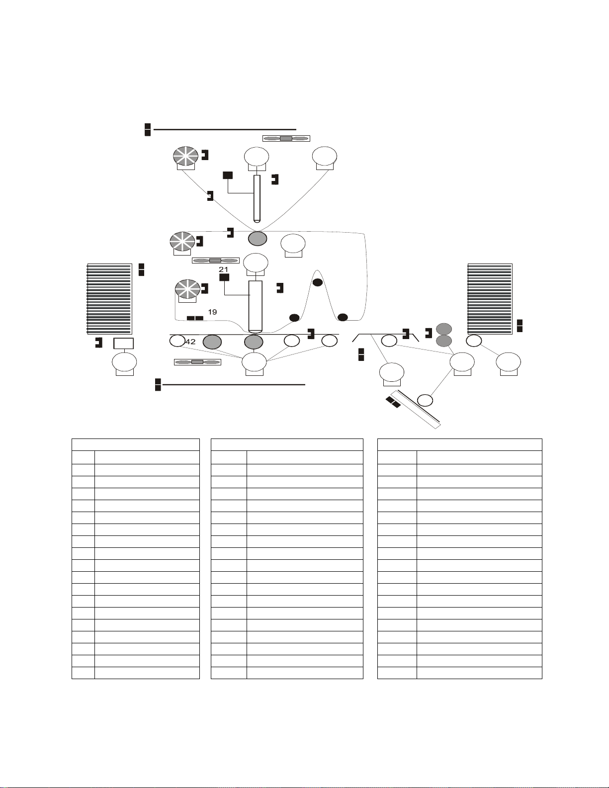
HDP 800 Series Card Printer/Encoders Overview
Reviewing the HDP 800 Series Block Diagram
30
9
25
2
7
24
11
26
10
7
29
5
0
28
12
8
31
43
20
22
39
18
5
14
15
17
16
23
4
8
4
1
6
33
40
4
Motors Sensors Parts
1 Card Input 13 Card Low 32 Card Input Roller
2 Card Feed Stepper 14 Card Detection 33 Cleaning Cartridge
3 Flipper Stepper 15 Flipper Table Card 34 Flipper Table Roller
4 Lamination Stepper 16 Encoding TOF 35 Flipper Table
5 Print Stepper 17 Flipper Home 36 Encoding Module
6 Lamination Headlift 18 Card TOF 37 Encoding Feed Roller
7 Film Supply 19 Lower Film 38 Card Feed Roller
8 Film Take Up 20 Film Take Up Encoder 39 Card Feed Roller
9 Ribbon Supply 21 Thermocouple 40 Platen Roller
10 Ribbon Take Up 22 Film Supply Encoder 41 Flattener Roller
11 Print Headlift 23 Upper Film 42 Card Feed Roller
12 Stacker Lift 24 Ribbon Sensor Array 43 Flattener Cooling Fan
25 Ribbon Encoder 44 Lamination Roller
26 Print Headlift 45 Transfer Platen Roller
27 Thermistor 46 Printhead
28 Stacker Lift 47 Printhead Cooling Fan
29 Stacker Full 48 Film Cooling Fan
30 Cover Interlock 49 Card Input Hopper
31 Release Lever 50 Card Output Stacker
HDP 800 Series Card Printer/Encoders Service Manual (Rev. 5.0)
vi
Page 7
RESTRICTED USE ONLY FARGO Electronic, Inc.
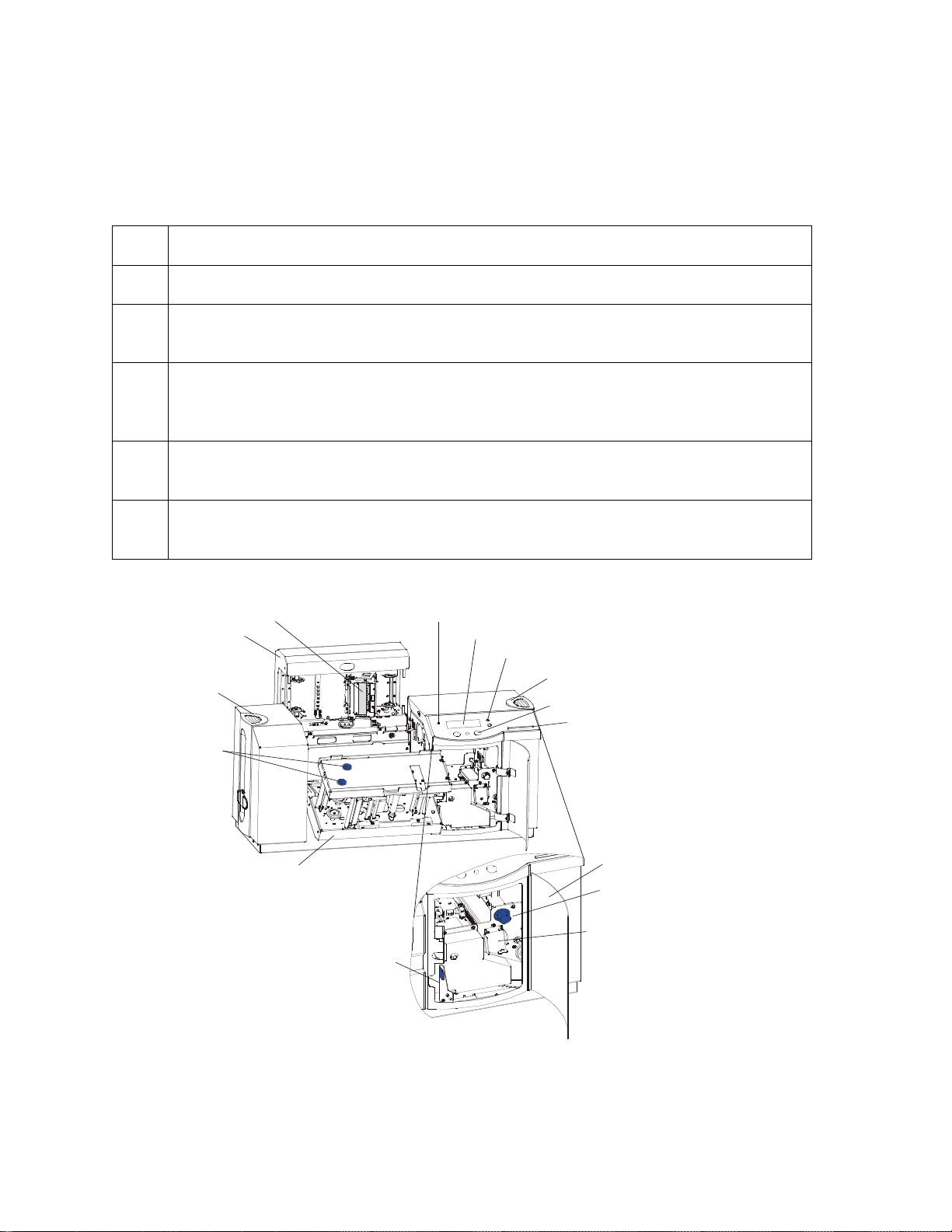
LCD Display
Softkey Buttons
Card Input Hopper
Front Access Door
Reviewing HDP 800 Series Card Printer - Sequence of Operations
The following sequence describes a dual sided full color print job with magnetic encoding. This
Printer also has an optional Card Stacker installed. (Note: The HDP825/825-LC Printers have
two (2) Card Input Hoppers that load 100 cards in each Hopper.)
Step
Process
1 The File information is received from the PC.
2 The Heater warms up and/or maintains the heat on the hot Roller using the
Thermocouple to help maintain the desired temp.
3 The Ribbon Drives turn ON and move until the correct panel is found by the Print
Ribbon Sensor array (5 reflective). All stop. (Note: The Print Ribbon Encoder is
active during this step.)
4 The Film Ribbon Drive turns ON until the Film is positioned with the Film alignment
Sensor. All stop. (Note: The Film Ribbon Encoder is active during this step.)
5 The Headlift Motor engages, moving the Printhead down until Headlift Sensor is
activated. All stop.
Continued on the next page
Print Station
Printhead
Card Output
Hopper
Film Tension
Knobs
LED Light
Scroll Buttons
Access
Card Slot
HDP 800 Series Card Printer/Encoders Service Manual (Rev. 5.0)
Transfer Station
Release Lever
Card Thickness
Adjustment Knob
Card Cleaning
Assembly
vii
Page 8

RESTRICTED USE ONLY FARGO Electronic, Inc.
Reviewing HDP 800 Series Card Printer - Sequence of Operations (cont.)
Step Process
5 The Fan turns ON as required to keep head cool.
6 The Ribbon Drives, Film Ribbon Drive and Stepper turn ON and the Printhead
burns the image data until the image data is depleted. All stop. (Note: The
Ribbon Encoders are active during this step.)
7 The Headlift Motor engages, moving the Printhead up until the Headlift Sensor is
activated. All stop.
8 The Ribbon Drives and Film Ribbon Drive advance until the Print Ribbon Encoder
sees acceleration at release. (Note: The Ribbon Encoders are active during this
step.)
9 The Ribbon Drives move until the Print Ribbon Position Sensor finds the next
panel. All Motors stop. (Note: The Ribbon Encoder is active during this step.)
10 The Film ribbon drive turns ON until the images portion of the Film is positioned
before the Printhead, using the Film Alignment Sensor. All stop. (Note: The
Ribbon Encoder is active during this step.)
11 The Headlift Motor engages, moving printhead down until the Headlift Sensor is
activated. All stop.
12 Ribbon Drive, Film Ribbon Drive and Stepper all turn ON and the Printhead burns
image data until the image data is depleted. All stop. (Note: The Ribbon
Encoders are active during this step.)
13 The Headlift Motor engages, moving the Printhead up until the Headlift Sensor is
activated. All stop.
14 The Ribbon Drive and Film Ribbon Drive engage until print ribbon encoder sees
acceleration at release. (Note: The Ribbon Encoders are active during this step.)
15 Repeat Steps 9 to 14 for the appropriate number of color/heat seal panels.
Continued on the next page
HDP 800 Series Card Printer/Encoders Service Manual (Rev. 5.0)
viii
Page 9

RESTRICTED USE ONLY FARGO Electronic, Inc.
o create a slack region between the Printer and Laminator sections. All stop.
Reviewing HDP 800 Series Card Printer - Sequence of Operations (continued)
Step Process
16 The Ribbon Drives turn ON to advance the printed portion of the Film to a position
near the heated lam Roller using the Lamination Film Alignment Sensor.
The Ribbon Drive stays ON for a certain number of additional clicks after turns
OFF t
(Note: Ribbon encoders and dancer zero position switch are active during this
step.)
17 The Ribbon Drive is used with the Lamination Film Alignment Sensor to locate the
printed Film more precisely under the hot Roller. All stop.
18 This is simultaneous to Steps 1 to 17 and then Steps 19 to 24 will occur.
19 The DC Motor and Stepper Motor turn ON and run until a card is seen by the card
Sensor, which will cause the Card Input Motor to stop.
The Stepper will continue to run a certain number of steps to position the card on
the Flipper Table. All stop. Card Low Sensor will check for cards in Input Hopper.
20 Stepper will turn ON, causing the Flipper to turn to the magnetic angular position.
The Flag Sensor and counted steps are used to determine the angular position.
All stop.
21 Stepper will engage to drive the card past the Mag Card Sensor and the Mag
Head.
22 Stepper engages to drive the card to a centered position on the Flipper Table
using the Mag Card Sensor and a step count. All stop.
23 Stepper will turn ON, causing the Flipper to turn to the default (flat) position. The
Flat Sensor and counted steps are used to determine the angular position. All
stop.
24 Steppers engage to move the card OFF the Flipper and to a position near the hot
Roller, using Card Feed Sensors and a step count. All stop.
25 Stepper engages to move the card to a position directly under the hot Roller. The
Top of Form Sensor determines card edge and number of steps to position card.
All stop.
Continued on the next page
HDP 800 Series Card Printer/Encoders Service Manual (Rev. 5.0)
ix
Page 10

RESTRICTED USE ONLY FARGO Electronic, Inc.
Reviewing HDP 800 Series Card Printer - Sequence of Operations (continued)
Step Process
26 If the heater is not at the required temperature yet, the job will pause.
27 The Headlift Motor turns ON to lower the hot Roller and will stop when the Headlift
Sensor is activated. All off.
28 The Stepper and Ribbon Drive engage to laminate the printed Film onto the card.
They will turn off after a given number of steps based on the position given by the
card Sensor. All stop. (Note: The Ribbon Encoder is active during this step.)
29 The Headlift Motor turns on to raise the hot Roller, stopping when the Headlift
Sensor is activated.
30 The Ribbon Drive and Stepper turn ON for a given number of clicks based on
ribbon encoder, until the ribbon is released.
31 The Stepper turns ON to move the card through the flattening section and into the
output hopper (based on steps from a known position). All stop.
32 The Heater and Thermocouple are maintained at a set temperature at all times
when the Printer is ON. The cooling fan is ON when the Printer is ON.
33 The Stacker Lift Motor engages until the Stacker Lift Sensor is activated.
34 The Stacker Full Sensor checks for presence of cards.
HDP 800 Series Card Printer/Encoders Service Manual (Rev. 5.0)
x
Page 11

RESTRICTED USE ONLY FARGO Electronic, Inc.
Reviewing the HDP 800 Series Card
Printer/Encoders - Boot up Sequence
Step Process
1 The Card feed stepper turns ON (to check for a card on the Flipper table).
2 The Lam Headlift turns until the head up position is returned from the Headlift
Sensor).
3 The Film transfer take-up Motor turns ON to take up any slack in the dancer (and
runs until the Dancer Down Sensor is activated).
4 The Print Headlift turns until head up position is returned from Headlift Sensor.
5 The Print Ribbon moves forward until it finds the yellow panel, pauses, advances
to magenta, then backs up to yellow (the Ribbon Sensor detects marks on the
ribbon).
6 The Transfer Ribbon advances forward two panels from supply (advances until
the Print Film Sensor senses 2 marks on the Film).
7 The Transfer Ribbon advances forward one panel onto take up (advances until
the Transfer Film Sensor senses 1 mark on the Film)
8 The Transfer Ribbon advances forward one panel from supply (advances until
the Print Film Sensor senses 1 mark on the Film).
9 The Transfer Ribbon advances forward one panel onto take up (advances until
the transfer Film Sensor senses 1 mark on the Film).
10 The Transfer Ribbon reverses for one panel from take up (reverses until transfer
the Film Sensor senses 1 mark on the Film).
11 The Transfer Ribbon reverses for one panel onto supply (reverses until the Print
Film Sensor senses 1 mark on the Film).
12 The Transfer Ribbon reverses for one panel from take up (reverses until the
Transfer Film Sensor senses 1 mark up on the Film).
13 The Transfer Ribbon reverses for one panel onto supply (reverses until the Print
Film Sensor senses 1 mark on the Film).
HDP 800 Series Card Printer/Encoders Service Manual (Rev. 5.0)
xi
Page 12
RESTRICTED USE ONLY FARGO Electronic, Inc.
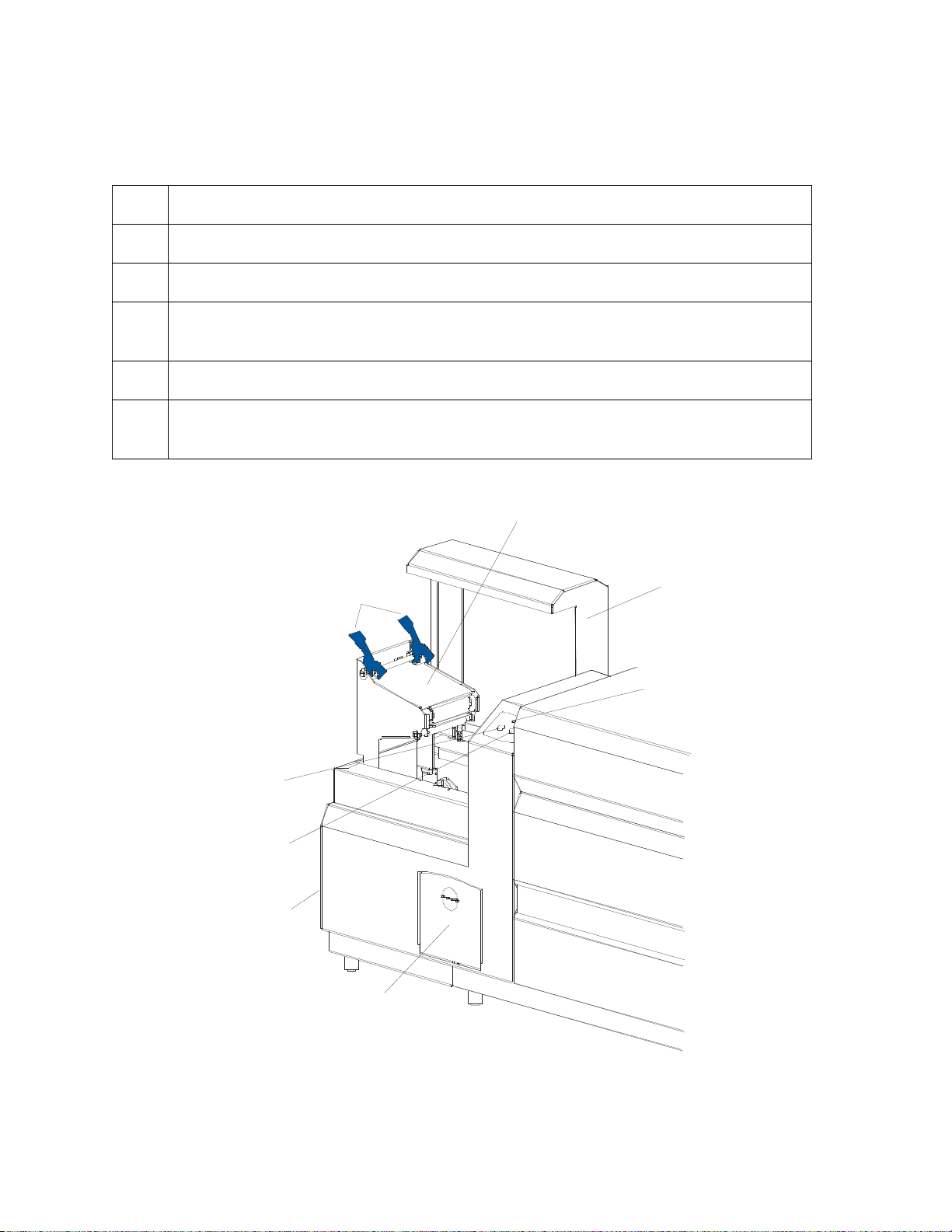
Lamination Station
Reviewing the Lamination Module Sequence of Operations
The LAM sequence of operations begins after printing has occurred with the Card Printer.
Step
Process
1 The card is fed onto the Lamination Module Flipper Table.
2 The card is fed to the Card Position Sensor.
3 The Lamination Ribbon Motor begins cycling until the Upper Lamination Sensor
detects the mark.
4 The Card Feed Motor activates to center the card on the Platen Roller.
5 The Lamination Roller Lift Motor cycles until the Lamination Roller Lift Sensor
detects state change.
Continued on the next page
Securing
Latches
Lamination
Top Cover
Cancel
Button
Resume
(pause) Button
Card Output
Hopper
Lamination
LED Light
Rejection
Card Hopper
HDP 800 Series Card Printer/Encoders Service Manual (Rev. 5.0)
xii
Page 13

RESTRICTED USE ONLY FARGO Electronic, Inc.
Reviewing the Lamination Module Sequence of Operations (continued)
Step Process
6 The Card Feed Motor and the Lamination Ribbon Motor activate for the length of
the card.
7 The Lamination Roller Lift Motor cycles until the Lamination Roller Lift Sensor
detects state change.
8 The card is fed back to the Flipper Table.
9 The Flipper Table Clutch engages.
10 The Flipper Table Motor activates until the Card is inverted based on the Flipper
offset setting.
11 The Flipper Table Clutch disengages.
12 The card is fed off the Flipper Table.
13 The Flipper Table Clutch engages.
14 The Flipper Table Motor activates until the Flipper Table is homed.
15 The Flipper Table Clutch disengages.
16 Repeat Steps 2 through 7.
17 The card is fed out of the Printer.
HDP 800 Series Card Printer/Encoders Service Manual (Rev. 5.0)
xiii
Page 14

RESTRICTED USE ONLY FARGO Electronic, Inc.
Reviewing Lamination Module Boot up Sequence
Step Process
1 The Lamination Headlift turns until the head up position is returned from Headlift
Sensor.
2 The Lamination Ribbon Motor activates to determine the presence of a roll of
lamination.
3 The Lamination Flipper table homes itself.
4 The Card Sensor checks for the presence of a card and ejects it if found.
HDP 800 Series Card Printer/Encoders Service Manual (Rev. 5.0)
xiv
Page 15

RESTRICTED USE ONLY Fargo Electronics, Inc.
Table of Contents
Section 1: Specifications _________________________________________________ 10
Reviewing the HDP800 Series Printers Overview table ________________________ 10
Regulatory Compliances ________________________________________________ 11
Agency Listings _______________________________________________________ 11
Technical Specifications ________________________________________________ 12
Functional Specifications________________________________________________ 16
Printer Components: Access Card Slot to Parallel Interface Port_______________ 17
Printer Components: LCD and Softkey Control Pad ________________________ 25
Printer Components: Centronics-Type Parallel Interface _____________________ 31
Printer Components: Print Ribbons _____________________________________ 32
Printer Components: Blank Cards_______________________________________ 33
Printer Components: Card Input Hopper (HDP820/820-LC) __________________ 34
Printer Components: Card Input Hopper (HDP825/825-LC) __________________ 35
Printer Components: Card Output Hopper ________________________________ 36
Printer Components: Lamination Roller __________________________________ 37
Reviewing the Card Lamination Module____________________________________ 38
Reviewing the Lamination Top Cover and Station __________________________ 39
Reviewing the Securing Latches and Lamination LED Light __________________ 40
Reviewing the Cancel button ___________________________________________ 41
Reviewing the Resume (pause) button____________________________________ 42
Reviewing the Rejection Card Hopper and Card Output Hopper _______________ 43
Reviewing the Module and Printer interaction _____________________________ 44
Reviewing the Module and LCD Display interaction ________________________ 45
Reviewing the Module’s Programmed Default Temperature __________________ 46
Reviewing the Laminator Temperature Adjustment _________________________ 47
Reviewing the Overlaminates ____________________________________________ 48
Reviewing the Thermal Transfer Film and PolyGuard Overlaminates ___________ 48
Reviewing the CR-90 or CR-100 Patch Size _______________________________ 49
Reviewing the Overlaminate Design _____________________________________ 49
Section 2: General Troubleshooting _______________________________________ 50
LCD/SmartGuard Messages______________________________________________ 50
Reviewing LCD Messages_____________________________________________ 50
Reviewing SmartGuard™ Error and Status Messages _______________________ 58
Communications Errors _________________________________________________ 60
Resolving the Communication Errors ____________________________________ 60
Firmware Errors _______________________________________________________ 63
Resolving the Upgrade Failed error ______________________________________ 63
Card Feeding Errors ____________________________________________________ 65
Resolving the Card Feeding problem (HDP820/820-LC) _____________________ 65
Resolving the Card Feeding Errors (HDP825/825-LC)_______________________ 68
Resolving the stalled Cards on or at the Feed Rollers ________________________ 71
Resolving the jammed Cards on the Flipper Table __________________________ 71
Resolving the Flipper Alignment Error Message____________________________ 72
Resolving the Cards being fed improperly off the Flipper Table _______________ 73
HDP 800 Series Card Printer/Encoders Service Manual (Rev. 5.0)
1
Page 16

RESTRICTED USE ONLY Fargo Electronics, Inc.
Resolving the Card Jam Error Message___________________________________ 74
Resolving the Card Jam: Lam Error Message______________________________ 75
Magnetic Encoding Errors _______________________________________________ 76
Resolving the No ENC Response Error Message ___________________________ 76
Resolving the No Magnetic Encoder Error Message_________________________ 76
Resolving the Failed Magnetic Encode Error Message _______________________ 77
Removing the Card jam in the Printer’s Magnetic Encoding Area ______________ 78
Resolving the Printer being unable to read Encoded Magnetic track Data problem _ 79
Resolving the magnetic stripe Data being printed on a Card problem ___________ 80
E-card Encoding Errors _________________________________________________ 81
Resolving the Job Mismatch error _______________________________________ 81
Removing the Card jam in the Printer’s Smart Card Encoding Area ____________ 82
Resolving the No Prox Encoder Error Message ____________________________ 83
Resolving the No Smart Encoder Error Message ___________________________ 83
Resolving the Failed Smart Encode Error Message__________________________ 84
Printing Process Errors__________________________________________________ 85
Resolving the Ribbon Alignment Error Message ___________________________ 85
Resolving the Print Ribbon Jam_________________________________________ 86
Resolving the Print Ribbon Error Message ________________________________ 86
Resolving the Print Ribbon Out Error Message_____________________________ 87
Resolving the Wrong Print Ribbon Error Message __________________________ 87
Resolving the Unknown Ribbon Type Error Message _______________________ 88
Resolving the Headlift Error Message ____________________________________ 88
Resolving the Printer pausing between Panels problem ______________________ 89
Resolving the Printhead Temp Error Message______________________________ 90
Resolving the Printer Open Error Message ________________________________ 90
Transfer Process Errors _________________________________________________ 91
Resolving the Upper and Lower Film errors _______________________________ 91
Resolving the Film Sensor errors________________________________________ 93
Resolving the Transfer Cooling error ____________________________________ 97
Resolving the Card Jam Error Message___________________________________ 98
Resolving the Temperature Timeout Error Message _________________________ 99
Resolving the Transfer Lift Error Message ________________________________ 99
Resolving the Output Stacker errors ____________________________________ 100
Card Lamination Errors ________________________________________________ 101
Resolving the Overlaminate Jam _______________________________________ 101
Resolving the Card Lamination Placement errors __________________________ 103
Resolving the Lam Error/Out Error Message _____________________________ 104
Resolving the Lamination (not adhering to the card surface) problem __________ 106
Diagnosing the Image Problems _________________________________________ 108
Resolving the Pixel failure problems ____________________________________ 108
Resolving the Card surface debris problems ______________________________ 110
Resolving the incorrect Image Darkness problems _________________________ 113
Resolving the Ribbon wrinkle problems _________________________________ 115
Resolving the excessive Resin Printing problems __________________________ 117
Resolving the incomplete Resin Printing problems_________________________ 118
HDP 800 Series Card Printer/Encoders Service Manual (Rev. 5.0)
2
Page 17

RESTRICTED USE ONLY Fargo Electronics, Inc.
Resolving the HDP Film wrinkle problems_______________________________ 119
Resolving the incomplete Transfer problems _____________________________ 121
Resolving an incomplete transfer on the leading edge problem _______________ 122
Resolving an incomplete transfer on the trailing edge problem _______________ 122
Resolving the Image Placement problems ________________________________ 123
Resolving the poor Image Quality problems ______________________________ 127
Resolving the Image washout on Film problems___________________________ 128
Resolving the Registration problems ____________________________________ 129
Resolving the Card Skewed Image problems _____________________________ 131
Printing a Test Image __________________________________________________ 132
Reviewing the Gray/Align YMC/K Self-Test _____________________________ 132
Reviewing the Color/Resin YMCK Self-Test _____________________________ 133
Reviewing the Color Bars YMC Self-Test _______________________________ 133
Reviewing the Card Count Self-Test ____________________________________ 134
Reviewing the Magnetic Test option ____________________________________ 134
Reviewing the Lamination Color/Resin YMCK+L Self-Test _________________ 135
Section 3: Card Lamination Module______________________________________ 136
Safety Messages (review carefully) _______________________________________ 136
Opening the Card Lamination Module __________________________________ 137
Loading the Overlaminate ____________________________________________ 140
Adjusting the Card Lamination Module ___________________________________ 143
Adjusting the Card Flattener __________________________________________ 143
Adjusting the Card Guide Rail_________________________________________ 145
Adjusting the Internal Card Guide ______________________________________ 149
Attaching the Card Lamination Module _________________________________ 152
Section 4: Printer Adjustments __________________________________________ 164
Safety Messages (review carefully) _______________________________________ 164
Adjusting the Card Size ________________________________________________ 165
Adjusting the Card Input Guide ________________________________________ 166
Adjusting the Card Stacker Output Guide ________________________________ 170
Adjusting the Internal Card Guide ______________________________________ 173
Adjusting the Card Thickness Knob ____________________________________ 176
Fine-Tuning the Card Separator Adjustment Assembly (D840995) ______________ 177
Printing on Alternate Card stocks ________________________________________ 178
Selecting the Right Cards and optimize the HDP Print Process _______________ 178
Selecting the Appropriate HDP Printer Driver settings ______________________ 179
Conducting the Tape Adhesion Test ____________________________________ 181
Printer Driver Options _________________________________________________ 184
Installing Printer Driver Updates _______________________________________ 184
Setting Up the Printer Driver ____________________________________________ 186
Setting up Windows 98SE/Windows Millennium __________________________ 186
Setting up Windows NT/Windows 2000/Windows XP______________________ 186
Using the Device Options tab ___________________________________________ 187
Adjusting the Ribbon Type ___________________________________________ 188
Adjusting the Film Type _____________________________________________ 189
Adjusting for the color matching _______________________________________ 190
HDP 800 Series Card Printer/Encoders Service Manual (Rev. 5.0)
3
Page 18

RESTRICTED USE ONLY Fargo Electronics, Inc.
Adjusting for the Resin Dither _________________________________________ 191
Using the Print Both Sides option ______________________________________ 192
Using the Split 1 Set of Ribbon Panels option_____________________________ 193
Using the Print Back Side First option___________________________________ 194
Using the Print on Back Side Only option________________________________ 195
Using the Rotate Front 180 Degrees or Rotate Back 180 Degrees options _______ 196
Using the Print in Single Card Mode option ______________________________ 197
Using the Link Card to Print Job option _________________________________ 198
Using the Disable Printing option ______________________________________ 199
Using the Image color tab ______________________________________________ 200
Using the Image Transfer tab____________________________________________ 204
Adjusting the Image Position controls ___________________________________ 205
Adjusting the Transfer Dwell Time and Temperature _______________________ 207
Adjusting the Flattener Temperature ____________________________________ 208
Using the K Panel Resin tab_____________________________________________ 209
Selecting the Full Card with the K Panel Resin tab_________________________ 210
Selecting the Defined Area(s) with the K Panel Resin tab ___________________ 211
Selecting the Undefined Area(s) with the K Panel Resin tab _________________ 212
Defining the Area to activate the Card Grid ______________________________ 213
Measuring the Total Card area_________________________________________ 214
Measuring the Area to be positioned on the Card __________________________ 215
Selecting the Print YMC under the K and Print K Only options_______________ 216
Using the Magnetic Encoding tab ________________________________________ 218
Using the Encoding Mode option ______________________________________ 219
Encoding the Mode/Coercivity/Magnetic Track Selection ___________________ 221
Reviewing the Magnetic Track Options _________________________________ 222
Reviewing the Enable MLE Support checkbox____________________________ 223
Reviewing the Verification options _____________________________________ 224
Reviewing the Shift Data Left _________________________________________ 225
Reviewing the ISO Track Locations ____________________________________ 226
Sending the Track Information ________________________________________ 227
Reviewing the Sample String__________________________________________ 228
Reviewing the ASCII Code and Character Table __________________________ 229
Using the Card tab ____________________________________________________ 230
Selecting the Card Size from CR-80, CR-90 or CR-100 _____________________ 231
Selecting the Custom Card Size________________________________________ 233
Selecting the Card Type______________________________________________ 234
Reviewing the Orientation ____________________________________________ 236
Specifying the Copies _______________________________________________ 236
Clicking on the About button__________________________________________ 237
Using the Lamination tab (only with Card Lamination Module) ________________ 238
Selecting the Lamination Position ______________________________________ 239
Selecting the Lamination Side _________________________________________ 240
Selecting the Lamination Type ________________________________________ 241
Adjusting the Transfer Dwell Time and Transfer Temperature________________ 242
Selecting the Sensors button and Defaults button __________________________ 242
HDP 800 Series Card Printer/Encoders Service Manual (Rev. 5.0)
4
Page 19

RESTRICTED USE ONLY Fargo Electronics, Inc.
Selecting the Sensors button and Defaults button __________________________ 243
Section 5: Cleaning ____________________________________________________ 244
Using the Required Supplies __________________________________________ 244
Safety Messages (review carefully) _______________________________________ 245
Cleaning inside the Printer____________________________________________ 246
Cleaning outside the Printer___________________________________________ 246
Cleaning the Printhead _______________________________________________ 247
Cleaning the Cleaning Rollers _________________________________________ 248
Cleaning the Card Feed Rollers ________________________________________ 252
Cleaning the Platen Rollers ___________________________________________ 256
Section 6: Parts Replacement____________________________________________ 258
Safety Messages (review carefully) _______________________________________ 259
Reviewing the Printer Components _______________________________________ 260
Reviewing the Input Hopper Components________________________________ 260
Reviewing the Print Module Components ________________________________ 263
Reviewing the Transfer Station Components _____________________________ 265
Reviewing the Base Module Components ________________________________ 266
Reviewing the Base Module Components ________________________________ 267
HDP Main Board Cable Connections Reference___________________________ 269
HDP Lamination Board Cable Connections Reference______________________ 270
HDP Lamination Module Board Cable Connections Reference _______________ 272
Cover Removal Procedures _____________________________________________ 273
Removing the Print Station cover (840361) ______________________________ 273
Removing the Front Transfer Cover (840362)_____________________________ 274
Removing the Mid Pulley Cover (D840166)______________________________ 275
Removing the Base Module cover (840363) ______________________________ 276
Removing the Card Input Hopper cover (840167) _________________________ 277
Removing the Card Output Hopper cover (840167) ________________________ 277
Removing the Back cover ____________________________________________ 278
Control Panel Assembly Components _____________________________________ 279
Replacing the Control Panel Assembly Components _______________________ 279
Printhead Assembly Components ________________________________________ 281
Replacing the Printhead (D840854)_____________________________________ 281
Replacing the Fan Assembly (D840986) _________________________________ 282
Replacing the Head Force Spring - 2 (840272) ____________________________ 283
Replacing the Ribbon Deflector (D840638) ______________________________ 284
Print Station Components replacement ____________________________________ 285
Replacing the Headlift Drive O-Rings (140212) ___________________________ 285
Replacing the Ribbon Drive O-Ring behind the Encoder Wheel (810492) ______ 286
Replacing the Ribbon Sensor Board Assembly (140407) ____________________ 287
Replacing the Encoder Wheel (810492) _________________________________ 288
Replacing the Ribbon Sensor Array Assembly (840108) ____________________ 289
Replacing the Ribbon Supply Motor Assembly (D840980) __________________ 290
Replacing the Ribbon Take-Up Motor Assembly (D840980) _________________ 291
Replacing the Headlift Motor Assembly (D840980)________________________ 292
Replacing the Ribbon Supply Encoder Sensor Assembly (D840982)___________ 293
HDP 800 Series Card Printer/Encoders Service Manual (Rev. 5.0)
5
Page 20

RESTRICTED USE ONLY Fargo Electronics, Inc.
Replacing the HDP 800 Series Ribbon Hub ______________________________ 294
Replacing the HDP 800 Series Ribbon Take up Roller Hubs _________________ 313
Replacing the HDP 800 Series Film Supply Hub __________________________ 315
Replacing the Headlift Sensor Assembly (D840983) _______________________ 322
Transfer Station Components Replacements ________________________________ 323
Replacing the Film Drive O-Rings (140212)______________________________ 323
Replacing the Film Drive Encoder Wheel - 2 (810492) _____________________ 324
Replacing the Stepper Motor Assembly (840123)__________________________ 325
Replacing the Supply Encoder Sensor Assembly (840135) __________________ 326
Replacing the Lamination Take-Up Encoder Sensor Assembly (840136) _______ 327
Replacing the Lower Film Sensor Assembly (840199) ______________________ 328
Replacing the Upper Film Sensor Assembly (D841023)_____________________ 329
Replacing the Print Platen Roller (D840811) _____________________________ 330
Replacing the Transfer Peel Off Bar Assembly (D840698) __________________ 331
Replacing the Transfer Station Assembly (D841083) _______________________ 332
Replacing the Lamination Assembly (D841085)___________________________ 334
Replacing the Transfer Lift Sensor (A000126) ____________________________ 336
Replacing the Transfer Lift Motor (D840173)_____________________________ 337
Base Module Components Replacements __________________________________ 338
Replacing the Drive Belt – Platen Roller to Card Feed Roller (220071)_________ 338
Replacing the Drive Belt – Card Feed Roller to Card Feed Roller (220082) _____ 339
Replacing the Stepper Motor Assembly (D841045) ________________________ 340
Replacing the Pinch Roller Spring Plate-Front Input Side (D840865) __________ 341
Replacing the Pinch Roller Spring Plate-Front Output Side (D840865) _________ 342
Replacing the Pinch Roller Spring Plate-Back Input Side (D840865) __________ 343
Replacing the Pinch Roller Spring Plate-Back Output Side (D840865) _________ 344
Replacing the Drive Pulley - Back - 2 (D850190)__________________________ 345
Replacing the Gear - Card Transport - 2 (760330) _________________________ 346
Replacing the Compound Gear (D841032) _______________________________ 347
Replacing the Base Module (D841082)__________________________________ 348
Card Input Hopper Components Replacements______________________________ 350
Replacing the Input Hopper (D841087)__________________________________ 350
Replacing the Separator Adjustment Assembly (D840995) __________________ 351
Replacing the Flipper Table Sensor Board Assembly (140407) _______________ 352
Replacing the Card Low Sensor Board Assembly (140407) __________________ 353
Replacing the Cleaning Roller Drive Idler Gear - 2 (760401)_________________ 354
Replacing the Card Feed Gear - 3 (810271) on the Flipper Table Encoder Feed Motor
(E000062)_________________________________________________________ 355
Replacing the Card Feed Shaft Gear on the Cleaning Roller Assembly (810271) _ 356
Replacing the Feed/Encoding Motor Assembly (E000062) __________________ 357
Replacing the Cleaning Roller Assembly (840102)_________________________ 358
Replacing the Flipper Table Position Motor (840124) ______________________ 359
Replacing the Card Feed Motor Assembly (D841105) ______________________ 360
Replacing the Flipper Table Card Sensor Assembly (D840625)_______________ 361
Replacing the Card Feed Sensor (D840624) ______________________________ 362
Replacing the Magnetic Encoder Head (840104) __________________________ 363
HDP 800 Series Card Printer/Encoders Service Manual (Rev. 5.0)
6
Page 21

RESTRICTED USE ONLY Fargo Electronics, Inc.
Replacing the Encoder Card Sensor (140407)_____________________________ 364
Power Assembly Components Replacements _______________________________ 365
Replacing the Power Switch (120011)___________________________________ 365
Replacing the Power Cord Receptacle (130067) ___________________________ 366
Replacing the Main Print Board (A000271) ______________________________ 367
Replacing the Lamination Board (140402) _______________________________ 368
Replacing the Power Supply (150240) __________________________________ 369
Output Stacker Components Replacements_________________________________ 370
Replacing the Output Stacker (D841079) ________________________________ 370
Replacing the Stacker Full Sensor (140407) ______________________________ 371
Replacing the Stacker Lift Motor (840130)_______________________________ 372
Card Lamination Module Component Replacements _________________________ 373
Replacing the Lamination Module Board Cover (D870151)__________________ 373
Replacing the Lamination Module Main Cover (D870159) __________________ 374
Replacing the Lamination Module Main Board (A000250) __________________ 375
Replacing the Lamination Module Arm Assembly (D870153)________________ 376
Replacing the Lamination Module Card Flipper Table Assembly (D870091) ____ 377
Replacing the Card Position Sensor Assembly (D870186) ___________________ 379
Replacing the Lamination Module Flipper Position Sensor (D870188) _________ 380
Replacing the Lamination Module Overlaminate Encoder Sensor (D870189) ____ 381
Replacing the Lamination Module Ribbon ID Sensor (820593) _______________ 382
Replacing the Lamination Module Overlaminate Sensor (D870241) ___________ 383
Replacing the Lamination Module Hopper Sensor Assembly (D870228) _______ 384
Replacing the Lamination Module Platen Motor (D870218) _________________ 386
Replacing the Lamination Module Flipper Table Motor (D870217) ___________ 388
Replacing the HDP820-LC/HDP825-LC Lamination Lid Hinge Bracket _______ 390
Adjusting the HDP820-LC/HDP825-LC Lamination Heat Shield Adjustment ___ 408
HDP820/HDP820-LC Magnetic and Smart Card Module Replacement___________ 414
Replacing the Magnetic/Smart Card Module______________________________ 418
Section 7: Packing the HDP800 Series Card Printer_________________________ 437
Section 8: Board Level Diagnostics _______________________________________ 438
Board Errors_________________________________________________________ 438
Resolving the EE Memory Error _______________________________________ 438
Resolving the EE Checksum Error _____________________________________ 438
Resolving the DRAM Memory Error ___________________________________ 439
Resolving the RAM Memory Error _____________________________________ 439
Resolving the FPGA Error____________________________________________ 439
Sensor Testing _______________________________________________________ 440
Reviewing the Sensor Location and Voltages _____________________________ 441
Reviewing the Sensor Layout on Ribbon Sensor array ______________________ 442
Reviewing the Sensor Location and Voltages for the Lamination Module_______ 443
Section 9: LCD On-Line Menu Navigation ________________________________ 444
Entering the LCD Menu and selecting an Option ____________________________ 444
Selecting from the HDP800 Series Menu Option Structure Tree ______________ 446
Reviewing the Printer Setup ____________________________________________ 447
HDP 800 Series Card Printer/Encoders Service Manual (Rev. 5.0)
7
Page 22

RESTRICTED USE ONLY Fargo Electronics, Inc.
Preparing to Adjust the Print Offset, Transfer TOF and Transfer EOF__________ 449
Aligning the Print Offset _____________________________________________ 450
Setting the Transfer TOF _____________________________________________ 452
Setting the Transfer EOF _____________________________________________ 454
Setting the Transfer EOF _____________________________________________ 455
Adjusting the Transfer Tension ________________________________________ 456
Adjusting the Film Drive _____________________________________________ 457
Adjusting the Ribbon Tension _________________________________________ 457
Adjusting the Ribbon Drive ___________________________________________ 458
Adjusting the Transfer Temperature ____________________________________ 458
Setting the Flattener Temperature ______________________________________ 459
Setting the Printhead Resistance _______________________________________ 459
Adjusting the Image Darkness _________________________________________ 460
Changing the Encoder Settings ________________________________________ 461
Setting the Magnetic TOF ____________________________________________ 462
Setting the Magnetic TOF ____________________________________________ 463
Adjusting the Flipper Offset___________________________________________ 464
Adjusting the Lamination Flipper Offset _________________________________ 464
Adjusting the LAM TOF and EOF _____________________________________ 465
Adjusting the Lamination Sensor Calibration _____________________________ 466
Adjusting the Lamination Temperature Setting____________________________ 466
Show the Error Count _______________________________________________ 466
Using the Show Card Count option _____________________________________ 467
System Upgrade (Firmware Upgrade) ___________________________________ 467
Section 10: Firmware Updates___________________________________________ 468
Firmware Updater Application Program ___________________________________ 468
Downloading Firmware Updates _________________________________________ 470
Updating the Printer's Firmware _________________________________________ 471
Updating the Main Firmware__________________________________________ 471
Updating the LCD Firmware __________________________________________ 474
Firmware Upgrades (as of 10/07/03) ______________________________________ 476
Section 11: Fargo Technical Support _____________________________________ 478
Contacting Fargo Technical Support ______________________________________ 478
Reading the Serial Numbers on a Fargo printer______________________________ 479
Finding out when a Fargo Card Printer was manufactured ___________________ 479
Reviewing Example No. 1: Serial Number 80453289 ______________________ 479
Reviewing Example No. 2: Serial Number A1280224______________________ 479
Section 12: Reviewing Spare Parts Lists___________________________________ 480
Reviewing Spare Parts List for HDP 800 Series Card Printer_________________ 480
Reviewing Spare Parts List for Card Lamination Module____________________ 494
Glossary of Terms _____________________________________________________ 502
Index ________________________________________________________________ 522
Appendix A: Engineering Drawings ______________________________________ 535
HDP 800 Series Card Printer/Encoders Service Manual (Rev. 5.0)
8
Page 23

RESTRICTED USE ONLY Fargo Electronics, Inc.
Appendix B: Technical Updates _________________________________________ 535
Appendix C: Miscellaneous _____________________________________________ 535
HDP 800 Series Card Printer/Encoders Service Manual (Rev. 5.0)
9
Page 24

RESTRICTED USE ONLY Fargo Electronics, Inc.
Section 1: Specifications
The purpose of this section is to provide the User with specific information on the Regulatory
Compliances, Agency Listings, Technical Specifications and Functional Specifications for the
HDP 800 Series Card Printer/Encoders.
Reviewing the HDP800 Series Printers Overview
table
HDP800 Series Input
Hoppers
HDP820 (Dual-Sided
Card Printer/Encoders)
HDP820-LC (DualSided Card
Printer/Encoders)
HDP825 (Dual-Sided
Card Printer/Encoders)
HDP825-LC (DualSided Card
Printer/Encoders)
1 250 CR-80,
1 250 CR-80,
2 200 CR-80 Optional Optional
2 200 CR-80 Optional Included
Card
Capacity
Accepted
Card Size
CR-90 &
CR-100
CR-90 &
CR-100
Encoding
Modules
Optional Optional
Optional Included
Lamination
Module
HDP 800 Series Card Printer/Encoders Service Manual (Rev. 5.0)
10
Page 25

RESTRICTED USE ONLY Fargo Electronics, Inc.
Regulatory Compliances
Term Description
CSA The Printer manufacturer has been authorized by UL to represent
the Card Printer as CSA Certified under CSA Standard 22.2.
File Number: E145118
FCC The Card Printer complies with the requirements in Part 15 of the
FCC rules for a Class B digital device. (Note: These requirements
are designed to provide reasonable protection against harmful
interference in a residential installation.)
If equipment operation in a residential area causes unacceptable
interference to radio and TV reception, the operator is required to
take whatever steps are necessary to correct the interference.
ITS-EMC The Card Printer has been tested and complies with EN55022
Class B: 1995 and EN82082-1: 1997 standards for EMI emissions.
(Note: Based on the above testing, the Printer manufacturer
certifies that the Card Printer complies with all current EMC
directives of the European Community and has placed the CE mark
on the Card Printer.)
License Number: J99032510
TÜV-GS The Card Printer has been tested and complies with IEC950 and
bears the TÜV-GS mark.
License Number: S9971826
UL The Card Printer is listed under UL 1950 INFORMATION
TECHNOLOGY EQUIPMENT.
File Number: E145118, Volume 1, Section 15
Agency Listings
Term Description
Emissions
Standards
CE, FCC, CRC c1374, BSMI, ITS (EN 55022 Class B:1995, FCC Class
B, EN 82082-1:1997).
Safety
Standards
HDP 800 Series Card Printer/Encoders Service Manual (Rev. 5.0)
UL 1950, CSA C2.2 No.950-95 and TüV-GS (EN 60950 A1-A4, A11).
11
Page 26

RESTRICTED USE ONLY Fargo Electronics, Inc.
Technical Specifications
Term Description
Accepted
Standard Card
Sizes
Accepted Card
Thickness
Accepted
Electronic Card
types
HDP820/820-LC:
• CR-80: 3.375 in. x 2.125 in. (85.6mm x 54mm) (corresponds to
ID1)
• CR-90: 3.63 in. x 2.37 in. (92mm x 60mm)
• CR-100: 3.88 in. x 2.63 in. (98.5mm x 67mm); laminate with CR-
90 or CR-100 size PolyGuard only if laminating with HDP800
Series-LC
HDP825/825-LC:
• CR-80: 3.375” L x 2.125” W/85.6mm L x 54mm W
.030 in. (30 mil) to .070 in. (70 mil) (.762mm to 1.778mm). (30 mil
maximum for CR-100 size cards)
(.030" to .040"/.762mm to 1.02mm if laminating with HDP800 SeriesLC; thicker cards are allowed to pass through the Lamination Module if
you choose to print-only)
HID Proximity Cards, MIFARE Contactless Smart Cards and Contact
Smart Cards
Accepted Card
Compositions
Colors Up to 16.7 million colors and 256 shades per Pixel.
Card Capacity
Dimensions
ABS, PVC, PET and PETG
HDP820/HDP820-LC: 250 cards (.030"/.762mm); auto or manual
feed
HDP825/HDP825-LC: 200 cards (.030"/.762mm) auto or manual feed
• HDP820/825: 15” H x 26.1” W x 14"D/381mm H x 663mm W x
356mmD
• HDP820-LC/825-LC: 15” H x 34.75” W x 14"D/381mm H x
883mm W x 356mmD
• LC Module: 14.2” H x 13” W x 10”D/362mm H x 330mm W x
254mmD
HDP 800 Series Card Printer/Encoders Service Manual (Rev. 5.0)
12
Page 27

RESTRICTED USE ONLY Fargo Electronics, Inc.
Technical Specifications (continued)
Term Description
Display User-friendly, SmartScreen LCD Control Panel; LED display on
Card Lamination Module.
Encoding Options
Fargo Certified
Supplies
HDP Film Options
• ISO Magnetic Stripe Encoding Module, dual high- and low-
coercivity, Tracks 1, 2 and 3
• JIS II Magnetic Stripe Encoding Module
• E-card Docking Station (required for all e-card options or 3rd
party smart card encoding)
• Contact Smart Card Encoder (ISO 7816), Parts 1-4; T=0 & T=1
• Contactless Smart Card Encoder (MIFARE
®
)
• Prox Card Encoder (HID read-only) (Note: Corporate Express
1000 Cards can be used with special order Weigand/ASCII
Converter)
Fargo Card Printer/Encoders require highly specialized media to
function properly. To maximize printed card quality and durability,
printhead life and printer/encoder reliability, use only Fargo Certified
Supplies, Fargo warranties are void, where not prohibited by law,
when non-Fargo Certified Supplies are used.
• Clear, 1,250 prints
• Standard Holographic
• Custom Holographic, special order
HDP Film Storage
77ºF (25ºC) or lower for no longer than 1.5 years.
Temperature
Humidity 20% to 80% Non-Condensing.
Input Hopper Card
Capacity
Interface
HDP820/HDP820-LC: 250 cards (.030"/.762mm)
HDP825/HDP825-LC: 200 cards (.030"/.762mm)
• Centronics parallel, IEEE-1284 Compliant
• Optional USB to Parallel Adaptor
• Interfacing information for E-card Options
HDP 800 Series Card Printer/Encoders Service Manual (Rev. 5.0)
Continued on the next page
13
Page 28

RESTRICTED USE ONLY Fargo Electronics, Inc.
Technical Specifications (continued)
Term Description
Maximum Accepted
(HDP825/825-LC only) 2.125 in. to 2.63 in. (54mm to 67mm).
Card Width Range
Maximum Accepted
3.375 in. to 3.88 in. (85.6mm to 98.5mm).
Card Length Range
Memory 8 MB RAM; expandable to 32 MB RAM.
Operating
65ºF to 80ºF (18ºC to 27ºC).
Temperature
Options The options are the 32MB RAM Upgrade Kit, Printer Cleaning Kit,
External Print Server (Windows only; required for stand-alone
networking of printer/encoders), Card Lamination Module and USBto-Parallel Interface Cable (Windows 98/Me/2000/XP only).
Output Hopper
Card Capacity
Overlaminate
Options (HDP800
Series-LC only)
100 cards (.030"/.762mm); 250 cards with optional Card Output
Stacker
All overlaminates are available in either clear, holographic globe
design or custom holographic design. They can also be optimized
for use with smart cards and Magnetic Stripes. PolyGuard available
in CR-80, CR-90 and CR-100 patch sizes. Here are the options:
• Thermal Transfer Overlaminate, .25 mil thick, 500 prints
• PolyGuard Overlaminate, .6 mil thick, 250 prints
• PolyGuard Overlaminate, 1.0 mil thick, 125 prints
Print Area Over-the-edge on all accepted standard card sizes (YMCKH ribbon
required for over-the-edge printing on CR-100 cards).
Print Method HDP Dye-Sublimation/Resin Thermal Transfer
Printing Method HDP™ Dye-Sublimation/Resin Thermal Transfer.
Printing Resolution Up to 16.7 million colors and 256 shades per Pixel.
Continued on the next page
HDP 800 Series Card Printer/Encoders Service Manual (Rev. 5.0)
14
Page 29

RESTRICTED USE ONLY Fargo Electronics, Inc.
Technical Specifications (continued)
Term Description
Print Ribbon
Options
• Full color, YMC, 700 prints
• Full color with resin black, YMCK, 250 or 500 prints
• Full color with two resin black Panels, YMCKK, 400 prints
• Full color with resin black and heat seal Panel for difficult to print
surfaces, YMCKH, 400 prints; extra wide for over-the-edge
printing on CR-100 cards
All HDP ribbons utilize Fargo's exclusive RibbonTraq™ system for
maximum print quality, performance, reliability and ease of use.
Print Speed-Batch
Mode
• 35 seconds per card/112 cards per hour (YMC with transfer)
• 38 seconds per card/94 cards per hour (YMCK with transfer)
• 66 seconds per card/54 cards per hour (YMCKK with transfer)
• 40 seconds per card/90 cards per hour (YMCK/Lamination)*
• 72 seconds per card/50 cards per hour (YMCKK/Lamination)*
Resolution 300 dpi (11.8 dots/mm)
Software Drivers Windows 95/ 98/ ME/ NT/ 2000/XP.
Supply Voltage 100 to 240 VAC, 3.75A.
Supply Frequency 50 Hz/60 Hz.
System
Requirements
IBM-PC or compatible. Windows 95/ 98/ ME/ NT/ 2000/XP.
Pentium
™
class 133 MHz computer with 32 MB of RAM or higher,
200 MB free hard disk space or higher and ECP parallel port with
DMA access.
Warranty
Printer: One year; optional Extended Warranty Program (U.S.
only)
Printhead: Lifetime; unlimited pass
Weight
HDP820/825: 70 lbs. (31.8kg).
HDP820-LC/825-LC: 87 lbs./39.5kg
LC Module: 21 lbs./9.5 kg
HDP 800 Series Card Printer/Encoders Service Manual (Rev. 5.0)
15
Page 30

RESTRICTED USE ONLY Fargo Electronics, Inc.
Functional Specifications
The Card Printer utilizes two different, yet closely related printing technologies to achieve its
remarkable direct-to-card print quality for dye-sublimation and resin thermal transfer. The
Card Printer will print from any IBM-PC® or compatible running Windows® 98Se/Me,
Windows NT 4.0, Windows 2000 or Windows XP Pro.
The following describes how each of these technologies works:
Function Description
DyeSublimation
Dye-Sublimation is the print method the Card Printer uses to produce
smooth, continuous-tone images that look photographic. (Note: This
process uses a dye-based ribbon roll that is partitioned by a number of
consecutive color Panels.)
• Process colors: The Panels are grouped in a repeating Series of
three process colors - yellow, magenta and cyan (YMC), along the
entire length of the Print Ribbon.
• Panels: The Printer always prints the yellow Panel first, followed by
the magenta Panel and the cyan Panel.
• Printhead: As the Print Ribbon passes beneath the Printhead,
hundreds of thermal elements within the Printhead heat the dyes on the
ribbon. (Note: When these dyes are heated, they vaporize and diffuse
into the surface of the card. A separate pass is made for each of the
three color Panels on the ribbon.)
• color Shades: By combining the colors of each Panel and by varying
the heat used to transfer these colors, it is possible to print up to 16.7
million different shades of color. (Note: This blends one color smoothly
into the next, producing photo-quality images with absolutely no dot
pattern.)
• Dye-Diffusion Thermal Transfer: It is the process of heating a dye
suspended in a cellulous substrate until the dye can flow, diffusing into
the dye receptive surface of the card or InTM. This produces the image
in the surface of the card.
HDP 800 Series Card Printer/Encoders Service Manual (Rev. 5.0)
Continued on the next page
16
Page 31

RESTRICTED USE ONLY Fargo Electronics, Inc.
Printer Components: Access Card Slot to Parallel Interface Port
Component Description
Resin Thermal
Transfer
Access Card
Slot
Card Input
Hopper
Card Output
Hopper
Card
Lamination
Module
Resin Thermal Transfer is the print method the Printer uses to print
sharp black text and crisp bar codes that can be read by both infrared
and visible-light bar code scanners.
Like dye-sublimation, this process uses the same thermal Printhead to
transfer color to a card from a resin-only Print Ribbon or the resin black
(K) Panel of a full color Print Ribbon.
The difference, however, is that solid dots of resin-based ink are
transferred and fused to the surface of the card. (Note: This produces
very durable, saturated printing.)
If using the Printer's optional SmartGuard Security Feature, this is the
slot in which a SmartGuard Access Card is inserted.
Load blank cards into this hopper.
Stores printed cards.
Works in conjunction with the Printer to apply a variety of different
overlaminates to printed cards, providing increased card durability and
security. The Module has its own LED indicator light and control
buttons; so it can be operated separately from the Printer. (Note:
When printing a batch of cards, the Printer can be encoding and
printing one card while the Lamination Module laminates another card.)
See Section 3: Card Lamination Module
on page 136.
HDP 800 Series Card Printer/Encoders Service Manual (Rev. 5.0)
Continued on the next page
17
Page 32

RESTRICTED USE ONLY Fargo Electronics, Inc.
Printer Components: Access Card Slot to Parallel Interface Port (continued)
Component Description
Card Output
Guide
If the Printer is equipped with an optional Card Output Stacker, adjust
the stacker's Card Output Guide to the proper card size prior to printing,
as shown below. (Note: This will ensure consistent card ejecting and
stacking.)
HDP 800 Series Card Printer/Encoders Service Manual (Rev. 5.0)
18
Page 33

RESTRICTED USE ONLY Fargo Electronics, Inc.
Printer Components: Access Card Slot to Parallel Interface Port (continued)
Component Description
Film Tension
Knobs
Allows you to manually tighten the HDP film after loading or whenever
the Transfer Station is opened, as shown below.
Continued on the next page
HDP 800 Series Card Printer/Encoders Service Manual (Rev. 5.0)
19
Page 34

RESTRICTED USE ONLY Fargo Electronics, Inc.
Softkey Buttons
Printer Components: Access Card Slot to Parallel Interface Port (continued)
Component Description
Front Access
Door
LCD Display Displays the current status of the Printer.
LED Light Indicates the Printer ON, OFF, pause and error conditions.
Print Station Prints images onto the HDP film.
Printhead The component of the Print Station that actually does the printing. This
Softkey Buttons Current function is displayed above the button and will change
Opens to allow access to the inside of the Printer.
component is fragile and must not be bumped or touched with anything
other than a cleaning pen.
depending upon the Printer's mode of operation.
Continued on the next page
Scroll Buttons
HDP 800 Series Card Printer/Encoders Service Manual (Rev. 5.0)
20
Page 35

RESTRICTED USE ONLY Fargo Electronics, Inc.
Unlock Release Lever
Transfer Stations
Print Station
Printer Components: Access Card Slot to Parallel Interface Port (continued
Component Description
Scroll Buttons Used to scroll through menus and sub-menus and to adjust certain
menu options.
Transfer Station Transfers printed images and the HDP film to blank cards.
Transfer Station
HDP 800 Series Card Printer/Encoders Service Manual (Rev. 5.0)
to open Print and
21
Page 36

RESTRICTED USE ONLY Fargo Electronics, Inc.
Printer Components: Access Card Slot to Parallel Interface Port (continued)
Component Description
Card Thickness
Adjusts the Printer to feed varying card thicknesses.
Adjustment
Knob
Card Cleaning
Assembly
Automatically cleans cards for higher print quality. (Note: Clean this
assembly after every 250 cards or as needed.)
Power Switch Turns the Printer power ON and OFF.
Power Port Connect to the included power cord.
Parallel
Connect to a Windows PC with a parallel cable. See below.
Interface Port
HDP 800 Series Card Printer/Encoders Service Manual (Rev. 5.0)
22
Page 37

RESTRICTED USE ONLY Fargo Electronics, Inc.
Printer Components: Access Card Slot to Parallel Interface Port (continued)
Component Description
Release Lever Locks and unlocks the Print and Transfer Stations so they can be
opened and closed. (Note: This lever must be in its locked position in
order for the Printer to begin printing.)
HDP 800 Series Card Printer/Encoders Service Manual (Rev. 5.0)
23
Page 38

RESTRICTED USE ONLY Fargo Electronics, Inc.
LCD Display
Softkey Buttons
Card Input Hopper
Front Access Door
Printer Components: Access Card Slot to Parallel Interface Port (continued)
Refer to the previous table.
Print Station
Card Output
Hopper
Film Tension
Knobs
Transfer Station
Printhead
Release Lever
LED Light
Scroll Buttons
Access
Card Slot
Card Thickness
Adjustment Knob
Card Cleaning
Assembly
HDP 800 Series Card Printer/Encoders Service Manual (Rev. 5.0)
24
Page 39

RESTRICTED USE ONLY Fargo Electronics, Inc.
Printer Components: LCD and Softkey Control Pad
The Printer provides a four line, eighty (80) character LCD Displays that can communicate
helpful information about the Printer's operation.
• The top three lines of the LCD Display will always be used to communicate print status,
error messages and menu options.
• The bottom line of the LCD Display will always be used to communicate the current
function of the Printer's softkey buttons.
This section describes how the LCD Display and Softkey Control Pad work together.
Component Description
Softkey
Buttons
The Printer has three softkey buttons that appear below the LCD
Display. Their current function is indicated by the words appearing above
them. This function will change according to the Printer's current mode of
operation.
• Press the corresponding softkey button under the choice you want to
select. If no word appears above a particular button, this indicates it
has no function in that particular mode of operation. The Printer also
has another type of button on its control pad called scroll buttons.
These buttons are located just to the right of the LCD Display.
• Use these buttons to scroll through help text, to navigate through the
Printer's menus and to adjust certain Printer settings.
LCD Display The Printer's LCD Display will change according to the Printer's current
mode of operation.
System Check
Screens
When the Printer is first powered ON, the Printer's system check screens
will briefly appear to display and test the amount of installed Printer
memory, align the Print Ribbon and HDP film and lastly to display the
READY screen and current Firmware version.
Continued on the next page
HDP 800 Series Card Printer/Encoders Service Manual (Rev. 5.0)
25
Page 40

RESTRICTED USE ONLY Fargo Electronics, Inc.
Printer Components: LCD and Softkey Control Pad (continued)
Component Description
Ready/Printer
Open Screens
Once the Printer has finished its system check and with the Print and
Transfer Stations closed, the Printer will display READY to indicate that
the Printer is ready for operation. (Note: The Printer will stay in this
mode until it receives a print job or it is turned OFF.)
• If the Release Lever is unlocked, the Release Lever Unlocked screen
will appear to remind you this item is open.
• If the Print and Transfer Stations are opened, the Printer Open
screen will appear. Press either the Forward or Back buttons to
move the Printer's card path rollers in the indicated direction. Use the
scroll buttons to select between moving the Print-Side Card Rollers or
the Input-Side Card Rollers. This is helpful when cleaning the Printer
or if clearing jammed media. In any of these screens, the Printer will
always display the Menu option above the center softkey button.
Press this button to access the Printer's menu options. (Note: The
Menu option is available only in the Ready/Printer Open screens.)
• If the Printer is equipped with the Card Lamination Module and the
Lamination Station is opened, no LCD message will appear. Instead,
the Lamination Module's LED will flash. (Note: To move the
Lamination Module's rollers, push the Module's Cancel or Resume
buttons.)
• If both the Print Station and Lamination Station are open, the LCD's
FORWARD and BACK softkey buttons will move ALL rollers. In any
of these screens, the Printer will always display the MENU option
above the center softkey button. Press this button to access the
Printer's menu options. (Note: The MENU option is available only in
the READY/PRINTER OPEN screens.)
HDP 800 Series Card Printer/Encoders Service Manual (Rev. 5.0)
Continued on the next page
26
Page 41

RESTRICTED USE ONLY Fargo Electronics, Inc.
Printer Components: LCD and Softkey Control Pad (continued)
Component Description
Print Status
Screen
During operation, the LCD will indicate the current Print Status by
showing you the area of the Printer that is active. It does this by
displaying the following icons on the second line:
• FDR Indicates the Feeder Station is feeding a blank card into the
Printer.
• ENC Indicates the Encode Station is encoding a card (appears only if
you are using a Printer with an optional built-in Encoding Module).
• PRT Indicates the Print Station is printing onto the HDP film.
• TFR Indicates the Transfer Station is transferring an image to a blank
card.
• LAM indicates the Lamination Station is applying an overlaminate to a
card (appears only if using a Printer equipped with the optional Card
Lamination Module. See Section 3: Card Lamination Module
on page
136.
Since the Printer is capable of performing several of these functions
simultaneously, one or all of these icons may appear at once, depending
on if you are printing just one card or a batch of cards.
The Print Status screen always displays Cancel in the lower left and
Pause in the lower right.
Continued on the next page
HDP 800 Series Card Printer/Encoders Service Manual (Rev. 5.0)
27
Page 42

RESTRICTED USE ONLY Fargo Electronics, Inc.
Printer Components: LCD and Softkey Control Pad (continued)
Component Description
The Cancel
button
The Pause
button
Use this button to cancel print jobs and reset the Printer for the next print
job.
• This Cancel function will cancel all print jobs in the Printer and will
completely reset the Printer. In this case, be sure to cancel the print
jobs from the PC before pressing YES.
• Canceling all print jobs (in the middle of a batch print) will force the
Printer to waste or delete any images that may already have printed
on the HDP film.
Caution: To avoid this, select the Print in Single Card Mode
option from the Printer Driver before sending the next print job. If a card
is left within the Printer after a print job is canceled, it will automatically
be ejected.
Use this button to pause the Printer at any time during operation. Note
the Printer will always finish its current task before pausing.
When the Printer is paused, the LED Light will flash and the Pause
softkey button will change to Resume.
Press Resume to continue Printer operation.
The LED Light This light works in conjunction with the Printer's LCD Display to help
communicate the Printer's current status. It is especially effective when
you are too far away from the Printer to read the LCD Display. The
following explains how to interpret both LED Lights on the exterior of the
Printer.
• Off: Indicates the Printer power is OFF.
• Solid GREEN: Indicates the Printer is powered ON and ready for
operation.
• Flashing GREEN: Indicates a Printer ERROR or ATTENTION
condition. Refer to the Printer's LCD Display for information.
Continued on the next page
HDP 800 Series Card Printer/Encoders Service Manual (Rev. 5.0)
28
Page 43

RESTRICTED USE ONLY Fargo Electronics, Inc.
Printer Components: LCD and Softkey Control Pad (continued)
Component Description
Error/Attention
Screens
The Printer is capable of communicating two similar yet different types of
message or prompt screens:
The first is called an ERROR screen. (Note: This screen appears if an
error occurs and will completely stop Printer operation. In this case, the
LCD will display ERROR on the first line and a brief description of the
error on the second line. If multiple errors occur at the same time, the first
line will display ERROR 1 of 2 or whatever the total number of errors may
be. To see the other error(s), use the scroll keys.)
• Press the Help button if you would like a more detailed explanation of
the error message. This will bring up the help screen explaining the
nature of the error and how to correct it. If necessary, use the scroll
buttons to scroll down the paragraph of help text.
• Press Quit when you are done reading. Once the error is corrected,
resume operation or reset the Printer according to how you were
instructed in the help screen.
The second type of prompt is called an Attention screen. (Note: This
screen will not stop Printer operation and serves to communicate helpful
reminders, such as if you are running low on print supplies and also
communicates any other Printer conditions of which you should be
aware. In this case, the LCD will display Attention on the first line and a
brief description of the condition on the second line.)
• If multiple messages need to be communicated at the same time, the
first line will display Attention 1 of 2 or whatever the total number of
messages may be.
• Like error messages, help text explaining the particular condition can
also be accessed by pressing the Help button.
Continued on the next page
HDP 800 Series Card Printer/Encoders Service Manual (Rev. 5.0)
29
Page 44

RESTRICTED USE ONLY Fargo Electronics, Inc.
Printer Components: LCD and Softkey Control Pad (continued)
Component Description
Access Card
Slot
This is the slot in which a SmartGuard Access Card is inserted if you are
using the Printer's SmartGuard Security Feature. (Note: This unique
feature prevents the Printer from operating unless a custom access card
is inserted.)
• To use the SmartGuard feature, refer to the instructions included with
it for information on how to enable and use this security feature.
• To avoid using the SmartGuard feature, do not insert an access card
to operate the Printer.
HDP 800 Series Card Printer/Encoders Service Manual (Rev. 5.0)
30
Page 45

RESTRICTED USE ONLY Fargo Electronics, Inc.
Printer Components: Centronics-Type Parallel Interface
The Card Printer is equipped with a standard 8-bit centronics-type parallel interface port.
(Note: This communication port is the means through which the Printer receives data from
the computer. This section describes the pin assignments and signal specifications for this
port.)
• The Centronics-type parallel interface is a widely used Printer interface due to its
standardization throughout the PC industry.
• The Printer's parallel interface connector is a standard 36-pin Amp type with two metal-
wire retaining clips and is ECP (Extended Capabilities Port) compatible. (Note: It mates
with a standard, bi-directional PC to Printer parallel cable. For best results, keep the
interface cable to under 6 feet in length.)
HDP 800 Series Card Printer/Encoders Service Manual (Rev. 5.0)
31
Page 46

RESTRICTED USE ONLY Fargo Electronics, Inc.
Printer Components: Print Ribbons
The Card Printer utilizes both dye-sublimation and/or resin thermal transfer methods to print
images directly onto blank cards. Since the dye-sublimation and the resin thermal transfer
print methods each provide their own unique benefits, Print Ribbons are available in dyesublimation-only and combination dye-sublimation/resin versions.
To make it easier to remember which Print Ribbons are which, a letter code has been
developed to indicate the type of ribbon Panels found on each ribbon.
This letter code is as follows:
= Dye-Sublimation Yellow Panel
= Dye-Sublimation Magenta Panel
= Dye-Sublimation Cyan Panel
= Resin Black Panel
= Heat Seal Panel
HDP 800 Series Card Printer/Encoders Service Manual (Rev. 5.0)
32
Page 47

RESTRICTED USE ONLY Fargo Electronics, Inc.
Printer Components: Blank Cards
Caution: Never run cards with a contaminated, dull or uneven surface through the
Printer. Printing onto such cards will ultimately lead to poor print quality. Always store the
card stock in its original packaging or in a clean, dust-free container. Do not print onto cards
that have been dropped or soiled.
Type Description
Card Size The HDP825 and HDP825-LC Card Printers accept only standard CR-80
sized cards (3.375” L x 2.125” W/85.6mm L x 54mm W) with a thickness of
30 mil (.030"/.762mm) to 70 mil.
The HDP820 Card Printers accept CR-80 to CR-100 sized cards.
Card
Design
Card
Surface
UltraCard
stock
The Printer will print onto any card with a clean, level and polished PVC
surface.
Suitable cards must have a polished PVC surface free of fingerprints, dust or
any other types of embedded contaminants.
Due to the importance of using high-quality blank cards, a factory-approved
card stock called UltraCard™ is available and recommended for best results.
• UltraCard stock has a glossy PVC laminate on top and bottom and is
optically inspected to provide the cleanest, most scratch and debrisreduced cards possible.
• Two types of these cards are available: UltraCard and UltraCard III.
UltraCard stock has a PVC core and offers medium card durability.
UltraCard III stock has a 40% polyester core and offers high durability.
Both types of UltraCards produce printed images with a glossy, photo-quality
finish.
HDP 800 Series Card Printer/Encoders Service Manual (Rev. 5.0)
33
Page 48

RESTRICTED USE ONLY Fargo Electronics, Inc.
Printer Components: Card Input Hopper (HDP820/820-LC)
Type Description
Card Input
Hopper
(HDP820/820LC printer)
The Card Input Hopper is where cards are initially loaded for printing. The
Printer's hopper provides a large door that opens up wide to make card
loading simple and closes securely to help protect the card stock. (Note:
The Printer will hold a maximum of 250 cards (HDP820/820-LC) in its
one (1) Card Input Hopper, based on a standard 30 mil. card thickness.)
See the Technical Specification.
• Load 250 cards into the one (1) Card Input Hopper in the
HDP820/820-LC printers.
HDP 800 Series Card Printer/Encoders Service Manual (Rev. 5.0)
34
Page 49

RESTRICTED USE ONLY Fargo Electronics, Inc.
Printer Components: Card Input Hopper (HDP825/825-LC)
Type Description
Card Input
Hopper
(HDP825/825LC printers)
The Card Input Hopper is where cards are initially loaded for printing.
Your printer's hopper provides a large door that opens widely to make
card loading simple and closes securely to help protect your card stock.
The printer will hold a maximum of 200 cards (HDP825/825-LC has two
Card Input Hoppers; load 100 cards per Hopper) (based on a standard
30 mil card thickness).
• Load 100 cards in each of the two (2) Card Input Hoppers in the
HDP825/825-LC printers.
HDP 800 Series Card Printer/Encoders Service Manual (Rev. 5.0)
35
Page 50

RESTRICTED USE ONLY Fargo Electronics, Inc.
Printer Components: Card Output Hopper
Type Description
Card Output
Hopper
All standard HDP Card Printers provide a 100-card capacity Card Output
Hopper (based on a standard 30 mil card thickness). (Note: This hopper
stores the cards after they are printed.)
• As an option, the Printer can also be configured with an automatic
Card Output Stacker. If the Printer is configured with this option, the
Card Output Stacker will stack printed cards in a first-in, first-out
order. (Note: This option is useful if you need to keep the printed
cards in a specific order, such as when printing cards with a serialized
number.)
• The Card Output Stacker also holds a maximum of 250, 30 mil cards.
When the Card Output Stacker reaches this maximum capacity, the
Printer will pause operation and the LCD will alert you by displaying
OUTPUT HOPPER FULL. (Note: To make sure the cards remain
neatly stacked in the Card Output Hopper, always keep the hopper
door closed during printing.)
Both the Card Input Hopper and the Card Output Stacker are initially
configured to automatically feed and print standard CR-80 sized cards.
(Technician Note #1: The HDP820 Printer is also capable of printing
onto CR-90 and CR-100 sized cards.)
(Technician Note #2: The Optional Output stacker is not compatible with
the Card Lamination Module.)
HDP 800 Series Card Printer/Encoders Service Manual (Rev. 5.0)
36
Page 51

RESTRICTED USE ONLY Fargo Electronics, Inc.
Printer Components: Lamination Roller
Danger: The Printer’s Lamination Roller can reach temperatures exceeding 350
degree F (175 C). Use extreme caution when operating the Laminator. Never touch the
Lamination Roller unless the Printer Power has been turned off for at least 20 to 30 minutes.
Type Description
Controls Both the Printer itself and the Printer’s software Driver control the built-in
laminator.
Temperature
Adjustment
New
Temperature
Setting
To change the temperature of the laminator, adjust its temperature
through the Lamination tab within the Printer Driver setup window.
Once adjusted, the new temperature settings will be sent down with the
next print job along with the rest of the Printer Driver information.
Before printing begins, the laminator will automatically adjust itself to the
new temperature setting. (Note: This new temperature setting will
remain programmed within the Printer until it is once again changed
within the Printer Driver or until the Printer is turned OFF.)
Whenever the Printer is turned OFF, the laminator will automatically reset
itself and return to its default temperature the next time the Printer is
turned ON.
• Flip the Power Switch to OFF.
OR
• Disconnect the Printer's power cord.
(Technician Note: Both the Power Switch and the Printer’s power cord
serve to reset the laminator to its default temperature. The temperature
setting within the Printer Driver, however, will stay the same until it is
changed.)
HDP 800 Series Card Printer/Encoders Service Manual (Rev. 5.0)
37
Page 52

RESTRICTED USE ONLY Fargo Electronics, Inc.
Reviewing the Card Lamination Module
Danger: The Printer’s Lamination Roller can reach temperatures exceeding 350° F
(175° C). Use extreme caution when operating the Laminator. Never touch the Lamination
Roller unless the Printer has been turned off for at least 20 to 30 minutes.
Select Printer models support the attachment of an optional Card Lamination Module. This
Module can be ordered pre-installed on your Printer from the factory or can be ordered
separately as a field upgradeable Module.
HDP 800 Series Card Printer/Encoders Service Manual (Rev. 5.0)
38
Page 53

RESTRICTED USE ONLY Fargo Electronics, Inc.
Lamination
Lamination Station
Reviewing the Lamination Top Cover and Station
Component Description Reference
Lamination
Top Cover
Lamination
Station
Opens to allow access to the Lamination
Station, overlaminate and card path.
Transfers overlaminates onto cards via its
heated Lamination roller. The Lamination
Station must be closed in order for the
Printer to begin laminating.
Securing
Latches
See the Opening the Card
Lamination Module
procedure in Section 3, page
137.
See the Loading the
Overlaminate procedure in
Section 3, page 140.
Top Cover
Lamination
LED Light
Cancel
Button
Resume
(pause) Button
Card Output
Hopper
Rejection
Card Hopper
HDP 800 Series Card Printer/Encoders Service Manual (Rev. 5.0)
39
Page 54

RESTRICTED USE ONLY Fargo Electronics, Inc.
Reviewing the Securing Latches and Lamination LED Light
Component Description Reference
Securing
Latches
Lamination
LED Light
Locks the Lamination Station securely in
place when closed.
The Lamination LED Light works in
conjunction with the Printer's LCD Display to
help communicate the Printer's current
status. The following explains how to
interpret the LED Light.
• Off: Indicates the Printer and
Lamination Module power is OFF.
• Solid Green light: Indicates the Card
Lamination Module is ready for
operation.
• Slow Flashing Green light: Indicates
the Lamination Module's (pause)
button was pushed and that the
Lamination Module is paused. This also
occurs when the Lamination Station is
open.
See the Using the
Lamination tab (only with the
Card Lamination Module) in
Section 5, page 238.
See the the Reviewing LCD
Messages in Section 2, page
50.
• Fast Flashing Green light: Indicates
the Lamination Module is in need of
attention due to an error or an error
condition. Refer to the Printer's LCD
Display for information.
HDP 800 Series Card Printer/Encoders Service Manual (Rev. 5.0)
40
Page 55

RESTRICTED USE ONLY Fargo Electronics, Inc.
Reviewing the Cancel button
Component Description Reference
Cancel
Button
The Cancel button serves to cancel the
current Lamination job and reset the Card
Lamination Module for the next Lamination
job.
• If a card is left within the Lamination
Module after a print job is canceled, it will
automatically be ejected into the
Rejection Card Hopper. (Note: With the
Lamination Module's Transfer Station
open, this button can also be used to
manually rotate the feed rollers forward.
This is helpful when cleaning the rollers
or if clearing jammed media.)
• If you are printing and
laminating
simultaneously and you would like to
cancel both the print and Lamination
jobs, press the Printer's CANCEL
softkey button. (Note: This will cancel all
jobs in the Printer. Any card currently
laminating will finish and eject. The
Lamination Module's Cancel button
cancels only the Lamination job.)
See the Using the
Lamination tab (only with
the Card Lamination
Module) in Section 5, page
238.
Continued on the next page
HDP 800 Series Card Printer/Encoders Service Manual (Rev. 5.0)
41
Page 56

RESTRICTED USE ONLY Fargo Electronics, Inc.
Reviewing the Resume (pause) button
Component Description Reference
Resume
(pause)
button
Press the Resume button to resume
operation after an error condition is
cleared.
• If an error occurs, the Lamination
Module's LED will flash and the
Printer's LCD will report the specific
error.
• If this happens, correct the error and
press the Lamination Module's
Resume button to continue printing.
Press this button to pause the
Lamination Module during normal
operation. (Note: The Lamination
Module will always finish its current task
before pausing.)
• If this button is pressed while a card
is being laminated, the Lamination
Module will pause only after the
current card has finished laminating
and the Lamination Module has
reached a safe stopping point.)
See the Using the Lamination
tab (only with the Card
Lamination Module) in Section
5, page 238.
• If the Printer is paused, the LED
Light will flash slowly and will return
to solid when operation is resumed.
(Note: With the Lamination Station
open, the Pause button can also be
used to manually rotate the feed
rollers backward. This is helpful
when cleaning the rollers or when
clearing jammed media.)
HDP 800 Series Card Printer/Encoders Service Manual (Rev. 5.0)
42
Page 57

RESTRICTED USE ONLY Fargo Electronics, Inc.
Reviewing the Rejection Card Hopper and Card Output Hopper
Component Description Reference
Rejection
Card Hopper
Card Output
Hopper
The Rejection Card Hopper helps to
separate potentially bad cards from a stack
of good cards, which eject into the Card
Output Hopper.
The Printer will automatically eject cards
into this hopper to indicate:
• There is a printing error, laminating
error or encoding error.
• There is a card is left in the Printer after
a print job is canceled or the Printer
restarted.
Stores up to 100 printed cards (30 mil
cards).
a. When the hopper has reached its
maximum capacity of cards, note that
the operation pauses and an Output
Hopper Full message appears on the
Printer's LCD Display.
b. Remove the stack of cards from the
hopper.
See the Using the
Lamination tab (only with
the Card Lamination
Module) in Section 5, page
238.
See the Using the
Lamination tab (only with
the Card Lamination
Module) in Section 5, page
238.
c. Press the Lamination Module's Resume
button to continue. (Note: If printing
onto oversized cards, the Card Output
Hopper Door should be placed in the
open position in order for these larger
cards to eject properly.)
HDP 800 Series Card Printer/Encoders Service Manual (Rev. 5.0)
43
Page 58

RESTRICTED USE ONLY Fargo Electronics, Inc.
Reviewing the Module and Printer interaction
Term Description Reference
Module
and
Printer
interaction
The Card Lamination Module works in
conjunction with the Printer to apply a
variety of different overlaminates to
printed cards, providing increased card
durability and security.
The Lamination Module features its own
LED indicator light and control buttons so
it can conveniently be operated separately
from the Printer. (Note: This means that
when printing a batch of cards, for
example, the Printer can be encoding and
printing one card while the Lamination
Module laminates another card for
maximum efficiency.)
In fact, you can even open the Lamination
Module to replace the overlaminate while
the Printer is printing or encoding and vice
versa.
See the Using the Lamination
tab (only with the Card
Lamination Module) in Section
5, page 238.
HDP 800 Series Card Printer/Encoders Service Manual (Rev. 5.0)
44
Page 59

RESTRICTED USE ONLY Fargo Electronics, Inc.
Reviewing the Module and LCD Display interaction
Term Description Reference
Module
and LCD
Display
interaction
For ease of operation, the Card
Lamination Module works in tandem with
the Printer's LCD Display to communicate
status message such as when an error
occurs or when it is time to replace the
overlaminate material.
If a Lamination error does occur, the
Lamination Module's LED will flash and
an attention level message will appear on
the Printer's LCD Display. (Note: Since it
is an ATTENTION level message, it will
not interrupt printing.)
a. Correct the error.
b. Press OK to clear the LCD's
ATTENTION message.
c. Press the Lamination Module's
Resume button to resume operation
or its Cancel button to cancel the
current Lamination job and accept the
next. (Note: If canceled, the canceled
card will eject into the Rejection Card
Hopper.)
See the Using the Lamination
tab (only with the Card
Lamination Module) in Section
5, page 238.
Continued on the next page
HDP 800 Series Card Printer/Encoders Service Manual (Rev. 5.0)
45
Page 60

RESTRICTED USE ONLY Fargo Electronics, Inc.
Reviewing the Module’s Programmed Default Temperature
Term Description Reference
Programmed
Default
Temperature
Upon initial power up, the Lamination
Module is programmed to heat the
Lamination roller up to its default
temperature.
• Target Temperature: If a print job is
sent while the Lamination Module is
heating up, the Printer's LCD Display
will read Laminator Warming. This will
alternate with LAM Temp: [current]
[target] which shows the current
temperature of the Lamination Roller
and the target temperature it is trying
to reach. (Note: This indicates that
the Lamination roller is heating to its
preset temperature.)
• Initial Heating Process: The initial
heating process will generally take
about 3 to 4 minutes. (Note: The
LCD Display will read Laminator
Warming or Laminator Cooling
whenever the Lamination Roller is
heating up or cooling down to the
prescribed temperature. When the
Lamination Module has reached its
target temperature, Lamination will
begin.)
See the Using the Lamination
tab (only with the Card
Lamination Module) in Section
5, page 238.
HDP 800 Series Card Printer/Encoders Service Manual (Rev. 5.0)
46
Page 61

RESTRICTED USE ONLY Fargo Electronics, Inc.
Reviewing the Laminator Temperature Adjustment
Term Description Reference
Laminator
Temperature
Adjustment
To change the temperature of the
Laminator, adjust its temperature through
the Lamination tab within the Printer
Driver setup window.
• New Temperature Settings: Once
adjusted, the new temperature
settings will be sent down with the
next print job along with the rest of the
Printer Driver information. Before
printing begins, the laminator will
automatically adjust itself to the new
temperature setting. (Note: This new
temperature setting will remain
programmed within the Printer until it
is once again changed within the
Printer Driver or until the Printer is
turned OFF.)
• Automatic Reset: Whenever the
Printer is turned OFF, the laminator
will automatically reset itself and
return to its default temperature the
next time the Printer is turned ON.
(Note: Pressing the Lamination
Module's or Printer's Cancel button or
switching the Printer power OFF and
ON both serve to reset the Laminator
to its default temperature.)
See the Using the Lamination
tab (only with the Card
Lamination Module) in Section
5, page 238.
• Consistent Temperature: The
temperature setting within the Printer
Driver stays the same until it is
changed.
HDP 800 Series Card Printer/Encoders Service Manual (Rev. 5.0)
47
Page 62

RESTRICTED USE ONLY Fargo Electronics, Inc.
Reviewing the Overlaminates
IMPORTANT! Fargo Card Printers require highly specialized overlaminates to function
properly. To maximize Printer life, reliability, printed card quality and durability, you must use
only Fargo Certified Supplies. For this reason, the Fargo warranty is void, where not
prohibited by law, if you use non-Fargo Certified Supplies. To order additional materials,
please contact the authorized reseller.
Reviewing the Thermal Transfer Film and PolyGuard Overlaminates
Term Description Cross Reference
Thermal
Transfer Film
and
PolyGuard
Overlaminates
The Card Lamination Module will accept
either a Thermal Transfer Film overlaminate
or a Polyester Patch Overlaminate called
PolyGuard™.
• Thermal Transfer Film: The Thermal
Transfer Film overlaminate is a relatively
thin material which covers a card Edgeto-Edge and provides a medium level of
card durability and security.)
• PolyGuard Overlaminate: PolyGuard
is a much thicker material which does
not cover Edge-to-Edge, but provides an
extremely high level of card durability
and security. (Note: PolyGuard is
available in either a 1.0 or .6 mil
thickness and should always be used for
those applications requiring the highest
degree of card durability and security.)
See the Loading the
Overlaminate procedure in
Section 3, page 140.
HDP 800 Series Card Printer/Encoders Service Manual (Rev. 5.0)
48
Page 63

RESTRICTED USE ONLY Fargo Electronics, Inc.
Reviewing the CR-90 or CR-100 Patch Size
Term Description Cross Reference
CR-90 or
CR-100
PolyGuard Overlaminate is available in a
standard CR-80 patch size as well as a CR90 and CR-100 patch size for laminating
oversized CR-90 or CR-100 cards. (Note:
Thermal Transfer Film overlaminate will
accommodate CR-80 and CR-90 card sizes,
but is not recommended for CR-100 cards.)
See the Loading the
Overlaminate procedure in
Section 3, page 140.
Reviewing the Overlaminate Design
Term Description Cross Reference
Design Both PolyGuard and the Thermal Transfer
Film overlaminates are available in either a
clear or generic secure holographic-type
design. (Note: Custom holographic-type
overlaminates are also available with specific
designs, patterns, logos and security
features.)
Please contact the authorized reseller for
more information about custom
Overlaminates..
See the Loading the
Overlaminate procedure in
Section 3, page 140.
HDP 800 Series Card Printer/Encoders Service Manual (Rev. 5.0)
49
Page 64

RESTRICTED USE ONLY Fargo Electronics, Inc.
Section 2: General Troubleshooting
The purpose of this section is to provide the User with specific procedures relating to the
LCD/SmartGuard Messages, Communication Errors, Card Feeding Errors, Encoding Errors,
Printing Process Errors, Transfer Process Errors and Diagnosing the Image Problems for the
HDP 820 Card Printer.
IMPORTANT! Fargo Card Printers require highly specialized print ribbons to function
properly. To maximize Printer life, reliability, printed card quality and durability, you must use
only Fargo Certified Supplies. For this reason, your Fargo warranty is void, where not
prohibited by law, if you use non-Fargo Certified Supplies. To order additional materials,
please contact your authorized reseller.
LCD/SmartGuard Messages
The LCD display shows the current status of the Printer. Refer to the cause and solution
tables in this section for all possible LCD messages. (Note: These tables display the LCD
messages in alphabetical order. If the LCD message is communicating an error or requires
an action, these tables will also offer a solution to what should be done.)
Reviewing LCD Messages
Message Cause Solution
Add Cards Indicates there is not an adequate
supply of cards in the Card Input
Hopper.
Aligning
Film
Aligning
Ribbon
Card Jam A card is jammed in the Transfer
Card Jam:
Flipper
If this appears as a prompt, the
HDP Film is self-aligning to the
proper position for printing.
If this appears as a prompt, the print
ribbon is self-aligning to the proper
position for printing.
Station or card flipping area of the
Printer.
A card is jammed in the card
flipping area of the Printer.
Add cards to the input hopper and
press Resume to continue printing.
If this appears as an error, see the
the Resolving the Film Sensor
errors procedure in Section 2, page
93.
If this appears as an error, see the
Resolving the Ribbon Alignment
Error Message procedure in Section
2, page 85.
See the Resolving the Card Jam
Error Message procedure in Section
2, page 74.
See the Resolving the jammed
Cards on the Flipper Table
procedure in Section 2, page 71.
HDP 800 Series Card Printer/Encoders Service Manual (Rev. 5.0)
Continued on the next page
50
Page 65

RESTRICTED USE ONLY Fargo Electronics, Inc.
Reviewing LCD Messages (continued)
Message Cause Solution
Card Jam:
Mag
Card Jam:
Smart
Card Jam:
Transfer
A card is jammed in the magnetic
encoding area of the Printer.
A card is jammed in the smart card
encoding area of the Printer.
A card is jammed in the Transfer
Station of the Printer.
Cards Low Indicates there is not an adequate
supply of cards in the Card Input
Hopper.
Data Input The print data sent to the Printer is
corrupt or has been interrupted.
Data
Timeout
Door/Lever
Unlocked
The print data sent to the Printer is
corrupt or has been interrupted.
You are trying to print with the Front
Access Door open or the Release
Lever in the unlocked position.
See the Removing the Card jam in
the Printer’s Magnetic Encoding
Area in Section 2, page 82.
See the Removing the Card jam in
the Printer’s Magnetic Encoding
Area in Section 2, page 82.
See the Resolving the Card Jam
Error Message procedure in
Section 2, page 74.
Add cards to the input hopper and
press Resume to continue
printing.
See Communication Errors in
Section 2, page 60.
See Communication Errors
in
Section 2, page 60.
See the Resolving the Printer
Open Error Message procedure in
Section 2, page 90.
DRAM
Memory
The Printer's memory Module is bad
or not installed properly.
Error
EE
Checksum
Permanent circuit Board memory is
bad.
Error
HDP 800 Series Card Printer/Encoders Service Manual (Rev. 5.0)
See the Resolving the DRAM
Memory Error procedure in
Section 8, page 439.
See Resolving the EE Memory
Error procedure in Section 8, page
438.
Continued on the next page
51
Page 66

RESTRICTED USE ONLY Fargo Electronics, Inc.
Reviewing LCD Messages (continued)
Message Cause Solution
EE Memory
Error
Ejecting
Used Card
Permanent circuit Board memory is
bad.
The system Firmware has detected a
card already in the Printer and is
ejecting it.
Film (lower)
Film (upper)
The HDP Film is not installed
properly or has run out, jammed,
broken or been damaged.
Film Out The HDP Film has run out. Install
new Film and press RESUME to
continue.
Film Sensing The Printer was unable to sense the
HDP Film properly while printing.
See the Resolving the EE
Checksum Error procedure in
Section 7, page 438.
See Card Feeding Errors
in
Section 2, page 65.
If this appears as an error, see the
the Resolving the Film Sensor
errors procedure in Section 2,
page 93.
If this appears as an error, see the
the Resolving the Film Sensor
errors procedure in Section 2,
page 93.
If this appears as an error, see the
the Resolving the Film Sensor
errors procedure in Section 2,
page 93.
Flipper
Unable to align flipper. See the Resolving the Flipper
Alignment
FPGA An unexpected hardware error has
occurred.
FPGA Load
Fail
Indicates an unexpected hardware
error has occurred.
Alignment Error Message
procedure in Section 2, page 72.
See the Resolving the FPGA Error
procedure in Section 8, page 439.
See the Resolving the FPGA Error
procedure in Section 8, page 439.
Continued on the next page
HDP 800 Series Card Printer/Encoders Service Manual (Rev. 5.0)
52
Page 67

RESTRICTED USE ONLY Fargo Electronics, Inc.
Reviewing LCD Messages (continued)
Message Cause Solution
Film Low The HDP Film will soon run out.
Install new film and press Resume to
continue.
Flattener
Time out
FPGA
Timeout
The card flattener was unable to
reach optimum temperature.
An unexpected hardware error has
occurred.
Head Lift The Printer was unable to raise or
lower the Printhead.
Head
Resistance
Error
Head
Voltage Error
Please enter a value for head
resistance in the LCD Printer Setup
menu.
A hardware fault has prevented
setting the correct Printhead voltage.
If this appears as an error, see the
the Resolving the Film Sensor
errors procedure in Section 2,
page 93.
See Resolving the Temperature
Timeout Error Message procedure
in Section 2, page 99.
See the Resolving the FPGA Error
procedure in Section 8, page 439.
See the Resolving the Headlift
Error Message in Section 2, page
88.
See the Setting the Printhead
Resistance procedure in Section
9, page 459.
See the Resolving the Printhead
Temp Error Message procedure in
Section 2, page 90.
Heat Source
Off
The Transfer Roller and Flattener
were turned off to save energy while
idle.
Initializing Indicates the Printer is beginning its
startup system check.
Job
Mismatch
The Feed Module is out of sequence
with the Transfer section.
Press OK to turn the Heat source
back on.
See Printer Components: LCD
and Softkey Control Pad in
Section 1, page 25.
See Resolving a Job Mismatch
error in Section 2, page 81.
Continued on the next page
HDP 800 Series Card Printer/Encoders Service Manual (Rev. 5.0)
53
Page 68

RESTRICTED USE ONLY Fargo Electronics, Inc.
Reviewing LCD Messages (continued)
Message Cause Solution
Mag Encode
Failed
Multiple
Cards Fed
No ENC
Response
No MAG
Encoder
No Prox
Encoder
No SMART
Encoder
The magnetic stripe was not encoded
properly.
Two or more cards fed from the Card
Hopper.
There is no response from the Encoder
control Module.
You are trying to send encoding data,
but the Printer is not configured with
this Encoder type.
You are trying to send encoding data,
but the Printer is not configured with
this Encoder type.
You are trying to send encoding data,
but the Printer is not configured with
this Encoder type.
See the Resolving the Failed
Magnetic Encode Error Message
procedure in Section 2, page 77.
See the Resolving the Card
Feeding problem in Section 2,
page 65.
See the Resolving the No ENC
Response Error Message
procedure in Section 2, page 76.
See the Resolving the No
Magnetic Encoder Error
Message procedure in Section
2, page 76.
See the Resolving the No Prox
Encoder Error Message
procedure in Section 2, page 83.
See the Resolving the Failed
Smart Encode Error Message
procedure in Section 2, page 84.
Output
Hopper Full
The output stacker is full of cards;
empty the output stacker to avoid a
jam.
Remove cards from the Output
Hopper and press OK to
continue.
Continued on the next page
HDP 800 Series Card Printer/Encoders Service Manual (Rev. 5.0)
54
Page 69

RESTRICTED USE ONLY Fargo Electronics, Inc.
Reviewing LCD Messages (continued)
Message Cause Solution
Pause... Indicates the Printer is paused. See Printer Components: LCD
and Softkey Control Pad in
Section 1, page 25.
Print Data The print data sent to the Printer is
corrupt or has been interrupted.
Print Ribbon The print ribbon is not installed properly
or has run out, jammed, broken or been
damaged.
Print Ribbon
The print ribbon will soon run out. Pause the current print job and
Low
Print Ribbon
The print ribbon has run out. See Resolving the Print Ribbon
Out
Print
Timeout
The Printer was unable to complete the
print process.
Printer Open You are trying to print with the Print
and/or Transfer Station open.
Printhead
Temp
The Printhead temperature regulator is
not functioning properly.
See Communication Errors in
Section 2, page 60.
See the Resolving the Print
Ribbon Error Message
procedure in Section 2, page 86.
replace the ribbon.
Out Error Message in Section 2,
page 87.
See Communication Errors in
Section 2, page 60.
See the Resolving the Printer
Open Error Message procedure
in Section 2, page 90.
See the Resolving the Printhead
Temp Error Message procedure
in Section 2, page 90.
Program
Exception
The system Firmware has detected an
error while attempting to process the
See Communication Errors
Section 2, page 60.
current print job.
HDP 800 Series Card Printer/Encoders Service Manual (Rev. 5.0)
in
Continued on the next page
55
Page 70

RESTRICTED USE ONLY Fargo Electronics, Inc.
Reviewing LCD Messages (continued)
Message Cause Solution
Realigning
Film
Smart Encode
Failed
Starting Selftest
Temperature
Timeout
Testing
Memory
Transfer
Cooling
Indicates the Printer is aligning the
HDP Film to the proper position for
printing. Usually occurs after the
Printer has finished a print job.
The card's smart chip was not
encoded properly.
Indicates the self-test print is
preparing to print.
The Transfer Roller is unable to reach
the optimum temperature.
Indicates the Printer's memory is
being tested.
The Printer's Transfer Roller is cooling
to the proper temperature.
No action required.
See the Resolving the Failed
Smart Encode Error Message
procedure in Section 2, page 84.
See the Printing a Test Image
procedure in Section 2, page
132.
See Resolving the Temperature
Timeout Error Message
procedure in Section 2, page 99.
See Printer Components: LCD
and Softkey Control Pad in
Section 1, page 25.
See the Resolving the Transfer
Cooling Error procedure in
Section 2, page 97.
Transfer Lift The Printer was unable to raise or
lower the transfer roller.
Transfer
Timeout
The Printer was unable to complete
image transfer.
See Resolving the Transfer Lift
Error Message procedure in
Section 2, page 99.
See Transfer Process Errors in
Section 2, page 91.
Continued on the next page
HDP 800 Series Card Printer/Encoders Service Manual (Rev. 5.0)
56
Page 71

RESTRICTED USE ONLY Fargo Electronics, Inc.
Reviewing LCD Messages (continued)
Message Cause Solution
Transfer
Warming
Unable To
Feed Card
Update
Firmware
Now
Unknown
Ribbon Type
Upgrade
Failed
Wrong Print
Ribbon
The Transfer Roller is warming to the
proper temperature.
The Printer is unable to feed a card
from the Card Hopper.
The system Firmware MUST be
updated.
The Printer does not recognize the
print ribbon that is installed in the
Printer.
The Printer was unable to complete a
Firmware upgrade.
The print ribbon installed in the Printer
does not match the ribbon type
selected in the Printer Driver.
No action required.
See the Resolving the Card
Feeding problem procedure in
Section 2, page 65.
See the Updating the Printer’s
Firmware procedure in Section
8, page 471.
See the Resolving the Unknown
Ribbon Type Error Message
procedure in Section 2, page 88.
See the Updating the Printer's
Firmware procedure in Section
10, page 471.
See the Replacing the Wrong
Print Ribbon Error Message
procedure in Section 2, page 87.
HDP 800 Series Card Printer/Encoders Service Manual (Rev. 5.0)
57
Page 72

RESTRICTED USE ONLY Fargo Electronics, Inc.
Reviewing SmartGuard™ Error and Status Messages
Message Cause Solution
Access Card
Deleted
Access Card
Ready
Delete Card
Data?
Insert Access
Card
Insert New
Card
Invalid Access
Card
Invalid
Password
The data on the SmartGuard Access
Card was successfully deleted.
The SmartGuard data has successfully
been encoded onto the SmartGuard
Access Card.
To delete the SmartGuard Access
Card data, press the Yes button.
You are trying to print without the
SmartGuard Access Card inserted.
To duplicate the SmartGuard Access
Card, remove the valid access card
and insert a blank access card.
The SmartGuard Access Card is
invalid or is inserted backwards or up
side down.
You have entered an invalid
SmartGuard password.
Press the OK button to continue.
Press the OK button to continue.
To cancel the deletion process,
press the NO button.
Insert a valid SmartGuard
Access Card.
Press the Copy button to
complete duplication or press
Cancel to cancel duplication.
Insert a valid SmartGuard card
or reinsert the card properly with
the chip end down and facing
you.
Re-enter the correct password
using any of the standard
keyBoard characters.
Reading
Access Card
HDP 800 Series Card Printer/Encoders Service Manual (Rev. 5.0)
Indicates the Printer is reading the data
from the SmartGuard Access Card.
Press the OK button to continue.
Continued on the next page
58
Page 73

RESTRICTED USE ONLY Fargo Electronics, Inc.
Reviewing SmartGuard™ Error and Status Messages (Cause and Solution
Table) (cont.)
Message Cause Solution
SmartGuard
Disabled
SmartGuard
Enabled
Writing Access
Card
Indicates that the SmartGuard Security
Feature has successfully been
disabled.
Indicates that you no longer need to
insert an access card to operate the
Printer.
Indicates that all data has successfully
been encoded onto the SmartGuard
Access Card.
• The SmartGuard Security Feature
now protects the Printer.
• From now on, you must insert a
valid access card to operate the
Printer.
Indicates the SmartGuard Access
Card is being encoded.
Press the OK button to
continue.
Press the OK button to
continue.
Press the OK button to
continue.
HDP 800 Series Card Printer/Encoders Service Manual (Rev. 5.0)
59
Page 74

RESTRICTED USE ONLY Fargo Electronics, Inc.
Communications Errors
Resolving the Communication Errors
Symptom(s): Incorrect output, communications error on PC or Printer, stalling, no response
from Printer, no job printed or paper out error.
Step Procedure
1 Confirm that the system meets the minimum requirements, as shown here:
• IBM-PC or compatible.
™
• Windows 98Se/ME/NT/2000/XP Pentium
32 MB of RAM or higher
• 200 MB free hard disk space or higher
• ECP parallel port with DMA access
2 Confirm the correct installation of the Printer Driver.
class 133 MHz computer with
a. Close the software program and check the Printer Driver.
b. Reboot the computer.
c. Make sure the Printer Driver is installed correctly. (Note: Especially if an
obsolete Driver was recently removed.)
d. Be sure the correct setup options within the Printer Driver are selected.
e. Confirm that the Driver is current by checking at: www.fargo.com
3 Verify the use of an inadequate data cable.
a. Use a double-shielded parallel cable (no longer than six feet in length).
(Note: Data transmission failure can be attributed to a long or faulty
parallel cable.)
b. Use a double-shielded, I-EEE 1284 compliant cable to reduce the effect
of radio emissions from computers, monitors and other equipment that
may broadcast Radio frequency interference (RFI).
Continued on the next page
HDP 800 Series Card Printer/Encoders Service Manual (Rev. 5.0)
60
Page 75

RESTRICTED USE ONLY Fargo Electronics, Inc.
Resolving the Communication Errors (continued)
Step Procedure
4 Determine if there is interference from an external device.
a. Do not use an A/B switch box, dongle key or other peripheral in line with
the parallel cable.
b. If using a switch box, dongle key or other peripheral, remove it while
testing communication between the computer and the Printer.
c. If needed, replace the switch box, dongle key or other peripheral (once it
is determined that the cause of the interference is not the switch box or
peripheral).
d. Alternative: Add a second parallel port into the computer (if a second
Printer is required).
5 Determine the problem with printing from the application.
a. Print a self-test from the Printer as described in the Printing a Test Image
procedure in Section 8, page 132, to verify that the Printer (itself) is
functioning properly.
b. Print the Windows test page that is located in the General tab of the
Driver.
c. Use WordPad (a Windows 95/ 98/ ME/ NT/ 2000/XP word processing
program in the Accessories Program Group).
• Open the program and type: This is a Test.
• Select File > Page Setup and click on the Printer button.
• Ensure that the HDP800 Series Card Printer is selected and click
OK.
• Change all the margin settings to zero (0) and click OK.
• Select File > Print on the Menu Bar.
6 Determine if the parallel port mode is set correctly or incorrectly
a. Verify that the parallel port is set to Enhanced Communication Port
(ECP) mode. (Note: Determine the port mode by checking the Device
Manager tab in the system control panel.)
b. Change the port mode to ECP in the computers BIOS if the port mode is
not set correctly. (Note: Refer to the computer manual for instructions
on how to change Parallel Port mode.)
HDP 800 Series Card Printer/Encoders Service Manual (Rev. 5.0)
Continued on the next page
61
Page 76

RESTRICTED USE ONLY Fargo Electronics, Inc.
Resolving the Communication Errors (continued)
Step Procedure
7 Determine whether there is adequate or inadequate hard drive space.
Caution: A large volume of temporary files on the computer can
cause communications errors.
Access temporary files by following this process:
• Search for all folders called TEMP. Once found, clear out the contents of
the folders.
• Use a disk cleanup utility (such as Disk Cleanup found in the System
Tools folder of the Start menu) or use a third party application.
• If using Windows 98Se/ME/2000/XP, run the system utility Disk
Defragmenter found in the Accessories folder of the Start Menu.
8
Printing from a network. (Note: Some network configurations can cause
communications issues with the Printer.)
a. Disconnect the Printer from the network jack.
b. Directly connect the Printer to a parallel port on a computer to determine
if the network is the source of communications problems.
HDP 800 Series Card Printer/Encoders Service Manual (Rev. 5.0)
62
Page 77

RESTRICTED USE ONLY Fargo Electronics, Inc.
Firmware Errors
Resolving the Upgrade Failed error
Symptom: An Upgrade Failed error is displayed on the LCD during the upgrade process
Step Procedure
1 Determine if there is interference from an external device.
a. Do not use an A/B switch box, dongle key or other peripheral in line with
the parallel cable.
b. If using a switch box, dongle key or other peripheral, remove it while testing
communication between the computer and the Printer.
c. If needed, replace the switch box, dongle key or other peripheral (once it is
determined that the cause of the interference is not the switch box or
peripheral).
d. Alternative: Add a second parallel port into the computer (if a second
Printer is required).
2 Ensure that the proper procedure is being used.
a. Be sure to follow the instructions on the attached HDP Firmware Upgrade
Guide to insure that the correct data is being transferred to the Printer.
b. It is possible that the Firmware Update Program is corrupt. In this case, the
entire program should be uninstalled from the PC and the newest version
of the program should be downloaded and installed from Fargo’s web site:
http://www.fargo.com
Continued on the next page
HDP 800 Series Card Printer/Encoders Service Manual (Rev. 5.0)
63
Page 78

RESTRICTED USE ONLY Fargo Electronics, Inc.
Resolving an Upgrade Failed error (continued)
Step Procedure
3 Ensure that the proper procedure is being used.
a. Be sure to follow the instructions on the attached HDP Firmware Upgrade
Guide to insure that the correct data is being transferred to the Printer.
4 a. It is possible that the Firmware Update Program is corrupt. In this case, the
entire program should be uninstalled from the PC and the newest version
of the program should be downloaded and installed from Fargo’s web site:
http://www.fargo.com
5 Update from the 32-bit Print Spooler.
a. Install and open the 32-bit Print Spooler program.
b. Click on File in the menu and select the Open option.
c. Then point this window to the directory of where the latest HDP Firmware is
located on the PC. (This Firmware file will always have a *.s19 extension)
d. Once the Firmware file is selected, the HDP needs to be restarted into
SYSTEM UPGRADE mode:
• At the PRINTER READY screen, select the “menu” option.
• Then press the DOWN arrow, until the brackets are around the System
Upgrade.
• Then press the Select option.
• When the screen Displays “Are you sure you want to continue?” Select
YES.
• When the Printer reboots, it will be in System Upgrade mode and will
begin to count down from 60 seconds to 0 sec.
• As the HDP LCD display begins its countdown, click the “Print” button
on the 32-bit Print Spooler.
e. The HDP Display should then run through its Update process. After it has
completed, reboot the Printer. Turn the power off and then back on and
then test.
HDP 800 Series Card Printer/Encoders Service Manual (Rev. 5.0)
64
Page 79

RESTRICTED USE ONLY Fargo Electronics, Inc.
Card Feeding Errors
Resolving the Card Feeding problem (HDP820/820-LC)
Symptom: Two or more cards are feeding at the same time or cards are not feeding
properly
Step Procedure
1
2
Remove the stack of cards. (Note: Ensure that the cards are not sticking
together. Manually separate them if needed.)
Caution: Do not touch the surface of the card because dirt or oil from
the hands can damage card quality.
Slide the left wall of the Input Hopper to the proper location. (Note: The wall of
the card hopper should be within .030” (.75mm) of the stack of cards.)
HDP 800 Series Card Printer/Encoders Service Manual (Rev. 5.0)
65
Page 80

RESTRICTED USE ONLY Fargo Electronics, Inc.
6
0
m
i
l
30mil
Resolving a Card Feeding problem (HDP820/820-LC) (continued)
Step Procedure
3 When loading cards, ensure that Card Thickness Adjustment Knob is properly
set to ensure that the Printer feeds in only one card at a time.
a. Open the Front Access Door
b. Locate the Card Thickness Adjustment Knob.
c. Adjust this knob to the setting that matches the card thickness. For fine
scale changes, see the Fine Tuning the Card Separator Adjustment
Assembly (D840995) procedure in Section 3, page 165.
Continued on the next page
HDP 800 Series Card Printer/Encoders Service Manual (Rev. 5.0)
66
Page 81

RESTRICTED USE ONLY Fargo Electronics, Inc.
Resolving a Card Feeding problem (HDP820/820-LC) (continued)
Step Procedure
4 Clean the Cleaning Rollers.
a. Open the Front Access Door of the Printer.
b. Depress the Cleaning Roller Lock.
c. Pull the Cleaning Roller Assembly out of the Printer.
d. Clean the rollers with one of the adhesive-backed Cleaning Cards from the
Printer Cleaning Kit.
e. Remove the card's adhesive backing paper and slide the card between the
rollers until all dust particles are removed.
f. Flip over the Cleaning Card to clean both the top and bottom Cleaning
Rollers. (Note: Alternatively, placing the assembly under lukewarm water
may clean the Cleaning Roller.)
g. Once cleaned, replace the Cleaning Roller Assembly and close the Front
Access Door. (Caution: Ensure that the Cleaning Roller Assembly is
completely dry before reinstalling into the Printer.)
5 Inspect the Card Feed Motors for proper operation.
a. Leave the power ON and open the Print and Transfer Stations.
b. Press the FORWARD button to advance the card or the BACK button to
reverse the card. Use these buttons to move the card through the Printer.
HDP 800 Series Card Printer/Encoders Service Manual (Rev. 5.0)
67
Page 82

RESTRICTED USE ONLY Fargo Electronics, Inc.
Resolving the Card Feeding Errors (HDP825/825-LC)
Symptom: Two or more cards feed at the same time or the cards will not feed at all.
Step Procedure
1 Clean the Input Roller.
a. Open the Printer's top covers and remove all cards and print Ribbons from
the Printer.
b. Leave the Printer power ON and the top covers open throughout this
procedure. (Note: The card-cleaning cartridge can also remain within the
Printer during this cleaning process.)
c. Use a cleaning card from the Printer Cleaning Kit and remove its adhesive
backing paper.
d. Insert the cleaning card into the Exception Card Slot until the card stops.
• Verify that the longest non-adhesive end of the cleaning card enters the
Printer first and that the sticky side is facing DOWNWARD
e. Press the FORWARD button several times to feed the Cleaning Card all
the way through the Printer.
Continued on the next page
HDP 800 Series Card Printer/Encoders Service Manual (Rev. 5.0)
68
Page 83

RESTRICTED USE ONLY Fargo Electronics, Inc.
Resolving the Card Feeding Errors (HDP825/825-LC) (continued)
Step Procedure
2 Ensure the Card Thickness Lever is set correctly, as shown below.
a. Press the Card Thickness Lever Lock and then push the Card Thickness
Lever up or down to the appropriate setting.
b. with any of the Card Thickness settings, move the slide slightly toward a
higher setting until the cards begin feeding (if the Printer seems unable to
feed cards at the selected setting).
c. Move the slide slightly toward a lower setting (if the Printer seems to
double-feed cards). (Note: The card thickness slide is adjustable to
accommodate card thickness variations that often occur even within
standard card sizes.)
HDP 800 Series Card Printer/Encoders Service Manual (Rev. 5.0)
69
Page 84

RESTRICTED USE ONLY Fargo Electronics, Inc.
Insert cards neatly stacked.
Card Feed Roller
Resolving the Card Feeding Errors (HDP825/825-LC) (continued)
Step Procedure
3
4 Ensure that the cards are loaded properly in the Input Hopper.
5 Verify that the Hopper Lift (A000124) is operational.
a. Check for static build up between cards. (Note: Occasionally, a static
charge will build up between the surfaces of two or more cards causing
them to stick together.)
b. Reduce or eliminate this static charge by separating the cards manually
before placing them in the input hopper.
a. Load the cards into the Printer by inserting them straight into the hopper
and setting them on the feed Roller.
a. Reset Power to the Printer.
b. Open the Card Hopper Door and watch to verify that the Hopper Cycles
on startup.
c. If the Hopper does not cycle on startup, remove the top cover and verify
that the Hopper Lift Motor is plugged in properly.
d. If the Hopper Lift Motor is plugged in, disconnect it and attach a 9-volt
battery to the leads.
e. If the Motor turns, replace the Main Board (as needed).
Card Hopper
(side view)
HDP 800 Series Card Printer/Encoders Service Manual (Rev. 5.0)
Cards
70
Page 85

RESTRICTED USE ONLY Fargo Electronics, Inc.
Resolving the stalled Cards on or at the Feed Rollers
Step Procedure
1 Clear the stalled card.
a. Open the Print and Transfer Station.
b. Use the arrows on the LCD panel to move the card forward or backward to
free the card.
2 Inspect the Card Feed Roller Motors for proper operation.
a. Leave the power ON and open the Print and Transfer Stations.
b. Press the FORWARD button to advance the card or the BACK button to
reverse the card. (Note: Use these buttons to move the card through the
Printer.)
c. Verify that there is nothing obstructing the card as it travels through the
Printer.
Resolving the jammed Cards on the Flipper Table
Step Procedure
1 Clear the jammed card.
a. Open the Print and Transfer Station.
b. Use the arrows on the LCD panel to move the card forward or backward to
free the card.
2 Inspect the Card Feed Roller Motors for proper operation.
a. Leave the power ON and open the Print and Transfer Stations.
b. Press the FORWARD button to advance the card or the BACK button to
reverse the card. (Note: Use these buttons to move the card through the
Printer.)
3 Adjust the Flipper Offset.
a. Select the Menu on the LCD Display.
b. Select the Setup Printer. Scroll down to the Flipper Offset.
c. Change the setting on small increments. (Note: A positive adjustment will
lower the side of the Flipper Table closest to the Exit Hopper.)
d. Press Select to save the new value.
HDP 800 Series Card Printer/Encoders Service Manual (Rev. 5.0)
71
Page 86

RESTRICTED USE ONLY Fargo Electronics, Inc.
Resolving the Flipper Alignment Error Message
Symptom: A Flipper Alignment error was displayed on the LCD.
Step Procedure
1 Check for any obstruction.
a. Open the Front Access Door.
b. Ensure that there are no obstructions.
2 Verify Motor Operation.
a. Test the Flipper Table Home Sensor (140407) by entering the FLIPPER
OFFSET in the PRINTER SETUP menu on the LCD display.
b. Without making any adjustment, press the Select button.
(Note: This should cause the Flipper Table to attempt to home itself. If this is
not the case, continue to Step 3, below.)
3 Test the Flipper Home Sensor (140407).
a. Remove the screws from the rear cover.
b. Tilt the back cover outwards from the Printer
c. Using a Digital Voltmeter, connect the negative lead to its ground.
d. Connect the positive lead to Pin 4 of J58 on the Lamination Board.
• If covered, the voltage should read approximately .9 VDC.
• If uncovered, the Sensor should read 3.0 to 3.3 VDC.
e. If the voltages from the Flipper Home Sensor do not match, replace the
Sensor.
HDP 800 Series Card Printer/Encoders Service Manual (Rev. 5.0)
72
Page 87

RESTRICTED USE ONLY Fargo Electronics, Inc.
Resolving the Cards being fed improperly off the Flipper Table
Symptom: Cards feed off the Flipper Table over the card feed path or under the card feed
path.
Step Procedure
1 Adjust the Flipper Offset.
a. Select Menu on the LCD Display.
b. Select Setup Printer and Flipper Offset.
c. Change the setting in small increments. (Note: A positive adjustment will
lower the side of the Flipper Table closest to the Exit Hopper.)
d. Press Select to save the new value.
2 Ensure the roller tension Spring is tensioned properly.
a. Manually insert a card under the Flipper Table Roller.
b. There should be sufficient resistance from the tensioning Spring to hold the
card in place when rotating the Flipper Table perpendicular to the card feed
path.
c. If the card falls off the Flipper Table when rotated, flip the Flipper Table
over and inspect the U-Shaped Spring (810480) that holds the white
tensioning roller in place.
d. Either replace the U-shaped Spring or remove and attempt to bend the
arms of the Spring down to provide more tension.
3 Verify Card Thickness
a. Ensure that the card stock that is being used conforms to the accepted
card thickness specification. (Note: Cards should be between 0.030” and
0.070” (.762mm to 1.778mm).)
4 Test the Flipper Home Sensor (140407).
a. Remove the screws from the rear cover.
b. Tilt the back cover outwards from the Printer
c. Using a digital voltmeter, connect the negative lead to its ground.
d. Connect the positive lead to Pin 4 of J58 on the Lamination Board.
• If covered, the voltage should read approximately .9 VDC.
• If uncovered, the Sensor should read 3.0 to 3.3 VDC..
HDP 800 Series Card Printer/Encoders Service Manual (Rev. 5.0)
73
Page 88

RESTRICTED USE ONLY Fargo Electronics, Inc.
Resolving the Card Jam Error Message
Symptom: If a card becomes jammed inside the Printer, the LCD Display will indicate
approximately where it is jammed. At this point you can either try to correct the problem and
continue printing with the same card or remove the card completely and start the print job
over.
Step Procedure
1 Leave the power ON and open the Print and Transfer Stations.
2 If you would like to try to correct the problem and continue printing with the
same card, do so by pressing the FORWARD button to advance the card or
the BACK button to reverse the card. Use these buttons to help free the card
from its jam. Try not to move the card too far from where it was just before the
jam occurred. Once the jam is cleared, replace media, close the Printer and
press the RESUME button to resume printing.
3 If you would like to remove the jammed card completely, do so by using the
FORWARD and BACK buttons to manually eject the card. Then, close the
Printer. Press the CANCEL button to reset the Printer and cancel all jobs
within the Printer's memory. In this case, you must also cancel and resend the
print job from the computer. (Note: For best results, cancel the job from the
computer first and then press the Printer's CANCEL button.)
4 If the Printer is equipped with the Card Lamination Module and a card is
jammed in this area, open the Lamination Module's Top Cover and Lamination
Station. Push the Module's Cancel or Resume buttons to move the Lamination
Module's rollers and clear the card jam.
• If you only slightly moved the card to clear the jam, close the Lamination
Module and press its Resume button to try laminating again.
• If you completely removed the card, press the Lamination Module's Cancel
button to reset the Lamination Module for the next card. The Lamination
Module buttons only affect the card in the Lamination section. The Printer's
LCD softkey buttons affect any card in either the Print Station or the
Lamination Station (e.g., the Lamination Module's Cancel button cancels
only the Lamination job; the Printer's CANCEL softkey button cancels both
the print and Lamination jobs).
• If both the Print Station and Lamination Station are open, the LCD's
FORWARD and BACK softkey buttons will move ALL rollers.
• If only the Lamination Module is opened, only the Lamination Module
buttons will move the Lamination rollers.
HDP 800 Series Card Printer/Encoders Service Manual (Rev. 5.0)
74
Page 89

RESTRICTED USE ONLY Fargo Electronics, Inc.
Resolving the Card Jam: Lam Error Message
Symptom: The Card Jam: Lam Error is displayed on the LCD.
Step Procedure
1 Look for a jammed card in the Printer.
a. Open the Printer’s top cover.
b. Remove the ribbon from the Printer.
c. Check to see if a card is jammed in the Lam Station of the Printer.
d. If a card is jammed in the Printer, use the Pause/Resume button and the
Cancel buttons to move the feed rollers and free the card. (Note: The card
can then be fed out of the Printer.)
e. If no card was found in the Lam Station, continue to Step 2.
2
Test the TOF Sensor. (Note: If the Printer has begun laminating the card and
then jams, it may be possible that the centering of the Lamination of the card has
caused the jam.)
a. Inspect the card and determine if the Lamination is centered on the card.
b. If the Lamination is hanging off the leading or trailing edge of the card, see
the Resolving the Card Lamination Placement errors
page 103.
3 Test the Card Detection Sensor (D840624).
a. Remove the rear cover.
b. Using a Digital voltmeter, connect the negative lead to ground.
c. Connect the positive lead to Pin 1 of J6.
• If blocked, the voltage should read 4.9 to 5.5 VDC.
• If unblocked, the Sensor should read 0.15 to 0.18 VDC.
d. If the voltages do not read correctly, replace the Sensor.
procedure in Section 3,
HDP 800 Series Card Printer/Encoders Service Manual (Rev. 5.0)
75
Page 90

RESTRICTED USE ONLY Fargo Electronics, Inc.
Magnetic Encoding Errors
Symptom: Either (a) no output is encoded, (b) it is unable to read encoded data on card or
(c) an LCD error occurs.
Resolving the No ENC Response Error Message
Step Procedure
1 Verify connections.
a. Ensure that the two wires to J62 on Lamination Board are properly seated.
2 Verify if the Lamination Board is bad.
a. Replace the Lamination Board. See the Replacing the Lamination Board
(140402) procedure in Section 5, page 368.
b. See if the error repeats itself.
Resolving the No Magnetic Encoder Error Message
Symptom: The Printer is receiving encoding data, but the Printer is not configured with this
Encoder type.
Step Procedure
1 Verify if the LCD Setting is incorrect.
a. Press Select on the LCD.
b. Select Setup Printer. Scroll down to Encoder Settings.
c. Change the Mag Setting from None to Installed.
2 If the encoding data was sent in error, check the in-house, software user’s
manual for encoding instructions.
HDP 800 Series Card Printer/Encoders Service Manual (Rev. 5.0)
76
Page 91

RESTRICTED USE ONLY Fargo Electronics, Inc.
Resolving the Failed Magnetic Encode Error Message
Symptom: The magnetic stripe was not encoded properly.
Step Procedure
1 Check to ensure that the cards are loaded with the magnetic stripe facing
down and towards the back of the Printer.
2 Check the Magnetic Offset Setting.
a. Press Menu on the LCD
b. Select Setup Printer. Scroll down to Encoder Settings.
c. Select Magnetic TOF
d. Verify that the current value matches the default value listed on the back of
the Printer.
3 Verify the Driver Settings.
a. Ensure that the coercivity setting in the Driver corresponds to the type of
cards that are being used.
• High Coercivity = 2750 Oersted
• Low Coercivity = 300 Oersted
(Note: See the Using the Magnetic Encoding tab
218.)
procedure in Section 3, page
HDP 800 Series Card Printer/Encoders Service Manual (Rev. 5.0)
77
Page 92

RESTRICTED USE ONLY Fargo Electronics, Inc.
Removing the Card jam in the Printer’s Magnetic Encoding Area
Symptom: A card is jammed in the magnetic encoding area of the Printer.
Step Procedure
1 Clear the jammed card.
a. Open the Print and Transfer Station.
b. Use the arrows on the LCD panel to move the card forward or backward to
free the card.
2 Inspect the Card Feed Roller Motors for proper operation.
a. Leave the power ON and open the Print and Transfer Stations.
b. Press the FORWARD button to advance the card or the BACK button to
reverse the card. Use these buttons to move the card through the Encoder.
3 Ensure that the cards are feeding into the Encoding Module properly.
a. Reset power on the Printer to clear any error messages.
b. Open the Front Access Door.
c. Select the Menu from the LCD.
d. Select the Print Test Image from the menu.
e. Select the Magnetic Test from the menu.
f. A card is then fed from the input hopper onto the Flipper Table and rotated
into the Encoding Module.
g. If the card appears to jam against the components of the encoding
assembly, the Flipper Offset may need to be adjusted.
4 Adjust the Flipper Offset.
a. Select the Menu on the LCD Display.
b. Select the Setup Printer. Scroll down to the Flipper Offset.
c. Change the setting on small increments. (Note: A positive adjustment will
lower the side of the Flipper Table closest to the Exit Hopper.)
d. Press Select to save the new value.
HDP 800 Series Card Printer/Encoders Service Manual (Rev. 5.0)
78
Page 93

RESTRICTED USE ONLY Fargo Electronics, Inc.
Resolving the Printer being unable to read Encoded Magnetic track
Data problem
Step Procedure
1 Verify that the cards are loaded properly with the magnetic stripe facing down
and towards the back of the Printer.
2 Verify that the card is encoded with magnetic data by using a magnetic imager
or developer solution.
3
4 Ensure that the coercivity of the cards matches the setting in the Driver.
5 Compare the settings for the card reader to the settings in the Driver.
6 Ensure that the magnetic stripe on the card is free of scratches or voids.
Use WordPad (a Windows 95/ 98/ ME/ NT/ 2000/XP word processing program
in the Accessories Program Group).
a. Open the program and type: “~1%JULIEANDERSON^1234567890?”
b. Select File > Page Setup and click on the Printer button.
c. Ensure that the HDP800 Series Card Printer is selected and click OK.
d. Change all the margin settings to zero (0) and click OK.
e. Select File > Print on the Menu Bar.
f. Go to File on Menu Bar and select Print. (Note: The Printer should then
feed a card into the Encoder and magnetically encode it.)
HDP 800 Series Card Printer/Encoders Service Manual (Rev. 5.0)
79
Page 94

RESTRICTED USE ONLY Fargo Electronics, Inc.
Resolving the magnetic stripe Data being printed on a Card problem
Step Procedure
1 Confirm that the application is formatting the magnetic string correctly. See the
Sending the Track Information
procedure in Section 3, page 227.
2
Use WordPad (a Windows 95/ 98/ ME/ NT/ 2000/XP word processing program
in the Accessories Program Group).
a. Open the program and type: “~1%JULIEANDERSON^1234567890?”
b. Select File > Page Setup and click on the Printer button.
c. Ensure that the HDP800 Series Card Printer is selected and click OK.
d. Change all the margin settings to zero (0) and click OK.
e. Select File > Print on the Menu Bar.
f. Go to File on Menu Bar and select Print. (Note: The Printer should then
feed a card into the Encoder and magnetically encode it.)
HDP 800 Series Card Printer/Encoders Service Manual (Rev. 5.0)
80
Page 95

RESTRICTED USE ONLY Fargo Electronics, Inc.
E-card Encoding Errors
Resolving the Job Mismatch error
Symptom: The Job Mismatch error is displayed on the LCD while running a batch print job
with E-card Encoding
Step Procedure
1 Cancel the current print job.
2 Remove any cards that are still in the Printer.
3 Visually check the last card that was printed properly.
4 Restart the print job using the last successfully printed card as a reference for
where to start.
HDP 800 Series Card Printer/Encoders Service Manual (Rev. 5.0)
81
Page 96

RESTRICTED USE ONLY Fargo Electronics, Inc.
Removing the Card jam in the Printer’s Smart Card Encoding Area
Symptom: A card is jammed in the smart card encoding area of the Printer.
Step Procedure
1 Clear the jammed card.
a. Open the Print and Transfer Station.
b. Use the arrows on the LCD panel to move the card forward or backward to
free the card.
2 Inspect the Card Feed Roller Motors for proper operation.
a. Leave the power ON and open the Print and Transfer Stations.
b. Press the FORWARD button to advance the card or the BACK button to
reverse the card. Use these buttons to move the card through the Encoder.
3 Ensure that the cards are feeding into the Encoding Module properly.
a. Reset power on the Printer to clear any error messages.
b. Open the Front Access Door.
c. Select the Menu from the LCD.
d. Select the Print Test Image from the menu.
e. Select the Magnetic Test from the menu.
f. A card is then fed from the input hopper onto the Flipper Table and rotated
into the Encoding Module.
g. If the card appears to jam against the components of the encoding assembly,
the Flipper Offset may need to be adjusted.
4 Adjust the Flipper Offset.
a. Select Menu on the LCD Display.
b. Select Setup Printer and Flipper Offset.
c. Change the setting on small increments. (Note: A negative adjustment will
lower the side of the Flipper Table closest to the Exit Hopper.
d. Press Select to save the new value.
HDP 800 Series Card Printer/Encoders Service Manual (Rev. 5.0)
82
Page 97

RESTRICTED USE ONLY Fargo Electronics, Inc.
Resolving the No Prox Encoder Error Message
Symptom: The Printer is receiving encoding data, but the Printer is not configured with this
Encoder type.
Step Procedure
1 Verify that the LCD Settings are correct.
a. Press Select on the LCD.
b. Select Setup Printer. Scroll down to Encoder Settings.
c. Change the Prox Setting from None to Installed.
2 Check the appropriate software user’s manual for specific encoding
instructions if the encoding data was sent in error.
Resolving the No Smart Encoder Error Message
Symptom: The Printer is receiving encoding data, but the Printer is not configured with this
Encoder type.
Step Procedure
1 Verify that the LCD Setting are correct.
a. Press Select on the LCD.
b. Select Setup Printer. Scroll down to Encoder Settings.
c. Change the Smart Setting from None to Installed.
2 Check the software user’s manual for encoding instructions if the encoding
data was sent in error.
HDP 800 Series Card Printer/Encoders Service Manual (Rev. 5.0)
83
Page 98

RESTRICTED USE ONLY Fargo Electronics, Inc.
Resolving the Failed Smart Encode Error Message
Symptom: The card's smart chip was not encoded properly.
Step Procedure
1 Check to ensure that the cards are loaded with the smart chip facing up and
are being fed into the Printer first.
2 Verify that the card is entering the E-card Docking station properly.
a. Open the front access door.
b. Send an encoding print job from the computer.
c. Watch the card feed into the Printer and enter the E-card Docking Station.
d. If the card is not feeding into the E-card Docking Station properly, the
Flipper Offset may need to be adjusted. See Resolving the Cards being fed
improperly off the Flipper Table in Section 2, page 73.
HDP 800 Series Card Printer/Encoders Service Manual (Rev. 5.0)
84
Page 99

RESTRICTED USE ONLY Fargo Electronics, Inc.
Printing Process Errors
Resolving the Ribbon Alignment Error Message
Step Procedure
1 Check that the ribbon is loaded properly and completely seated on the Hubs.
2 Check that the marks on the ribbon are complete.
3
4 Test the Ribbon Sensor.
5
6 Clear the jam and reboot the Printer if the ribbon is jammed.
Check the motor operation to ensure that the ribbon moves in both Forward
and Backward directions on Power Up.
a. Remove the back cover and locate the connector labeled J65 on the main
Board.
b. Check the voltage for each of the five (5) Ribbon Sensors (140404 and
140407) at their connection to the main Board.
c. Use a Multimeter to ground the negative lead to the chassis and put the
positive lead on pins 3, 5, 7, 9 and 11 of J65 on the main Board.
d. Place a RibbonTraq™ mark over the Ribbon Sensor. (Note: The voltage
should be less than 1 VDC.)
e. Remove the RibbonTraq mark from the Ribbon Sensor. (Note: The
voltage should be greater than 3.5 VDC.)
f. Replace the Sensor if the voltages are incorrect.
Install a new ribbon and press the Resume button to continue if the ribbon is
out.
7 Repair the ribbon if the ribbon breaks.
a. Repair the ribbon by taping it back on to the take-up core if the ribbon is
broken.
b. Press the Resume button to continue or Cancel to reset the Printer.
8 Ensure that the ribbon is not stuck to the film.
a. Open the Print and Transfer Stations.
b. Verify that the ribbon is not stuck to the transfer film.
c. If the ribbon is stuck to the transfer film, increase the ribbon tension in
increments of +5.
HDP 800 Series Card Printer/Encoders Service Manual (Rev. 5.0)
85
Page 100

RESTRICTED USE ONLY Fargo Electronics, Inc.
Resolving the Print Ribbon Jam
Symptom: If the print ribbon becomes stuck to the HDP film or jammed inside the Printer,
the LCD Display will indicate that it is jammed. Refer to the following steps to clear the jam:
Step Procedure
1 Leave the power ON and open the Print and/or Transfer Stations.
2 Remove the Take-Up core (the side with used ribbon on it) from in between the
two black Drive Hubs.
3 Steadily pull the print ribbon free from where it is jammed.
• If stuck to the HDP film, pull the ribbon off the film. Do not jerk the ribbon to
free it, since this will increase the chance of breaking it.
• If it does happen to break, simply tape the broken end of the Supply Roll
directly onto the Take-up roll. Then, wind a few inches worth of ribbon from
the supply roll onto the Take-up roll.
Be sure the print ribbon is passing behind both the Supply and Take-up rolls.
4 Once the jam is cleared, replace media and close the Printer. At this point, the
LCD Display will prompt you to either press the RESUME button or the
CANCEL button.
• Press the RESUME button to retry printing (depending on the error and
how far the card or ribbon have been moved, this may not be possible).
• Press the CANCEL to reboot the Printer and cancel all jobs within the
Printer's memory. In this case, cancel and resend the print job from the
computer.
For best results, cancel the job from the computer first, then press the Printer's
CANCEL button.
Resolving the Print Ribbon Error Message
Symptom: The Print Ribbon is not installed properly or has run out, jammed, broken or
been damaged.
Step Procedure
1 See the Resolving the Ribbon Alignment Error Message procedure in
Section 2, page 10, for details.
HDP 800 Series Card Printer/Encoders Service Manual (Rev. 5.0)
86
 Loading...