

Page 1

DTC400/DTC300/DTC300M Card Printer
Service Manual (Rev. 1.3)
Part Number: L000533
Page 2

RESTRICTED USE ONLY Fargo Electronics, Inc.
ii
DTC400/DTC300/DTC300M Card Printer Service Manual (Rev. 1.3), property of Fargo
Electronics, Incorporated
Copyright 2003, 2004, 2005, 2006 by Fargo Electronics, Incorporated. All rights reserved.
Printed in the United States of America. Exclusive permission is granted to authorized
resellers of Fargo products to reproduce and distribute this copyrighted document to
authorized Fargo customers, who have signed a “no disclosure agreement” regarding the
restricted, proprietary use of said document.
The revision number for this document will be updated to reflect changes, corrections,
updates and enhancements to this document.
Revision Control
Number
Revision 1.3 1 March 2005 DTC400/DTC300/DTC300M Card Printer Service
Revision 1.2 1 October 2004 Same document title
Revision 1.1 1 September 2004 Same document title
Revision 1.0 1 July 2004 Same document title
Date Document Title
Manual (Rev. 1.3)
These reference documents were thoroughly reviewed to provide Fargo with professional
and international standards, requirements, guidelines and models for our technical, training
and user documentation. At all times, the Copyright Protection Notice for each document was
adhered to within our Fargo documentation process. This reference to other documents does
not imply that Fargo is an ISO-certified company at this time.
ANSI/ISO/ASQ Q9001-2000 American National Standard
, (sub-title) Quality Management
Systems - Requirements (published by the American Society of Quality, Quality Press, P.O.
Box 3005, Milwaukee, Wisconsin 53201-3005)
The ASQ ISO 9000:2000 Handbook
(editors, Charles A. Cianfrani, Joseph J. Tsiakals and
John E. West; Second Edition; published by the American Society of Quality, Quality Press,
600 N. Plankinton Avenue, Milwaukee, Wisconsin 53203)
Juran's Quality Handbook
(editors, Joseph M. Juran and A. Blanton Godfrey; Fifth Edition,
McGraw-Hill)
Any questions regarding changes, corrections, updates or enhancements to this document
should be forwarded to:
Fargo Electronics, Incorporated
Support Services
6533 Flying Cloud Drive
Eden Prairie, MN 55344 (USA)
(952) 941-9470
(800) 459-5636
FAX: (952) 941-7836
www.fargo.com
E-mail: sales@fargo.com
DTC400/DTC300/DTC300M Card Printer Service Manual (Rev. 1.3)
Page 3

RESTRICTED USE ONLY Fargo Electronics, Inc.
iii
Table of Contents
Section 1: Introduction _____________________________________________________ 1-1
How to use the manual _______________________________________________________________ 1-1
Safety Messages (review carefully)______________________________________________________ 1-2
DTC400/DTC300/DTC300M Card Printer Overview _______________________________________ 1-3
Reviewing the DTC400/DTC300/DTC300M Block Diagram _______________________________ 1-3
Reviewing the DTC400/DTC300/DTC300M Sequence of Operations ________________________ 1-4
Reviewing the DTC400/DTC300/DTC300M Boot up Sequence_____________________________ 1-7
Section 2: Specifications ____________________________________________________ 2-1
Table of Contents ___________________________________________________________________ 2-1
Regulatory Compliances ______________________________________________________________ 2-2
Agency Listings_____________________________________________________________________ 2-3
Technical Specifications ______________________________________________________________ 2-3
Visual Security Solutions (Specifications) ________________________________________________ 2-6
VeriMarkTM Cards - 2-D holographic foil application ____________________________________ 2-6
Custom HoloMarkTM Cards ________________________________________________________ 2-6
Visual Security - Card Stock Part Numbers _____________________________________________ 2-6
Visual Security - Fargo Certified Overlaminates (Special Order in 50 quantity minimum)_________ 2-6
Visual Security Card Stock - Tolerances _______________________________________________ 2-6
VeriMarkTM - Application Specifications______________________________________________ 2-7
HoloMarkTM and Custom HoloMarkTM - Application Specifications _______________________ 2-7
Functional Specifications _____________________________________________________________ 2-8
Printer Components: Front Cover to USB Port __________________________________________ 2-9
Printer Components: Print Ribbons __________________________________________________ 2-10
Printer Components: Resin-Only Print Ribbons ________________________________________ 2-11
Printer Components: Dye-Sublimation Print Ribbons____________________________________ 2-12
Printer Components: Dye-Sublimation/Resin Print Ribbons_______________________________ 2-13
Printer Components: Blank Cards ___________________________________________________ 2-14
Printer Module: Flipper Table Module Assembly (D900200)______________________________ 2-15
Section 3: Secure Print Security Suite _________________________________________ 3-1
Overview__________________________________________________________________________ 3-1
Print Notification Application _______________________________________________________ 3-1
Security Imaging Application________________________________________________________ 3-1
Print Diagnostics Application________________________________________________________ 3-1
Supplies e-Ordering Application _____________________________________________________ 3-1
Password Control Application _______________________________________________________ 3-1
Print Security Suite – Main Window __________________________________________________ 3-2
SecureMark Media ________________________________________________________________ 3-2
Section 4: Setup and Installation Procedures ___________________________________ 4-1
Table of Contents ___________________________________________________________________ 4-1
Printer Setup and Installation __________________________________________________________ 4-3
Choosing A Good Location _________________________________________________________ 4-3
About Moisture Condensation _______________________________________________________ 4-3
Printer Setup and Installation ___________________________________ Error! Bookmark not defined.
Choosing A Good Location __________________________________ Error! Bookmark not defined.
About Moisture Condensation ________________________________ Error! Bookmark not defined.
Unpacking and Inspection __________________________________________________________ 4-4
Reviewing the Printer (front view)____________________________________________________ 4-4
Reviewing the Printer (front view; Cartridge being installed) _______________________________ 4-5
Reviewing the LCD (top-front part of Printer)___________________________________________ 4-5
Connecting the Printer power________________________________________________________ 4-6
Installing the Print Ribbon Cartridge __________________________________________________ 4-7
DTC400/DTC300/DTC300M Card Printer Service Manual (Rev. 1.3)
Page 4

RESTRICTED USE ONLY Fargo Electronics, Inc.
iv
Installing Blank Cards into the Card Hopper ___________________________________________ 4-10
Lowering the Card Output Hopper ___________________________________________________ 4-13
Flipper Table Module Installation______________________________________________________ 4-14
Installing the Flipper Table Module Assembly (D900200) ________________________________ 4-14
DTC400 Card Printer/Encoder Card Flipper Module Upgrade Kit_____________________________ 4-17
Introduction ____________________________________________________________________ 4-17
Installing the Card Flipper Module Upgrade Kit ________________________________________ 4-18
Printer Driver Installation ____________________________________________________________ 4-26
Installing the Printer Driver ________________________________________________________ 4-26
Printing a Test Print Image_________________________________________________________ 4-39
Printer Transport ___________________________________________________________________ 4-41
Moving the Printer to another location ________________________________________________ 4-41
Section 5: General Troubleshooting __________________________________________5-1
Table of Contents ___________________________________________________________________ 5-1
Safety Messages (review carefully)______________________________________________________ 5-3
Communications Errors_______________________________________________________________ 5-4
Resolving the Communication Errors__________________________________________________ 5-4
Print Process Errors__________________________________________________________________ 5-6
Resolving a Card Not Fed Error (Cards will not feed off the Hopper)_________________________ 5-6
Resolving a Card Not Fed Error (Two (2) or more card feed at the same time)__________________ 5-9
Resolving a Ribbon RFID Error (Ribbon RFID Antenna is Corrupted) ______________________ 5-11
Resolving a Ribbon RFID Error (Ribbon RFID Sensor is Corrupted) ________________________ 5-13
Resolving the Mag Verify Error_____________________________________________________ 5-14
Resolving the No Mag Installed Error ________________________________________________ 5-17
Resolving a Ribbon Sensor Error (Ribbon Miscue) ______________________________________ 5-19
Resolving a Ribbon Break Jam Error _________________________________________________ 5-21
Resolving a Ribbon Out Error ______________________________________________________ 5-23
Resolving a No Ribbon Installed Error________________________________________________ 5-24
Resolving a Invalid Ribbon Error____________________________________________________ 5-26
Resolving a Wrong Ribbon Error____________________________________________________ 5-28
Resolving a Card Jam Error ________________________________________________________ 5-30
Resolving a Headlift Motor or Sensor Error____________________________________________ 5-32
Resolving the Cover Open Error Message _____________________________________________ 5-33
Resolving the Blank Output issues___________________________________________________ 5-35
Flipper Table Module Assembly Problems_______________________________________________ 5-38
Resolving the No Flipper Table Module problem _______________________________________ 5-38
Resolving the Flipper Jam Error_____________________________________________________ 5-39
Diagnosing Image Problems __________________________________________________________ 5-41
Resolving the Pixel Failure problems_________________________________________________ 5-41
Resolving the Card Surface Debris problems___________________________________________ 5-42
Resolving the Incorrect Image Darkness problems ______________________________________ 5-43
Resolving Ribbon Wrinkle problems _________________________________________________ 5-45
Resolving the Excessive Resin Printing problems _______________________________________ 5-47
Resolving the Incomplete Resin Printing problems ______________________________________ 5-49
Resolving the Image Placement problems _____________________________________________ 5-50
Resolving the Poor Image Quality problems ___________________________________________ 5-53
Running the Self Test _______________________________________________________________ 5-54
Running the Standard Self Test Print _________________________________________________ 5-55
Running the Magnetic Self Test (HiCo Only) __________________________________________ 5-56
Section 6: Printer Adjustments_______________________________________________6-1
Table of Contents ___________________________________________________________________ 6-1
Safety Messages (review carefully)______________________________________________________ 6-4
Safety Messages (review carefully)______________________________________________________ 6-5
DTC400/DTC300 Print Driver Options __________________________________________________ 6-6
DTC400/DTC300/DTC300M Card Printer Service Manual (Rev. 1.3)
Page 5

RESTRICTED USE ONLY Fargo Electronics, Inc.
v
Reviewing DTC400, DTC300 and DTC300M Printer Drivers ______________________________ 6-6
Reviewing DTC400 Printer Drivers ___________________________________________________ 6-6
Reviewing DTC300 Printer Driver____________________________________________________ 6-7
Reviewing DTC300M Printer Drivers _________________________________________________ 6-8
Using the Card tab (DTC400/DTC300/DTC300M) _________________________________________ 6-9
Adjusting the Card Size Option ______________________________________________________ 6-9
Adjusting the Orientation Option ____________________________________________________ 6-10
Selecting the number of copies______________________________________________________ 6-11
Using the Diagnostics button under the Card tab ________________________________________ 6-12
Using the Clean Printer Option______________________________________________________ 6-13
Using the Test Print button_________________________________________________________ 6-15
Using the About button____________________________________________________________ 6-16
Using the Device Options tab (DTC400/DTC300) _________________________________________ 6-17
Reviewing the Device Options tab (DTC400) __________________________________________ 6-17
Reviewing the Device Options tab (DTC300) __________________________________________ 6-18
Adjusting the Ribbon Type option ___________________________________________________ 6-19
Selecting the Auto Ribbon Select option ______________________________________________ 6-20
Adjusting the Color Matching option _________________________________________________ 6-21
Adjusting for the Resin Dither ______________________________________________________ 6-22
Using the Print Both Sides option____________________________________________________ 6-23
Using the Split 1 Set of Ribbon Panels option __________________________________________ 6-24
Using the Print Back Side First option ________________________________________________ 6-25
Using the Print Back Side Only option________________________________________________ 6-26
Using the Rotate Front 180 Degrees or Rotate Back 180 Degrees options ____________________ 6-27
Using the Disable Printing option____________________________________________________ 6-28
Using the Device Options tab (DTC300M)_______________________________________________ 6-29
Reviewing the Device Options tab (DTC300M) ________________________________________ 6-29
Adjusting the Ribbon Type option (DTC300M) ________________________________________ 6-30
Selecting the Auto Ribbon Select option (DTC300M)____________________________________ 6-31
Adjusting for the Resin Dither (DTC300M)____________________________________________ 6-32
Using the Resin Heat, Front (K) option (DTC300M)_____________________________________ 6-33
Using the Resin Heat, Back (K) option (DTC300M) _____________________________________ 6-34
Using the Overlay Heat (O) option (DTC300M) ________________________________________ 6-35
Using the Print Both Sides option (DTC300M) _________________________________________ 6-36
Using the Print Back Side First option ________________________________________________ 6-37
Using the Print Back Side Only option________________________________________________ 6-38
Using the Rotate Front 180 Degrees or Rotate Back 180 Degrees options ____________________ 6-39
Using the Disable Printing option____________________________________________________ 6-40
Using the Image Color tab (DTC400/DTC300) ___________________________________________ 6-41
Using the Resin Heat (K) option (Front and Back) ______________________________________ 6-42
Using the Overlay Heat (O) option___________________________________________________ 6-43
Using the Color Matching option and Default button_____________________________________ 6-44
Using the Calibrate tab (DTC400/DTC300/DTC300M)_____________________________________ 6-45
Using the Image Position Controls___________________________________________________ 6-46
Using the Sensors button __________________________________________________________ 6-48
Using the Settings button __________________________________________________________ 6-49
Using the Magnetic Encoding tab (DTC400/DTC300/DTC300M) ____________________________ 6-50
Using the Magnetic Track Selection radio buttons_______________________________________ 6-51
Using the Magnetic Track Options radio buttons________________________________________ 6-53
Using the Bit Density radio buttons __________________________________________________ 6-54
Using the Character Size radio buttons________________________________________________ 6-55
Reviewing the Enable MLE Support checkbox _________________________________________ 6-56
Using the ASCII Offset radio buttons_________________________________________________ 6-57
Using the LRC Generation radio buttons ______________________________________________ 6-58
Using the Character Parity radio buttons ______________________________________________ 6-58
Using the Shift Data Left checkbox __________________________________________________ 6-59
DTC400/DTC300/DTC300M Card Printer Service Manual (Rev. 1.3)
Page 6

RESTRICTED USE ONLY Fargo Electronics, Inc.
vi
Reviewing the ISO Track Locations__________________________________________________ 6-60
Sending the Track Information______________________________________________________ 6-61
Entering the Track Information _____________________________________________________ 6-61
Reviewing Tracks 1, 2 and 3 (in table format) __________________________________________ 6-62
Reviewing the Track Data Note _____________________________________________________ 6-62
Reviewing the ASCII Code and Character Table ________________________________________ 6-63
Using the Overlay / Print Area tab (DTC400/DTC300/DTC300M) ____________________________ 6-64
Enabling the Frontside and Backside options___________________________________________ 6-65
Enabling the Frontside option (Overlay / Print Area)_____________________________________ 6-66
Enabling the Backside option (Overlay / Print Area)_____________________________________ 6-67
Using the Overlay / Print Area dropdown menu ________________________________________ 6-68
Using the Overlay / Print Area______________________________________________________ 6-70
Using the Defined Area Option _____________________________________________________ 6-72
Using Security Options (Visual Security Solutions) (Frontside option only)___________________ 6-77
Selecting Orientation - Landscape under Card tab_______________________________________ 6-78
Selecting the Visual Security Solutions dropdown menu (A to D) __________________________ 6-79
Selecting Orientation - Portrait under Card tab _________________________________________ 6-80
Selecting the Visual Security Solutions dropdown menu (E to H)___________________________ 6-81
Selecting the VeriMark radio button (Frontside option only)_______________________________ 6-82
Selecting the HoloMark radio button (Frontside option only) ______________________________ 6-83
Reviewing the Custom VeriMark Card (Custom Graphic in a 2D foil) _______________________ 6-84
Reviewing the Custom HoloMark Card (Custom Graphic in a 2D foil) ______________________ 6-85
Using the K Panel Resin tab (DTC400/DTC300) __________________________________________ 6-86
Enabling the Frontside and Backside options___________________________________________ 6-87
Enabling the Frontside option (K Panel Resin) _________________________________________ 6-88
Enabling the Backside option (K Panel Resin)__________________________________________ 6-89
Selecting from the Print All Black With K Panel options (Front and Back options) _____________ 6-90
Selecting the Full Card option (Front and Back options) __________________________________ 6-91
Selecting the Defined Area(s) option (Front and Back options)_____________________________ 6-92
Selecting the Undefined Area(s) option (Front and Back options)___________________________ 6-93
Selecting the Defined Area(s) function (Front and Back options) ___________________________ 6-94
Selecting the Print YMC under K and Print K Only options ______________________________ 6-101
Using the Printer Supplies tab (DTC400/DTC300/DTC300M) ______________________________ 6-102
Reviewing the Ribbon Information _________________________________________________ 6-103
Reviewing the Ribbon Level Indicator_______________________________________________ 6-104
Using the Printer Calibration Utility (DTC400/DTC300/DTC300M) _________________________ 6-105
Using the Image Darkness Option __________________________________________________ 6-106
Using the Print Top of Form Option_________________________________________________ 6-107
Using the Print End of Form Option_________________________________________________ 6-108
Using the Print Left of Form Option ________________________________________________ 6-109
Using the Magnetic Encoder Voltage Offset Option ____________________________________ 6-110
Adjusting the Hi-Co Voltage Offset _________________________________________________ 6-111
Adjusting the Lo-Co Voltage Offset_________________________________________________ 6-112
Using the Mag Top of Form Option_________________________________________________ 6-113
Using the Ribbon Tension Option __________________________________________________ 6-115
Using the LCD Contrast Option ____________________________________________________ 6-115
Using the Flipper Home Offset Option_______________________________________________ 6-116
Using the Flipper Center Offset Option ______________________________________________ 6-116
Using the Flipper Smart Angle Offset Option _________________________________________ 6-117
Section 7: Cleaning________________________________________________________ 7-1
Table of Contents ___________________________________________________________________ 7-1
Safety Messages (review carefully)______________________________________________________ 7-2
DTC400/DTC300/DTC300M Card Printer/Encoders Cleaning Kit (Part Number 085976)___________ 7-3
Supplies (included with the Cleaning Kit) ______________________________________________ 7-3
Cleaning the Printhead _______________________________________________________________ 7-4
DTC400/DTC300/DTC300M Card Printer Service Manual (Rev. 1.3)
Page 7

RESTRICTED USE ONLY Fargo Electronics, Inc.
vii
Cleaning the Platen and the Card Feed Rollers _____________________________________________ 7-5
Cleaning the Printer’s Interior __________________________________________________________ 7-8
Cleaning the Printer’s Exterior _________________________________________________________ 7-8
Section 8: Parts Replacement ________________________________________________ 8-1
Table of Contents ___________________________________________________________________ 8-1
Safety Messages (review carefully)______________________________________________________ 8-4
Reviewing DTC400/DTC300/DTC300M Parts Replacement Table __________________________ 8-5
Reviewing the Main Print Board Connections __________________________________________ 8-22
Reviewing the Power/USB Board Connections _________________________________________ 8-22
Cover, Door and Tray Removal _______________________________________________________ 8-23
Replacing the Rear Cover (D900066) ________________________________________________ 8-23
Replacing the Left End Cap (D900064) _______________________________________________ 8-25
Replacing the Right End Cap (D900065-01 and –02) ____________________________________ 8-28
Replacing the Input Door Assembly (D900148) ________________________________________ 8-30
Replacing the Output Door Assembly (D900092) _______________________________________ 8-31
Replacing the Input Tray (D900097) _________________________________________________ 8-33
Replacing the Printhead Access Cover (D900029) ______________________________________ 8-35
Replacing the Magnetic Module Door (D900107) _______________________________________ 8-37
Replacing the Top Cover Assembly (includes Print Circuit Board)__________________________ 8-39
Replacing the Front Cover (D900072-03 DTC300M, D900072-02 DTC300, D900072-01 DTC400)8-42
Plate Removal _____________________________________________________________________ 8-44
Replacing the Baseplate (D900000)__________________________________________________ 8-44
Replacing the Clean Roller Plate (D900102) ___________________________________________ 8-50
Replacing the Ribbon Motor Supply Assembly (D900121), O-Ring Drive Belt (140212), Encoder
(A000126) Sensor and Motor (D840980)______________________________________________ 8-53
Board, Interface and Printhead Replacements_____________________________________________ 8-57
Replacing the Power/Communication Board (A000368) __________________________________ 8-57
Replacing the Printhead Assembly (D900023)__________________________________________ 8-59
Motor and Magnetic Head Replacements ________________________________________________ 8-62
Replacing the Headlift Motor Assembly (D900085) _____________________________________ 8-63
Replacing the Input Feed Motor Assembly (D900084) ___________________________________ 8-67
Replacing the Stepper Motor Assembly (D900087)______________________________________ 8-70
Replacing the Ribbon Take-up Motor (D900086) _______________________________________ 8-72
Replacing the Magnetic Head Assembly (D900050) _____________________________________ 8-75
Sensor Replacement ________________________________________________________________ 8-77
Replacing the Ribbon LED Sensor Assembly (A000374 and D900138)______________________ 8-77
Replacing the RFID Sensor Assembly (A000365), Ribbon Encoder Wheel (810492), Encoder Pulley
(D900106) and Ribbon Supply Hub (D900090)_________________________________________ 8-79
Replacing the Headlift Sensor Assembly (D900113)_____________________________________ 8-83
Roller, Cable and Fan Replacement ____________________________________________________ 8-85
Replacing the Platen Roller (D900041) _______________________________________________ 8-85
Replacing the Platen Roller (D900041) (continued)______________________________________ 8-87
Replacing the Card Cleaning or Feed Roller (D900040) (left of Platen) and the Card Drive Gear
(810266) _______________________________________________________________________ 8-88
Replacing the Input Pusher (D900104) _______________________________________________ 8-91
Replacing the Card Feed or Exit Roller (D900042) and the Card Drive Gear (810266) __________ 8-93
Replacing the Pinch Roller (D900098)________________________________________________ 8-96
Replacing the Cleaning Roller Lever (D900051) ________________________________________ 8-99
Replacing the Printhead Cable Assembly (D900035) ___________________________________ 8-102
Replacing the Fan Assembly (D900033) _____________________________________________ 8-104
Pulley Removal ___________________________________________________________________ 8-106
Replacing the Stepper Motor Idler Pulley (D840888) and the Platen Roller Drive Gear (D900047) 8-106
Replacing the Stepper Motor Idler Pulley Shaft Assembly (D900089) and the Stepper Motor Drive Belt
(F000094)_____________________________________________________________________ 8-108
Flipper Table Replacement __________________________________________________________ 8-110
DTC400/DTC300/DTC300M Card Printer Service Manual (Rev. 1.3)
Page 8

RESTRICTED USE ONLY Fargo Electronics, Inc.
viii
Replacing the Flipper Table Module Assembly (D900200)_______________________________ 8-110
Section 9: Packing the Card Printer___________________________________________ 9-1
Section 10: Board Level Diagnostics _________________________________________ 10-1
Safety Messages (review carefully)_____________________________________________________ 10-1
Sensor and Motor __________________________________________________________________ 10-2
Reviewing the Sensor Location and Voltages __________________________________________ 10-2
Reviewing the Motor Voltages (when active) __________________________________________ 10-2
Section 11: Diagnostic Tool Utility___________________________________________11-1
Table of Contents __________________________________________________________________ 11-1
Using the Diagnostic Tool Utility ______________________________________________________ 11-2
Selecting from the Printer Selection menu_____________________________________________ 11-2
Reviewing customized Diagnostic Utility tabs for your Printer_____________________________ 11-3
Using the Diagnostic Utility tabs ______________________________________________________ 11-4
Selecting the Print Spooler tab in the Diagnostics Utility _________________________________ 11-4
Selecting the Firmware Updates tab in the Diagnostics Utility _____________________________ 11-9
Downloading Firmware Updates ___________________________________________________ 11-10
Selecting the Firmware File _______________________________________________________ 11-10
Placing the Printer in the Upgrade Mode _____________________________________________ 11-11
Sending the Firmware File ________________________________________________________ 11-12
Selecting the Mechanics tab in the Diagnostics Utility __________________________________ 11-13
Selecting the Self Tests tab in the Diagnostics Utility ___________________________________ 11-24
Selecting the Card Samples tab in the Diagnostics Utility ________________________________ 11-25
Selecting the Magnetic Encoding tab in the Diagnostics Utility ___________________________ 11-26
Selecting the Help button in the Diagnostics Utility ____________________________________ 11-27
Selecting the About button in the Diagnostics Utility ___________________________________ 11-28
Selecting the Exit button in the Diagnostics Utility _____________________________________ 11-29
Section 12: Firmware Upgrades_____________________________________________12-1
Introduction_______________________________________________________________________ 12-1
Requirements______________________________________________________________________ 12-1
Table of Contents __________________________________________________________________ 12-1
Safety Messages (review carefully)_____________________________________________________ 12-2
Downloading Firmware______________________________________________________________ 12-3
Downloading Firmware (continued)_________________________________________________ 12-14
Placing the Printer in the Firmware Upgrade Mode _______________________________________ 12-17
Sending the Firmware File __________________________________________________________ 12-19
Section 13: Fargo Technical Support ________________________________________13-1
Contacting Fargo Technical Support____________________________________________________ 13-1
Reading the Serial Numbers on a Fargo Printer ___________________________________________ 13-2
Finding out when a Fargo Card Printer was manufactured ________________________________ 13-2
Reviewing Example No. 1: Serial Number 80453289____________________________________ 13-2
Reviewing Example No. 2: Serial Number A1280224 ___________________________________ 13-2
Section 14: Reviewing the Spare Parts List ____________________________________ 14-1
Reviewing the DTC400/DTC300/DTC300M Spare Parts List _____________________________ 14-1
Section 15: Glossary of Terms ______________________________________________15-1
Section 16: Index_________________________________________________________16-1
DTC400/DTC300/DTC300M Card Printer Service Manual (Rev. 1.3)
Page 9

Section 1: Introduction
How to use the manual
The DTC400/DTC300/DTC300M Card Printer Service Manual (Rev. 1.3) is, in fact, the
troubleshooting and service manual for the entire card Printer. The manual is designed to
provide Installers and Technicians with quick, efficient lookup of related procedures,
components and terms. The manual can be used effectively either in soft or hard copy,
depending on the preference of the Installer or Technician.
Manual Description
Sequence of Operations,
Glossary of Terms and
Technical/Functional
Specifications (hyper-linked)
Table of Contents (hyperlinked)
Troubleshooting,
Replacement, Removal,
Diagnostic and Navigation
Procedures (in hyper-linked
Sections)
Cross-Referencing (hyperlinked)
Comprehensive Index
(hyper-linked)
You can go directly to the Sequence of Operations,
Glossary of Terms, Technical Specifications and
Functional Specifications to learn how to use the
processes, procedures, functions and windows for the
card Printer within concise, correlative tables.
You can use the automated Table of Contents to quickly
locate, for example, an error message, a procedure, the
index or an appendix.
You can go directly to Specifications, General
Troubleshooting, Printer Adjustments, Parts Replacement,
Printer Packing, Board Level Diagnostics, LCD On-Line
Menu Navigation and Firmware Updates to find
troubleshooting, removal and replacement procedures.
The section titles are always labeled according to their
function for consistent usage.
You can use the cross-referencing links to quickly locate,
for example, an error message or a procedure.
You can use the COMPREHENSIVE INDEX to quickly
locate information on the card Printer, relating to a
specification, a procedural step, a window or screen, a
component, a term, a qualifier or a related feature to this
Printer.
Page 10
RESTRICTED USE ONLY Fargo Electronics, Inc.
1-2
Safety Messages (review carefully)
Symbol Critical Instructions for Safety purposes
Danger: Failure to follow these installation guidelines can result in death or
serious injury.
Information that raises potential safety issues is indicated by a warning
symbol (as shown to the left).
• To prevent personal injury, refer to the following safety messages
before performing an operation preceded by this symbol.
• To prevent personal injury, always remove the power cord prior to
performing repair procedures, unless otherwise specified.
• To prevent personal injury, make sure only qualified personnel
perform these procedures.
Caution: This device is electrostatically sensitive. It may be damaged if
exposed to static electricity discharges.
Information that raises potential electrostatic safety issues is indicated
by a warning symbol (as shown to the left).
• To prevent equipment or media damage, refer to the following
safety messages before performing an operation preceded by this
symbol.
• To prevent equipment or media damage, observe all established
Electrostatic Discharge (ESD) procedures while handling cables in
or near the Circuit Board and Printhead Assemblies.
• To prevent equipment or media damage, always wear an
appropriate personal grounding device (e.g., a high quality wrist
strap grounded to avoid potential damage).
• To prevent equipment or media damage, always remove the
Ribbon and Cards from the Printer before making any repairs,
unless otherwise specified.
• To prevent equipment or media damage, take jewelry off of
fingers and hands, as well as thoroughly clean hands to remove oil
and debris before working on the Printer.
DTC400/DTC300/DTC300M Card Printer Service Manual (Rev. 1.3)
Page 11

RESTRICTED USE ONLY Fargo Electronics, Inc.
1-3
DTC400/DTC300/DTC300M Card Printer Overview
Reviewing the DTC400/DTC300/DTC300M Block Diagram
Motors Sensors Parts
1 Card Feed 6 Card Feed 13 Card Input Roller
2 Print Stepper 7 Ribbon Sensor 14 Cleaning Roller
3 Ribbon Drive 8 Ribbon Encoder 15 Card Feed Roller
4 Print Headlift 9 Headlift Sensor 16 Printhead Cooling
Fan
5 Ribbon Rewind
Motor
10 Printhead Thermistor 17 Card Input Hopper
11 Ribbon LED SNR 18 Magnetic Encoding
Head Module
12 RFID Antenna 19 Platen Roller
20 Pinch Roller
DTC400/DTC300/DTC300M Card Printer Service Manual (Rev. 1.3)
Page 12
RESTRICTED USE ONLY Fargo Electronics, Inc.
1-4
Reviewing the DTC400/DTC300/DTC300M Sequence of Operations
The following sequence describes a full color print job with magnetic encoding.
Step
Process
1 The File information is received from the PC
2 Printer checks the installed Ribbon type stored in memory against the Ribbon
type command that was sent from the Printer.
a. If Ribbon type does not match, the media light will begin flashing.
3 The Card Input Motor and Print Stepper Motor engage.
4 The Card Feed Sensor detects leading edge of card and disengages the card
input Motor.
Continued on the next page
DTC400/DTC300/DTC300M Card Printer Service Manual (Rev. 1.3)
Page 13

RESTRICTED USE ONLY Fargo Electronics, Inc.
1-5
Reviewing the DTC400/DTC300/DTC300M Sequence of Operations (continued)
Step Process
Step Process
5 The Print Ribbon Drive engages.
6 The Print Ribbon Sensor looks for the color transition from Yellow to Magenta.
Print Ribbon Encoder detects number of revolutions required to use an entire color
panel.
7 The Print Stepper Motor engages.
8 The Card Feed Sensor detects trailing edge of card.
9 The Print Stepper Motor queues card to the middle of the platen Roller. All Stop
10 The Print Headlift Motor engages.
11 The Print Headlift Sensor detects closed state.
12 The Print Headlift Motor disengages.
13 The Print Stepper Motor engages.
14 The Print Cover Sensor checks for a closed state.
15 The Ribbon Drive Motor engages.
16 The Image data is burned by the Printhead until image data is depleted. All Stop.
17 The Thermistor engages Printhead Cooling Fan to maintain proper operating
temperature.
18 The Headlift Motor engages.
19 The Print Headlift Sensor detects an open state.
20 The Print Headlift Motor disengages.
21 The Print Stepper Motor engages.
22 The Print Ribbon Drive engages.
Continued on the next page
DTC400/DTC300/DTC300M Card Printer Service Manual (Rev. 1.3)
Page 14

RESTRICTED USE ONLY Fargo Electronics, Inc.
1-6
Reviewing the DTC400/DTC300/DTC300M Sequence of Operations (continued)
Step Process
23 The Card Feed Stepper Motor engages to queue card for magnetic encoding.
24 The Encoding data is written to the card.
25 The Magnetic Encoder verifies while the Stepper reverses the card.
26 After Ribbon advances a few encoder clicks, assume Ribbon free of card. All Stop.
27 Repeat steps 9 through 23 for the appropriate number of color/overlay panels.
28 The Card is ejected from the singled-sided Printer.
OR
The Card Feed Stepper engages to queue the card for the Flipper Table for the
dual-sided Printer.
29 All Stop.
DTC400/DTC300/DTC300M Card Printer Service Manual (Rev. 1.3)
Page 15

RESTRICTED USE ONLY Fargo Electronics, Inc.
1-7
Reviewing the DTC400/DTC300/DTC300M Boot up Sequence
Step Process
1 On Power up, the Printer checks the current state of the Card Feed Sensor and
the Headlift Sensor.
2 If the Headlift Sensor is found to be open, the Headlift Motor will turn until a
closed state is seen.
3 If the Card Feed Sensor is found to be blocked, the Card Feed Stepper will
engage to eject the card.
DTC400/DTC300/DTC300M Card Printer Service Manual (Rev. 1.3)
Page 16

RESTRICTED USE ONLY Fargo Electronics, Inc.
2-1
Section 2: Specifications
The purpose of this section is to provide the User with specific information on the
Regulatory Compliances, Agency Listings, Technical Specifications and Functional
Specifications for the DTC400/DTC300/DTC300M Card Printer Service Manual (Rev. 1.3).
Table of Contents
Section 2: Specifications __________________________________________________ 2-1
Table of Contents _________________________________________________________________ 2-1
Regulatory Compliances ____________________________________________________________ 2-2
Agency Listings___________________________________________________________________ 2-3
Technical Specifications ____________________________________________________________ 2-3
Technical Specifications (continued)______________________________________________ 2-4
Technical Specifications (continued)______________________________________________ 2-5
Visual Security Solutions (Specifications) ______________________________________________ 2-6
VeriMarkTM Cards - 2-D holographic foil application __________________________________ 2-6
Custom HoloMarkTM Cards ______________________________________________________ 2-6
Visual Security - Card Stock Part Numbers ___________________________________________ 2-6
Visual Security - Fargo Certified Overlaminates (Special Order in 50 quantity minimum)_______ 2-6
Visual Security Card Stock - Tolerances _____________________________________________ 2-6
VeriMarkTM - Application Specifications____________________________________________ 2-7
HoloMarkTM and Custom HoloMarkTM - Application Specifications _____________________ 2-7
Functional Specifications ___________________________________________________________ 2-8
Printer Components: Front Cover to USB Port ________________________________________ 2-9
Printer Components: Print Ribbons________________________________________________ 2-10
Printer Components: Resin-Only Print Ribbons ______________________________________ 2-11
Printer Components: Dye-Sublimation Print Ribbons__________________________________ 2-12
Printer Components: Dye-Sublimation/Resin Print Ribbons_____________________________ 2-13
Printer Components: Blank Cards _________________________________________________ 2-14
Printer Module: Flipper Table Module Assembly (D900200)____________________________ 2-15
DTC400/DTC300/DTC300M Card Printer Service Manual (Rev. 1.3)
Page 17

RESTRICTED USE ONLY Fargo Electronics, Inc.
2-2
Regulatory Compliances
Term Description
CSA The Printer manufacturer has been authorized by UL to represent
the Card Printer as CSA Certified under CSA Standard 22.2.
File Number: E145118
FCC The Card Printer complies with the requirements in Part 15 of the
FCC rules for a Class B digital device. (Note: These
requirements are designed to provide reasonable protection
against harmful interference in a residential installation.)
If equipment operation in a residential area causes unacceptable
interference to radio and TV reception, the operator is required to
take whatever steps are necessary to correct the interference.
ITS-EMC The Card Printer has been tested and complies with EN55022
Class B: 1995 and EN61000-3-2, EN61000-3-3 and
EN55024:1998 standards for EMI emissions.
(Note: Based on the above testing, the Printer manufacturer
certifies that the Card Printer complies with all current EMC
directives of the European Community and has placed the CE
mark on the Card Printer.)
UL-GS The Card Printer has been tested and complies with EN 60950-
1:2001 and bears the UL-GS mark.
License Number: 1176
UL The Card Printer is listed under UL IEC 60950-1 (2001)
INFORMATION TECHNOLOGY EQUIPMENT.
File Number: E145118, Volume 1, Section 22
DTC400/DTC300/DTC300M Card Printer Service Manual (Rev. 1.3)
Page 18

RESTRICTED USE ONLY Fargo Electronics, Inc.
2-3
Agency Listings
Term Description
EMC Standards CE, FCC, CRC c1374, BSMI, ITS (EN 55022 Class B:1998, FCC
Class B, EN 55024: 1998).
Safety
Standards
UL IEC 60950-1 (2001), CSA 22.2 No. 60950 and UL-GS (EN 609501:2001).
Technical Specifications
Type Description
Accepted
Standard
Card Sizes
Accepted
Card
Thickness
Accepted
Card Types
Agency
Listings
CR-80 (3.375"L x 2.125"W / 85.6mmL x 54mmW)
20 mil and 30 mil (.030" / .76mm)
PVC or polyester cards with polished PVC finish; monochrome resin
required for straight polyester
Safety: UL 1950, CSA C2.2 and TüV-GS (IEC-950) Emissions: FCC
Class A, CRC c1374, Class A and TüV-EMC (IEC-801 -2, -3, -4; CISPR
22, Class B), CE, BSMI
Barcodes Code 39, Code 128 B & C with and without check digit (available with
embedded font and barcode option)
• 2 of 5
• UPC-A
• EAN 13
• PDF-417 2D barcode and other symbologies (available via Windows
Driver)
Continued on the next page
DTC400/DTC300/DTC300M Card Printer Service Manual (Rev. 1.3)
Page 19

RESTRICTED USE ONLY Fargo Electronics, Inc.
2-4
Technical Specifications (continued)
Type Description
Card Input
100 cards (30 mil)
Hopper
Capacity
Colors
DTC400/DTC300: Up to 16.7 million (DTC300M): Monochrome
Dimensions See the Size and Weight information in this same table.
Humidity 20% to 80% non-condensing
Interface
• LEDs
• LCD display
• Softkey buttons (key ON/OFF button operation)
• Two-way/bi-directional communications
o PC-based error/status messages
Memory 2MB RAM
Operating
65° to 80° F / 18° to 27° C
Temperature
Print Area CR-80 edge-to-edge
Printer
Windows 98SE, Me/2000/XP
Drivers
Print Method
• Dye-Sublimation/Resin Thermal Transfer
• Resin Thermal Transfer
DTC400/DTC300/DTC300M Card Printer Service Manual (Rev. 1.3)
Continued on the next page
Page 20

RESTRICTED USE ONLY Fargo Electronics, Inc.
2-5
Technical Specifications (continued)
Type Description
Print Speed Print Speeds**
• 7 seconds per card / 514 cards per hour (K)* (DTC300M)
• 12 seconds per card / 300 cards per hour (KO)*
• 27 seconds per card / 133 cards per hour (YMCKO)*
• 35 seconds per card / 102 cards per hour (YMCKOK)*
• 35 seconds per card / 102 cards per hour (YMCFKO)*
*Indicates the Ribbon type and the number of Ribbon panels printed
where Y=Yellow, M=Magenta, C=Cyan, K=Resin Black, O=Overlay,
F=Flourescent
**Print speed indicates an approximate batch print speed and is
measured from the time a card feeds into the printer to the time it ejects
from the printer.
Print speeds do not include encoding time or the time needed for the PC
to process the image. Process time is dependent on the size of the file,
the CPU, amount of RAM and the amount of available resources at the
time of the print.
Resolution 300 dpi (11.8 dots/mm)
Supply
100-240 VAC, .6-1.3 A
Voltage
Supply
50 Hz/60 Hz
Frequency
System
Requirements
IBM-PC or compatible; Windows 98SE, Me, 2000 and XP; Pentium™
class 233 MHz computer with 64 MB of RAM or higher, 200 MB free hard
disk space or higher, USB 1.1
Weight and
Size
• Single-sided (weight): 8 lbs. / 3.65 kg
• Single-sided (size): 7.90"H x 13.62"W x 8.14"D / 200mmH x
346mmW x 207mmD
• Dual-sided (weight): 12 lbs. / 5.45 kg
• Dual-sided (size): 7.9"H x 18.28"W x 8.14"D / 200mmH x 465mmW
x 207mmD
DTC400/DTC300/DTC300M Card Printer Service Manual (Rev. 1.3)
Page 21

RESTRICTED USE ONLY Fargo Electronics, Inc.
2-6
Visual Security Solutions (Specifications)
VeriMarkTM Cards - 2-D holographic foil application
VeriMarkTM Cards are a low cost, customized 2-D holographic foil application, that is made
in two steps.
• The first step is to emboss a base foil 1.9 cm (L) x 1.3 cm (H) onto the surface of a
blank white card.
• The second step is debossing a custom made dye into the surface of the base foil -
leaving a customized image, logo or text provided by the customer.
• Two separate color foils are used to contrast the impression.
End Users will be able to choose between 8 different card placements (4 - landscape) and
(4-portrait) where the VeriMarkTM can be located. When its time to print through the Driver,
the End User will select the location on their organizations card design around which no
printing and overlay will be placed.
Custom HoloMarkTM Cards
A Custom HoloMark TM Card is a three-dimensional holographic image transferred to
metal foil and embossed to blank cards. The image is customer specific and the program
mirrors our holographic laminates program with a couple exceptions.
Visual Security - Card Stock Part Numbers
All Visual Security Cards will be offered on the following Fargo Card Stocks only:
• P/NNo. 81754 Ultra Card
• P/NNo. 81762 Ultra Card III with hi-coercivity magnetic stripe
• P/NNo. 81763 Ultra Card III
Visual Security - Fargo Certified Overlaminates (Special Order in
50 quantity minimum)
• Part No. 82255: PolyGuard 1.0 mil for HoloMarkTM and VeriMarkTM Cards, Clear
• Part No. 82256: PolyGuard 1.0 mil for HoloMarkTM and VeriMarkTM Cards, High
Resolution Globe design hologram with "Secure" micro-text
Visual Security Card Stock - Tolerances
• Tolerance of base foil placement will equal +/- .010" from the nearest edges of the card
• Tolerance of layered foil will equal +/- .010"
DTC400/DTC300/DTC300M Card Printer Service Manual (Rev. 1.3)
Page 22

RESTRICTED USE ONLY Fargo Electronics, Inc.
2-7
VeriMarkTM - Application Specifications
VeriMarkTM foils will cover a dimensional area of 1.9 cm length x 1.3 cm height. The
exclusive areas are as follows:
• VeriMarkTM Card customers will be able to choose 1 of 8 pre-defined placements
(corners) via Printer Driver (4 positions) Landscape and (4 Positions) Portrait mode.
• VeriMarkTM foil placement will not interfere with card punch slots .
• Foil color base is silver; debossed impression is gold foil.
• VeriMarkTM foil placement will be located 0.4 cm from the edges of the card except for
the top two locations on portrait orientation cards (positions E & F). The foil will be
located 0.9 cm from the top of the card and 0.4 cm from the sides of the card.
HoloMarkTM and Custom HoloMarkTM - Application Specifications
HoloMarkTM and Custom HoloMarkTM foils will cover a dimensional area of 1.5 cm x 1.5
cm. The exclusive areas are as follows:
• HoloMarkTM and Custom HoloMarkTM card end-users will be able to choose 1 of 8
pre-defined placements (corners) via Printer Driver (4 positions) Landscape and (4
positions) Portrait mode.
• HoloMarkTM foil placement will not interfere with card punch slots.
• Foil Color options will be silver or gold.
• Outside edge placement of Foil impression options on card will be 0.4 cm from edge of
card.
• HoloMarkTM foil placement options will be at all four corners of card located 0.4 cm
from edge of card.
DTC400/DTC300/DTC300M Card Printer Service Manual (Rev. 1.3)
Page 23

RESTRICTED USE ONLY Fargo Electronics, Inc.
2-8
Functional Specifications
This Card Printer utilizes two different, yet closely related printing technologies to achieve
its remarkable direct-to-card print quality for dye-sublimation and resin thermal transfer.
The Card Printer will print from any IBM-PC® or compatible running Windows® 98SE, Me,
Windows 2000 or Windows XP.
The following describes how each of these technologies works:
Function Description
DyeSublimation
Resin
Thermal
Transfer
Dye-Sublimation is the print method the DTC400/DTC300/DTC300M uses
to produce smooth, continuous-tone images that look truly photographic.
(Note: This process uses a dye-based Ribbon roll that is partitioned by a
number of consecutive color panels.)
The panels are grouped in a repeating series of these three process colors
along the entire length of the Print Ribbon: yellow, magenta and cyan or
YMC.
The Printer always prints the yellow panel first, followed by the magenta
panel and the cyan panel. (Note: As the Print Ribbon passes beneath the
Printhead, hundreds of thermal elements within the Printhead heat the
dyes on the Ribbon. When these dyes are heated, they diffuse into the
surface of the card. A separate pass is made for each of the three color
panels on the Ribbon.)
By combining the colors of each panel and by varying the heat used to
transfer these colors, it is possible to print up to 16.7 million different
shades of color. (Note: This blends one color smoothly into the next,
producing photo-quality images with absolutely no dot pattern.)
Resin Thermal Transfer is the print method the Printer uses to print sharp
black text and crisp bar codes, which can be read by both infrared and
visible-light bar code scanners.
• Used to print ultra-fast, one-color ID cards on the
DTC400/DTC300/DTC300M. (Note: Like dye-sublimation, this process
uses the same thermal Printhead to transfer color to a card from a
resin-only Print Ribbon or the resin black (K) panel of a full color Print
Ribbon.)
• Solid dots of resin-based ink are transferred and fused to the surface of
the card. (Note: This produces durable, saturated printing.)
DTC400/DTC300/DTC300M Card Printer Service Manual (Rev. 1.3)
Page 24
RESTRICTED USE ONLY Fargo Electronics, Inc.
2-9
Printer Components: Front Cover to USB Port
Components Description
Front Cover Opens to allow access to the Ribbon Cartridge. (Note: This cover must
be closed in order for the Printer to begin printing.)
Printhead
The component of the Printer that actually does the printing. (Note: This
component is fragile and must not be bumped or touched with anything
other than a cleaning swab.)
Cancel button The Cancel button turns the Printer ON and OFF. (Note: It also
serves to cancel the current print job and reset the Printer for the next
print job.)
If a card is left within the Printer after a print job is canceled, it will
automatically be ejected when the Printer is turned back ON.
Pause button The Pause button is used to pause the Printer during normal operation
and also to resume operation after an error condition is cleared. (Note:
In general, as the icon above this button indicates, errors are related to
either the Ribbon or the cards. If an error occurs, the Pause LED will
flash.)
Card
Cleaning
Automatically cleans cards for higher print quality. (Note: Clean the
Card Cleaning Roller as needed.)
Roller
Card Input
Load blank cards into this Hopper.
Hopper
Power Port Connect to the included power cord.
USB Port Connect to a Windows PC with a USB cable.
DTC400/DTC300/DTC300M Card Printer Service Manual (Rev. 1.3)
Page 25

RESTRICTED USE ONLY Fargo Electronics, Inc.
2-10
Printer Components: Print Ribbons
The Card Printer utilizes both dye-sublimation and/or resin thermal transfer methods to
print images directly onto blank cards. Since the dye-sublimation and the resin thermal
transfer print methods each provide their own unique benefits, Print Ribbons are available
in resin-only, dye-sublimation-only and combination dye-sublimation/resin versions.
To make it easier to remember which Print Ribbons are which, a letter code has been
developed to indicate the type of Ribbon panels found on each Ribbon. This letter code is
as follows:
= Dye-Sublimation Yellow Panel
= Dye-Sublimation Magenta Panel
= Dye-Sublimation Cyan Panel
= Resin Black Panel
= Clear Protective Overlay Panel
= Ultra Violet Flourenscing Panel
DTC400/DTC300/DTC300M Card Printer Service Manual (Rev. 1.3)
Page 26

RESTRICTED USE ONLY Fargo Electronics, Inc.
2-11
Printer Components: Resin-Only Print Ribbons
Resin-only Print Ribbons consist of a continuous roll of a single resin color. No protective
overlay panel (O) is provided since resin images do not require the protection of such an
overlay. The following resin-only Ribbon types are available for use with both
DTC400/DTC300/DTC300M:
Type Description
Standard Resin Black
(K) (provides 1,000
prints)
Premium Resin Black
(K) (provides 1,000
prints)
Colored Resin
(provides 1,000 prints)
Metallic Resin
(provides 500 prints)
This Ribbon provides high resin durability ideal for most
general-purpose monochrome ID card applications. Resin black
bar codes are readable by both infrared and visible-light bar
codes scanners.
This Ribbon provides maximum resin durability ideal for
applications such as access control where cards are repeatedly
swiped through a Magnetic Stripe reader. Resin black bar codes
are readable by both infrared and visible-light bar codes
scanners.
(Note: Using a Premium Resin Black Ribbon will provide better
photo realistic output.)
Several colored resin Ribbons are available in a variety of colors
for customizing or color-coding resin-only ID cards.
Metallic resin Ribbons are available for printing resin images
with a unique metallic sheen.
DTC400/DTC300/DTC300M Card Printer Service Manual (Rev. 1.3)
Page 27

RESTRICTED USE ONLY Fargo Electronics, Inc.
2-12
Printer Components: Dye-Sublimation Print Ribbons
Note that the Printer requires both specialized and authorized Print Ribbons in order to
print and function properly.
Step Procedure
1 Do not run the cards with a contaminated, dull or uneven surface through the
Printer.
Caution: Printing onto such cards will ultimately lead to poor print
quality and will greatly reduce the life of the Printhead.
2 Always store the card stock in its original packaging or in a clean, dust-free
container.
3
Do not print onto cards that have been dropped or soiled. (Note: Printhead
damage caused by contaminated or poor quality cards will automatically void the
Printhead's factory warranty.)
4 If printing onto cards with a pre-punched slot, do not print over the area of the
card with the punched slot. (Note: To avoid this area when printing, use the
options in the Overlay / Print Area tab to omit printing in this area or punch the
slot after the card has printed.)
DTC400/DTC300/DTC300M Card Printer Service Manual (Rev. 1.3)
Page 28

RESTRICTED USE ONLY Fargo Electronics, Inc.
2-13
Printer Components: Dye-Sublimation/Resin Print Ribbons
Type Description
DyeSublimation/
resin Print
Ribbon
The Dye-Sublimation/resin Print Ribbon combines the yellow (Y),
magenta (M) and cyan (C) dye-sublimation panels with a resin black (K)
panel.
By combining both types of Ribbon panels, this Ribbon can be used to
print full-color, photo-quality images with the dye-sublimation panels
along with sharp, black text and bar codes with the resin black panel.
A clear overlay panel (O) is also included on most Ribbons to protect the
dye-sublimation images. Dye-Sublimation images must have an overlay
panel applied to them or they will quickly begin to wear or fade.
Full-Color
(YMCKO)
(provides 250
prints)
This Ribbon is used to print full-color photo ID cards along with resin
black text and bar codes. Both infrared and visible-light bar code
scanners can read bar codes printed with resin black.
• An overlay panel (O) is included to protect the full-color dye-
sublimation printing.
YMCKOK The designation of colored Ribbon by the Panels of color in the order in
which they are printed: Yellow (Y), Magenta (M), Cyan (C), Black (K),
Overlay (O), Black (K) (used for backside, black only printing).
YMCFKO The designation of colored Ribbon by the Panels of color in the order in
which they are printed: Yellow (Y), Magenta (M), Cyan (C), Flourescent
(F), Black (K), Overlay (O), (used for backside, black only printing).
DTC400/DTC300/DTC300M Card Printer Service Manual (Rev. 1.3)
Page 29

RESTRICTED USE ONLY Fargo Electronics, Inc.
2-14
Printer Components: Blank Cards
Type Description
Card Size The Card Printer accepts standard CR-80 sized and 20 mil. cards (3.370"L x
2.125"W / 85.6mmL x 54mmW) with a thickness of 30 mil (.030"/.762mm).
Card
Design
Card
Surface
UltraCard
Stock
The Printer will print onto any card with a clean, level and polished PVC
surface.
Although the Printer is equipped with card cleaning Rollers, it is very
important to always print onto cards specifically designed for direct-to-card
dye-sublimation printing.
Suitable cards must have a polished PVC surface free of fingerprints, dust or
any other types of embedded contaminants. In addition, cards must have a
completely smooth, level surface in order for the Printer to achieve consistent
color coverage.
Certain types of Proximity cards have an uneven surface that will inhibit
consistent color transfer.
• Certain types of smart card chips are raised slightly above the cards
surface which also results in poor color transfer.
Due to the importance of using high-quality blank cards, a factory-approved
card stock called UltraCard™ is available and recommended for best results.
• UltraCard stock has a glossy PVC laminate on top and bottom and is
optically inspected to provide the cleanest, most scratch and debris-
reduced cards possible.
• Two types of these cards are available: UltraCard and UltraCard III.
UltraCard stock has a PVC core and offers medium card durability.
UltraCard III stock has a 40% polyester core and offers high durability.
• Both types of UltraCards produce printed images with a glossy, photo-
quality finish.
DTC400/DTC300/DTC300M Card Printer Service Manual (Rev. 1.3)
Page 30
RESTRICTED USE ONLY Fargo Electronics, Inc.
2-15
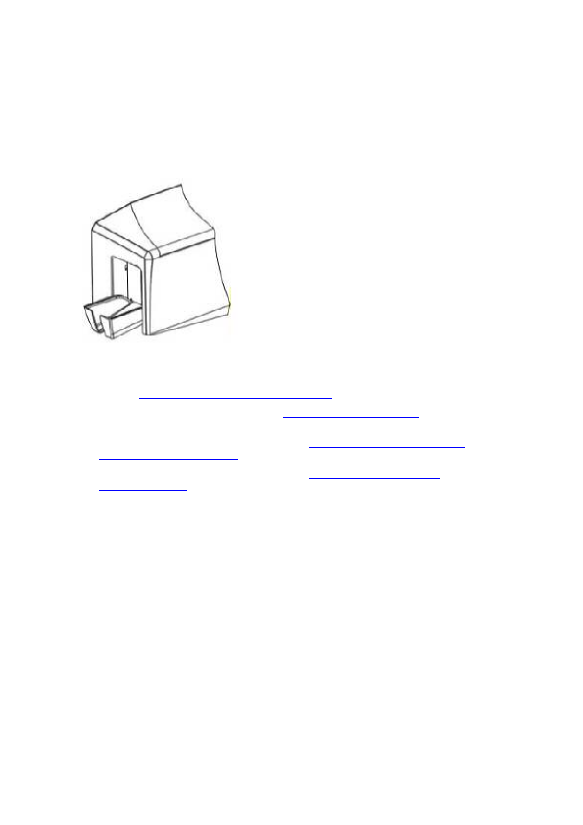
Printer Module: Flipper Table Module Assembly (D900200)
The Flipper Table Module Assembly (D900200) is an automated Flipping Module that
allows the Printer to print on the frontside and backside of each card.
Display: Flipper Table Module Assembly
Here are references within this document.
• See the Installing the Flipper Table Module Assembly (D900200)
• See the Flipper Table Module Assembly Problems
procedures.
procedure.
• See the Print Both Sides option in the Using the Device Options tab
(DTC400/DTC300) section.
• See the Front and Back radio buttons in the Using the Overlay / Print Area tab
(DTC400/DTC300/DTC300M) section.
• See the Front and Back radio buttons in the Using the K Panel Resin tab
(DTC400/DTC300) section.
• See the DTC400/DTC300/DTC300M Card Printer Service Manual for the replacement
procedures for this Printer.
DTC400/DTC300/DTC300M Card Printer Service Manual (Rev. 1.3)
Page 31

RESTRICTED USE ONLY Fargo Electronics, Inc.
3-1
Section 3: Secure Print Security Suite
Overview
SecureMark is a multi-faceted security solution that has been designed for Fargo
Electronics, our Import Suppliers, their Integrators and our Printer customers. The
SecureMark Media is the core component of the SecureMark program. Using RFID
technology, SecureMark Media raises the level of customer security and convenience.
SecureMark Media is used together with the Printer Security CD to convert a generic Fargo
Printer to a SecureMark Printer. After this conversion, the Printer will only accept Integrator
specific SecureMark media (Ribbon).
In order to enter the Fargo Secure Print Security Suite, an administrator must enter a
password and select a Printer. The Fargo Secure Print Security Suite consists of the
products listed below.
Refer to the Fargo Secure Print Security Suite User Guide for more detailed procedures.
Print Notification Application
The Print Notification Application gives the User the ability to send an e-mail to an
administrator when the Printer used during unauthorized hours.
Security Imaging Application
A Ribbon with a fluorescing panel is used to print an encrypted secure code, User-defined
text or a User-defined security graphic. The secure code can be used to produce the
Printer serial number, printing time and issue for a given card.
Print Diagnostics Application
An automated report captures Printer status and settings that can be sent to the Integrator
(or Fargo) technical support. This report can be easily e-mailed or faxed in order to
expedite faster service.
Supplies e-Ordering Application
This is an on-line Media ordering system that enables customers to order their unique
SecureMark media directly from their Integrators. When they press the order button, the
destination is their exact Ribbon on their Integrators web site.
Password Control Application
A password stored in the Printer protects a Printer from unauthorized use. Password
protection can be based on elapsed time to disable the Printer, entering a password for
each print or entering a password each day.
DTC400/DTC300/DTC300M Card Printer Service Manual (Rev. 1.3)
Page 32

RESTRICTED USE ONLY Fargo Electronics, Inc.
3-2
Print Security Suite – Main Window
Here are the icons for the five (5) applications within the Print Security Suite. See the
Functional Specification section and the Software Instructions section in this same
document for more detailed information on these five (5) applications. Caution: Be sure
and save your work in the Printer Security Suite. By selecting Save All on the File
dropdown menu, you can save your work on all active applications.
SecureMark Media
SecureMark Media is used together with the Print Security Suite to convert a generic Fargo
Printer to a SecureMark Printer. After this conversion, the Printer will only accept
Integrator-specific SecureMark media (Ribbon). The following is the basic process for
converting to SecureMark media.
a. The User installs the Print Security Suite.
b. The CD Installation process prompts the User to launch the Print Security Suite.
c. The Print Security Suite detects the SecureMark Media installed in the Printer and
prompts the User to convert the Printer to be SecureMark enabled.
d. The SecureMark conversion is completed and only Integrator specific SecureMark
media will work in this Printer.
DTC400/DTC300/DTC300M Card Printer Service Manual (Rev. 1.3)
Page 33

RESTRICTED USE ONLY Fargo Electronics, Inc.
4-1
Section 4: Setup and Installation
Procedures
The following guide will walk you through the installation of the DTC400/DTC300/DTC300M
Card Printer Driver.
• Time Requirement (software): This software installation process will require
approximately 2 to 5 minutes (depending on the speed of your PC).
• Time Requirement (Printer): The time required to set up a standard
DTC400/DTC300/DTC300M Printer would be approximately 5 to 10 minutes.
The System Requirements are as follows:
IBM-PC or compatible, Windows® 98SE, Me/2000/XP, Pentium® class 233MHz computer
with 64MB of RAM or higher, 200MB free hard disk space or higher, USB 1.1
Table of Contents
Section 4: Setup and Installation Procedures ___________________________________ 4-1
Table of Contents ___________________________________________________________________ 4-1
Printer Setup and Installation __________________________________________________________ 4-3
Choosing A Good Location _________________________________________________________ 4-3
About Moisture Condensation _______________________________________________________ 4-3
Printer Setup and Installation ___________________________________ Error! Bookmark not defined.
Choosing A Good Location __________________________________ Error! Bookmark not defined.
About Moisture Condensation ________________________________ Error! Bookmark not defined.
Unpacking and Inspection __________________________________________________________ 4-4
Reviewing the Printer (front view)____________________________________________________ 4-4
Reviewing the Printer (front view; Cartridge being installed) _______________________________ 4-5
Reviewing the LCD (top-front part of Printer)___________________________________________ 4-5
Connecting the Printer power________________________________________________________ 4-6
Installing the Print Ribbon Cartridge __________________________________________________ 4-7
Installing the Print Ribbon Cartridge (continued) ______________________________________ 4-8
Installing the Print Ribbon Cartridge (continued) ______________________________________ 4-9
Installing Blank Cards into the Card Hopper ___________________________________________ 4-10
Installing Blank Cards into the Card Hopper (continued) _______________________________ 4-11
Installing Blank Cards into the Card Hopper (continued) _______________________________ 4-12
Lowering the Card Output Hopper ___________________________________________________ 4-13
Flipper Table Module Installation______________________________________________________ 4-14
Installing the Flipper Table Module Assembly (D900200) ________________________________ 4-14
Installing the Flipper Table Module Assembly (D900200) (continued) ____________________ 4-15
Installing the Flipper Table Module Assembly (D900200) (continued) ____________________ 4-16
DTC400 Card Printer/Encoder Card Flipper Module Upgrade Kit_____________________________ 4-17
Introduction ____________________________________________________________________ 4-17
Installing the Card Flipper Module Upgrade Kit ________________________________________ 4-18
Installing the Card Flipper Module Upgrade Kit (continued) ____________________________ 4-19
Installing the Card Flipper Module Upgrade Kit (continued) ____________________________ 4-20
Installing the Card Flipper Module Upgrade Kit (continued) ____________________________ 4-21
Installing the Card Flipper Module Upgrade Kit (continued) ____________________________ 4-22
Installing the Card Flipper Module Upgrade Kit (continued) ____________________________ 4-23
Installing the Card Flipper Module Upgrade Kit (continued) ____________________________ 4-24
Installing the Card Flipper Module Upgrade Kit (continued) ____________________________ 4-25
Printer Driver Installation ____________________________________________________________ 4-26
DTC400/DTC300/DTC300M Card Printer Service Manual (Rev. 1.3)
Page 34

RESTRICTED USE ONLY Fargo Electronics, Inc.
4-2
Installing the Printer Driver ________________________________________________________ 4-26
Installing the Printer Driver (continued) ____________________________________________ 4-27
Installing the Printer Driver (continued) ____________________________________________ 4-28
Installing the Printer Driver (continued) ____________________________________________ 4-29
Installing the Printer Driver (continued) ____________________________________________ 4-30
Installing the Printer Driver (continued) ____________________________________________ 4-31
Installing the Printer Driver (continued) ____________________________________________ 4-32
Installing the Printer Driver (continued) ____________________________________________ 4-33
Installing the Printer Driver (continued) ____________________________________________ 4-34
Installing the Printer Driver (continued) ____________________________________________ 4-35
Installing the Printer Driver (continued) ____________________________________________ 4-36
Installing the Printer Driver (continued) ____________________________________________ 4-37
Installing the Printer Driver (continued) ____________________________________________ 4-38
Printing a Test Print Image_________________________________________________________ 4-39
Printing a Test Print Image (continued)_____________________________________________ 4-40
Printer Transport ___________________________________________________________________ 4-41
Moving the Printer to another location ________________________________________________ 4-41
DTC400/DTC300/DTC300M Card Printer Service Manual (Rev. 1.3)
Page 35

RESTRICTED USE ONLY Fargo Electronics, Inc.
4-3
Printer Setup and Installation
Choosing A Good Location
Follow these guidelines:
• Place the unit in a location with adequate air circulation to prevent internal heat build up.
• Use the Printer's dimensions as a guideline for the minimum clearances to the unit.
(Note: Allow for adequate clearance in front of the unit to accommodate the unit with its
Covers open.)
• Do not install unit (a) near heat sources such as radiators or air ducts or (b) in a place
subject to direct sunlight, excessive dust, mechanical vibration or shock.
About Moisture Condensation
If the unit is brought directly from a cold to a warm location or is placed in a very damp room,
moisture may condense inside the unit. Should this occur, print quality may not be optimum.
Leave the unit turned OFF in a warm, dry room for several hours before using. This will allow
the moisture to evaporate.
DTC400/DTC300/DTC300M Card Printer Service Manual (Rev. 1.3)
Page 36

RESTRICTED USE ONLY Fargo Electronics, Inc.
4-4
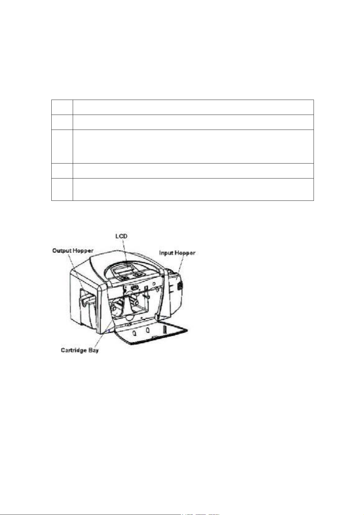
Unpacking and Inspection
While unpacking your Printer, inspect the carton to ensure that no damage has occurred
during shipping. Make sure that all supplied accessories are included with your unit.
Check that the following items are included:
• Power Supply
• US Power Cable
• Europe Power Cable
• Software Installation CD/User Guide
• User Guide
• Warranty Statement, Registration Card and Compliancy Document
Reviewing the Printer (front view)
DTC400/DTC300/DTC300M Card Printer Service Manual (Rev. 1.3)
Page 37

RESTRICTED USE ONLY Fargo Electronics, Inc.
4-5
Reviewing the Printer (front view; Cartridge being installed)
Reviewing the LCD (top-front part of Printer)
DTC400/DTC300/DTC300M Card Printer Service Manual (Rev. 1.3)
Page 38

RESTRICTED USE ONLY Fargo Electronics, Inc.
4-6
Connecting the Printer power
Follow this procedure. (Note: Do not connect the Printer’s USB cable until prompted during
the Printer Driver installation.)
Step Procedure
1 Plug the AC adapter power cable into the back of the Printer. See Display A.
2 Plug the wall power cable into the AC power adapter.
3 Plug the wall power cable into a standard 110VAC power outlet.
Display A – Shows back of Printer with AC power cable (below).
DTC400/DTC300/DTC300M Card Printer Service Manual (Rev. 1.3)
Page 39

RESTRICTED USE ONLY Fargo Electronics, Inc.
4-7
Installing the Print Ribbon Cartridge
The Fargo DTC400/DTC300/DTC300M Card Printer uses a one-piece, disposable Ribbon
Cartridge load system. Every full color Ribbon Cartridge contains a 250 “full color card count”
Ribbon and a Card Cleaning Roller.
Step Procedure
1 To install the Ribbon Cartridge, simply open the front Cover by pressing the
black rubber pad or touch pad and lowering the Cover down, as shown below.
DTC400/DTC300/DTC300M Card Printer Service Manual (Rev. 1.3)
Page 40

RESTRICTED USE ONLY Fargo Electronics, Inc.
4-8
Installing the Print Ribbon Cartridge (continued)
Step Procedure
2 a. Remove the liner on the Card Cleaning Roller before installing the Cartridge,
as shown in Display A (upper right arrow of display).
b. Remove the Ribbon securing tape, as shown in Display A (middle right arrow
of display).
3 Slide the Ribbon Cartridge into the Printer, as shown in this section.
4 Raise the front Cover and press the front Cover’s black rubber pad or touch pad
to secure it.
Display A – Shows the Print Ribbon Cartridge before it is installed or inserted into the Printer.
The Card Cleaning Roller (see arrow) is already inserted into the Print Ribbon Cartridge.
DTC400/DTC300/DTC300M Card Printer Service Manual (Rev. 1.3)
Page 41

RESTRICTED USE ONLY Fargo Electronics, Inc.
4-9
Installing the Print Ribbon Cartridge (continued)
Display B – Shows direction that Cartridge is inserted in the Printer.
DTC400/DTC300/DTC300M Card Printer Service Manual (Rev. 1.3)
Page 42

RESTRICTED USE ONLY Fargo Electronics, Inc.
4-10
Installing Blank Cards into the Card Hopper
The Fargo DTC400/DTC300/DTC300M Printer is capable of printing single load cards and
multiple feed cards (batch mode).
• To print using single feed, simply remove all cards from the Card Hopper, leave the Card
Hopper door closed and place a card in the single Feed Card Slot (which can be used
repeatedly).
• Again, the cards should be loaded with the print side down and (if applicable) the
magnetic strip up and towards the front of the Printer.
To print using Batch mode follow the instructions below.
Step Procedure
1 Open the Card Hopper Cover.
2 Press the Card Hopper Load Lever down until the Card Tray locks into place,
as shown in Display B in this section.
3 Load up to 100 cards into the Hopper with the print side down.
If using cards with a magnetic strip, the magnetic strip should be loaded with
the strip up and to the front of the Printer, as shown in Display C in this section.
4 Close the Card Hopper Cover to release the Card Tray.
Display A – This is a graphics showing how to insert the cards.
Continued on the next page
DTC400/DTC300/DTC300M Card Printer Service Manual (Rev. 1.3)
Page 43

RESTRICTED USE ONLY Fargo Electronics, Inc.
4-11
Installing Blank Cards into the Card Hopper (continued)
Display B - Press the Card Hopper Load Lever down. Insert the cards.
Here the Lever is still up.
Here the Lever is pressed down.
DTC400/DTC300/DTC300M Card Printer Service Manual (Rev. 1.3)
Page 44

RESTRICTED USE ONLY Fargo Electronics, Inc.
4-12
Installing Blank Cards into the Card Hopper (continued)
Here are the cards ready to insert.
Here the Input Hopper Door is closed.
DTC400/DTC300/DTC300M Card Printer Service Manual (Rev. 1.3)
Page 45

RESTRICTED USE ONLY Fargo Electronics, Inc.
4-13
Lowering the Card Output Hopper
Step Procedure
1 The Fargo DTC400/DTC300/DTC300M comes with a Card Output Hopper (to
hold cards after they have been printed).
Pull the Output Hopper down until it snaps into place.
DTC400/DTC300/DTC300M Card Printer Service Manual (Rev. 1.3)
Page 46

RESTRICTED USE ONLY Fargo Electronics, Inc.
4-14
Flipper Table Module Installation
Additional, related links are provided below:
• See the Flipper Table Module Assembly Problems
• See the Print Both Sides option in the Using the Device Options tab (DTC400/DTC300)
section.
• See the Front and Back radio buttons in the Using the Overlay / Print Area tab
(DTC400/DTC300/DTC300M) section.
• See the Front and Back radio buttons in the Using the K Panel Resin tab
(DTC400/DTC300) section.
procedures.
Installing the Flipper Table Module Assembly (D900200)
Step Description
1
Caution: Turn off the Printer and unplug the power cord from the
Printer.
2 Remove the Rear Cover (D90066) to the Printer.
DTC400/DTC300/DTC300M Card Printer Service Manual (Rev. 1.3)
Page 47

RESTRICTED USE ONLY Fargo Electronics, Inc.
4-15
Installing the Flipper Table Module Assembly (D900200) (continued)
Step Description
3 Remove the Card Output or Exit Door (D900092) and Left End Cap (D900064)
to the Printer, as shown below.
DTC400/DTC300/DTC300M Card Printer Service Manual (Rev. 1.3)
Page 48

RESTRICTED USE ONLY Fargo Electronics, Inc.
4-16
Installing the Flipper Table Module Assembly (D900200) (continued)
Step Description
4 a. Remove the Cover from the Flipper Table Module Assembly (D900200), as
shown below.
b. Place the Flipper Table next to Printer, as shown below.
5 Connect the Flipper Table Module cable, as shown below.
6 Slide in the Flipper Table Module pins, as shown below.
7 Attach the Flipper Table Module pin screw, as shown below.
8 Use the Torx T-10 screwdriver to attach the one (1) front Baseplate mount
screws (F000170), as shown below.
9 Attach the Flipper Table Module Cover, as shown below.
10 Connect the USB and Power cables, as shown below.
DTC400/DTC300/DTC300M Card Printer Service Manual (Rev. 1.3)
Page 49

RESTRICTED USE ONLY Fargo Electronics, Inc.
4-17
DTC400 Card Printer/Encoder Card Flipper Module
Upgrade Kit
This section provides directions on adding a Card Flipper Module to your existing DTC400
Card Printer/Encoder.
Introduction
Upgrade Kit includes:
• One (1) DTC400 Card Flipper Module
• Step-by-Step Instructional Guide
Firmware and Driver Requirements:
• Your DTC400 Card Printer/Encoder must have Firmware (Version 2.0.2 or later) and
Driver (Version 1.0.1 or later) prior to installing the Card Flipper Module.)
Tools Required:
• No. 2 Phillips Screwdriver
DTC400/DTC300/DTC300M Card Printer Service Manual (Rev. 1.3)
Page 50

RESTRICTED USE ONLY Fargo Electronics, Inc.
4-18
Printer’s Rear Cover.
Installing the Card Flipper Module Upgrade Kit
Step Procedure
1 Disconnect the Printer’s power supply.
Step Procedure
2 Use a No. 2 Phillips screwdriver to remove the screws from
(Note: Save these screws for later use in this procedure.)
DTC400/DTC300/DTC300M Card Printer Service Manual (Rev. 1.3)
Page 51

RESTRICTED USE ONLY Fargo Electronics, Inc.
4-19
Installing the Card Flipper Module Upgrade Kit (continued)
Step Procedure
3 Firmly grasp the Card Exit Hopper and pull on one side to pop out the pivot pin
from its mount hole. Next slide the other pivot pin out in order to remove the
Card Exit Hopper.
Step Procedure
4 Use a No. 2 Phillips screwdriver to remove the Printer’s Output Cover mount
screws. (Note: Save these screws for later use in this procedure.)
DTC400/DTC300/DTC300M Card Printer Service Manual (Rev. 1.3)
Page 52

RESTRICTED USE ONLY Fargo Electronics, Inc.
4-20
Installing the Card Flipper Module Upgrade Kit (continued)
Step Procedure
5 Pivot the lower end of the Output Cover in an outward motion to remove the
Output Cover.
Step Procedure
6
Use a No. 2 Phillips screwdriver to remove the Card Flipper Module Cover.
(Note: Save these screws for later use in this procedure.)
DTC400/DTC300/DTC300M Card Printer Service Manual (Rev. 1.3)
Page 53

RESTRICTED USE ONLY Fargo Electronics, Inc.
4-21
Installing the Card Flipper Module Upgrade Kit (continued)
Step Procedure
7 Place the Card Flipper Module next to the Printer.
Step Procedure
8 Connect the Card Flipper Module Communication Cable to connection J17 on
the Printer’s Main Board. (Note: The Communication Cable is “keyed” to ensure
a one-way installation.)
DTC400/DTC300/DTC300M Card Printer Service Manual (Rev. 1.3)
Page 54

RESTRICTED USE ONLY Fargo Electronics, Inc.
4-22
Installing the Card Flipper Module Upgrade Kit (continued)
Step Procedure
9 Attach the Card Flipper Module to the Printer by first sliding the rear mount pin
half way into the rear mount pin slot.
Next Slide the front mount pin into the front mount pin slot. Once the pins are
lined up with the pin slots, push the Card Flipper Module forward to fully engage
the mount pins.
DTC400/DTC300/DTC300M Card Printer Service Manual (Rev. 1.3)
Page 55

RESTRICTED USE ONLY Fargo Electronics, Inc.
4-23
Installing the Card Flipper Module Upgrade Kit (continued)
Step Procedure
10 Secure the front mount pin to the Printer by using one of the two Phillips screws
that were removed in Step 4.
Step Procedure
11 Secure the Baseplate mount by using the remaining Phillips screw that was
removed in Step 4.
DTC400/DTC300/DTC300M Card Printer Service Manual (Rev. 1.3)
Page 56

RESTRICTED USE ONLY Fargo Electronics, Inc.
4-24
Installing the Card Flipper Module Upgrade Kit (continued)
Step Procedure
12 Open the Card Flipper Module Cover’s top lid and attach its upper latch hooks to
the Printer’s top cover. Next pivot the Cover down into its final position.
Step Procedure
13 Secure the Card Flipper Cover by re-installing the two Phillips screws that were
removed in Step 6. After the Cover is secure, re-attach the Card Hopper.
DTC400/DTC300/DTC300M Card Printer Service Manual (Rev. 1.3)
Page 57

RESTRICTED USE ONLY Fargo Electronics, Inc.
4-25
Installing the Card Flipper Module Upgrade Kit (continued)
Step Procedure
14 Secure the Printer’s Rear Cover by re-installing the two Phillips screws that were
removed in Step 2.
Step Procedure
15 Connect the Printer’s Power and USB cables.
DTC400/DTC300/DTC300M Card Printer Service Manual (Rev. 1.3)
Page 58

RESTRICTED USE ONLY Fargo Electronics, Inc.
4-26
Printer Driver Installation
Installing the Printer Driver
Step Procedure
1 Close all programs and insert the Software Installation CD into your computer’s
CD drive. After a few seconds, the CD’s installer program will automatically open.
Follow the CD’s on-screen Procedures to complete installation.
(Note: If the CD does not automatically open, use My Computer or Windows
Explorer to view the contents of the CD. Then, double-click on the Setup.exe file
listed on the CD.)
2 Click on the following buttons to install the appropriate Printer Driver and Online
User’s Guide, as shown below:
• INSTALL button for the DTC400 Card Printer/Encoder
• INSTALL button for the DTC300 Card Printer/Encoder
• INSTALL button for the DTC300M Card Printer/Encoder
DTC400/DTC300/DTC300M Card Printer Service Manual (Rev. 1.3)
Page 59

RESTRICTED USE ONLY Fargo Electronics, Inc.
4-27
Installing the Printer Driver (continued)
Step Procedure
3 Wait during the installation.
DTC400/DTC300/DTC300M Card Printer Service Manual (Rev. 1.3)
Page 60

RESTRICTED USE ONLY Fargo Electronics, Inc.
4-28
Installing the Printer Driver (continued)
Step Procedure
4
Click on the Next button to continue with the Setup program.
DTC400/DTC300/DTC300M Card Printer Service Manual (Rev. 1.3)
Page 61

RESTRICTED USE ONLY Fargo Electronics, Inc.
4-29
Installing the Printer Driver (continued)
Step Procedure
Read the License Agreement. Select the I accept the terms of the license
5
agreement option and click Next to continue.
DTC400/DTC300/DTC300M Card Printer Service Manual (Rev. 1.3)
Page 62

RESTRICTED USE ONLY Fargo Electronics, Inc.
4-30
Installing the Printer Driver (continued)
Step Procedure
a. Select the Complete option to install the following components:
6
• Printer Driver Software
• Printer Driver User’s Guide
• Fargo Diagnostics Utility
(Note: Selecting Custom will provide the option to select which components to
install.)
b. Click Next to continue.
DTC400/DTC300/DTC300M Card Printer Service Manual (Rev. 1.3)
Page 63

RESTRICTED USE ONLY Fargo Electronics, Inc.
4-31
Installing the Printer Driver (continued)
Step Procedure
Click Install to begin the installation.
7
DTC400/DTC300/DTC300M Card Printer Service Manual (Rev. 1.3)
Page 64

RESTRICTED USE ONLY Fargo Electronics, Inc.
4-32
Installing the Printer Driver (continued)
Step Procedure
8 Check the appropriate checkbox to select either a single-sided or a dual-sided
printer configuration, as shown below.
DTC400/DTC300/DTC300M Card Printer Service Manual (Rev. 1.3)
Page 65

RESTRICTED USE ONLY Fargo Electronics, Inc.
4-33
Installing the Printer Driver (continued)
Step Procedure
Select the port that your Printer is connected to at this time. Click on the OK
9
button and continue with the installation.
DTC400/DTC300/DTC300M Card Printer Service Manual (Rev. 1.3)
Page 66

RESTRICTED USE ONLY Fargo Electronics, Inc.
4-34
Installing the Printer Driver (continued)
Step Procedure
10 a. Connect the USB cable to the Printer.
b. Turn ON the Printer at this time if it is not already ON.
DTC400/DTC300/DTC300M Card Printer Service Manual (Rev. 1.3)
Page 67

RESTRICTED USE ONLY Fargo Electronics, Inc.
4-35
Installing the Printer Driver (continued)
Step Procedure
11 Wait while the Driver components are being copied to your PC.
DTC400/DTC300/DTC300M Card Printer Service Manual (Rev. 1.3)
Page 68

RESTRICTED USE ONLY Fargo Electronics, Inc.
4-36
Installing the Printer Driver (continued)
Step Procedure
12
Click on the Finish button to complete the Setup, as shown below.
DTC400/DTC300/DTC300M Card Printer Service Manual (Rev. 1.3)
Page 69

RESTRICTED USE ONLY Fargo Electronics, Inc.
4-37
Installing the Printer Driver (continued)
Step Procedure
13
a. Click on the Yes button to exit the installer, as shown below.
b. Click on the No button to return to the installer’s main menu to install
additional software components.
DTC400/DTC300/DTC300M Card Printer Service Manual (Rev. 1.3)
Page 70

RESTRICTED USE ONLY Fargo Electronics, Inc.
4-38
Installing the Printer Driver (continued)
Step Procedure
14
You have completed the installation.
DTC400/DTC300/DTC300M Card Printer Service Manual (Rev. 1.3)
Page 71

RESTRICTED USE ONLY Fargo Electronics, Inc.
4-39
Printing a Test Print Image
Step Procedure
1 a. From your computer’s startup menu, select Settings > Printers and Faxes
(Windows XP) or > Printers (Windows 98SE, Me and 2000).
b. Double click on the DTC400/DTC300/DTC300M Card Printer under the
Printers window.
c. Select Printing Preferences under the Printer drop-down menu. This will bring
up the DTC400/DTC300/DTC300M Printing Preferences window.
a. Select the Card tab, and then click on the Test Print button, as shown in
2
Display A in this section. (Note: Ensure that the Ribbon is installed before
proceeding. The correct Ribbon type is selected in the Device Options
tab.)
b. When the Test Print button is selected, an image is copied to the Printer.
Display A - DTC400/DTC300/DTC300M Printer Driver Card Tab:
DTC400/DTC300/DTC300M Card Printer Service Manual (Rev. 1.3)
Page 72

RESTRICTED USE ONLY Fargo Electronics, Inc.
4-40
Printing a Test Print Image (continued)
Step Procedure
3 This completes the DTC400/DTC300/DTC300M Card Printer/Encoder Installation
Guide.
For additional help regarding the Test Print and other related items, see the
DTC400/DTC300/DTC300M Card Printer/Encoders Service Manual located under
Start > Programs > Fargo.
DTC400/DTC300/DTC300M Card Printer Service Manual (Rev. 1.3)
Page 73

RESTRICTED USE ONLY Fargo Electronics, Inc.
4-41
Printer Transport
Moving the Printer to another location
Step Procedure
1 The Printer can be transported by gripping it under the back lid, as shown in the
photo below.
2 You have completed the setup and installation procedures in this section.
DTC400/DTC300/DTC300M Card Printer Service Manual (Rev. 1.3)
Page 74

RESTRICTED USE ONLY Fargo Electronics, Inc.
5-1
Section 5: General Troubleshooting
This section provides Troubleshooting procedures for this Printer for Communication Errors,
Card Feed Errors, Print Process Errors, Card Jam Errors, Encoding Errors and Diagnosing
Image Problems.
Table of Contents
Section 5: General Troubleshooting __________________________________________5-1
Table of Contents ___________________________________________________________________ 5-1
Safety Messages (review carefully)______________________________________________________ 5-3
Communications Errors_______________________________________________________________ 5-4
Resolving the Communication Errors__________________________________________________ 5-4
Resolving the Communication Errors (continued) _____________________________________ 5-5
Print Process Errors__________________________________________________________________ 5-6
Resolving a Card Not Fed Error (Cards will not feed off the Hopper)_________________________ 5-6
Resolving a Card Not Fed Error (Cards will not feed off the Hopper) (continued)_____________ 5-7
Resolving a Card Not Fed Error (Cards will not feed off the Hopper) (continued)_____________ 5-8
Resolving a Card Not Fed Error (Two (2) or more card feed at the same time)__________________ 5-9
Resolving a Card Not Fed Error (Two (2) or more card feed at the same time) (continued)_____ 5-10
Resolving a Ribbon RFID Error (Ribbon RFID Antenna is Corrupted) ______________________ 5-11
Resolving a Ribbon RFID Error (Ribbon RFID Antenna is Corrupted) (continued) __________ 5-12
Resolving a Ribbon RFID Error (Ribbon RFID Sensor is Corrupted) ________________________ 5-13
Resolving the Mag Verify Error_____________________________________________________ 5-14
Resolving the Mag Verify Error (continued)_________________________________________ 5-15
Resolving the Mag Verify Error (continued)_________________________________________ 5-16
Resolving the No Mag Installed Error ________________________________________________ 5-17
Resolving the No Mag Installed Error (continued) ____________________________________ 5-18
Resolving a Ribbon Sensor Error (Ribbon Miscue) ______________________________________ 5-19
Resolving a Ribbon Sensor Error (Ribbon Miscue) (continued)__________________________ 5-20
Resolving a Ribbon Break Jam Error _________________________________________________ 5-21
Resolving a Ribbon Break Jam Error (continued) _____________________________________ 5-22
Resolving a Ribbon Out Error ______________________________________________________ 5-23
Resolving a No Ribbon Installed Error________________________________________________ 5-24
Resolving a No Ribbon Installed Error (continued)____________________________________ 5-25
Resolving a Invalid Ribbon Error____________________________________________________ 5-26
Resolving a Invalid Ribbon Error (continued)________________________________________ 5-27
Resolving a Wrong Ribbon Error____________________________________________________ 5-28
Resolving a Wrong Ribbon Error (continued)________________________________________ 5-29
Resolving a Card Jam Error ________________________________________________________ 5-30
Resolving a Card Jam Error (continued) ____________________________________________ 5-31
Resolving a Headlift Motor or Sensor Error____________________________________________ 5-32
Resolving a Headlift Motor or Sensor Error (continued)________________________________ 5-33
Resolving the Cover Open Error Message _____________________________________________ 5-33
Resolving the Blank Output issues___________________________________________________ 5-35
Resolving the Blank Output issues (continued)_______________________________________ 5-36
Resolving the Blank Output issues (continued)_______________________________________ 5-37
Flipper Table Module Assembly Problems_______________________________________________ 5-38
Resolving the No Flipper Table Module problem _______________________________________ 5-38
Resolving the Flipper Jam Error_____________________________________________________ 5-39
Resolving the Blank Output issues (continued)_______________________________________ 5-40
Diagnosing Image Problems __________________________________________________________ 5-41
Resolving the Pixel Failure problems_________________________________________________ 5-41
Resolving the Card Surface Debris problems___________________________________________ 5-42
Resolving the Incorrect Image Darkness problems ______________________________________ 5-43
DTC400/DTC300/DTC300M Card Printer Service Manual (Rev. 1.3)
Page 75

RESTRICTED USE ONLY Fargo Electronics, Inc.
5-2
Resolving the Incorrect Image Darkness problems (continued) __________________________ 5-44
Resolving Ribbon Wrinkle problems _________________________________________________ 5-45
Resolving Ribbon Wrinkle problems (continued) _____________________________________ 5-46
Resolving the Excessive Resin Printing problems _______________________________________ 5-47
Resolving the Excessive Resin Printing problems (continued) ___________________________ 5-48
Resolving the Incomplete Resin Printing problems ______________________________________ 5-49
Resolving the Image Placement problems _____________________________________________ 5-50
Resolving the Image Placement problems (continued) _________________________________ 5-50
Resolving the Image Placement problems (continued) _________________________________ 5-52
Resolving the Poor Image Quality problems ___________________________________________ 5-53
Running the Self Test _______________________________________________________________ 5-54
Running the Standard Self Test Print _________________________________________________ 5-55
Running the Magnetic Self Test (HiCo Only) __________________________________________ 5-56
DTC400/DTC300/DTC300M Card Printer Service Manual (Rev. 1.3)
Page 76

RESTRICTED USE ONLY Fargo Electronics, Inc.
5-3
Safety Messages (review carefully)
Symbol Critical Instructions for Safety purposes
Danger: Failure to follow these installation guidelines can result in death or
serious injury.
Information that raises potential safety issues is indicated by a warning
symbol (as shown to the left).
• To prevent personal injury, refer to the following safety messages
before performing an operation preceded by this symbol.
• To prevent personal injury, always remove the power cord prior to
performing repair procedures, unless otherwise specified.
• To prevent personal injury, make sure only qualified personnel
perform these procedures.
Caution: This device is electrostatically sensitive. It may be damaged if
exposed to static electricity discharges.
Information that raises potential electrostatic safety issues is indicated
by a warning symbol (as shown to the left).
• To prevent equipment or media damage, refer to the following
safety messages before performing an operation preceded by this
symbol.
• To prevent equipment or media damage, observe all established
Electrostatic Discharge (ESD) procedures while handling cables in
or near the Circuit Board and Printhead Assemblies.
• To prevent equipment or media damage, always wear an
appropriate personal grounding device (e.g., a high quality wrist
strap grounded to avoid potential damage).
• To prevent equipment or media damage, always remove the
Ribbon and Cards from the Printer before making any repairs,
unless otherwise specified.
• To prevent equipment or media damage, take jewelry off of
fingers and hands, as well as thoroughly clean hands to remove oil
and debris before working on the Printer.
DTC400/DTC300/DTC300M Card Printer Service Manual (Rev. 1.3)
Page 77

RESTRICTED USE ONLY Fargo Electronics, Inc.
5-4
Communications Errors
Resolving the Communication Errors
Symptom(s): Incorrect output, communications error on PC or Printer, stalling, no response
from Printer, no job printed, “paper out” error.
Step Procedure
1 Confirm that the system meets the minimum requirements, as shown here:
• IBM-PC or compatible.
™
• Windows 98SE, Me/2000/XP Pentium
MB of RAM or higher
• 200 MB free hard disk space or higher
• USB Port
2 Confirm the correct installation of the Printer Driver.
a. Close the software program and check the Printer Driver.
class 233 MHz computer with 64
b. Reboot the computer.
c. Ensure the Printer Driver is installed correctly. (Note: Especially if an
obsolete Driver was recently removed.)
d. Ensure the correct setup options within the Printer Driver are selected.
e. Confirm that the Driver is current by checking at: www.fargo.com
3 Confirm the correct installation of the Flipper Table Module Assembly.
a. Reboot the computer.
b. Ensure that the Print Both Sides option in the Printer Driver is set
correctly.
c. Verify the Flipper Table Module Assembly is functioning properly by printing
out cards in a test run.
d. If you are experiencing problems, see Resolving the No Flipper Table
Module problem.
DTC400/DTC300/DTC300M Card Printer Service Manual (Rev. 1.3)
Page 78

RESTRICTED USE ONLY Fargo Electronics, Inc.
5-5
Resolving the Communication Errors (continued)
Step Procedure
4 Determine the problem with printing from the application.
a. Print a self-test from the Printer by holding down the Pause button on
power up to ensure that the Printer (itself) is functioning properly.
b. Print the Windows test page that is located in the General tab of the Driver.
c. Use WordPad (a 2000/XP word processing program in the Accessories
Program Group).
1) Go to the File menu and select Page Setup.
2) Click on the Printer button and select the
DTC400/DTC300/DTC300M Card Printer.
3) Click OK and reset all four margins to zero. (Note: The WordPad
will automatically replace the values with its minimum margins.)
4) Open the program and type: “This is a Test.” then, go to File on the
menu bar and select Print.
5 Determine whether there is adequate hard Drive space.
(Note: A large volume of temporary files on the computer can cause
communications errors.)
a. Access the temporary files by following this process:
• Search for all folders called TEMP. Once found, clear out the contents
of the folders.
• If using Windows 98SE, Me/2000/XP, run the System Utility - Disk
Defragmenter found in the Accessories folder of the Start Menu.
• Use a disk cleanup utility (such as Disk Cleanup found in the System
Tools folder of the Start menu) or use a third party application.
DTC400/DTC300/DTC300M Card Printer Service Manual (Rev. 1.3)
Page 79

RESTRICTED USE ONLY Fargo Electronics, Inc.
5-6
Print Process Errors
All Troubleshooting procedures assume that only factory-authorized supplies are in use in
the Printer.
Resolving a Card Not Fed Error (Cards will not feed off the Hopper)
Step Procedure
1 Review the following information.
• Symptom: Cards will not feed at all.
• Printer Error State: Card is not being detected by the Card TOF Sensor 11
seconds after the initiation of a print job causing the Printer to produce an
error
• LCD Error Display: Card Not Fed
• Driver Monitor Error Display: Unable to Feed Card
I
DTC400/DTC300/DTC300M Card Printer Service Manual (Rev. 1.3)
Page 80

RESTRICTED USE ONLY Fargo Electronics, Inc.
5-7
Resolving a Card Not Fed Error (Cards will not feed off the Hopper) (continued)
Step Procedure
2 Check the card quality / loading.
a. Remove cards from the Card Hopper.
b. Ensure that the cards are not sticking together by fanning them out and then
lining them back together in a straight deck.
c. Press the Card Hopper Load Lever down until the Card Tray locks into place.
d. Load up to 100 cards into the Hopper with the print side down.
e. Close the Card Hopper Cover to release the Card Tray.
f. Press on the Resume button.
g. If the cards do not feed, continue to Step 3.
3
Press the Cancel Print button on the Driver Monitor Error Display Message.
4 Reboot the Printer by cycling the power.
5 Check the Card Feed Motor.
a. Remove all cards from the Hopper.
b. Press the Card Hopper Load Lever down until the Card Tray locks into place.
c. Using the Fargo Diagnostic utility send a test print to the Printer. See the
Using the Diagnostic Utility tabs
.
d. Gently touch the Card Hopper Feed Roller to verify that it is turning
e. If Roller is NOT turning, continue to Step 7.
f. If Roller is turning, continue to Step 6.
6 Check Hopper Tray Spring Tension.
a. Open Card Hopper Cover.
b. Using the Fargo Diagnostic utility, send a test print to the Printer. See the
Using the Diagnostic Utility tabs
.
c. When the Card Hopper Feed Roller engages, push up on the Card Hopper
Tray.
g. If the cards feed, replace the Card Hopper Lift Spring.
d. If the cards do not feed, replace the Card Hopper Feed Roller.
DTC400/DTC300/DTC300M Card Printer Service Manual (Rev. 1.3)
Page 81

RESTRICTED USE ONLY Fargo Electronics, Inc.
5-8
Resolving a Card Not Fed Error (Cards will not feed off the Hopper) (continued)
Step Procedure
7 Card Hopper Feed Roller is not turning during a print job.
a. Remove the Printer rear cover.
b. Ensure that the Card Hopper Feed Motor power cable is securely connected
to J-20 on the Printers Main Board.
c. Ensure that the Card Hopper Feed Motor power cable is securely connected
to the Card Hopper Feed Motor.
d. Use the Fargo Diagnostic utility to send a test print to the Printer. See the
Using the Diagnostic Utility tabs
e. If the Card Hopper Feed Motor is not moving, continue to Step 8.
8 Replace Card Hopper Feed Motor.
a. Replace the Card Hopper Feed Motor.
b. Use the Fargo Diagnostic utility to send a test print to the Printer. See the
Using the Diagnostic Utility tabs
.
.
c. If the Card Hopper Feed Motor does not turn, replace the Main Board.
DTC400/DTC300/DTC300M Card Printer Service Manual (Rev. 1.3)
Page 82

RESTRICTED USE ONLY Fargo Electronics, Inc.
5-9
Resolving a Card Not Fed Error (Two (2) or more card feed at the
same time)
All Troubleshooting procedures assume that only factory-authorized supplies are in use in
the Printer.
Step Procedure
1 Review the following information.
• Symptoms: Two or more cards feed at the same time causing the cards to
jam at the Card Hopper Roller. Printer is out of cards.
• Printer Error State: Card is not being detected by card TOF Sensor 11
sec after the initiation of a print job causing the Printer to produce an error
• LCD Error Display: Card Not Fed
• Driver Monitor Error Display: Unable to Feed Card
I
DTC400/DTC300/DTC300M Card Printer Service Manual (Rev. 1.3)
Page 83

RESTRICTED USE ONLY Fargo Electronics, Inc.
5-10
Resolving a Card Not Fed Error (Two (2) or more card feed at the same time)
(continued)
Step Procedure
2 Check card quality / loading.
a. Remove cards from the Card Hopper.
b. Ensure that the cards are not sticking together by fanning them out and then
lining them back together in a straight deck.
c. Press the Card Hopper Load Lever down until the Card Tray locks into place.
d. Load up to 100 cards into the Hopper with the print side down.
e. Close the Card Hopper Cover to release the Card Tray.
f. Press on the Resume button.
g. If the cards do not feed, continue to Step 3.
3
Press the Cancel Print button on the Driver Monitor Error Display Message.
4 Reboot the Printer by cycling the power.
5 Check Card Feed TOF Sensor.
a. Remove the Printers rear cover.
b. Use a digital volt meter to place the Positive lead to pin 9 of the J-4 Main
Board connection and the negative lead to pin 12 of the J-4 Main Board
connection.
• The blocked Sensor should read +4.99 vdc.
• The open Sensor should read +1.5 vdc.
c. If the Card Feed TOF Sensor does not read properly, replace the Sensor.
6 Clean the Card Feed Roller.
DTC400/DTC300/DTC300M Card Printer Service Manual (Rev. 1.3)
Page 84

RESTRICTED USE ONLY Fargo Electronics, Inc.
5-11
Resolving a Ribbon RFID Error (Ribbon RFID Antenna is Corrupted)
All Troubleshooting procedures assume that only factory-authorized supplies are in use in
the Printer.
Step Procedure
1 Review the following information.
• Symptom: Printer RFID Sensor does not detect a recognizable signal from
the Ribbon.
• Printer Error State: The Ribbon tag information is corrupted or incorrect.
• LCD Error Display: Ribbon RFID Error
• Driver Monitor Error Display: Ribbon RFID Error
DTC400/DTC300/DTC300M Card Printer Service Manual (Rev. 1.3)
Page 85

RESTRICTED USE ONLY Fargo Electronics, Inc.
5-12
Resolving a Ribbon RFID Error (Ribbon RFID Antenna is Corrupted)
(continued)
Step Procedure
2 Replace the Print Ribbon
a. Replace the Print Ribbon Cartridge.
b. Press on the Resume button.
c. If the error continues, see Resolving the Ribbon RFID Error (Ribbon RFID
Sensor is Corrupted) in this section.
DTC400/DTC300/DTC300M Card Printer Service Manual (Rev. 1.3)
Page 86

RESTRICTED USE ONLY Fargo Electronics, Inc.
5-13
Resolving a Ribbon RFID Error (Ribbon RFID Sensor is Corrupted)
All Troubleshooting procedures assume that only factory-authorized supplies are in use in
the Printer.
Step Procedure
1 Review the following information.
• Symptom: Printer RFID Sensor does not detect a recognizable signal from
the Ribbon.
• Printer Error State: The Ribbon tag information is corrupted or incorrect.
• LCD Error Display: Ribbon RFID Error
• Driver Monitor Error Display: Ribbon RFID Error
2 Replace the Print Ribbon RFID Sensor.
a. Replace the Print Ribbon RFID Sensor.
b. Press on the Resume button.
c. If the error continues, replace the Printer Main Board.
DTC400/DTC300/DTC300M Card Printer Service Manual (Rev. 1.3)
Page 87

RESTRICTED USE ONLY Fargo Electronics, Inc.
5-14
Resolving the Mag Verify Error
All Troubleshooting procedures assume that only factory-authorized supplies are in use in
the Printer.
Step Procedure
1 Review the following information.
• Symptom: The Printer is unable to verify encoded data.
• Printer Error State: The Printer is unable to verify encoded data.
• LCD Error Display: Mag Verify
• Driver Monitor Error Display: Mag Verify
DTC400/DTC300/DTC300M Card Printer Service Manual (Rev. 1.3)
Page 88

RESTRICTED USE ONLY Fargo Electronics, Inc.
5-15
Resolving the Mag Verify Error (continued)
Step Procedure
2 Check to ensure that the cards are loaded with the Magnetic Stripe facing Up
and towards the front of the Printer.
3
a. Press on the Resume button.
b. If the error continues continue to step 4
4 Verify the Driver settings if cards are loaded properly. See the Using the
Magnetic Encoding tab (DTC400/DTC300/DTC300M) procedure.
5 Verify that data is being encoded to the Magnetic Stripe.
a. Clear any Error Messages from the LCD by unplugging the Printer and
reapplying power.
b. Remove the failed card.
c. Use a Magnetic Stripe reader or magnetic developer spray to determine if
data is being written to the Magnetic Stripe.
d. If data is not being written to the Magnetic Stripe,
• Open the front cover.
• Remove the Magnetic Module cover screw.
• Remove the Magnetic Module cover.
• Verify that the Magnetic Module is seated securely into the Magnetic
Module docking station.
e. If the Magnetic Module is properly seated, replace the magnetic head (as
needed). (Note: See the current DTC400/DTC300/DTC300M Service
Manual for related instructions in the Parts Replacement Section.)
f. If data is being written to the Magnetic Stripe, the Magnetic Offset may
need to be adjusted. See the Using the Mag Top of Form Option
procedure.
6 Verify that the coercivity of the cards matches the Driver Settings.
DTC400/DTC300/DTC300M Card Printer Service Manual (Rev. 1.3)
Page 89

RESTRICTED USE ONLY Fargo Electronics, Inc.
5-16
Resolving the Mag Verify Error (continued)
DTC400/DTC300/DTC300M Card Printer Service Manual (Rev. 1.3)
Page 90

RESTRICTED USE ONLY Fargo Electronics, Inc.
5-17
Resolving the No Mag Installed Error
All Troubleshooting procedures assume that only factory-authorized supplies are in use in
the Printer.
Step Procedure
1 Review the following information.
• Symptom: There is not a Magnetic Encoder installed.
• Printer Error State: A print job with Magnetic encoding was sent with no
Magnetic encoder installed in the Printer.
• LCD Error Display: No Mag Installed
• Driver Monitor Error Display: No Mag Installed
DTC400/DTC300/DTC300M Card Printer Service Manual (Rev. 1.3)
Page 91

RESTRICTED USE ONLY Fargo Electronics, Inc.
5-18
Resolving the No Mag Installed Error (continued)
Step Procedure
2
Press the Cancel Print button on the Driver Monitor Error Display Message.
3 Reboot the Printer by cycling the power.
4 Verify that the Printer has a Magnetic Encoder installed.
a. Open the front cover.
b. Remove the Magnetic Module cover screw.
c. Remove the Magnetic Module cover.
d. Verify that the Printer has a Magnetic Module installed. (Note: If the
Printer is equipped with a Magnetic Encoder Module, ensure that it is
seated securely into the Magnetic Module docking station. If the issue
persists, replace the Magnetic Module. See the
DTC400/DTC300/DTC300M service manual for replacement procedures.)
5 If the Printer has no Magnetic Encoder Module, verify that the encoding data
was sent in error, check the appropriate software user’s manual for encoding
instructions.
DTC400/DTC300/DTC300M Card Printer Service Manual (Rev. 1.3)
Page 92

RESTRICTED USE ONLY Fargo Electronics, Inc.
5-19
Resolving a Ribbon Sensor Error (Ribbon Miscue)
All Troubleshooting procedures assume that only factory-authorized supplies are in use in
the Printer.
Step Procedure
1 Review the following information.
• Symptom: The Printer rolls through Ribbon and errors out
• Printer Error State: The Printer cannot find the next panel on the Ribbon.
• LCD Error Display: Ribbon Miscue
• Driver Monitor Error Display: Ribbon Sensor
DTC400/DTC300/DTC300M Card Printer Service Manual (Rev. 1.3)
Page 93

RESTRICTED USE ONLY Fargo Electronics, Inc.
5-20
Resolving a Ribbon Sensor Error (Ribbon Miscue) (continued)
Step Procedure
2 Open the front cover and remove the Ribbon Cartridge.
a. Check that the Ribbon is in good condition and not wrinkled or broken.
b. If Ribbon is broke or wrinkled, repair the Ribbon and wind up the take-up
roll 4-color panels past the damaged area.
3
Press on the Resume button.
If the issue persists, continue to Step 4.
4 Replace the Ribbon Cartridge.
a. Press on the Resume button.
b. If the issue persists, continue to Step 5.
5
Press the Cancel Print button on the Driver Monitor Error Display Message.
6 Reboot the Printer by cycling the power.
7 Use the Driver Calibration tab to calibrate the Ribbon Sensor.
• If the issue persists, continue to Step 8.
8 Replace the Ribbon Sensor.
DTC400/DTC300/DTC300M Card Printer Service Manual (Rev. 1.3)
Page 94

RESTRICTED USE ONLY Fargo Electronics, Inc.
5-21
Resolving a Ribbon Break Jam Error
All Troubleshooting procedures assume that only factory-authorized supplies are in use in
the Printer.
Step Procedure
1 Review the following information.
• Symptom: The Print Ribbon has become jammed or has broken in the
Printer
• Printer Error State: The Ribbon Supply Encoder Sensor has
unexpectedly stop receiving information from the Ribbon Encoder
• LCD Error Display: Ribbon BreakJam
• Driver Monitor Error Display: Ribbon BreakJam
\
DTC400/DTC300/DTC300M Card Printer Service Manual (Rev. 1.3)
Page 95

RESTRICTED USE ONLY Fargo Electronics, Inc.
5-22
Resolving a Ribbon Break Jam Error (continued)
Step Procedure
2 Open the front cover and remove the Ribbon Cartridge.
• If Ribbon is broken, continue to Step 3.
• If Ribbon is in good condition, continue to Step 6.
3 Adjust the print offset. See the Using the Print Top of Form Option procedure.
If the issue persists, continue to Step 4.
4 Repair the Ribbon and wind up the take-up roll 4 color panels past the
damaged area.
a. Press on the Resume button.
b. If the issue persists, continue to Step 5.
5 Use the Fargo Diagnostic utility to cycle the Printhead to ensure proper
printhead operation. See the Using the Diagnostic Utility tabs
procedure.
• If the Printhead does not cycle properly, see Resolving the Headlift Motor /
Sensor Error.
• If the Printhead functions properly, continue to Step 6.
6 Replace the Ribbon Cartridge.
a. Press on the Resume button.
b. If the issue persists, continue to Step 7.
7 Remove the rear cover in order to check that the Ribbon Encoder Sensor is
securely connected to the J-4 Main Board connection and to the Encoder
Sensor.
a. Press on the Resume button.
b. If the issue persists, replace the Encoder Sensor.
DTC400/DTC300/DTC300M Card Printer Service Manual (Rev. 1.3)
Page 96

RESTRICTED USE ONLY Fargo Electronics, Inc.
5-23
Resolving a Ribbon Out Error
All Troubleshooting procedures assume that only factory-authorized supplies are in use in
the Printer.
Step Procedure
1 Review the following information.
• Symptom: Printer will not print.
• Printer Error State: The Ribbon Sensor has detected the End Of Ribbon
mark
• LCD Error Display: Ribbon Out
• Driver Monitor Error Display: Ribbon Out
2 Replace the Ribbon Cartridge
a. Press on the Resume button.
DTC400/DTC300/DTC300M Card Printer Service Manual (Rev. 1.3)
Page 97

RESTRICTED USE ONLY Fargo Electronics, Inc.
5-24
Resolving a No Ribbon Installed Error
All Troubleshooting procedures assume that only factory-authorized supplies are in use in
the Printer.
Step Procedure
1 Review the following information.
• Symptom: Printer errors out as soon as it receives data from PC
• Printer Error State: The Printer RFID Sensor is not receiving a signal from
the Ribbon
• LCD Error Display: No Ribbon
• Driver Monitor Error Display: No Ribbon Installed
DTC400/DTC300/DTC300M Card Printer Service Manual (Rev. 1.3)
Page 98

RESTRICTED USE ONLY Fargo Electronics, Inc.
5-25
Resolving a No Ribbon Installed Error (continued)
Step Procedure
2 Verify that a Ribbon Cartridge is installed in the Printer.
a. Press on the Resume button.
b. If the issue persists, continue to Step 3.
3 Remove the rear cover and check that the Ribbon RFID cable is securely
connected to the Main Board (J-5) and the RFID Sensor.
• If the connections are loose, reattach them.
• Press on the Resume button.
• If the connections are good or if the issue persists, continue to Step 4.
4 Replace the Ribbon RFID Sensor.
DTC400/DTC300/DTC300M Card Printer Service Manual (Rev. 1.3)
Page 99

RESTRICTED USE ONLY Fargo Electronics, Inc.
5-26
Resolving a Invalid Ribbon Error
All Troubleshooting procedures assume that only factory-authorized supplies are in use in
the Printer.
Step Procedure
1 Review the following information.
• Symptom: Printer errors out as soon as it receives data from the PC
• Printer Error State: The Ribbon installed does not match the Printer model.
• LCD Error Display: Invalid Ribbon
• Driver Monitor Error Display: Invalid Ribbon
DTC400/DTC300/DTC300M Card Printer Service Manual (Rev. 1.3)
Page 100

RESTRICTED USE ONLY Fargo Electronics, Inc.
5-27
Resolving a Invalid Ribbon Error (continued)
Step Procedure
2 Verify that the Ribbon Cartridge installed is designed for the correct Printer
model.
3
Press on the Resume button.
If the issue persists, continue to Step 4.
4 Remove the rear cover and check that the Ribbon RFID cable is securely
connected to the Main Board (J-5) and the RFID Sensor.
• If the connections are loose, reattach
• Press on the Resume button..
• If the connections are good or if the issue persists, continue to Step 5.
5 Replace the Ribbon RFID Sensor.
DTC400/DTC300/DTC300M Card Printer Service Manual (Rev. 1.3)
 Loading...