

Page 1
Persona C16 Card Printer Service
Manual (Rev. 5.0)
Part Number: L000311
Page 2

RESTRICTED USE ONLY FARGO Electronic, Inc.
Persona C16 Card Printer Service Manual (Rev. 5.0), property of FARGO Electronics,
Incorporated
Copyright 2002, 2003, 2004, 2005, 2006 by FARGO Electronics, Incorporated. All rights
reserved. Printed in the United States of America. Exclusive permission is granted to
authorized resellers of FARGO products to reproduce and distribute this copyrighted
document to authorized FARGO customers, who have signed a “no disclosure agreement”
regarding the restricted, proprietary use of said document.
The revision number for this document will be updated to reflect changes, corrections,
updates and enhancements to this document.
Revision Control
Number
Revision 5.0 1 January 2004
These reference documents were thoroughly reviewed to provide FARGO with professional
and international standards, requirements, guidelines and models for our technical, training
and user documentation. At all times, the Copyright Protection Notice for each document
was adhered to within our FARGO documentation process. This reference to other
documents does not imply that FARGO is an ISO-certified company at this time.
• ANSI/ISO/ASQ Q9001-2000 American National Standard
Management Systems - Requirements (published by the American Society of Quality,
Quality Press, P.O. Box 3005, Milwaukee, Wisconsin 53201-3005)
• The ASQ ISO 9000:2000 Handbook
and John E. West; Second Edition; published by the American Society of Quality, Quality
Press, 600 N. Plankinton Avenue, Milwaukee, Wisconsin 53203)
• Juran's Quality Handbook
Edition, McGraw-Hill)
Any questions regarding changes, corrections, updates or enhancements to this document
should be forwarded to:
Date Document Title
Persona C16 Card Printer Service Manual
(Rev. 5.0)
, (sub-title) Quality
(editors, Charles A. Cianfrani, Joseph J. Tsiakals
(editors, Joseph M. Juran and A. Blanton Godfrey; Fifth
FARGO Electronics, Incorporated
Support Services
6533 Flying Cloud Drive
Eden Prairie, MN 55344 (USA)
(952) 941-9470
(800) 459-5636
FAX: (952) 941-7836
www.fargo.com
E-mail: sales@fargo.com
Persona C16 Card Printer Service Manual (Rev. 5.0)
ii
Page 3
RESTRICTED USE ONLY FARGO Electronic, Inc.
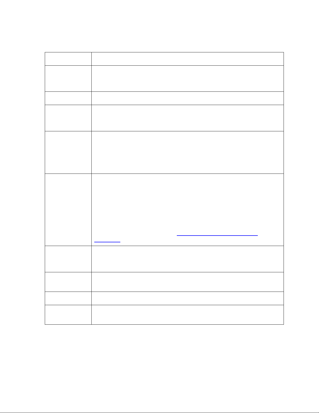
How to use the manual
The Persona C16 Card Printer Service Manual (Rev. 5.0) is, in fact, the troubleshooting
and field service manual for the entire Card Printer. The manual is designed to provide
Installers and Technicians with quick, efficient lookup of related procedures, components
and terms. The manual can be used effectively either in soft or hard copy, depending on the
preference of the Installer or Technician.
Manual Description
Sequence of Operations,
Glossary of Terms and
Technical/Functional
Specifications (hyper-linked)
Table of Contents (hyperlinked)
Troubleshooting,
Replacement, Removal,
Diagnostic and Navigation
Procedures (in hyper-linked
Sections)
Cross-Referencing (hyperlinked)
Comprehensive Index
(hyper-linked)
You can go directly to the Sequence of Operations,
Glossary of Terms, Technical Specifications and
Functional Specifications to learn how to use the
processes, procedures, functions and windows for the
Card Printer within concise, correlative tables.
You can use the Table of Contents to quickly locate an
error message, a procedure, the index or an appendix.
You can go directly to Specifications, General
Troubleshooting, Printer Adjustments, Parts Replacement,
Printer Packing, Board Level Diagnostics, LCD On-Line
Menu Navigation and Firmware Updates to find
troubleshooting, removal and replacement procedures.
The section titles are always labeled according to their
function for consistent usage.
You can use the cross-referencing links to quickly locate
an error message or a procedure.
You can use the comprehensive index to quickly locate
information on the Card Printer, relating to a specification,
a procedural step, a window or screen, a component, a
term, a qualifier or a related feature to this Printer.
Persona C16 Card Printer Service Manual (Rev. 5.0)
iii
Page 4
RESTRICTED USE ONLY FARGO Electronic, Inc.
Safety Messages (review carefully)
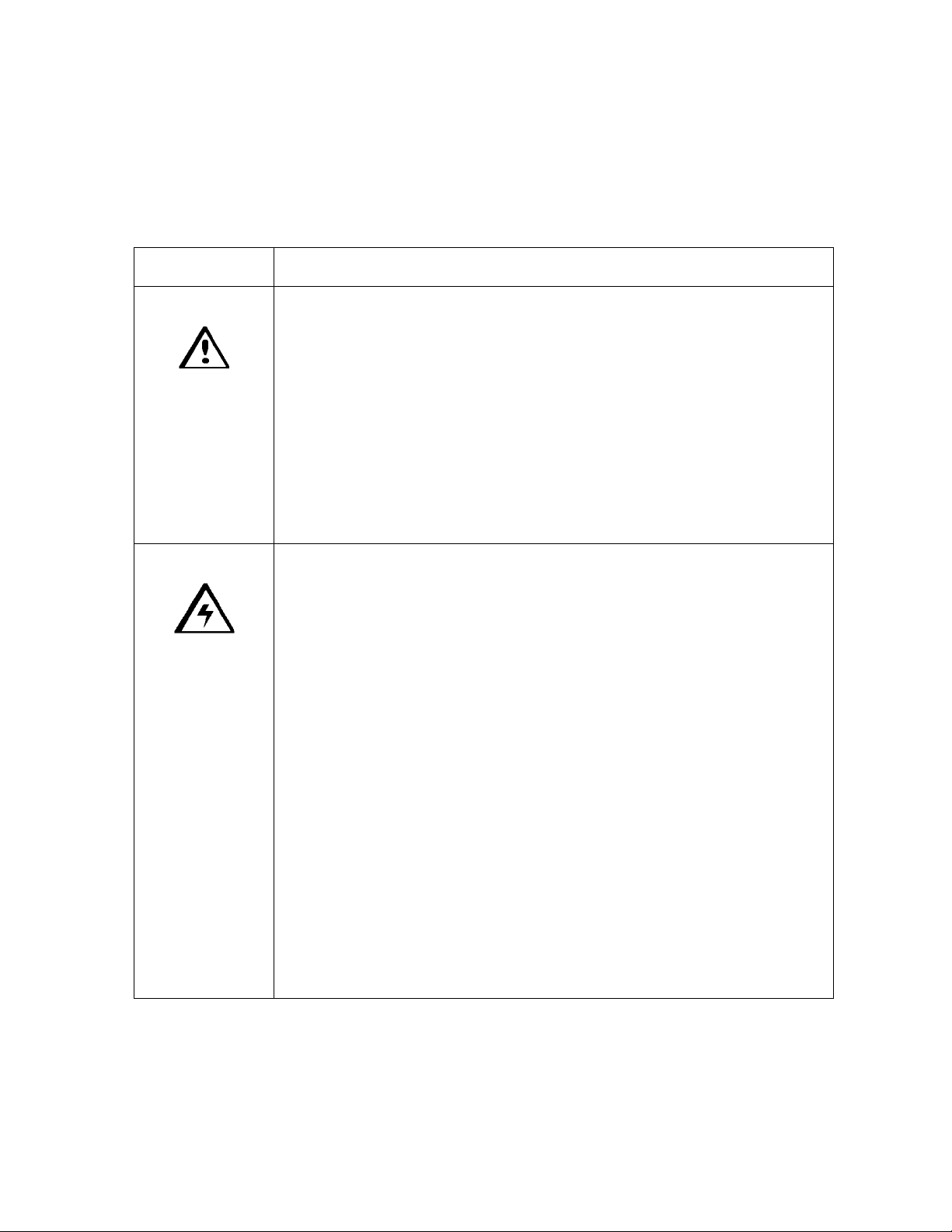
Symbol Critical Instructions for Safety purposes
Danger: Failure to follow these installation guidelines can result in death or
serious injury.
Information that raises potential safety issues is indicated by a warning
symbol (as shown to the below).
• To prevent personal injury, refer to the following safety messages
before performing an operation preceded by this symbol.
• To prevent personal injury, always remove the power cord prior to
performing repair procedures, unless otherwise specified.
• To prevent personal injury, make sure only qualified personnel
perform these procedures.
Caution: This device is electrostatically sensitive. It may be damaged if
exposed to static electricity discharges.
Information that raises potential electrostatic safety issues is indicated
by a warning symbol (as shown to the below).
• To prevent equipment or media damage, refer to the following
safety messages before performing an operation preceded by this
symbol.
• To prevent equipment or media damage, observe all established
Electrostatic Discharge (ESD) procedures while handling cables in
or near the Circuit Board and Printhead Assemblies.
• To prevent equipment or media damage, always wear an
appropriate personal grounding device (e.g., a high quality wrist
strap grounded to avoid potential damage).
• To prevent equipment or media damage, always remove the
Ribbon and Cards from the Printer before making any repairs,
unless otherwise specified.
• To prevent equipment or media damage, take jewelry off of
fingers and hands, as well as thoroughly clean hands to remove oil
and debris before working on the Printer.
Persona C16 Card Printer Service Manual (Rev. 5.0)
iv
Page 5
RESTRICTED USE ONLY FARGO Electronic, Inc.
1
9
16
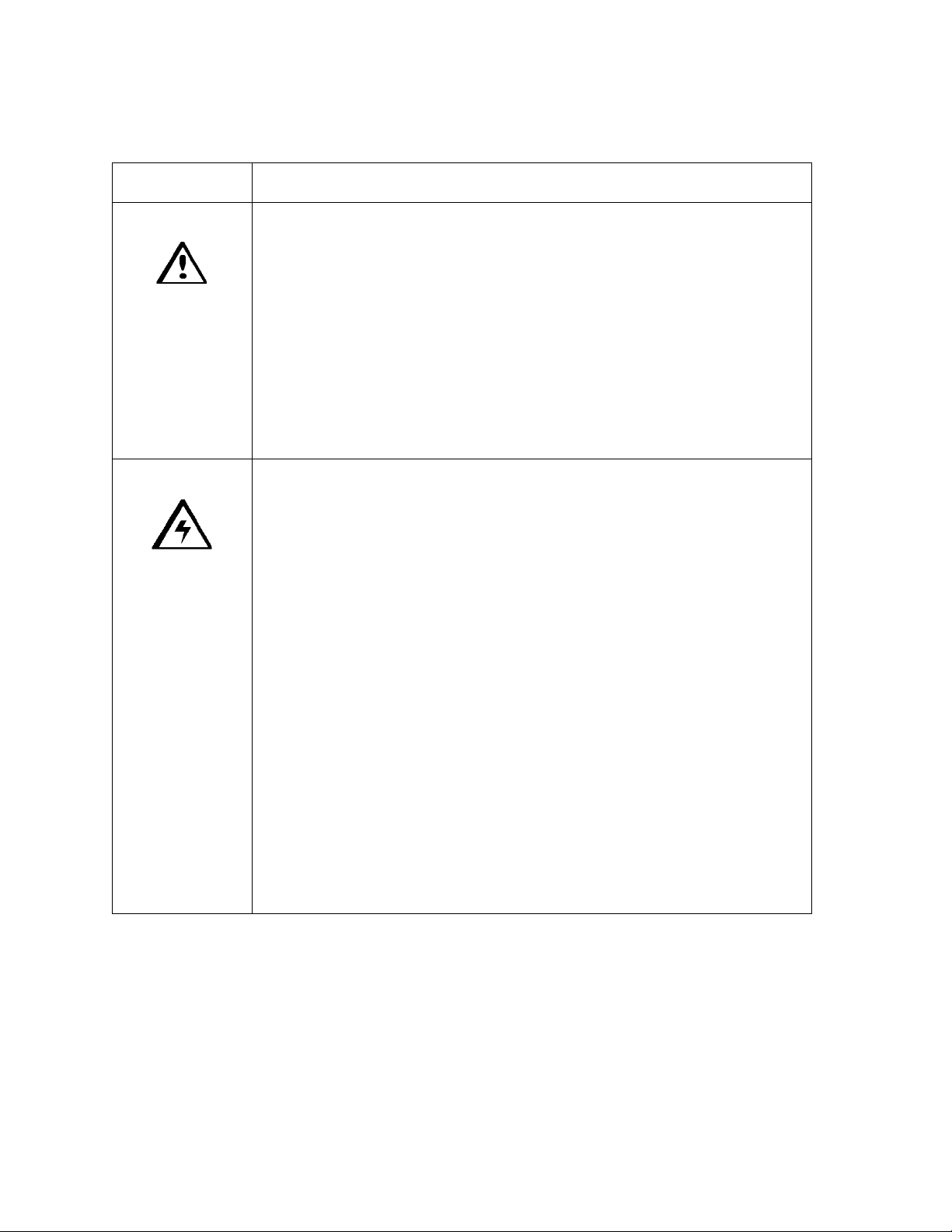
C16 Printer Overview
Reviewing the C16 Block Diagram
15
7
3
8
4
10
6
11
14 14
5
17
14
2
Motors Sensors Parts
1 Card Feed 5 Card Feed 12 Card Input Roller
2 Print Stepper 6 Ribbon Sensor 13 Cleaning Roller
3 Ribbon Drive 7 Ribbon Encoder 14 Card Feed Roller
4 Print Headlift 8 Headlift 15 Printhead Cooling Fan
9 Cover Interlock 16 Card Input Hopper
10 Printhead Thermistor 17 Magnetic Encoding Head
11 Ribbon ID
1314
12
Persona C16 Card Printer Service Manual (Rev. 5.0)
v
Page 6
RESTRICTED USE ONLY FARGO Electronic, Inc.
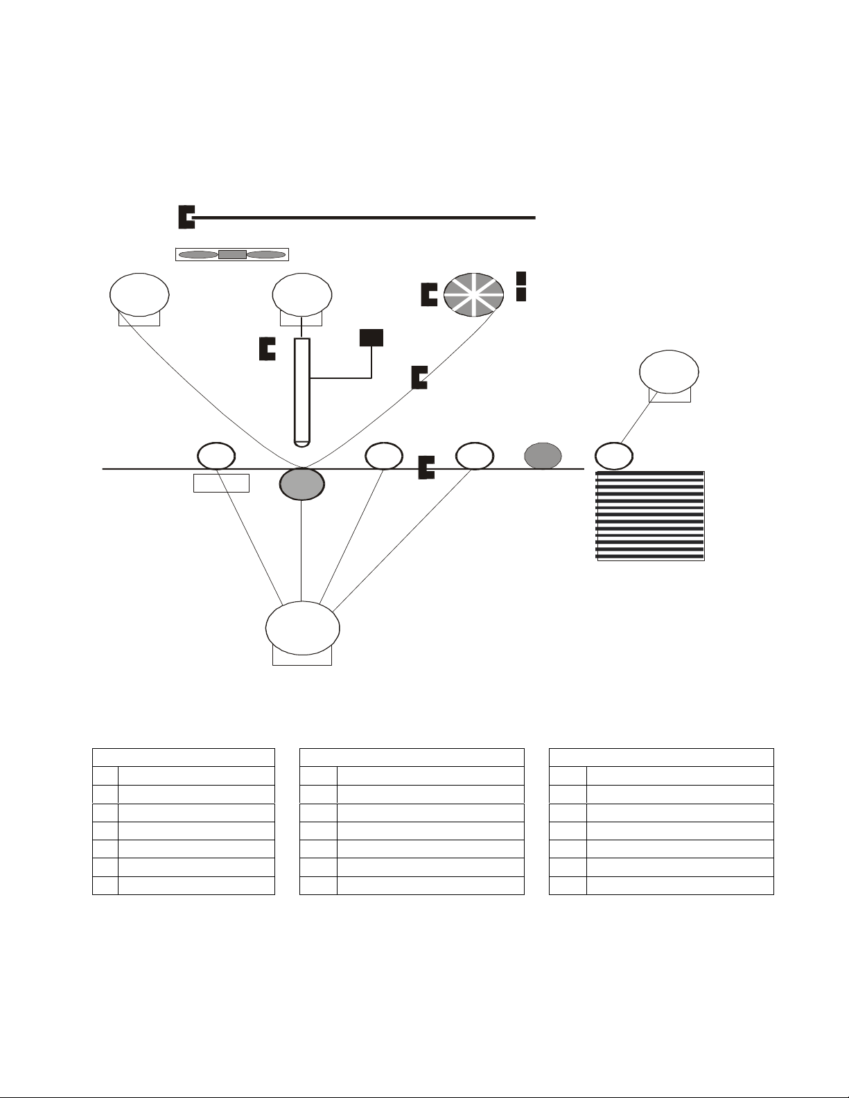
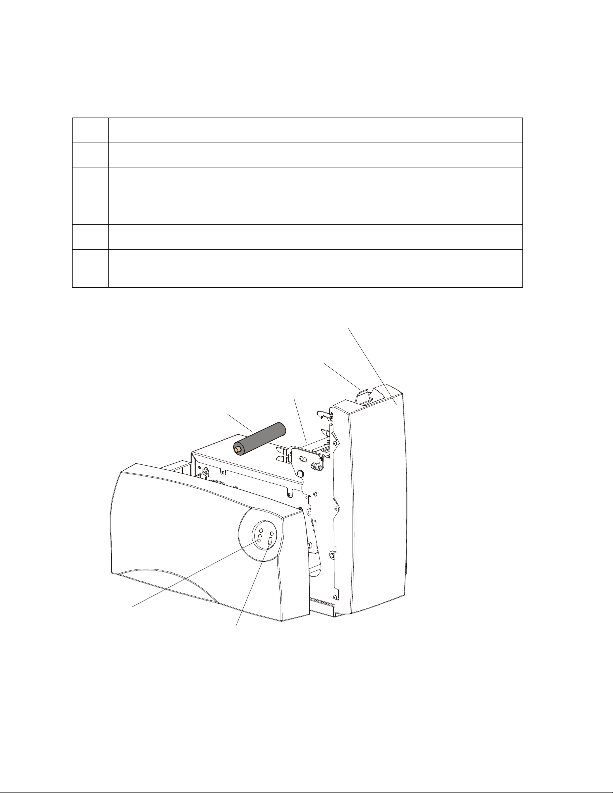
Printhead
and LED
Top Cover
Reviewing the C16 Sequence of Operations
The following sequence describes a full color print job with magnetic encoding.
Step Process
1 The File information is received from the PC
2 The Printer checks the installed Ribbon type stored in memory against the Ribbon
type command that was sent from the Printer.
a. If Ribbon type does not match, the media light will begin flashing.
3 The Card input Motor and print Stepper Motor engage.
4 The Card feed Sensor detects leading edge of card and disengages the card input
Motor.
Continued on the next page
Card Cleaning Roller
Power Button
and LED
Release Tab
Media Button
Persona C16 Card Printer Service Manual (Rev. 5.0)
vi
Page 7

RESTRICTED USE ONLY FARGO Electronic, Inc.
Reviewing the C16 Sequence of Operations (continued)
Step Process
5 The Print Ribbon Drive engages.
6 The Print Ribbon Sensor looks for the color transition from Yellow to Magenta. The
Print Ribbon Encoder detects number of revolutions required to use an entire color
panel.
7 The Print Stepper Motor engages.
8 The Card Feed Sensor detects trailing edge of card.
9 The Print Stepper Motor queues card to the middle of the platen roller. All Stop
10 The Print Headlift Motor engages.
11 The Print Headlift Sensor detects a closed state.
12 The Print Headlift Motor disengages.
13 The Print Stepper Motor engages.
14 The Print Cover Sensor checks for a closed state.
15 The Ribbon drive Motor engages.
16 The Image data is burned by the Printhead until image data is depleted. All Stop.
17 The Thermistor engages Printhead Cooling Fan to maintain proper operating
temperature.
18 The Headlift Motor engages.
19 The Print Headlift Sensor detects an open state.
20 The Print Headlift Motor disengages.
21 The Print Stepper Motor engages.
22 The Print Ribbon drive engages.
Continued on the next page
Persona C16 Card Printer Service Manual (Rev. 5.0)
vii
Page 8
RESTRICTED USE ONLY FARGO Electronic, Inc.
Reviewing the C16 Sequence of Operations (continued)
Step Process
23 After Ribbon advances a few encoder clicks, assume Ribbon free of card. All
Stop.
24 Repeat steps 9 through 23 for appropriate number of color/overlay panels.
25 The Card Feed Stepper Motor engages to queue card for magnetic encoding.
26 The Encoding data is written to the card.
27 The Card feed Stepper will requeue the card for each verification pass required.
28 The Card is ejected from the Printer.
29 All Stop.
Persona C16 Card Printer Service Manual (Rev. 5.0)
viii
Page 9

RESTRICTED USE ONLY FARGO Electronic, Inc.
Reviewing the C16 Boot up Sequence
Step Process
1 On Power up, the Printer checks the current state of the Card Feed Sensor and
the Headlift Sensor.
2 If the Headlift Sensor is found to be open, the Headlift Motor will turn until a
closed state is seen.
3 If the Card Feed Sensor is found to be blocked, the Card Feed Stepper will
engage to eject the card.
Persona C16 Card Printer Service Manual (Rev. 5.0)
ix
Page 10

RESTRICTED USE ONLY Fargo Electronics, Inc.
Table of Contents
Section 1: Specifications __________________________________________________ 6
Regulatory Compliances _________________________________________________ 6
Agency Listings ________________________________________________________ 7
Technical Specifications _________________________________________________ 8
Visual Security Solutions (Specifications)___________________________________ 10
VeriMarkTM Cards - 2-D holographic foil application_______________________ 10
Custom HoloMarkTM Cards ___________________________________________ 10
Visual Security - Card Stock Part Numbers________________________________ 10
Visual Security - Fargo Certified Overlaminates (Special Order in 50 quantity
minimum)__________________________________________________________ 10
Visual Security Card Stock - Tolerances __________________________________ 11
VeriMarkTM - Application Specifications ________________________________ 11
HoloMarkTM and Custom HoloMarkTM - Application Specifications __________ 11
Functional Specifications________________________________________________ 12
Printer Components: Top Cover to Parallel Interface Card ___________________ 13
Printer Components: Centronics-Type Parallel Interface _____________________ 14
Printer Components: Print Ribbons _____________________________________ 14
Printer Components: Resin-Only Print Ribbons____________________________ 15
Printer Components: Dye-Sublimation Print Ribbons _______________________ 16
Printer Components: Dye-Sublimation/Resin Print Ribbons __________________ 17
Printer Components: Blank Cards_______________________________________ 18
Reviewing the upgraded 81754 PVC Cards _______________________________ 19
Section 2: General Troubleshooting _______________________________________ 21
Safety Messages (review carefully) ________________________________________ 21
Reviewing the TOP Line LCD Error/Status Messages _______________________ 22
BOTH Line LCD Error/Status Messages__________________________________ 24
Communications Errors _________________________________________________ 25
Resolving the Communication Errors ____________________________________ 25
Card Feeding Errors ____________________________________________________ 28
Resolving the Card Feeding Errors ______________________________________ 28
Using the Idler Spring Upgrade Kit ______________________________________ 29
Print Process Errors ____________________________________________________ 30
Resolving a Headlift Error _____________________________________________ 30
Resolving the Cover Open Error Message_________________________________ 31
Resolving the Blank Output issues ______________________________________ 32
Card Jam Errors _______________________________________________________ 34
Resolving a Card Jam Error ____________________________________________ 34
Ribbon Errors_________________________________________________________ 35
Resolving the Skipping Ribbon Panel issues_______________________________ 35
Resolving the Wrong Ribbon error (being displayed incorrectly)_______________ 38
Resolving the Ribbon Low Message _____________________________________ 39
Resolving the Ribbon Error/Out Error Message ____________________________ 40
Resolving the Ribbon Breaking issues____________________________________ 41
Persona C16 Card Printer Service Manual (Rev. 5.0)
1
Page 11

RESTRICTED USE ONLY Fargo Electronics, Inc.
Encoding Errors _______________________________________________________ 46
Resolving the Mag Verify Error Message _________________________________ 46
Resolving the Printer’s inability to read Encoded Data_______________________ 48
Resolving Data intended for Magnetic Stripe (being printed on the card) problem _ 49
Diagnosing Image Problems _____________________________________________ 50
Resolving the Pixel Failure problems ____________________________________ 50
Resolving the Card Surface Debris problems ______________________________ 51
Resolving the Incorrect Image Darkness problems __________________________ 52
Resolving the Ribbon Wrinkle problems__________________________________ 54
Resolving the Excessive Resin Printing problems___________________________ 56
Resolving the Incomplete Resin Printing problems__________________________ 58
Resolving the Image Placement problems _________________________________ 59
Resolving the Poor Image Quality problems _______________________________ 62
Running the Self Test___________________________________________________ 63
Running the Standard Self Test Print_____________________________________ 63
Using the DIP Switch (Self-test) ________________________________________ 64
Setting the DIP Switch Settings _________________________________________ 65
Running the 15-Shade Self Test_________________________________________ 66
Interfacing Information _________________________________________________ 67
Reviewing the Pin Assignments ________________________________________ 67
Reviewing the Centronics Parallel Pin Assignments_________________________ 68
Reviewing the Printer Timing Diagram___________________________________ 71
Reviewing the Printer Timing __________________________________________ 72
Section 3: Printer Adjustments ___________________________________________ 73
Safety Messages (review carefully) ________________________________________ 73
Adjusting for CR-79 Adhesive Back Cards________________________________ 74
Adjusting the Magnetic Encoding Head __________________________________ 77
C16 Print Driver Options ________________________________________________ 78
Using the Settings dialog box ____________________________________________ 78
Using the Image Darkness option _______________________________________ 79
Using the Image Placement option ______________________________________ 79
Using the Print Length option __________________________________________ 81
Using the Magnetic Offset option _______________________________________ 82
Using the Card tab _____________________________________________________ 84
Adjusting the Card Size Option _________________________________________ 84
Adjusting the Orientation Option________________________________________ 85
Using the Copies Option ______________________________________________ 86
Using the Test Print Button ____________________________________________ 86
Using the About Button _______________________________________________ 87
Using the Device Options tab ____________________________________________ 88
Adjusting the Ribbon Type option_______________________________________ 88
Adjusting the Color matching option_____________________________________ 89
Adjusting for the Resin Dither __________________________________________ 90
Using the Rotate Image 180 Degrees option _______________________________ 91
Using the Buffer Single Card option _____________________________________ 92
Using the Disable Printing option _______________________________________ 93
Persona C16 Card Printer Service Manual (Rev. 5.0)
2
Page 12

RESTRICTED USE ONLY Fargo Electronics, Inc.
Using the Pause for Low Ribbon option __________________________________ 94
Using the Image Color tab _______________________________________________ 95
Using the Resin Heat (K) option ________________________________________ 96
Using the Color matching option and Default button ________________________ 97
Using the Calibrate tab__________________________________________________ 98
Using the Image Position Controls ______________________________________ 99
Using the Sensors Button_____________________________________________ 101
Using the Settings Button ____________________________________________ 102
Using the Magnetic Encoding tab ________________________________________ 103
Using the Magnetic Track Selection radio buttons _________________________ 104
Using the Magnetic Track Options radio buttons __________________________ 106
Using the Bit Density radio buttons_____________________________________ 107
Using the Character Size radio buttons __________________________________ 107
Reviewing the Enable MLE Support checkbox____________________________ 108
Using the ASCII Offset radio buttons ___________________________________ 109
Using the LRC Generation radio buttons_________________________________ 110
Using the Character Parity radio buttons _________________________________ 110
Using the Verification radio buttons and Retries selection ___________________ 111
Using the Shift Data Left checkbox_____________________________________ 112
Reviewing the ISO Track Locations ____________________________________ 113
Sending the Track Information ________________________________________ 114
Entering the Track Information ________________________________________ 114
Reviewing Tracks 1, 2 and 3 (in table format)_____________________________ 115
Reviewing the Track Data Note________________________________________ 115
Reviewing the ASCII Code and Character Table __________________________ 116
Using the Overlay/Print Area tab_________________________________________ 117
Using the Overlay/Print Area dropdown menu ____________________________ 118
Using the Overlay/Print Area__________________________________________ 119
Using the Defined Area Option ________________________________________ 120
Using Security Options (Visual Security Solutions) ________________________ 125
Selecting Orientation - Landscape under Card tab _________________________ 126
Selecting the Visual Security Solutions dropdown menu (A to D) _____________ 127
Selecting Orientation - Portfolio under Card tab ___________________________ 128
Selecting the Visual Security Solutions dropdown menu (E to H) _____________ 129
Selecting the VeriMark radio button ____________________________________ 130
Selecting the HoloMark radio button____________________________________ 131
Reviewing the Custom VeriMark Card (Custom Graphic in a 2D foil) _________ 132
Reviewing the Custom HoloMark Card (Custom Graphic in a 2D foil) _________ 133
Using the K Panel Resin tab_____________________________________________ 134
Selecting from the Print All Black With K Panel options ____________________ 135
Selecting the Full Card option _________________________________________ 136
Selecting the Defined Area(s) option____________________________________ 137
Selecting the Undefined Area(s) option__________________________________ 138
Selecting the Defined Area(s) function __________________________________ 139
Selecting the Print YMC under K and Print K Only options__________________ 147
Section 4: Cleaning ____________________________________________________ 148
Persona C16 Card Printer Service Manual (Rev. 5.0)
3
Page 13

RESTRICTED USE ONLY Fargo Electronics, Inc.
Safety Messages (review carefully) _______________________________________ 148
Using the Required Supplies __________________________________________ 149
Cleaning Procedures___________________________________________________ 150
Cleaning the Printhead _______________________________________________ 150
Cleaning the Card Feed and Cleaning Rollers _____________________________ 151
Cleaning the Platen Roller ____________________________________________ 153
Cleaning the Printer's Interior _________________________________________ 154
Section 5: Parts Replacement____________________________________________ 155
Safety Messages (review carefully) _______________________________________ 155
Reviewing the Printer Components _______________________________________ 156
Reviewing the Front Cover Components_________________________________ 156
Reviewing the Back End Components___________________________________ 157
Reviewing the Rear Side plate Components ______________________________ 158
Reviewing the Print Board Components _________________________________ 159
Reviewing the Print Area Components __________________________________ 160
Reviewing the Main Print Board Connections_____________________________ 161
Reviewing the Power Board Connections ________________________________ 161
Cover Removal_______________________________________________________ 162
Replacing the Rear Cover (D810054) ___________________________________ 162
Replacing the Top Cover (D810044)____________________________________ 162
Replacing the Front Cover (D810001)___________________________________ 163
Board, Interface and Printhead Replacements _______________________________ 164
Replacing the Print Circuit Board (D810059) _____________________________ 164
Replacing the Power Circuit Board (A000284)____________________________ 165
Replacing the Printhead Assembly (081524)______________________________ 166
Replacing the Printhead Harness Assembly (830162-00) ____________________ 167
Replacing the Front Panel Board Assembly (A000265) _____________________ 169
Motor and Mag Head Replacements ______________________________________ 170
Replacing the Headlift Motor Assembly (830143) _________________________ 170
Replacing the Card Feed Motor Assembly (830145) _______________________ 171
Replacing the Ribbon Drive Motor Assembly (830147) _____________________ 172
Replacing the Stepper Motor assembly (810113) __________________________ 173
Securing the current Stepper Motor Bracket and Fastener for increased belt tension174
Replacing the Magnetic Head Assembly (High-Coercivity: 810182 or Low-
Coercivity: 810182) _________________________________________________ 175
Sensor Replacement___________________________________________________ 177
Replacing the Card Sensor Assembly (830135) ___________________________ 177
Replacing the Upper Ribbon Sensor Assembly (83015111) __________________ 178
Replacing the Encoder Wheel Sensor Assembly (830149) ___________________ 180
Replacing the Lid Sensor Assembly (810174) ____________________________ 181
Replacing the Ribbon ID Sensor Board Assembly (820543) _________________ 182
Replacing the Lower Ribbon Sensor Assembly — C16 (83012612) ___________ 184
Roller Replacement ___________________________________________________ 185
Replacing the Platen Roller (D830023) __________________________________ 185
Replacing the Card Feed Roller (D830058) - Center________________________ 187
Replacing the Card Feed Roller (D830058) – Left _________________________ 189
Persona C16 Card Printer Service Manual (Rev. 5.0)
4
Page 14

RESTRICTED USE ONLY Fargo Electronics, Inc.
Replacing the Hopper Card Feed Roller (D830024) ________________________ 191
C11/C16 Idler Spring Removal and Replacement Kit Instructions_______________ 193
Technician Review - Idler Spring Replacement Kit for the C11 Card Printers without a
Magnetic Encoder or for all C16 Card Printers ____________________________ 193
Technician Review - Idler Spring Replacement Kit for the C11 Card Printers with the
Magnetic Encoder __________________________________________________ 194
Technician Review - Required Tools for both procedures ___________________ 194
Technician Review – Removal and Replacement Procedure No. 1_____________ 195
Removing and replacing the Idler Springs on the C11 Card Printers without the
Magnetic Encoder and for all C16 Card Printers___________________________ 195
Technician Review – Removal and Replacement Procedure No. 2_____________ 197
Removing and replacing the Idler Springs on the C11 Card Printers with the Magnetic
Encoder __________________________________________________________ 197
Technician Review – Photos related to Procedures No. 1 and No. 2____________ 200
Technician Review - Replacement parts for the C11 Card Printers without the
Magnetic Encoder and for all C16 Card Printers___________________________ 200
Technician Review - Replacement parts for the C11 Card Printers with the Magnetic
Encoder __________________________________________________________ 202
Section 6: Packing the Card Printer ______________________________________ 204
Section 7: Board Level Diagnostics _______________________________________ 205
Safety Messages (review carefully) _______________________________________ 205
Board Errors_________________________________________________________ 206
Resolving the EE Memory Error _______________________________________ 206
Resolving the DRAM Memory Error ___________________________________ 206
Sensor Testing _______________________________________________________ 206
Reviewing the Sensor Location and Voltages _____________________________ 207
Reviewing the Motor Voltages (when active) _____________________________ 207
Section 8: Firmware Upgrades __________________________________________ 208
Section 9: Fargo Technical Support ______________________________________ 209
Contacting Fargo Technical Support ______________________________________ 209
Reading the Serial Numbers on a Fargo printer______________________________ 210
Finding out when a Fargo Card Printer was manufactured ___________________ 210
Reviewing Example No. 1: Serial Number 80453289 ______________________ 210
Reviewing Example No. 2: Serial Number A1280224______________________ 210
Section 10: Reviewing the C16 Spare Parts List ____________________________ 211
Glossary of Terms _____________________________________________________ 219
Index ________________________________________________________________ 239
Appendix A: Engineering Drawings ______________________________________ 247
Appendix B: Technical Updates _________________________________________ 247
Appendix C: Miscellaneous _____________________________________________ 247
Persona C16 Card Printer Service Manual (Rev. 5.0)
5
Page 15

RESTRICTED USE ONLY Fargo Electronics, Inc.
Section 1: Specifications
The purpose of this section is to provide the User with specific information on the Regulatory
Compliances, Agency Listings, Technical Specifications and Functional Specifications for this
Printer.
Regulatory Compliances
Term Description
CSA The Printer manufacturer has been authorized by UL to represent
the Card Printer as CSA Certified under CSA Standard 22.2.
File Number: E145118
FCC The Card Printer complies with the requirements in Part 15 of the
FCC rules for a Class B digital device. (Note: These
requirements are designed to provide reasonable protection
against harmful interference in a residential installation.)
If equipment operation in a residential area causes unacceptable
interference to radio and TV reception, the operator is required to
take whatever steps are necessary to correct the interference.
ITS-EMC The Card Printer has been tested and complies with EN55022
Class B: 1995 and EN82082-1: 1997 standards for EMI
emissions.
(Note: Based on the above testing, the Printer manufacturer
certifies that the Card Printer complies with all current EMC
directives of the European Community and has placed the CE
mark on the Card Printer.)
License Number: J99032510
TÜV-GS The Card Printer has been tested and complies with IEC950 and
bears the TÜV-GS mark.
License Number: S9971826
UL The Card Printer is listed under UL 1950 Information Technology
Equipment.
File Number: E145118, Volume 1, Section 15
Persona C16 Card Printer Service Manual (Rev. 5.0)
6
Page 16

RESTRICTED USE ONLY Fargo Electronics, Inc.
Agency Listings
Term Description
Emissions
Standards
Safety
Standards
CE, FCC, CRC c1374, BSMI, ITS (EN 55022 Class B:1995, FCC
Class B, EN 82082-1:1997).
UL 1950, CSA C2.2 No.950-95 and TüV-GS (EN 60950 A1-A4, A11).
Persona C16 Card Printer Service Manual (Rev. 5.0)
7
Page 17
RESTRICTED USE ONLY Fargo Electronics, Inc.
Technical Specifications
Type Description
Print Method Dye-Sublimation/Resin Thermal Transfer
Resolution 300 dpi (11.8 dots/mm)
Colors Up to 16.7 million
Print Speed 30 seconds per card/120 cards per hour (YMCKO)
(Note: (): Indicates the print ribbon type and the number of ribbon panels
printed where Y=Yellow, M=Magenta, C=Cyan, K=Resin Black, B=DyeSublimation Black and O=Overlay.)
• Print speed is measured from the time a card feeds into the Printer to
the time it ejects from the Printer.
• Print speeds do not include the time needed for the PC to process the
image.
• Process time is dependent on the size of the file, the CPU, amount of
RAM and the amount of available resources at the time of the print.
Accepted
Standard
Card Sizes
Print Area CR-80 edge-to-edge 3.31” L x 2.02” W/84mm L x 51mmW
Accepted
Card
Thickness
Accepted
Card Types
CR-80 (3.375” L x 2.125” W/85.6mm L x 54mmW)
CR-79 Adhesive Back (3.303” L x 2.2125” W/83.9mm L x 52.1mmW)
0.20” (20 mil) to 0.30” (30 mil)/.5mm to .76mm
PVC or polyester cards with polished PVC finish; monochrome resin
required for straight polyester
Continued on the next page
Persona C16 Card Printer Service Manual (Rev. 5.0)
8
Page 18
RESTRICTED USE ONLY Fargo Electronics, Inc.
Technical Specifications (continued)
Type Description
Card Input
100 cards (30 mil)
Hopper
Capacity
Memory 2MB RAM
Printer
Drivers
System
Requirements
Windows 95, Windows 98, Windows Millennium, Windows NT 4.0,
Windows 2000, Windows XP
IBM-PC or compatible, Windows 95/98, Windows NT 4.0 or Windows
2000, Pentium™ class 133 MHz computer with 32 MB of RAM or higher,
200 MB free hard disk space or higher, ECP parallel port with DMA
access
Interface 8-bit Centronics-type parallel (ECP-compatible)
Operating
65° to 80° F/18° to 27° C
Temperature
Humidity 20-80% non-condensing
Dimensions 6.7” H x 13.1” W x 10.5"D/170mm H x 333mmW x 267mmD
Weight 15.2 lbs./6.9 kg
Supply
Voltage
Supply
Frequency
100-240 VAC, .6-1.3 A
50 Hz/60 Hz
Persona C16 Card Printer Service Manual (Rev. 5.0)
9
Page 19

RESTRICTED USE ONLY Fargo Electronics, Inc.
Visual Security Solutions (Specifications)
VeriMarkTM Cards - 2-D holographic foil application
VeriMarkTM Cards are a low cost, customized 2-D holographic foil application, that is made
in two steps.
• The first step is to emboss a base foil 1.9 cm (L) x 1.3 cm (H) onto the surface of a blank
white card.
• The second step is debossing a custom made dye into the surface of the base foil -
leaving a customized image, logo or text provided by the customer.
• Two separate color foils are used to contrast the impression.
End Users will be able to choose between 8 different card placements (4 - landscape) and
(4-portrait) where the VeriMarkTM can be located. When its time to print through the driver,
the End User will select the location on their organizations card design around which no
printing and overlay will be placed.
Custom HoloMarkTM Cards
A Custom HoloMark TM Card is a three-dimensional holographic image transferred to metal
foil and embossed to blank cards. The image is customer specific and the program mirrors
our holographic laminates program with a couple exceptions.
Visual Security - Card Stock Part Numbers
All Visual Security Cards will be offered on the following Fargo Card Stocks only:
• P/N# 81754 Ultra Card
• P/N# 81762 Ultra Card III with hi-coercivity magnetic stripe
• P/N# 81763 Ultra Card III
Visual Security - Fargo Certified Overlaminates (Special Order in 50
quantity minimum)
• Part No. 82255: PolyGuard 1.0 mil for HoloMarkTM and VeriMarkTM Cards, Clear
• Part No. 82256: PolyGuard 1.0 mil for HoloMarkTM and VeriMarkTM Cards, High
Resolution Globe design hologram with "Secure" micro-text
Persona C16 Card Printer Service Manual (Rev. 5.0)
10
Page 20

RESTRICTED USE ONLY Fargo Electronics, Inc.
Visual Security Card Stock - Tolerances
• Tolerance of base foil placement will equal +/- .010" from the nearest edges of the card
• Tolerance of layered foil will equal +/- .010"
VeriMarkTM - Application Specifications
VeriMarkTM foils will cover a dimensional area of 1.9 cm length x 1.3 cm height. The
exclusive areas are as follows:
• VeriMarkTM Card customers will be able to choose 1 of 8 pre-defined placements
(corners) via printer driver (4 positions) Landscape and (4 Positions) Portrait mode.
• VeriMarkTM foil placement will not interfere with card punch slots .
• Foil color base is silver; debossed impression is gold foil.
• VeriMarkTM foil placement will be located 0.4 cm from the edges of the card except for
the top two locations on portrait orientation cards (positions E & F). The foil will be
located 0.9 cm from the top of the card and 0.4 cm from the sides of the card.
HoloMarkTM and Custom HoloMarkTM - Application Specifications
HoloMarkTM and Custom HoloMarkTM foils will cover a dimensional area of 1.5 cm x 1.5
cm. The exclusive areas are as follows:
• HoloMarkTM and Custom HoloMarkTM card end-users will be able to choose 1 of 8 pre-
defined placements (corners) via printer driver (4 positions) Landscape and (4 positions)
Portrait mode.
• HoloMarkTM foil placement will not interfere with card punch slots.
• Foil Color options will be silver or gold.
• Outside edge placement of Foil impression options on card will be 0.4 cm from edge of
card.
• HoloMarkTM foil placement options will be at all four corners of card located 0.4 cm from
edge of card.
Persona C16 Card Printer Service Manual (Rev. 5.0)
11
Page 21

RESTRICTED USE ONLY Fargo Electronics, Inc.
Functional Specifications
This Card Printer utilizes two different, yet closely related printing technologies to achieve its
remarkable direct-to-card print quality for dye-sublimation and resin thermal transfer. The
Card Printer will print from any IBM-PC® or compatible running Windows® 95/98/Me,
Windows NT 4.0, Windows 2000 or Windows XP.
The following describes how each of these technologies works:
Function Description
DyeSublimation
Resin
Thermal
Transfer
Dye-Sublimation is the print method the C16 uses to produce smooth,
continuous-tone images that look truly photographic. (Note: This process
uses a dye-based ribbon roll that is partitioned by a number of consecutive
color panels.)
• The panels are grouped in a repeating series of these three process
colors along the entire length of the print ribbon: yellow, magenta and
cyan or YMC.
• The Printer always prints the yellow panel first, followed by the magenta
panel and the cyan panel. (Note: As the print ribbon passes beneath
the Printhead, hundreds of thermal elements within the Printhead heat
the dyes on the ribbon. When these dyes are heated, they diffuse into
the surface of the card. A separate pass is made for each of the three
color panels on the ribbon.)
By combining the colors of each panel and by varying the heat used to
transfer these colors, it is possible to print up to 16.7 million different
shades of color. (Note: This blends one color smoothly into the next,
producing photo-quality images with absolutely no dot pattern.)
Resin Thermal Transfer is the print method the Printer uses to print sharp
black text and crisp bar codes, which can be read by both infrared and
visible-light bar code scanners.
• Used to print ultra-fast, one-color ID cards on the C16. (Note: Like
dye-sublimation, this process uses the same thermal Printhead to
transfer color to a card from a resin-only print ribbon or the Resin Black
(K) Panel of a full color print ribbon.)
• Solid dots of resin-based ink are transferred and fused to the surface of
the card. (Note: This produces durable, saturated printing.)
Persona C16 Card Printer Service Manual (Rev. 5.0)
12
Page 22
RESTRICTED USE ONLY Fargo Electronics, Inc.
Printer Components: Top Cover to Parallel Interface Card
Components Description
Top Cover This cover opens to allow access to the Printhead, print ribbon and card
path. (Note: This cover must be closed in order for the Printer to begin
printing.)
Release tab This tab unlatches the Top Cover.
Printhead
On/Cancel
button
Pause/Resume
button
Card Cleaning
Roller
This Printer component actually does the printing. (Note: This
component is fragile and must not be bumped or touched with anything
other than a cleaning pen.)
The On/Cancel button turns the Printer ON and OFF. (Note: It also
serves to cancel the current print job and reset the Printer for the next
print job.)
If a card is left within the Printer after a print job is canceled, it will
automatically be ejected when the Printer is turned back ON.
The Pause/Resume button is used to pause the Printer during normal
operation and also to resume operation after an error condition is
cleared.
Note #1: In general, as the icon above this button indicates, errors are
related to either the ribbon or the cards. If an error occurs, the Media LED
will flash.
Note #2: The Printer must have both the Power LED and the Media LED
illuminated in order to print. See Reviewing the LCD Error/Status
Messages in section 2, page 22 for more information.
This roller automatically cleans cards for higher print quality. (Note:
Clean the Card Cleaning Roller during every ribbon change (every 250
cards) or as needed.)
Card Input
Load blank cards into this Hopper.
Hopper
Power Port This port connects to the (included) power cord.
Parallel
This port connects to a Windows PC with a parallel cable.
Interface Port
Persona C16 Card Printer Service Manual (Rev. 5.0)
13
Page 23
RESTRICTED USE ONLY Fargo Electronics, Inc.
Printer Components: Centronics-Type Parallel Interface
The Card Printer is equipped with a standard 8-bit centronics-type parallel interface port. This
communication port is the means through which the Printer receives data from the computer.
This section describes the pin assignments and signal specifications for this port.
• Parallel Interface: The Centronics-type parallel interface is the most widely used Printer
interface due to its simplicity, speed and standardization throughout the PC industry.
• Parallel Interface Connector: The Printer's parallel interface connector is a standard
36-pin Amp type with two metal-wire retaining clips and is ECP (Extended Capabilities
Port) compatible. It mates with a standard, bi-directional PC to Printer parallel cable. To
ensure optimal communications, keep the interface cable to 6 feet in length or under.
Printer Components: Print Ribbons
The Card Printer utilizes both dye-sublimation and/or resin thermal transfer methods to print
images directly onto blank cards. Since the dye-sublimation and the resin thermal transfer
print methods each provide their own unique benefits, print ribbons are available in resinonly, dye-sublimation-only and combination dye-sublimation/resin versions.
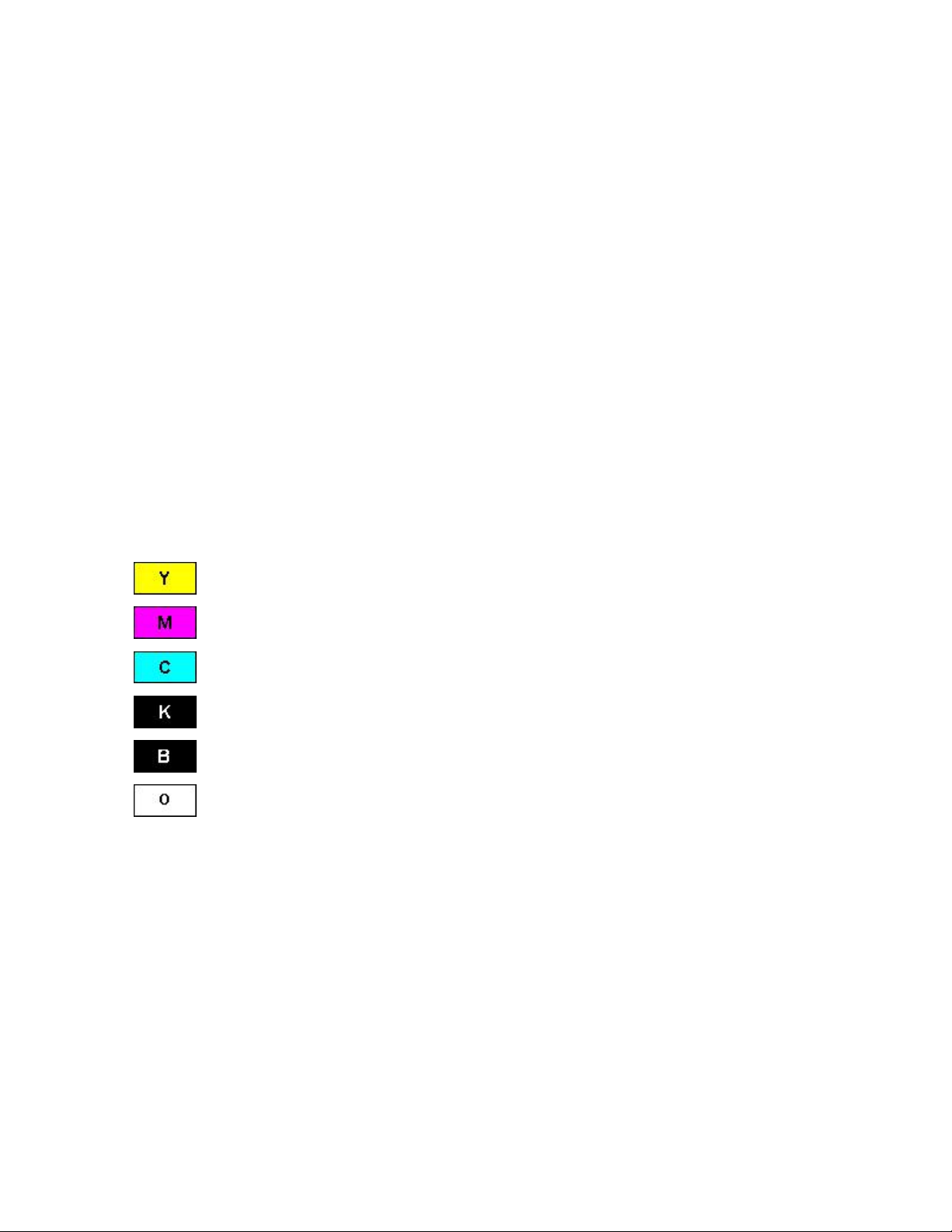
To make it easier to remember which print ribbons are which, a letter code has been
developed to indicate the type of ribbon panels found on each ribbon. This letter code is as
follows:
= Dye-Sublimation Yellow Panel
= Dye-Sublimation Magenta Panel
= Dye-Sublimation Cyan Panel
= Resin Black Panel
= Dye-Sublimation Black Panel
= Clear Protective Overlay Panel
(Note: Reference Technical Update No. 66 (dated 04/27/2003), there is a Firmware
improvement to the Persona C16 Card Printer. The ribbon-queuing improvement makes
the ribbon handling more robust to ensure the maximum number of prints from our color
ribbons.)
Persona C16 Card Printer Service Manual (Rev. 5.0)
14
Page 24
RESTRICTED USE ONLY Fargo Electronics, Inc.
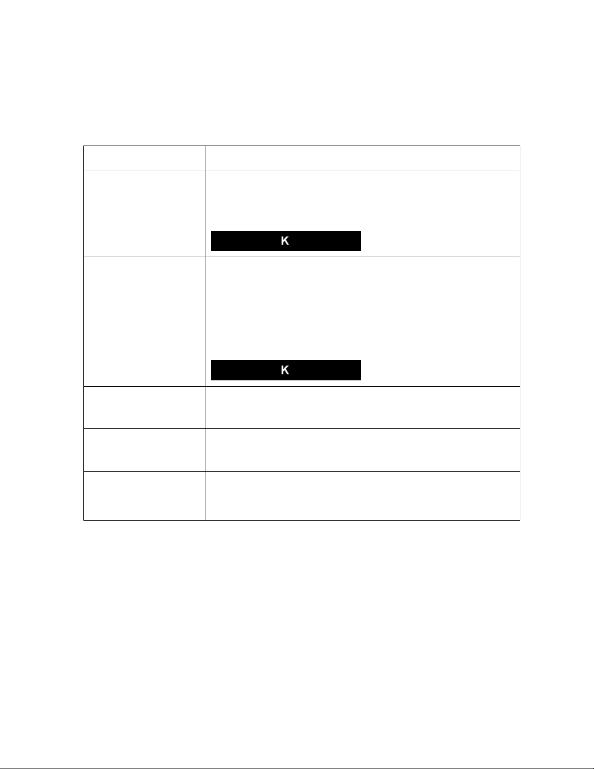
Printer Components: Resin-Only Print Ribbons
Resin-only print ribbons consist of a continuous roll of a single resin color. No protective
overlay panel (O) is provided since resin images do not require the protection of such an
overlay. The following resin-only ribbon types are available for use with the C16:
Type Description
Standard Resin Black
(K) (provides 1,000
prints)
Premium Resin Black
(K) (provides 1,000
prints)
Colored Resin
(provides 1,000 prints)
Metallic Resin
(provides 1,000 prints)
This ribbon provides high resin durability ideal for most generalpurpose monochrome ID card applications. Resin black bar
codes are readable by both infrared and visible-light bar codes
scanners.
This ribbon provides maximum resin durability ideal for
applications such as access control where cards are repeatedly
swiped through a Magnetic Stripe reader. Resin black bar codes
are readable by both infrared and visible-light bar codes
scanners.
(Note: Using a Premium Resin Black ribbon will provide better
photo realistic output.)
Several colored resin ribbons are available in a variety of colors
for customizing or color-coding resin-only ID cards.
Metallic resin ribbons are available for printing resin images with
a unique metallic sheen.
Scratch-Off Resin
(provides 1,000 prints)
Persona C16 Card Printer Service Manual (Rev. 5.0)
A scratch-off resin ribbon is available for printing over areas of a
pre-printed card in order to hide specific information such as a
personal identification number.
15
Page 25
RESTRICTED USE ONLY Fargo Electronics, Inc.
Printer Components: Dye-Sublimation Print Ribbons
The Printer requires both specialized and authorized print ribbons in order to print and
function properly.
Step Procedure
1 Do not run the cards with a contaminated, dull or uneven surface through the
Printer.
Caution: Printing onto such cards will ultimately lead to poor print
quality and will greatly reduce the life of the Printhead.
2 Always store the card stock in its original packaging or in a clean, dust-free
container.
3 Do not print onto cards that have been dropped or soiled.
Caution: Printhead damage (caused by contaminated or poor quality
cards) will automatically void the Printhead's factory warranty.
4 a. Do not print over the area of the card with the punched slot if printing onto
cards with a pre-punched slot.
b. Avoid this area when printing by using the options in the Overlay/
tab to omit printing in this area or punch the slot after the card has printed.
Continued on the next page
Print Area
Persona C16 Card Printer Service Manual (Rev. 5.0)
16
Page 26
RESTRICTED USE ONLY Fargo Electronics, Inc.
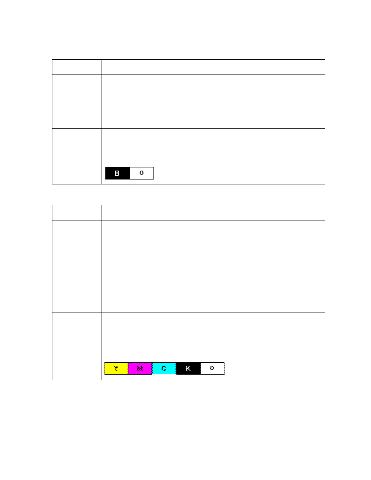
Printer Components: Dye-Sublimation Print Ribbons (continued)
Type Description
DyeSublimationOnly Print
Ribbon
DyeSublimation
Black (BO)
(provides 500
prints)
It is available in a monochrome version.
• This ribbon consists of dye-sublimation ribbon panels, which alternate
with a clear protective overlay (O) panel.
• Dye-Sublimation images must have an overlay panel applied to them
(or they will quickly begin to wear or fade).
This ribbon provides a dye-sublimation black panel (B) along with an
overlay panel (O) and is used to print smooth, photo-quality black and
white photo ID cards. (Note: Dye-Sublimation bar codes are readable
only by visible-light bar codes scanners.)
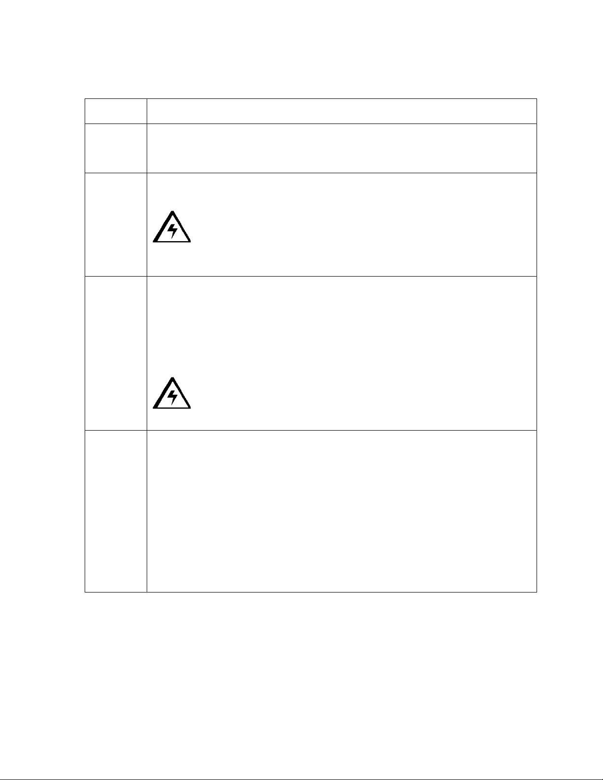
Printer Components: Dye-Sublimation/Resin Print Ribbons
Type Description
DyeSublimation/
resin print
ribbon
The Dye-Sublimation/resin print ribbon combines the yellow (Y), magenta
(M) and cyan (C) dye-sublimation panels with a Resin Black (K) Panel.
• Ribbon Panels: By combining both types of ribbon panels, this
ribbon can be used to print full-color, photo-quality images with the
dye-sublimation panels along with sharp, black text and bar codes
with the resin black panel.
• Overlay Panel: A clear overlay panel (O) is also included on most
ribbons to protect the dye-sublimation images. (Note: Dye-
Sublimation images must have an overlay panel applied to them or
they will quickly begin to wear or fade.)
Full-Color
(YMCKO)
(provides 250
prints)
Persona C16 Card Printer Service Manual (Rev. 5.0)
This ribbon is used to print full-color photo ID cards along with resin black
text and bar codes. (Note: Both infrared and visible-light bar code
scanners can read bar codes printed with resin black.)
• An overlay panel (O) is included to protect the full-color dye-
sublimation printing.
17
Page 27
RESTRICTED USE ONLY Fargo Electronics, Inc.
Printer Components: Blank Cards
Type Description
Card Size The Card Printer accepts standard CR-80 sized cards (3.370” L x 2.125”
W/85.6mm L x 54mmW) and CR-79 Adhesive Back (3.303” L x 2.2125”
W/83.9mm L x 52.1mmW) with a thickness of 20 to 30 mil.
Card
Design
Card
Surface
UltraCard
Stock
The Printer will print onto any card with a clean, level and polished PVC
surface.
Caution: Although the Printer is equipped with card cleaning rollers,
it is very important to always print onto cards specifically designed for direct-tocard dye-sublimation printing.
Cards must have a completely smooth, level surface in order for the Printer to
achieve consistent color coverage.
• Uneven Surface: Certain types of Proximity cards have an uneven
surface that will inhibit consistent color transfer.
• Raised Effect: Certain types of smart card chips are raised slightly above
the cards surface which also results in poor color transfer.
Caution: Suitable cards must have a polished PVC surface free of
fingerprints, dust or any other types of embedded contaminants.
Due to the importance of using high-quality blank cards, a factory-approved
card stock called UltraCard™ is available and recommended for best results.
(Note: UltraCard stock has a glossy PVC laminate on top and bottom and is
optically inspected to provide the cleanest, most scratch and debris-reduced
cards possible.)
Two types of these cards are available: UltraCard and UltraCard III.
• UltraCard stock has a PVC core and offers medium card durability.
• UltraCard III stock has a 40% polyester core and offers high durability.
Both types of UltraCards produce printed images with a glossy, photo-quality
finish.
Persona C16 Card Printer Service Manual (Rev. 5.0)
18
Page 28
RESTRICTED USE ONLY Fargo Electronics, Inc.
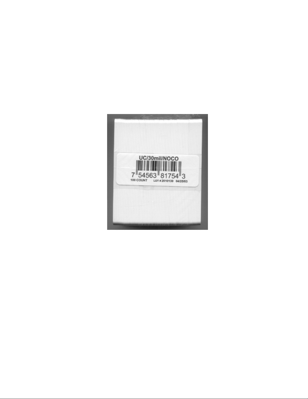
Reviewing the upgraded 81754 PVC Cards
The upgraded 81754 PVC cards are designed for a sharper card image quality and for
reduced debris and defects on Fargo Card Printers. Carefully read these detailed notes and
instructions before applying this information to your Fargo printer or printers.
• Technician Note 1: The new card lot number starts at Lot # 2010104 with date codes
that started on 04/01/2003. The photo (below) shows a lot number that starts after Lot #
2010104, indicating a new card lot number. The card lot number and date can be read
on the bar code label attached to the shrink-wrapped stack of 100 cards, as shown
below.
settings
All new Fargo printers with a serial number (S/N) starting with A320 will have factory
for these new 81754 PVC cards.
•
Technician Note 2:
printers/encoders. This same guideline is used for the existing 81754
recommends using the UltraCard III stock with the Fargo laminating printers/encoders.
Persona C16 Card Printer Service Manual (Rev. 5.0)
Do not use the new 81754 PVC card stock with Fargo laminating
PVC card stock. Fargo
19
Page 29
RESTRICTED USE ONLY Fargo Electronics, Inc.
Reviewing the upgraded 81754 PVC Cards (continued)
Follow these two (2) instructions below:
1. Instruction for new 81754 PVC card stock: Increase the Printer Driver’s Dye-Sub
Intensity to print with the new 81754 PVC card stock on Fargo Card Printers (S/N A319
and older). See the chart provided below. See the appropriate Fargo service documents
for specific Printer Driver instructions.
Card New Printer (S/N A320 and
newer)
Old Printer (S/N A319 and
older)
New Card No Change Necessary Increase the Dye-Sub Intensity as
follows:
HDP®: N/A
Pro-LX/C25: 3 - 5 %
DTC500: 5 -10 %
C11/C16: 3 - 5 %
2. Instruction for existing 81754 PVC card stock: The Printer Driver’s Dye-Sub Intensity
setting may or may not need to be decreased to print existing card stock. See the chart
provided below. See the appropriate Fargo service documents for specific Printer Driver
instructions.
• Technician Note 1: To control the brightness of the image, adjust the Dye-Sub
Intensity slide on the Image Color tab of the Printer Driver.
• Technician Note 2: Moving the Dye-Sub Intensity slide to the left causes less heat
to be used in the printing process, thus generating a lighter print.
Card New Printer (S/N A320 and
Old Printer (S/N A319 and older)
newer)
Old Card Decrease the Dye-Sub Intensity
as follows:
HDP®: N/A
Pro-LX/C25: 3 - 5 %
DTC500: 5 - 10 %
C11/C16: 3 - 5 %
Persona C16 Card Printer Service Manual (Rev. 5.0)
No Change Necessary
20
Page 30
RESTRICTED USE ONLY Fargo Electronics, Inc.
Section 2: General Troubleshooting
This section provides Troubleshooting procedures for this Printer for Communication Errors,
Card Feed Errors, Card Jam Errors, Encoding Errors and Diagnosing Image Problems.
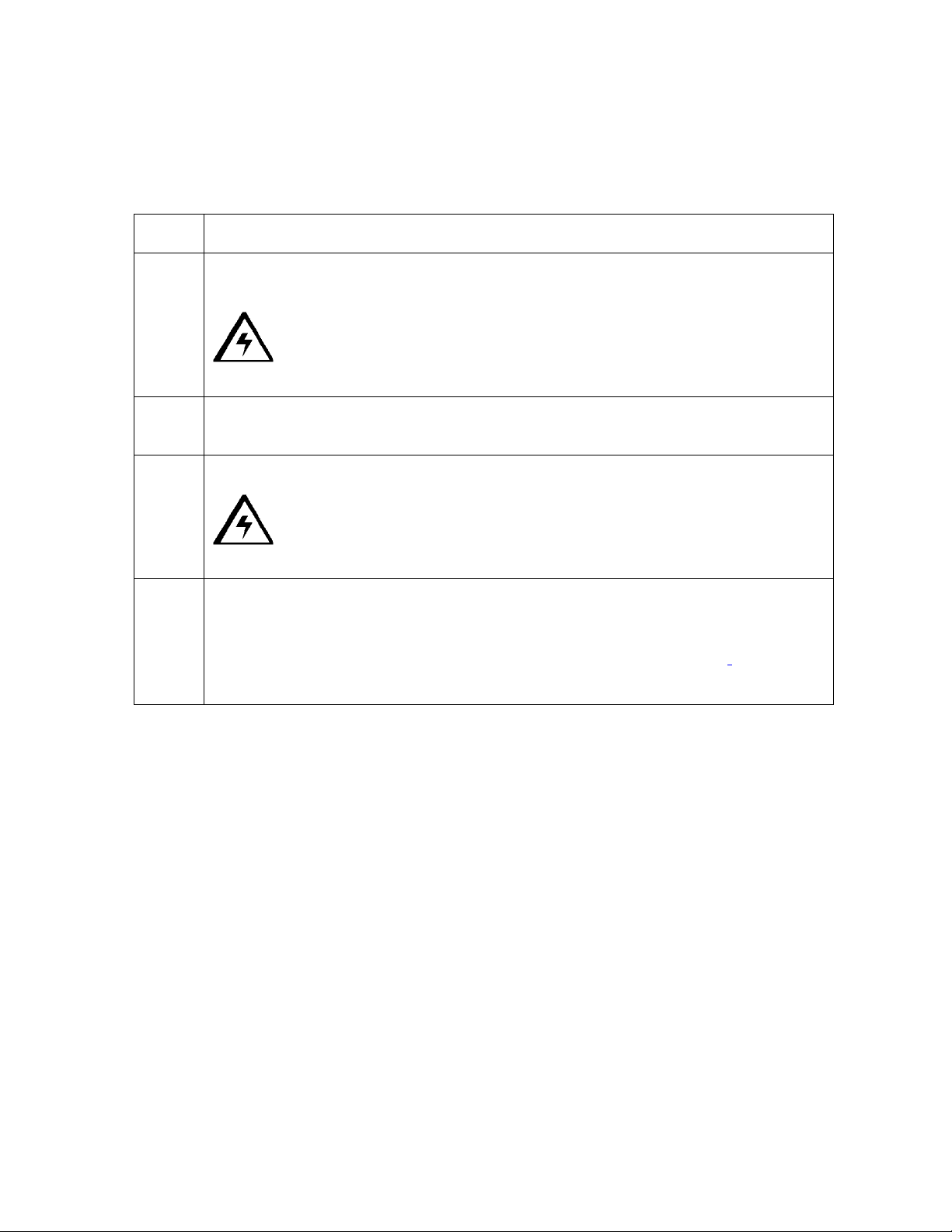
Safety Messages (review carefully)
Symbol Critical Instructions for Safety purposes
Danger: Failure to follow these installation guidelines can result in death or
serious injury.
Information that raises potential safety issues is indicated by a warning
symbol (as shown to the below).
• To prevent personal injury, refer to the following safety messages
before performing an operation preceded by this symbol.
• To prevent personal injury, always remove the power cord prior to
performing repair procedures, unless otherwise specified.
• To prevent personal injury, make sure only qualified personnel
perform these procedures.
Caution: This device is electrostatically sensitive. It may be damaged if
exposed to static electricity discharges.
Information that raises potential electrostatic safety issues is indicated
by a warning symbol (as shown to the below).
• To prevent equipment or media damage, refer to the following
safety messages before performing an operation preceded by this
symbol.
• To prevent equipment or media damage, observe all established
Electrostatic Discharge (ESD) procedures while handling cables in
or near the Circuit Board and Printhead Assemblies.
• To prevent equipment or media damage, always wear an
appropriate personal grounding device (e.g., a high quality wrist
strap grounded to avoid potential damage).
• To prevent equipment or media damage, always remove the
Ribbon and Cards from the Printer before making any repairs,
unless otherwise specified.
• To prevent equipment or media damage, take jewelry off of
fingers and hands, as well as thoroughly clean hands to remove oil
and debris before working on the Printer.
Persona C16 Card Printer Service Manual (Rev. 5.0)
21
Page 31

RESTRICTED USE ONLY Fargo Electronics, Inc.
Reviewing the TOP Line LCD Error/Status Messages
Message Cause Solution
Card Jam A card is jammed in the Printer. See the Resolving a Card Jam
Error procedure in Section 2,
page 34.
Card Out/Not Fed Either the Card Hopper is out of
cards or the Printer is unable to
feed a card in from the Card
See the Resolving the Card
Feeding Errors procedure in
Section 2, page 28.
Hopper.
Clearing Jam Indicates error or jam is being
No action required.
cleared.
Feeding Card Indicates card is feeding properly. No action required.
Head-down
Failed
Printhead is unable to lower. See the Resolving a Headlift
Error procedure in Section 2,
page 30.
Head-up Failed Printhead is unable to raise. See the Resolving a Headlift
Error procedure in Section 2,
page 30.
Low
Ribbon/Clean
Indicates the print ribbon will soon
run out and that the Printer should
be cleaned.
Print until the ribbon is gone
and replace it. Also, perform
recommended Printer
maintenance.
If this is displayed in error, see
the Resolving the Ribbon Low
Message procedure in Section
2, page 39.
Mag Encoding Indicates Mag Stripe is being
encoded.
Persona C16 Card Printer Service Manual (Rev. 5.0)
No action required.
22
Page 32

RESTRICTED USE ONLY Fargo Electronics, Inc.
Reviewing the TOP Line LCD Error/Status Messages (continued)
Message Cause Solution
Mag Verify Error The mag stripe was not encoded
properly.
See the Resolving the Mag Verify
Error Message procedure in
Section 2, page 46.
Mag Verifying Indicates data on mag stripe is
No action required.
being verified.
Print Cover Open The Top Cover is not properly
shut.
See the Resolving the Cover
Open Error Message in Section 2,
page 31.
Printer Ready Indicates Printer is ready to
No action required.
print.
Printing Indicates Printer is printing. No action required.
Rib Calib Failed The attempt at calibrating the
ribbon Sensor through the
Printer Driver has failed.
Ribbon Error/Out The print ribbon is either out or a
ribbon error has occurred.
Be sure the ribbon is removed and
that the Printer's Top Cover is
closed. Try calibrating again.
See the Resolving the Ribbon
Error/Out Error Message
procedure in Section 2, page 40.
Ribbon Jam/Out The print ribbon has become
jammed in the Printer rollers, is
stuck to the surface of the card
or is out.
Sensor Calibrate Indicates the Ribbon Sensor is
calibrating.
Wrong Ribbon The wrong print ribbon is
installed.
See the Resolving the Ribbon
Breaking issues procedure in
Section 2, page 40.
No action required.
See the Resolving the Wrong
Ribbon error (being displayed
incorrectly) procedure in Section
2, page 38.
Persona C16 Card Printer Service Manual (Rev. 5.0)
23
Page 33

RESTRICTED USE ONLY Fargo Electronics, Inc.
BOTH Line LCD Error/Status Messages
Message Cause Solution
CANCEL=Abort
RESUME=Continue
CANCEL=Abort
RESUME=Reprint
DRAM Memory
Bad!
Service Required
EE Memory Error!
RESUME=Clear
Memory
Appears when the Resume
button is pressed any time
while the Printer is powered
ON.
Also appears when the
Cancel button is pressed
during a print job.
Appears when the Cancel
button is pressed after an
error has occurred.
The Printer's 2 MB memory
module is bad or not
installed properly.
Indicates problem with
permanent circuit board
memory
Press the Resume button to return
the Printer to its Ready mode or, if
printing, to continue operation.
Press the Cancel button to abort the
current print job and completely
clear the Printer's memory.
Press the Resume button to
continue printing the current print
job where it left off, once the error is
cleared.
Press the Cancel button to abort the
current print job and completely
clear the Printer's memory.
No action required.
See the Resolving the EE Memory
Error procedure in Section 7, page
206.
EE Memory Error!
RESUME=Retest
Press ON to
initialize
Permanent circuit board
memory is bad.
Appears when the Cancel
(on/off) button is pressed
before a print job is sent,
when the Printer is in its
"Ready" mode.
Persona C16 Card Printer Service Manual (Rev. 5.0)
See the Resolving the EE Memory
Error procedure in Section 7, page
206.
Press the Cancel (on/off) button to
restart the Printer and return it to its
Ready mode.
24
Page 34

RESTRICTED USE ONLY Fargo Electronics, Inc.
Communications Errors
Resolving the Communication Errors
Symptom(s): Incorrect output, communications error on PC or Printer, stalling, no response
from Printer, no job printed, “paper out” error.
Step Procedure
1 Confirm that the system meets the minimum requirements, as shown here:
• IBM-PC or compatible.
™
• Windows 95/98/ME/NT/2000/XP Pentium
MB of RAM or higher
• 200 MB free hard disk space or higher
• ECP parallel port with DMA access
2 Confirm the correct installation of the Printer Driver.
class 133 MHz computer with 32
a. Close the software program and check the Printer Driver.
b. Reboot the computer.
Caution: Make sure the Printer Driver is installed correctly.
c. Be sure the correct Setup options within the Printer Driver are selected.
d. Confirm that the Driver is current by checking at: www.fargo.com
Continued on the next page
Persona C16 Card Printer Service Manual (Rev. 5.0)
25
Page 35

RESTRICTED USE ONLY Fargo Electronics, Inc.
Resolving the Communication Errors (continued)
Step Procedure
3 Verify the use of an adequate data cable.
a. Use a double-shielded parallel cable (no longer than six feet in length).
(Note: Data transmission failure can be attributed to a long or faulty parallel
cable.)
b. Use a double-shielded, I-EEE 1284 compliant cable to reduce the effect of
radio emissions from computers, monitors and other equipment that may
broadcast Radio frequency interference (RFI).
4 Determine if there is interference from an external device.
a. Do not use an A/B Switch Box or other peripheral in line with the parallel
cable.
b. If using a Switch Box or other peripheral, remove it while testing
communication between the Computer and the Printer.
c. If needed, replace the Switch Box or other peripheral (once it is determined
that the cause of the interference is not the switch box or peripheral).
d. Alternative: Add a second parallel port into the computer (if a second
Printer is required).
5 Determine the problem with printing from the application.
a. Print a Self-Test from the Printer by holding down the Pause/Resume button
on power up to ensure that the Printer (itself) is functioning properly.
b. Print the Windows test page that is located in the General tab of the driver.
c. Use WordPad (a Windows 95/ 98/ ME/ NT/ 2000/XP word processing
program in the Accessories Program Group) via Start > Programs >
Accessories > Wordpad on your desktop. Follow this procedure:
1) Go to the File menu and select Page Setup.
2) Click on the Printer button and select the C16 Card Printer.
3) Click on OK and reset all four margins to zero. (Note: The WordPad will
automatically replace the values with it’s minimum margins.)
4) Open the program and type: This is a Test. Go to File on the Menu Bar
and select Print.
Continued on the next page
Persona C16 Card Printer Service Manual (Rev. 5.0)
26
Page 36

RESTRICTED USE ONLY Fargo Electronics, Inc.
Resolving the Communication Errors (continued)
Step Procedure
6 Determine if the Parallel Port mode is set correctly or incorrectly
a. Ensure that the parallel port is set to the Enhanced Communication Port
(ECP) mode. (Note: The port mode can be determined by checking the
Device Manager tab in the system control panel.)
b. Change the computer’s BIOS if the port mode is not set to ECP. (Note:
Refer to the appropriate computer manual for instructions on how to change
the Parallel Port mode.)
7 Determine whether there is adequate hard drive space.
(Note: A large volume of temporary files on the computer can cause
communications errors.)
a. Access the temporary files by following this process:
• Search for all folders called TEMP. Once found, clear out the contents of
the folders.
• Run the System Utility - Disk Defragmenter (found in the Accessories
folder of the Start Menu) when using Windows 95/98/ME/2000/XP,
• Use a disk cleanup utility (such as Disk Cleanup found in the System
Tools folder of the Start menu) or use a third party application.
Persona C16 Card Printer Service Manual (Rev. 5.0)
27
Page 37
RESTRICTED USE ONLY Fargo Electronics, Inc.
Card Feeding Errors
Resolving the Card Feeding Errors
Symptom: Two or more cards feed at the same time or the cards will not feed at all.
Step Procedure
Clean the Input Roller.
Caution: Turn off the Printer and unplug the power cord from the
Printer.
a. Remove all cards from the Printer's Card Input Hopper.
b. Get a Cleaning Card from the Printer Cleaning Kit and remove its adhesive
backing paper.
c. Insert the Cleaning Card into the card output end of the Printer until the card
stops.
Caution: Be sure to insert the card so that the longest end of the card
is inserted first with the sticky side facing up.)
d. Press and hold the Printer's Pause/Resume button while applying power to
start a self-test. (Note: This will begin feeding the Cleaning Card into the
Printer.)
When the Printer errors out, open the top cover and use the Pause/Resume
button to remove the cleaning card.
2 Adjust the Card Separator Flap.
a. Loosen the two (2) screws located in the Input Hopper.
b. Open the Top Cover and remove the Print Ribbon from the Printer.
• Tighten the adjustment screws on both sides of the Card Separator Flap
to raise the card separator.
• Loosen the adjustment screws on both sides of the Card Separator Flap
to lower the card separator.
Persona C16 Card Printer Service Manual (Rev. 5.0)
28
Page 38

RESTRICTED USE ONLY Fargo Electronics, Inc.
Using the Idler Spring Upgrade Kit
The purpose of Technical Update No. 45 was to announce the release of the Idler Spring
Upgrade Kit for the Persona C11, M11 and C16 Card Printers.
• Improvement: The new Idler Spring Upgrade Kit provides more reliability when feeding
cards through the Card Printer. (Technician Note: The previous Idler Springs were
prone to breaking at an approximate output of 1000 cards.)
• Order No. 1 (without Magnetic Encoder): If using the Persona C11, M11 or C16 Card
Printer without a Magnetic Encoder installed order Part Number 085690.
OR
Order No. 2 (with Magnetic Encoder): If using the Persona C11, M11 or C16 Card Printer
with a Magnetic Encoder installed order Part Number 085691.
Persona C16 Card Printer Service Manual (Rev. 5.0)
29
Page 39

RESTRICTED USE ONLY Fargo Electronics, Inc.
Print Process Errors
Resolving a Headlift Error
Symptom: The Printhead continuously cycles or does not cycle at all.
Step Procedure
1 Cycle the Headlift Motor.
a. Press both buttons on the front control panel.
b. Verify that the Headlift Motor turns.
• If the Motor does not turn, continue to Step 2.
2 Test the Headlift Motor.
a. Unplug the Printer.
b. Remove the back cover.
c. Disconnect the Headlift Motor from the Main Board.
d. Connect a 9-volt battery to the Head Motor.
• If the Motor does not turn, replace it. See the Replacing the Headlift
Motor Assembly (830143) in Section 5, page 170.
• If the Motor does turn, continue to Step 3.
3 Test the Headlift Sensor.
a. Remove the back cover.
b. Attach the positive lead from a Digital Voltmeter to Pin 1 of J6. Attach the
negative lead to the Pin 3 of J6.
• If open, the Sensor should read 0.17 to 0.9 VDC.
• If closed, the Sensor should read 4.9 to 5.5 VDC.
c. Replace the Sensor if the voltages do not read correctly. See the Replacing
the Printhead Harness Assembly (830162-00) procedure in Section 5, page
167.
Persona C16 Card Printer Service Manual (Rev. 5.0)
30
Page 40

RESTRICTED USE ONLY Fargo Electronics, Inc.
Resolving the Cover Open Error Message
Symptom: The Printer errors immediately after sending a print job or the rollers do not
operate by pressing the cottons on the front panel (when the cover is open).
Step Procedure
1 Reseat the Cover Switch.
a. Open the top cover and remove the Print Ribbon.
b. Remove the two screws from the Cover Switch located near the ribbon take
up hub.
c. Reseat the switch on the Printer side plate and carefully replace the screws.
d. Ensure that the screws holding the Cover Sensor in place are not so tight as
to compress the inner components of the switch. (Note: The screws should
be tight enough to hold the switch in place snugly.)
Persona C16 Card Printer Service Manual (Rev. 5.0)
31
Page 41

RESTRICTED USE ONLY Fargo Electronics, Inc.
Resolving the Blank Output issues
Symptom: A card is ejected blank (that should be printed).
Step Procedure
1 Run a Self-Test.
a. Clear any Card jams.
b. Unplug the power from the Printer.
c. While holding down the Pause/Resume button, reapply power. (Note: A
self-test card will be printed.)
2 Look for an image on the Ribbon.
a. Open the top cover after a Self-Test has been run.
b. Remove the Print Ribbon from the Printer.
c. Visually inspect the set of panels (that were last used by the Printer).
• If an image is noticeable on the used ribbon, continue to step 3.
• If an image is not noticeable on the used ribbon, continue to step 4.
3 Adjust the placement.
a. Reset the Printer to clear any Error Messages by removing the power and
reapplying it.
b. Open the Printer Control Panel from the Computer.
• If using Windows 95/98/ME, right click on the C11_C16 Card Printer Icon
and select Properties.
• If using Windows NT 4.0, right click on the C11_C16 Card Printer and
select Document Defaults.
• If using Windows 2000/XP, right click on the C11_C16 Card Printer and
select Printing Preferences.
c. Click the Calibrate tab.
d. Click on the Settings button.
e. Adjust the Image Placement setting by +5.
f. Click on the OK button.
g. Print a Self-Test.
h. After adjusting the Image Placement, if a white border appears on the card,
adjust the image placement back toward its original value in increments of 2
until the white edge is gone.
Persona C16 Card Printer Service Manual (Rev. 5.0)
Continued on the next page
32
Page 42

RESTRICTED USE ONLY Fargo Electronics, Inc.
Resolving the Blank Output issues (continued)
Step Procedure
4 Check the Printhead connections.
a. Open the top print cover.
b. Remove the two (2) thumbscrews from the Printhead cover plate and remove
the cover plate.
c. Check to ensure that Power and Data Cables (that connect to the printhead)
are properly seated.
d. Remove the Back Cover.
• Ensure that the Printhead Power Cable is properly seated on J11 on the
Power board.
• Ensure that the Printhead Data Cable is properly seated on J13 on the
main board.
5 Ensure that the proper voltage is being applied to the Printhead.
a. Remove the back cover.
b. Using a Digital Voltmeter, connect the negative lead to ground.
c. Probe the Pins 1 to 5 of the Printhead power connection on J11.
d. Ensure that a voltage between 22 to 23 VDC is read on each pin.
• If less than 22 volts is read on any of the pins, ensure that the Power
Supply for the Printer is outputting 23 to 24 VDC.
• If 22 to 23 volts is read from Pins 1 to 5 on J11, replace the Printhead (as
needed). See the Replacing the Printhead Assembly (820199)
in Section
5, page 166.
e. If the Power Supply is operating properly, replace the Main Board (as
needed). See the Replacing the Front Panel Board Assembly (A000265)
Section 5, page 169.
in
Persona C16 Card Printer Service Manual (Rev. 5.0)
33
Page 43

RESTRICTED USE ONLY Fargo Electronics, Inc.
Card Jam Errors
Resolving a Card Jam Error
Symptoms: The card is physically jammed in the Printer or a Card Sensor is reporting a
card is present.
Step Procedure
1 Look for a jammed card in the Printer.
a. Open the Printer’s top cover.
b. Remove the ribbon from the Printer.
c. Check to see if a card is jammed in the print station of the Printer.
• If a card is found in the print station, continue to Step 2.
• If no card was found in the print station, continue to Step 3.
2 Clearing a jammed card
a. If a card is jammed in the Printer, use the On/Cancel button and the
Pause/Resume buttons to move the feed rollers and free the card.
b. The card can then be fed out of the Printer.
3 Test the Card Sensor.
a. Remove the rear cover.
b. Using a Digital Voltmeter, connect the negative lead to ground.
c. Connect the positive lead to Pin 1 of J8.
• If blocked, the voltage should read 4.9 to 5.5 VDC.
• If unblocked, the Sensor should read 0.15 to 0.18 VDC.
d. If the voltages do not read correctly, replace the Sensor. See the the
Replacing the Card Sensor Assembly (830135)
177.
procedure in Section 5, page
Persona C16 Card Printer Service Manual (Rev. 5.0)
34
Page 44

RESTRICTED USE ONLY Fargo Electronics, Inc.
Ribbon Errors
Resolving the Skipping Ribbon Panel issues
Symptom: The Printer is using more than one set of ribbon panels to print one side of a
card.
Step Procedure
1 Calibrate the Ribbon Sensor. (See the next page.)
a. Reset the Printer to clear any Error Messages by removing Power and
reapplying.
b. Open the Printer Control Panel from the Computer.
• If using Windows 95/98/ME, right click on the C11_C16 Card Printer
Icon and select Properties.
• If using Windows NT 4.0, right click on the C11_C16 Card Printer
and select Document Defaults.
• If using Windows 2000/XP, right click on the C11_C16 Card Printer
and select Printing Preferences. Click on the Calibrate tab.
c. Click on the Sensors button. (See the next page.)
d. Remove the ribbon and close the top cover.
e. Click on the Send button for a ribbon Sensor calibration.
f. Verify that the Printer beeps twice.
g. If the Printer does not beep twice, see Communications Errors
2, Page 22.
Continued on the next page
in Section
Persona C16 Card Printer Service Manual (Rev. 5.0)
35
Page 45

RESTRICTED USE ONLY Fargo Electronics, Inc.
Resolving the Skipping Ribbon Panel issues (continued)
See the previous procedure in this section.
Persona C16 Card Printer Service Manual (Rev. 5.0)
Continued on the next page
36
Page 46

RESTRICTED USE ONLY Fargo Electronics, Inc.
Resolving the Skipping Ribbon Panel issues (continued)
Step Procedure
2 Test the Encoder Sensor.
a. Remove the back cover.
b. Using a Digital Voltmeter, connect the negative lead to ground.
c. Connect the positive lead to Pin 4 of J13.
• If blocked, the voltage should read 4.9 to 5.5 volts DC.
• If unblocked, the Sensor should read 0.15 to 0.18 volts DC.
d. If the voltages are not correct, replace the Sensor. See the Replacing the
Encoder Wheel Sensor Assembly (830149) procedure in Section 5, page
180.
Persona C16 Card Printer Service Manual (Rev. 5.0)
37
Page 47

RESTRICTED USE ONLY Fargo Electronics, Inc.
Resolving the Wrong Ribbon error (being displayed incorrectly)
Symptom: A Wrong Ribbon Error is shown on the LCD even though the correct ribbon is
installed in the Printer.
Step Procedure
1 Verify the driver settings are correct.
a. Open the Printer Control Panel from the Computer.
• If using Windows 95/98/ME, right click on the C11_C16 Card Printer Icon
and select Properties.
• If using Windows NT 4.0, right click on the C11_C16 Card Printer and
select Document Defaults.
• If using Windows 2000/XP, right click on the C11_C16 Card Printer and
select Printing Preferences.
b. Click on the Device Option tab.
c. Ensure that the Ribbon Type setting that is listed matches the ribbon that is
installed in the Printer. (Note: It may be possible to have driver settings that
are different from those found in the Printer control panel through the
software.)
d. Check any page setup functions in the software to ensure that the Ribbon
type matches.
Continued on the next page
Persona C16 Card Printer Service Manual (Rev. 5.0)
38
Page 48

RESTRICTED USE ONLY Fargo Electronics, Inc.
Resolving the Wrong Ribbon error (being displayed incorrectly) (continued)
Step Procedure
2 Test the Ribbon ID Sensor.
a. Unplug the Printer.
b. Remove the back cover.
c. Flip switches 1,2,3 and 4 on the bank of DIP switches in the Main Board
corner.
d. With the top covers closed, apply power to the Printer while holding down the
Pause/Resume button.
e. Open up the Top Print Cover.
f. Slowly rotate the supply side of the ribbon. (Note: As the spool is rolling, the
Printer should emit a beep every time a metal pin from the ribbon ID core
passes the Sensor.)
g. Replace the Ribbon ID Sensor if the Printer responds by emitting no beeps
or if one long set of beeps is emitted (regardless of the ribbon’s position).
See the Replacing the Ribbon ID Sensor Board Assembly (763173-2)
Section 5, page 182.
in
Resolving the Ribbon Low Message
Symptoms: The Printer beeps just before each ribbon panel is printed. The ribbon is
running low, which indicates the print ribbon is running low and that it will soon run out. When
this message is displayed, there should be 10 to 20 additional prints left on the ribbon.
Step Procedure
1 Print until the ribbon is gone and replace the ribbon as needed.
• Ribbon Out: The job will be incomplete if the print ribbon runs out in the
middle of a print job.
• Problems after Error: It may be difficult to resume the job after the error
and still have all cards print well.
Persona C16 Card Printer Service Manual (Rev. 5.0)
39
Page 49

RESTRICTED USE ONLY Fargo Electronics, Inc.
Resolving the Ribbon Error/Out Error Message
Symptom: A Ribbon Error/Out message is displayed on the LCD
Step Procedure
1 Calibrate the Ribbon Sensor.
a. Reset the Printer to clear any Error Messages by removing Power and
reapplying.
b. From the Computer, open the Printer control panel.
• If using Windows 95/98/ME, right click on the C11_C16 Card Printer Icon
and select Properties.
• If using Windows NT 4.0, right click on the C11_C16 Card Printer and
select Document Defaults.
• If using Windows 2000/XP, right click on the C11_C16 Card Printer and
select Printing Preferences.
c. Click the Calibrate tab.
d. Click on the Sensors button. (See the next page.)
e. Remove the Ribbon and close the top cover.
f. Click on the Send button for a Ribbon Sensor Calibration.
g. Verify that the Printer should then beep twice.
h. If the Printer does not beep twice, see Communications Errors
page 22.
in Section 2,
Persona C16 Card Printer Service Manual (Rev. 5.0)
40
Page 50

RESTRICTED USE ONLY Fargo Electronics, Inc.
Resolving the Ribbon Breaking issues
Symptom: The Ribbon breaks when printing.
Step Procedure
1 Calibrate the Ribbon Sensor.
a. Reset the Printer to clear any Error Messages by removing Power and
reapplying.
b. From the Computer, open the Printer control panel.
• If using Windows 95/98/ME, right click on the C11_C16 Card Printer Icon
and select Properties.
• If using Windows NT 4.0, right click on the C11_C16 Card Printer and
select Document Defaults.
• If using Windows 2000/XP, right click on the C11_C16 Card Printer and
select Printing Preferences.
c. Click the Calibrate tab.
d. Click on the Sensors button. (See the next page.)
e. Remove the Ribbon and close the top cover.
f. Click on the Send button for a Ribbon Sensor Calibration.
g. Verify that the Printer should then beep twice.
h. If the Printer does not beep twice, see Communications Errors
page 22.
Continued on the next page
in Section 2,
Persona C16 Card Printer Service Manual (Rev. 5.0)
41
Page 51

RESTRICTED USE ONLY Fargo Electronics, Inc.
Resolving the Ribbon Breaking issues (continued)
See the previous procedure in this section.
Persona C16 Card Printer Service Manual (Rev. 5.0)
42
Page 52

RESTRICTED USE ONLY Fargo Electronics, Inc.
Resolving the Ribbon Breaking issues (continued)
Step Procedure
2 Determine where the ribbon is breaking.
a. Open the Top Print Cover.
b. Remove the ribbon from the Printer.
c. Inspect the ribbon at the break point.
• If the Ribbon broke before any print was applied to the card, continue to
Step 3.
• If the Ribbon broke after applying the print to the card, continue to Step 4.
3 Adjust the Image Placement.
a. Reset the Printer to clear any Error Messages by removing Power and
reapplying.
b. Open the Printer Control Panel from the Computer.
• If using Windows 95/98/ME, right click on the C11_C16 Card Printer Icon
and select Properties.
• If using Windows NT 4.0, right click on the C11_C16 Card Printer and
select Document Defaults.
• If using Windows 2000/XP, right click on the C11_C16 Card Printer and
select Printing Preferences.
c. Click the Calibrate tab.
d. Click on the Settings button. (See the next page.)
e. Adjust the Image Placement setting by -10.
f. Click on OK.
g. Print a Self-Test.
h. After adjusting the Image Placement, if a white edge appears on the card,
adjust the image placement back toward its original value in increments of 2
until the white edge is gone.
Continued on the next page
Persona C16 Card Printer Service Manual (Rev. 5.0)
43
Page 53
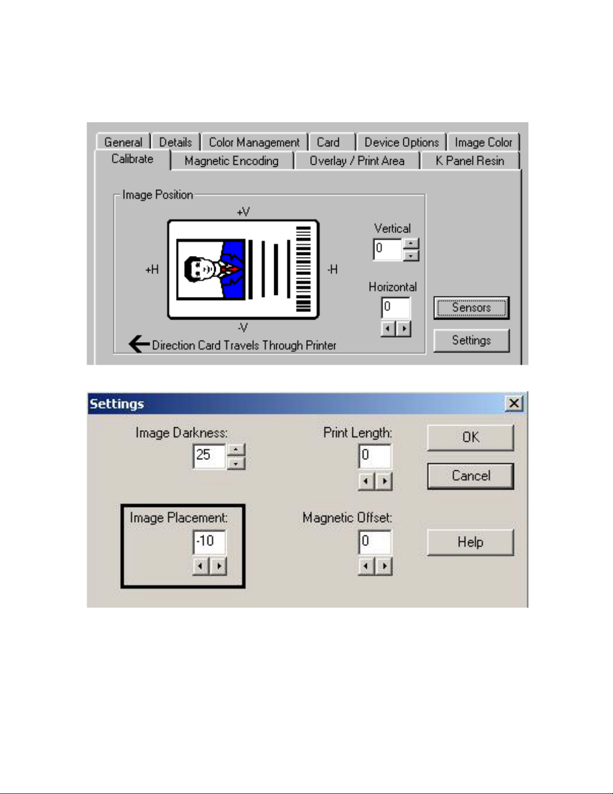
RESTRICTED USE ONLY Fargo Electronics, Inc.
Resolving the Ribbon Breaking issues (continued)
See the previous procedure in this section.
Persona C16 Card Printer Service Manual (Rev. 5.0)
Continued on the next page
44
Page 54

RESTRICTED USE ONLY Fargo Electronics, Inc.
Resolving the Ribbon Breaking issues (continued)
Step Procedure
4 Adjust the Image Placement positively.
a. Reset the Printer to clear any Error Messages by removing Power and
reapplying.
b. Open the Printer Control Panel from the Computer.
• If using Windows 95/98/ME, right click on the C11_C16 Card Printer Icon
and select Properties.
• If using Windows NT 4.0, right click on the C11_C16 Card Printer and
select Document Defaults.
• If using Windows 2000/XP, right click on the C11_C16 Card Printer and
select Printing Preferences.
c. Click the Calibrate tab.
d. Click on the Settings button.
e. Adjust the Image Placement setting by +10. (See the previous page.)
f. Click on OK.
g. Print a Self-Test.
h. After adjusting the Image Placement, if a white edge appears on the card,
adjust the image placement back toward its original value in increments of 2
until the white edge is gone.
Persona C16 Card Printer Service Manual (Rev. 5.0)
45
Page 55

RESTRICTED USE ONLY Fargo Electronics, Inc.
Encoding Errors
Resolving the Mag Verify Error Message
Symptoms: A Mag Verify error is displayed on the LED when attempting to encode.
Step Procedure
1 Check to ensure that the cards are loaded with the Magnetic Stripe facing down
and towards the back of the Printer.
2 Verify the Driver settings if cards are loaded properly. See the Using the Magnetic
Encoding tab procedure in Section 3, page 88. See the Magnetic Encoding tab
window on next page.
3 Verify that data is being encoded to the Magnetic Stripe.
a. Clear any Error Messages from the LCD by unplugging the Printer and
reapplying power.
b. Remove the failed card.
c. Use a Magnetic Stripe reader or magnetic developer spray to determine if data
is being written to the Magnetic Stripe.
d. If data is not being written to the Magnetic Stripe, remove the back cover and
verify that the magnetic head is plugged into J18 on the main board.
e. If the Magnetic head connection is properly seated, replace the magnetic head
(as needed). See the Replacing the Magentic Head Assembly (High-Coercivity:
83019012 or Low-Coercivity: 83019012) procedure in Section 5, page 174.
f. If data is being written to the Magnetic Stripe, the Magnetic Offset may need to
be adjusted. See the Resolving the Mag Verify Error Message
Section 3, page 46.
4 Verify that the coercivity of the cards matches the type of Mag Head installed in
the Printer.
Continued on the next page
procedure in
Persona C16 Card Printer Service Manual (Rev. 5.0)
46
Page 56

RESTRICTED USE ONLY Fargo Electronics, Inc.
Resolving the Mag Verify Error Message (continued)
See the previous procedure in this section.
Persona C16 Card Printer Service Manual (Rev. 5.0)
47
Page 57

RESTRICTED USE ONLY Fargo Electronics, Inc.
Resolving the Printer’s inability to read Encoded Data
Step Procedure
1 Verify that the cards are loaded properly with the Magnetic Stripe facing down
and towards the back of the Printer.
2 Verify that the card is encoded with magnetic data by using a Magnetic Imager
or Developer Solution.
3
Use WordPad (a Windows 95/ 98/ ME/ NT/ 2000/XP word processing program
in the Accessories Program Group).
a. Go to the File menu and select Page Setup.
b. Click on the Printer button and select the C16 Card Printer.
c. Click on OK and reset all four margins to zero. (Note: The WordPad will
automatically replace the values with its minimum margins.)
d. Open the program and type in: ~1%JULIEANDERSON^1234567890?
e. Go to File on the menu bar and select Print. (Note: The Printer should then
feed a card into the Encoder and magnetically encode the above string to it.)
4 Check the Magnetic Offset Setting.
a. Reset the Printer to clear any Error Messages by removing the power and
reapplying it.
b. Open the Printer Control Panel from the Computer.
• If using Windows 95/98/ME, right click on the C11_C16 Card Printer Icon
and select Properties.
• If using Windows NT 4.0, right click on the C11_C16 Card Printer and
select Document Defaults.
• If using Windows 2000/XP, right click on the C11_C16 Card Printer and
select Printing Preferences.
c. Click the Calibrate tab. Click on the Settings button.
d. Ensure that the Magnetic Offset setting matches the value that is written on
the bottom of the Printer.
e. If the values do not match, change the value in the Settings box.
5 Verify that the coercivity of the cards matches the type of Mag Head installed in
the Printer.
6 Verify that the Magnetic Stripe on the card is free of scratches or voids.
Persona C16 Card Printer Service Manual (Rev. 5.0)
48
Page 58

RESTRICTED USE ONLY Fargo Electronics, Inc.
Resolving Data intended for Magnetic Stripe (being printed on the
card) problem
Step Procedure
1 Confirm that the application is formatting the magnetic string correctly. See the
Using the Magnetic Track Options
procedure in Section 3, page 104.
2
Use WordPad (a Windows 95/ 98/ ME/ NT/ 2000/XP word processing program
in the Accessories Program Group).
a. Go to the File menu and select Page Setup.
b. Click on the Printer button and select the C16 Card Printer.
c. Click on OK and reset all four margins to zero. (Note: The WordPad will
automatically replace the values with its minimum margins.)
d. Open the program and type in: ~1%JULIEANDERSON^1234567890?
e. Go to File on the menu bar and select Print.
Note #1: The Printer should then feed a card into the Encoder and magnetically
encode the above string.)
Note #2: If Encoding from WordPad works properly, both the Printer and
communication from the computer are working properly. This indicates that the
issue is with the software application that is being used.
Persona C16 Card Printer Service Manual (Rev. 5.0)
49
Page 59

RESTRICTED USE ONLY Fargo Electronics, Inc.
Diagnosing Image Problems
Resolving the Pixel Failure problems
Symptom: A thin line or scratch travels the entire length of the card.
Step Procedure
1 Check the card stock for scratches. Replace the cards (as needed).
2 Examine the Printhead for visible damage.
3 Clean the Printhead. See Cleaning the Printhead procedure in Section 4, page
150.
4 Clean the Platen Rollers. See Cleaning the Platen Rollers procedure in Section
4, page 153.
5 Replace the printhead if the problem persists. See the Replacing the Printhead
Assembly (820199) procedure in Section 5, page 166.
Persona C16 Card Printer Service Manual (Rev. 5.0)
50
Page 60

RESTRICTED USE ONLY Fargo Electronics, Inc.
Resolving the Card Surface Debris problems
Symptom: Prints have spots (white or colored voids) and/or dust on them.
Step Procedure
1 Be sure the cards are clean and stored in a dust-free environment. Do not use
cards with embedded contaminants in the surface.
2 Clean the inside of the Printer. See Cleaning the Printer’s Interior procedure in
Section 4, page 154.
3 Clean the Platen Rollers. See Cleaning the Platen Rollers procedure in Section
4, page 153.
4 Clean the Cleaning Roller. See Cleaning the Card Feed and Cleaning Rollers in
Section 4, page 150.
Persona C16 Card Printer Service Manual (Rev. 5.0)
51
Page 61

RESTRICTED USE ONLY Fargo Electronics, Inc.
Resolving the Incorrect Image Darkness problems
Symptom: Printed cards are too dark or too light.
Step Procedure
1 Run a self-test to ensure that the issue is not with the driver settings.
2
Adjust the Dye-Sub Intensity setting within the Image Color tab of the Printer
Driver. See Using the Image Color tab
procedure in Section 3, page 95.
Continued on the next page
Persona C16 Card Printer Service Manual (Rev. 5.0)
52
Page 62

RESTRICTED USE ONLY Fargo Electronics, Inc.
Resolving the Incorrect Image Darkness problems (continued)
Step Procedure
3
Correct the Image Darkness. See Using the Image Darkness option in Section
3, page 79.
Persona C16 Card Printer Service Manual (Rev. 5.0)
53
Page 63

RESTRICTED USE ONLY Fargo Electronics, Inc.
Resolving the Ribbon Wrinkle problems
Symptom: Printed cards have off-colored lines or streaks on them.
Step Procedure
1 Confirm that the Printer is using the most current driver via: http://www.fargo.com
2
Reduce the Dye-Sub Intensity setting within the Image Color tab of the Printer
Driver. See the Using the Image Color tab
procedure in Section 3, page 95.
Continued on the next page
Persona C16 Card Printer Service Manual (Rev. 5.0)
54
Page 64

RESTRICTED USE ONLY Fargo Electronics, Inc.
Resolving the Ribbon Wrinkle problems (continued)
Step Procedure
3 Reduce the Image Darkness. See Using the Image Darkness option in Section
3, page 79.
Persona C16 Card Printer Service Manual (Rev. 5.0)
55
Page 65

RESTRICTED USE ONLY Fargo Electronics, Inc.
Resolving the Excessive Resin Printing problems
Symptom: Black resin text and barcodes appear smeared or too thick.
Step Procedure
1 Reduce the Resin Heat setting within the Image Color tab of the Printer Driver.
See the Using the Image Color tab
procedure in Section 3, page 95.
Continued on the next page
Persona C16 Card Printer Service Manual (Rev. 5.0)
56
Page 66

RESTRICTED USE ONLY Fargo Electronics, Inc.
Resolving the Excessive Resin Printing problems (continued)
Step Procedure
2 Reduce the Image Darkness. See Using the Image Darkness option in Section 3,
page 79.
Persona C16 Card Printer Service Manual (Rev. 5.0)
57
Page 67

RESTRICTED USE ONLY Fargo Electronics, Inc.
Resolving the Incomplete Resin Printing problems
Symptom: Black resin text and barcodes appear faded or too light.
Step Procedure
1
2
Increase the Resin Heat setting within the Image Color tab of the Printer
Driver. See the Using the Image Color tab
procedure in Section 3, page 95.
Increase the Image Darkness. See Using the Image Darkness option in
Section 3, page 79.
Persona C16 Card Printer Service Manual (Rev. 5.0)
58
Page 68

RESTRICTED USE ONLY Fargo Electronics, Inc.
Resolving the Image Placement problems
Symptom: Printing is cut off or is not centered on the card or a white border appears.
Step Procedure
1 Verify if the Image Position option within the Calibrate tab is set incorrectly.
a. Open the Printer Control Panel from the Computer.
• If using Windows 95/98/ME, right click on the C11_C16 Card Printer Icon
and select Properties.
• If using Windows NT 4.0, right click on the C11_C16 Card Printer and
select Document Defaults.
• If using Windows 2000/XP, right click on the C11_C16 Card Printer and
select Printing Preferences.
b. Click on the Calibrate tab.
c. Adjust the Vertical and/or Horizontal Image Position settings based on
where the white border is on the card.
Continued on the next page
Persona C16 Card Printer Service Manual (Rev. 5.0)
59
Page 69

RESTRICTED USE ONLY Fargo Electronics, Inc.
Resolving the Image Placement problems (continued)
Step Procedure
2
Verify if the Image Placement setting is set correctly or incorrectly. See Graphic
A on the next page.
a. Open the Printer Control Panel from the Computer.
• If using Windows 95/98/ME, right click on the C11_C16 Card Printer Icon
and select Properties.
• If using Windows NT 4.0 right click on the C11_C16 Card Printer and
select Document Defaults.
• If using Windows 2000/XP, right click on the C11_C16 Card Printer and
select Printing Preferences.
b. Click on the Calibrate tab.
c. Click on the Settings button.
• If the white border is on the leading edge of the card, adjust the Image
Placement value by –2.
• If the white border is on the trailing edge of the card, adjust the Image
Placement value by +2.
d. Click on OK.
e. Run a Self-Test.
f. If the white border is diminished, continue the adjustment until it is gone.
3 Adjust the Card Guide Bar (as needed). See Graphic B on the next page.
a. Open the Top Print Cover.
b. Loosen the two screws that hold the Card Guide Bar in place.
c. Carefully move the Card Guide Bar
(Note: Ensure that all adjustments leave the Card Guide Bar equidistant from the
rear side plate of the Printer.)
Persona C16 Card Printer Service Manual (Rev. 5.0)
60
Page 70

RESTRICTED USE ONLY Fargo Electronics, Inc.
Resolving the Image Placement problems (continued)
This is Graphic A.
This is Graphic B.
Persona C16 Card Printer Service Manual (Rev. 5.0)
61
Page 71

RESTRICTED USE ONLY Fargo Electronics, Inc.
Resolving the Poor Image Quality problems
Symptom: Photos on the cards look pixilated or grainy, as shown below.
Step Procedure
1 Use high-resolution, 24-bit color images to always capture an image:
• at a 24-bit color setting
• at 300 dpi
• at the same size that it will be printed on the card (as captured either with a
scanner or with a digital camera)
(Note: If a small or low-resolution image is stretched or blown up, a pixilated or
grainy effect will occur when printing, as shown below in the right photo.)
Persona C16 Card Printer Service Manual (Rev. 5.0)
62
Page 72

RESTRICTED USE ONLY Fargo Electronics, Inc.
Running the Self Test
Perform a self-test after (a) an initial setup of the Printer, (b) a calibration procedure has
been conducted or (c) a part has been replaced to check for proper Printer operation.
Step Procedure
1 Verify that a full-color ribbon is installed and that cards are properly loaded.
Caution: If the power is ON, disconnect the Power Cable from the
Printer’s rear panel.
2
3
4 The Printer will print a 3-color process gray scale on the front, flip the card and
Press and hold the Pause/Resume button.
While holding down the Pause/Resume button, plug the power cable back into the
Printer.
print the monochrome black panel on the back. The overlay pass is not printed
during the Self-test.
Running the Standard Self Test Print
This card will be printed.
PRO-LX
Persona C16 Card Printer Service Manual (Rev. 5.0)
63
Page 73

RESTRICTED USE ONLY Fargo Electronics, Inc.
Using the DIP Switch (Self-test)
Step Procedure
1 Activate any of these diagnostic tests and Calibration modes. See Running the
Self Test in Section 2, page 63. During the activation of the Self-test, the Printer
will:
• Detect the change to the DIP Switch Settings. See Using the DIP Switch Self
Test in Section 2, page 64.
• Operate the Printer in that selected Test or Calibration mode.
2 Return all the DIP switches back to their normal OFF position once the tests are
completed.
3 Leave the associated DIP switches activated to operate the Printer this way or
temporarily use the settings to test a particular Printer operation. (Note: When
altering a particular mode-of-operation (e.g., disabling the laminator or magnetic
verification), it will affect Printer operation while printing from a computer.)
4 When completed, turn OFF the power to the Printer to reset the operating mode
of the Printer.
• The first illustration (below) shows all eight (8) switches in the normal
OFF
position.
• The second illustration (below) shows Switches No. 1,2 and 3 in the ON
position. (Note: The Ribbon Sensor calibration without the need of a PC).
(Note: Refer to the DIP Switch Settings table on the next page for additional
diagnostic selections.)
Persona C16 Card Printer Service Manual (Rev. 5.0)
64
Page 74

RESTRICTED USE ONLY Fargo Electronics, Inc.
Setting the DIP Switch Settings
The capital letter “X” indicates that the switch should be set to ON or DOWN.
SW1 SW2 SW3 SW4 Diagnostic modes
X X X X Test5x3 is a standard YMCKO test card.
X X Mag123A is a mag-only test card (records on
the Magnetic Stripe).
X The RibTest calibrates the Ribbon Color
Sensor (none or anything except Mono
Resin).
X X X The ResinTest is a premium resin test card.
X X The TestCore allows reading of the core pins.
In this mode, the Printer will beep every time
a core pin is detected in the Ribbon Roll.
Persona C16 Card Printer Service Manual (Rev. 5.0)
65
Page 75

RESTRICTED USE ONLY Fargo Electronics, Inc.
Running the 15-Shade Self Test
This is the Self-test that appears when specific changes are made to the DIP Switch
Settings.
Persona C16 Card Printer Service Manual (Rev. 5.0)
66
Page 76
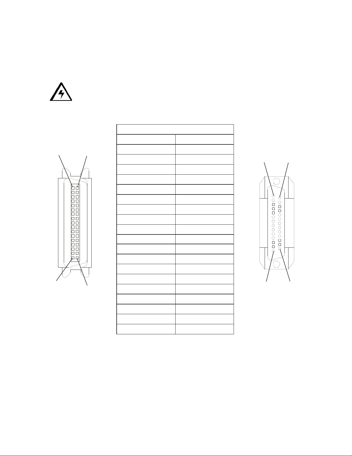
RESTRICTED USE ONLY Fargo Electronics, Inc.
WIRE DIAGRAM
19 Through 30
19 Through 25
14
13
25
Interfacing Information
The Printer is equipped with a standard 8-bit Centronics-type Parallel Data Communications
Port. (Note: The Printer's Parallel Interface Connector is a standard 36-pin Amp type with
two metal-wire retaining clips. It mates with a standard PC to Printer parallel cable.)
Caution: For best results, keep the Interface Cable to less than six (6) feet.
Reviewing the Pin Assignments
19
36
PIN 1
18
DB36P
DB25P
11
22
33
44
55
66
77
88
99
10 10
11 11
12 12
13 13
14 14
32 15
31 16
PIN 1
Persona C16 Card Printer Service Manual (Rev. 5.0)
36
17
Shell Shell
67
Page 77

RESTRICTED USE ONLY Fargo Electronics, Inc.
Reviewing the Centronics Parallel Pin Assignments
Signal
Funtion
Bit Name DB-25 M 1284A Pin # Centronics M 1284B Pin #
nStrobe C0 1 1
Data Bit 0 D0 2 2
Data Bit 1 D1 3 3
Data Bit 2 D2 4 4
Data Bit 3 D3 5 5
Data Bit 4 D4 6 6
Data Bit 5 D5 7 7
Data Bit 6 D6 8 8
Data Bit 7 D7 9 9
nAck S6 10 10
Busy S7 11 11
PaperEnd S5 12 12
Select S4 13 13
nAutoLF C1 14 14
Continued on the next page
Persona C16 Card Printer Service Manual (Rev. 5.0)
68
Page 78

RESTRICTED USE ONLY Fargo Electronics, Inc.
Reviewing the Centronics Parallel Pin Assignments (continued)
Signal Funtion Bit Name DB-25 M 1284A Pin # Centronics M 1284B Pin #
nError (nFault) S3 15 32
nInit C2 16 31
nSelectIn C3 17 36
Grnd Rtn 18 19
Grnd Rtn 19 20
Grnd Rtn 19 21
Grnd Rtn 20 22
Grnd Rtn 20 23
Grnd Rtn 21 24
Grnd Rtn 21 25
Grnd Rtn 22 26
Grnd Rtn 22 27
Grnd Rtn 23 29
Grnd Rtn 24 28
Grnd Rtn 25 30
Continued on the next page
Persona C16 Card Printer Service Manual (Rev. 5.0)
69
Page 79

RESTRICTED USE ONLY Fargo Electronics, Inc.
Reviewing the Centronics Parallel Pin Assignments (continued)
Signal Funtion Bit Name DB-25 M 1284A Pin # Centronics M 1284B Pin #
Ch. Grnd 17
Perif. Hi. 18
Unused 15
Unused 33
Unused 34
Unused 35
Persona C16 Card Printer Service Manual (Rev. 5.0)
70
Page 80
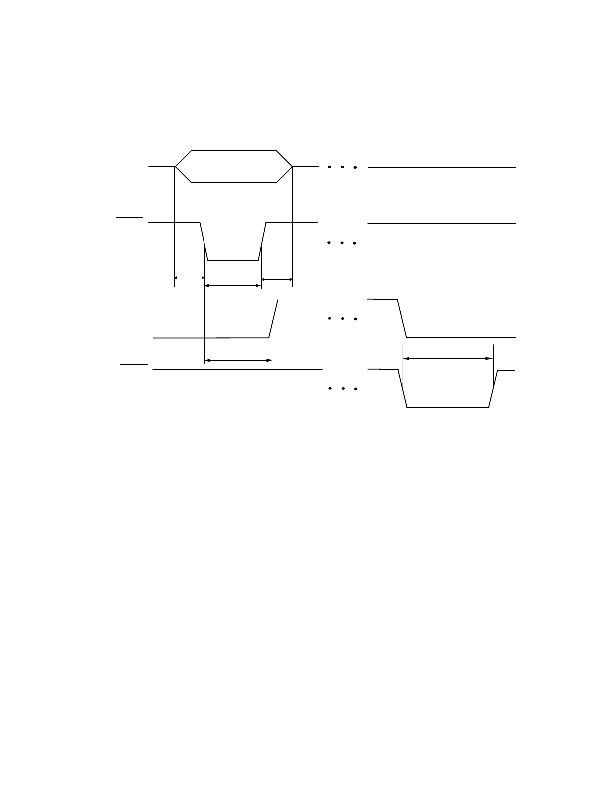
RESTRICTED USE ONLY Fargo Electronics, Inc.
Reviewing the Printer Timing Diagram
The timing diagram (below) illustrates the data and handshake lines during the transfer of
one data byte to the Computer.
Data 0 - Data 7
Strobe
Busy
Acknlg
Tdsu
DATA VALID
Tstr
Tbp
Tdh
Tack
Persona C16 Card Printer Service Manual (Rev. 5.0)
71
Page 81
RESTRICTED USE ONLY Fargo Electronics, Inc.
Reviewing the Printer Timing
Interval Description Minimum Value
Tdsu Data setup time 0.5 \s
Tstr Data strobe width
1 \s
Tack
Acknlg pulse width
3.75 \s
Tdh Data hold time 0.5 \s
Tsb
Busy delay time from data
strobe
0.5 \s (max.)
Persona C16 Card Printer Service Manual (Rev. 5.0)
72
Page 82

RESTRICTED USE ONLY Fargo Electronics, Inc.
Section 3: Printer Adjustments
Safety Messages (review carefully)
Symbol Critical Instructions for Safety purposes
Danger: Failure to follow these installation guidelines can result in death or
serious injury.
Information that raises potential safety issues is indicated by a warning
symbol (as shown to the below).
• To prevent personal injury, refer to the following safety messages
before performing an operation preceded by this symbol.
• To prevent personal injury, always remove the power cord prior to
performing repair procedures, unless otherwise specified.
• To prevent personal injury, make sure only qualified personnel
perform these procedures.
Caution: This device is electrostatically sensitive. It may be damaged if
exposed to static electricity discharges.
Information that raises potential electrostatic safety issues is indicated
by a warning symbol (as shown to the below).
• To prevent equipment or media damage, refer to the following
safety messages before performing an operation preceded by this
symbol.
• To prevent equipment or media damage, observe all established
Electrostatic Discharge (ESD) procedures while handling cables in
or near the Circuit Board and Printhead Assemblies.
• To prevent equipment or media damage, always wear an
appropriate personal grounding device (e.g., a high quality wrist
strap grounded to avoid potential damage).
• To prevent equipment or media damage, always remove the
Ribbon and Cards from the Printer before making any repairs,
unless otherwise specified.
• To prevent equipment or media damage, take jewelry off of
fingers and hands, as well as thoroughly clean hands to remove oil
and debris before working on the Printer.
Persona C16 Card Printer Service Manual (Rev. 5.0)
73
Page 83

RESTRICTED USE ONLY Fargo Electronics, Inc.
Adjusting for CR-79 Adhesive Back Cards
The Printer is designed to print on both standard CR-80 ("credit card") sized cards and CR79 sized card sizes.
• The CR-79 cards are slightly smaller than CR-80 sized cards with a thickness of 20 mil
(.020"/.5mm).
• The CR-79 card size relates to the adhesive back cards (used in applications where they
are printed and applied to thicker proximity cards).
Step Procedure
1 If the Printer does not have a Magnetic Stripe encoder:
a. Do not adjust for the different card sizes.
b. Disregard this procedure. (Note: The Printer's factory setting will
accommodate both.)
2 If the Printer does include a Magnetic Stripe encoder and you are printing with
CR-79 sized cards:
a. Adjust for the different card sizes.
b. Refer to the next two pages to make card size adjustments to the Printer's
Internal Card Guide.
• The Internal Card Guide holds the card in position as it feeds through the
Printer.
• This guide is factory-set to optimize both printing and magnetic Encoding
on CR-80 sized cards. See the next page.)
Persona C16 Card Printer Service Manual (Rev. 5.0)
74
Page 84

RESTRICTED USE ONLY Fargo Electronics, Inc.
Adjusting for CR-79 Adhesive Back Cards (continued)
This is the CR-80 Position (Standard Setting from Factory). See the previous procedure in
this section.
Persona C16 Card Printer Service Manual (Rev. 5.0)
75
Page 85

RESTRICTED USE ONLY Fargo Electronics, Inc.
Adjusting for CR-79 Adhesive Back Cards (continued)
Step Procedure
1
If you are loading CR-79 cards, this guide must be adjusted to accommodate this
smaller, thinner card stock.
a. Open the Printer's Top Cover.
b. Move the Adjustment Lever back, over and down into the CR-79 position to
narrow the card path (so it holds these smaller cards more securely). (Note:
The Internal Card Guide only moves a slight distance. This position is critical
for maintaining sharp image registration.)
c. Be sure to always set this adjustment lever according to the card size already
loaded in the Printer.
The CR-79 Position (used to adjust only if printing CR-79 sized cards) is displayed below.
Persona C16 Card Printer Service Manual (Rev. 5.0)
76
Page 86

RESTRICTED USE ONLY Fargo Electronics, Inc.
Adjusting the Magnetic Encoding Head
Use this procedure to adjust the coercivity of the Magnetic Encoding Head.
Tools Needed: Phillips Head Screwdriver, Small Standard Screwdriver, Digital Voltmeter
Steps Procedure
1
Caution: Turn off the Printer and unplug the power cord from the
Printer.
2 Open the Upper Imaging Assembly.
3 Loosen the top two corner screws (130987) found just behind the top edge of the
Rear Cover.
4 Close the Upper Imaging Assembly.
5 Remove the screw (130987) by the Card Exit Ramp.
6 Remove the Rear Cover.
7 Locate the Potentiometer labeled RP4.
8 Locate the test point labeled TP8
9 Place the positive lead of the voltmeter on TP8. Place the negative lead on
ground.
10 Adjust RP4 until the voltage on TP8 reads 6.0 volts DC on the voltmeter for High
Coercivity or 2.5 volts DC on the voltmeter for Low Coercivity.
Persona C16 Card Printer Service Manual (Rev. 5.0)
77
Page 87

RESTRICTED USE ONLY Fargo Electronics, Inc.
C16 Print Driver Options
Using the Settings dialog box
Access the Settings dialog box via the Settings button on the Calibrate tab. Use the
adjustment mode to change the Printer's internal settings for overall Image Darkness, Image
Placement, Print Length and Magnetic Offset. (Note: The Card Printer is equipped with an
internal adjustment mode programmable through the Settings dialog box. This dialog box is
accessible only if the Printer is powered ON, in Ready Mode and is properly connected to the
PC.)
Step Procedure
1 Change these settings according to the original settings recorded on a label
attached to the Printer's base plate or rear panel or refer to the remainder of this
Section. (Note: These can be helpful to get back to the Printer's original
baseline settings.)
Caution! These settings are optimized at the factory and in most
cases, they will not need to be changed.
Persona C16 Card Printer Service Manual (Rev. 5.0)
78
Page 88

RESTRICTED USE ONLY Fargo Electronics, Inc.
Using the Image Darkness option
Use this option to set the overall darkness of the printed image by increasing or decreasing
the amount of heat used by the Printhead when printing.
Step Procedure
1 Lighten the printed image by clicking the down arrow to enter a negative
value and decrease the amount of Printhead heat.
OR
Darken the image by clicking the up arrow
increase the amount of Printhead heat.
Maximum Adjustment Range: The maximum adjustment range is ±100.
Caution #1: For best results, make slight adjustments of only ± 4 to
avoid accidentally over-adjusting the Printhead heat.
Caution #2: If the positive value is set too high, the print ribbon may
jam or even break.
to enter a positive value and
Using the Image Placement option
Use this option to adjust the lengthwise or horizontal position of the printed image on a card
so it appears centered. (Note: When adjusting this value, keep in mind that cards always
remain in the same landscape orientation while moving through the Printer.)
Persona C16 Card Printer Service Manual (Rev. 5.0)
79
Page 89

RESTRICTED USE ONLY Fargo Electronics, Inc.
Rear of Printer
Front of Printer
he diagram (below) represents how the printed image will move in relation to the fixed card
T
position as a positive or negative Image Placement value is entered.
Step Procedure
1 Click on the left arrow to enter a positive value to move the printed image
toward the leading edge of the card or the card output to the side of the Printer.
OR
Click on the right arrow
toward the trailing edge of the card or the card input to the side of the Printer.
• Printed Image Direction: The arrows on these buttons indicate the direction
the printed image will move on the card.
• Maximum Adjustment Range: The maximum adjustment range is ±100. As a
rule, 10 equals about .030"/. 8mm, which is about the same as the thickness of
a standard CR-80 size card.
Card Output
Side of Printer
(Leading Edge
of Card)
to enter a negative value to move the printed image
Caution: If positive value is set too high, the print ribbon may break.
Card Input
Side of Printer
(Trailing Edge
of Card)
Direction card travels through printer
Persona C16 Card Printer Service Manual (Rev. 5.0)
80
Page 90

RESTRICTED USE ONLY Fargo Electronics, Inc.
Rear of Printer
Front of Printer
-
Using the Print Length option
Use this option to reduce or increase the overall printable area in order to optimize edge-toedge printing toward the trailing edge of a card. (Note: When adjusting this value, keep in
mind that cards always remain in the same position while moving through the Printer.)
The diagram (below) represents how the end of form will move in relation to the fixed card
position as a positive or negative Print Length value is entered.
Step Procedure
1 Click on the left arrow to enter a positive value to reduce the print length and
move the end of the printable area more toward the leading edge of the card.
OR
Click on the right arrow to enter a negative value to increase the print length and
move the end of the printable area more toward the trailing edge of the card.
• Printed Image Direction: Notice the arrows on these buttons indicate the
direction the length of the printable area will move on the card.
• Maximum Adjustment Range: The maximum adjustment range is ±100. As a
rule, 10 equals about .030"/. 8mm, which is about the same as the thickness of
a standard CR-80 size card.)
Card Output
Side of Printer
(Leading Edge
of Card)
Direction card travels through printer
Persona C16 Card Printer Service Manual (Rev. 5.0)
Card Input
Side of Printer
(Trailing Edge
of Card)
81
Page 91

RESTRICTED USE ONLY Fargo Electronics, Inc.
Using the Magnetic Offset option
Use this option only if the Printer has a built-in Magnetic Stripe encoder.
• Use it to shift the starting point of where the Printer will begin Encoding the magnetic
track data on a card's Magnetic Stripe.
• When adjusting this value, keep in mind that a card and its Magnetic Stripe will always
remain in the same relative position as the card travels through the Printer.
The diagram (on the next page) represents how the magnetic data will move in relation to the
fixed position of a card's Magnetic Stripe as a positive or negative Magnetic Offset value is
entered. (Note: For this diagram, imagine that the card is transparent and the card's mag
stripe can be seen through the top or front side of the card.)
Persona C16 Card Printer Service Manual (Rev. 5.0)
82
Page 92
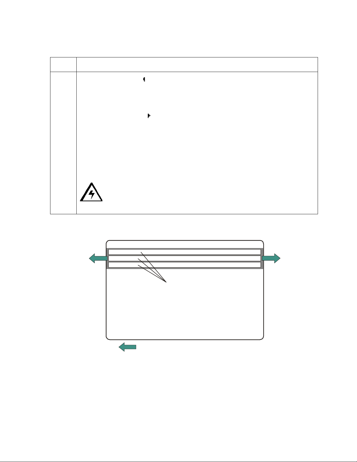
RESTRICTED USE ONLY Fargo Electronics, Inc.
Rear of Printer
Front of Printer
-
Using the Magnetic Offset option (continued)
Step Procedure
1 Click on the left arrow to enter a positive value to move the start of the magnetic
data more toward the leading edge of the card or the card output to the side of the
Printer.
OR
Click on the right arrow
magnetic data toward the trailing edge of the card or the card input to the side of
the Printer.
• Magnetic Data Direction: The arrows on these buttons indicate the direction
the magnetic data will move on the card's Magnetic Stripe.
• Maximum Adjustment Range: The maximum adjustment range is ±100. As a
rule, 10 equals about .030"/. 8mm.) (Note: Keep this in mind when adjusting
this option to avoid over-adjusting.)
Caution: If the negative value is set too high, the Printer may start
Encoding before the card's Magnetic Stripe reaches the Encoding head.
to enter a negative value to move the start of the
+
Card Output
Magnetic Track Data
Side of Printer
(Leading Edge
of Card)
Direction card travels through printer
Persona C16 Card Printer Service Manual (Rev. 5.0)
Card Input
Side of Printer
(Trailing Edge
of Card)
83
Page 93

RESTRICTED USE ONLY Fargo Electronics, Inc.
Using the Card tab
Adjusting the Card Size Option
Step Description
1
Click on the inches or mm option to choose the desired unit of measurement.
(Note #1: When designing a card format, always set the card size or page
size within the card design program to the exact dimensions of a CR-80 card.)
(Note #2: The Card Size indicates that the Printer accepts standard, "credit
card" size CR-80 (ISO ID-1) cards. The dimensions of the total print area for
this card size appear in the Print Width and Print Length boxes.)
Persona C16 Card Printer Service Manual (Rev. 5.0)
84
Page 94

RESTRICTED USE ONLY Fargo Electronics, Inc.
Adjusting the Orientation Option
Step Description
1
Select Portrait under Orientation to cause the card to print in a vertical
orientation.
OR
Select Landscape under Orientation to cause the card to print in a horizontal
orientation.
(Note: An icon illustrating a printed card helps represent the difference
between the two.)
Persona C16 Card Printer Service Manual (Rev. 5.0)
85
Page 95

RESTRICTED USE ONLY Fargo Electronics, Inc.
Using the Copies Option
Step Description
1
Specify the number of copies to be printed under Copies.
Using the Test Print Button
Step Description
1
Click on the Test Print button to send a simple self-test print to the Printer.
• Ensure that a full-color print ribbon is installed.
• Ensure that the computer is effectively communicating with the Printer and
that the Printer is functioning properly.
Persona C16 Card Printer Service Manual (Rev. 5.0)
86
Page 96

RESTRICTED USE ONLY Fargo Electronics, Inc.
Using the About Button
Step Description
1
Click on the About button to open a dialog box containing the copyright and
version information about this Printer Driver software.
Persona C16 Card Printer Service Manual (Rev. 5.0)
87
Page 97

RESTRICTED USE ONLY Fargo Electronics, Inc.
Using the Device Options tab
Adjusting the Ribbon Type option
Use the Ribbon Type option to select print ribbons.
Step Description
1
Select the appropriate print Ribbon Type option from the dropdown menu for
the type of print ribbon in use.
• YMCKO – Full Color/Resin Black/Overlay
• BO – Dye-Sub Black/Overlay
• K – Standard Resin
• K – Premium Resin
• Colored Resin
• Metallic Resin
• Scratch-Off Resin
Persona C16 Card Printer Service Manual (Rev. 5.0)
88
Page 98

RESTRICTED USE ONLY Fargo Electronics, Inc.
Adjusting the Color matching option
Use the Color matching dropdown menu to choose the color matching options which best
fits the print job requirements.
Step Description
1
Select None for print speed versus print color or for use of third party color
matching software.
OR
Select Algebraic (a) for the Printer Driver to make very simple, yet fast, color
balance adjustments; (b) for more natural looking images without actually
utilizing any specific color matching; or (c) for customized, printed coloring of
the cards through the Image Color tab.
OR
Select Monitor for the Printer Driver to make color corrections similar to the
Algebraic option but through a more complex color matching algorithm. (Note:
This option shifts colors to a different color model so the colors in the image
will more closely match how they appear on the monitor.)
Persona C16 Card Printer Service Manual (Rev. 5.0)
89
Page 99

RESTRICTED USE ONLY Fargo Electronics, Inc.
Adjusting for the Resin Dither
Select the appropriate dither method according to the type of image to be printed.
Step Procedure
1
Select Optimized for Photo when printing photo quality images with resin.
OR
Select Optimized for Graphics when printing drawings and graphics (e.g.,
clipart, logos, etc.) with resin.
Persona C16 Card Printer Service Manual (Rev. 5.0)
90
Page 100

RESTRICTED USE ONLY Fargo Electronics, Inc.
Using the Rotate Image 180 Degrees option
Use this option to rotate the image on the front of the card 180 degrees when printed.
Step Description
1 Select this option to change the position of the printed image in relation to the
set location of a card's Magnetic Stripe or smart chip.
Persona C16 Card Printer Service Manual (Rev. 5.0)
91
 Loading...