

Farallon Communications R9100 User Manual

Netopia™ R9100 Ethernet Router
for DSL and Cable Modems
User’s Reference Guide

Copyright
©1997–98, Netopia, Inc., v.0300
All rights reserved. Printed in the U.S.A.
This manual and any associated artwork, software, and product designs are copyrighted with
all rights reserved. Under the copyright laws such materials may not be copied, in whole or
part, without the prior written consent of Netopia, Inc. Under the law, copying includes
translation to another language or format.
Netopia, Inc.
2470 Mariner Square Loop
Alameda, CA 94501-1010
U.S.A.
Patents
PhoneNET technology contained in Netopia is covered by U.S. Patent Numbers 4,901,342
and 5,003,579.
Other U.S. and foreign patents are pending.
Part Number
For additional copies of this electronic manual, order Netopia part number 6120339-PF-03
Printed Copies
For printed copies of this manual, order Netopia part number TER9100/Doc
(P/N 6120339-00-02)

CCCCoooonnnntttteeeennnnttttss
ss
Welcome to the Netopia R9100 Ethernet Router
be your single source for information about your Netopia R9100 Ethernet Router. It is intended to
be viewed on-line, using the powerful features of the Adobe Acrobat Reader. The information
display has been deliberately designed to present the maximum information in the minimum space
on your screen. You can keep this document open while you perform any of the procedures
described, and find useful information about the procedure you are performing.
This Table of Contents page you are viewing consists of hypertext links to the chapters and
headings listed. If you are viewing this on-line, just click any link below to go to that heading.
User’s Reference Guide
. This guide is designed to
Part I: Getting Started
Chapter 1 — Introduction..........................................................1-1
Overview....................................................................... 1-1
Features and capabilities ............................................... 1-1
How to use this guide .................................................... 1-2
Chapter 2 — Setting Up Internet Services .................................2-1
Finding an Internet service provider................................. 2-1
Unique requirements............................................ 2-1
Pricing and support.............................................. 2-1
Endorsements ..................................................... 2-2
Deciding on an ISP account............................................ 2-2
Setting up an account using a Netopia R9100........ 2-2
Obtaining an IP address........................................ 2-2
SmartIP............................................................... 2-2
Obtaining information from the ISP.................................. 2-2
Local LAN IP address information to obtain............ 2-3
G
B
Chapter 3 — Making the Physical Connections..........................3-1
Find a location............................................................... 3-1
What you need .............................................................. 3-2
Identify the connectors and attach the cables.................. 3-2
Netopia R9100 Ethernet Router back panel ports............ 3-3
Netopia R9100 Ethernet Router status lights................... 3-4
Chapter 4 — Connecting to Your Local Area Network.................4-1
Overview....................................................................... 4-1
Network Model..................................................... 4-2
Readying computers on your local network....................... 4-4

ii User’s Reference Guide
Connecting to an Ethernet network.................................. 4-5
10Base-T............................................................. 4-5
Adding an external modem ............................................. 4-7
Connecting to a LocalTalk network ................................. 4-8
Wiring guidelines for PhoneNET cabling.................. 4-9
Chapter 5 — Setting up your Router with the SmartStart Wizard 5-1
Before running SmartStart ............................................. 5-2
Setting up your Router with the SmartStart Wizard........... 5-3
SmartStart Wizard configuration screens ............... 5-3
Easy option.......................................................... 5-4
Advanced option .................................................. 5-5
Sharing the Connection.................................................. 5-6
Configuring TCP/IP on Windows 95, 98, or NT
computers........................................................... 5-6
Configuring TCP/IP on Macintosh computers........ 5-10
Chapter 6 — Console-Based Management.................................6-1
Connecting through a Telnet session............................... 6-2
Configuring Telnet software ................................... 6-3
Connecting a console cable to your router ....................... 6-3
Navigating through the console screens .......................... 6-4
Chapter 7 — Easy Setup...........................................................7-1
Easy Setup console screens........................................... 7-1
Accessing the Easy Setup console screens............ 7-1
Quick Easy Setup connection path .................................. 7-3
If your ISP supports DHCP .................................... 7-3
If your ISP doesn’t support DHCP.......................... 7-3
More Easy Setup options ............................................... 7-5
WAN Ethernet Configuration .................................. 7-5
IP Easy Setup ...................................................... 7-6
Easy Setup Security Configuration ......................... 7-7

Contents iii
Part II: Advanced Configuration
Chapter 8 — WAN and System Configuration .............................8-1
WAN configuration.......................................................... 8-1
Creating a new Connection Profile................................... 8-3
Default Answer Profile for Dial-in Connections .................. 8-7
How the Default Answer Profile works.................... 8-7
System configuration screens ........................................ 8-9
Navigating through the system configuration screens...... 8-10
System configuration features............................. 8-11
Network protocols setup..................................... 8-11
Filter sets (firewalls)........................................... 8-12
IP address serving ............................................. 8-12
Date and time.................................................... 8-12
Console configuration......................................... 8-12
SNMP (Simple Network Management Protocol)..... 8-13
Security............................................................. 8-13
Upgrade feature set ........................................... 8-13
Logging ............................................................. 8-14
Installing the Syslog client .................................. 8-14
G
Chapter 9 — IP Setup and Network Address Translation ............9-1
Network Address Translation features ............................. 9-1
Using Network Address Translation................................. 9-3
Associating port numbers with nodes.................... 9-5
Network Address Translation guideline................... 9-5
IP setup........................................................................ 9-6
IP subnets......................................................... 9-10
Static routes...................................................... 9-12
IP address serving....................................................... 9-16
IP Address Pools................................................ 9-19
DHCP NetBIOS Options....................................... 9-21
MacIP (KIP forwarding) setup .............................. 9-23

iv User’s Reference Guide
Chapter 10 — IPX Setup.........................................................10-1
IPX features ................................................................ 10-1
IPX definitions ............................................................. 10-1
Internetwork Packet Exchange (IPX) ..................... 10-1
IPX address....................................................... 10-2
Socket .............................................................. 10-2
Routing Information Protocol (RIP) ....................... 10-2
Service Advertising Protocol (SAP)....................... 10-2
NetBIOS............................................................ 10-3
IPX spoofing....................................................... 10-3
IPX setup screen ......................................................... 10-3
IPX routing tables ........................................................ 10-5
Chapter 11 — AppleTalk Setup................................................11-1
AppleTalk networks ...................................................... 11-1
AppleTalk protocol.............................................. 11-1
MacIP................................................................ 11-3
AURP................................................................. 11-3
Routers and seeding .......................................... 11-3
Installing AppleTalk ...................................................... 11-4
Configuring AppleTalk ................................................... 11-6
EtherTalk setup.................................................. 11-6
LocalTalk setup ................................................. 11-7
AURP setup ....................................................... 11-8
Chapter 12 — Monitoring Tools...............................................12-1
Quick View status overview .......................................... 12-1
General status................................................... 12-2
Status lights...................................................... 12-2
Statistics & Logs......................................................... 12-3
General Statistics .............................................. 12-4
Event histories ............................................................ 12-5
Routing tables............................................................. 12-7
Served IP Addresses.................................................. 12-10

Contents v
System Information.................................................... 12-12
SNMP....................................................................... 12-12
The SNMP Setup screen................................... 12-13
SNMP traps..................................................... 12-14
SmartView ................................................................ 12-16
SmartView overview ........................................ 12-16
Navigating SmartView....................................... 12-16
General Machine information page .................... 12-17
Event history pages.......................................... 12-17
Standard HTML web-based monitoring pages ..... 12-19
Chapter 13 — Security ...........................................................13-1
Suggested security measures....................................... 13-1
User accounts............................................................. 13-1
Dial-in console access.................................................. 13-3
Enable SmartStart/SmartView/Web server ................... 13-4
Telnet access .............................................................. 13-4
About filters and filter sets ........................................... 13-4
What’s a filter and what’s a filter set?.................. 13-4
How filter sets work............................................ 13-5
How individual filters work................................... 13-7
Design guidelines............................................. 13-11
Working with IP filters and filter sets............................ 13-12
Adding a filter set............................................. 13-13
Viewing filter sets............................................. 13-16
Modifying filter sets.......................................... 13-17
Deleting a filter set........................................... 13-17
A sample IP filter set........................................ 13-17
IPX filters .................................................................. 13-21
IPX packet filters.............................................. 13-22
IPX packet filter sets ........................................ 13-23
IPX SAP filters.................................................. 13-25
IPX SAP filter sets ............................................ 13-27
G

vi User’s Reference Guide
Firewall tutorial.......................................................... 13-29
General firewall terms ...................................... 13-29
Basic IP packet components............................. 13-29
Basic protocol types......................................... 13-29
Firewall design rules......................................... 13-30
Filter basics..................................................... 13-32
Example filters................................................. 13-33
Chapter 14 — Utilities and Diagnostics...................................14-1
Ping............................................................................ 14-2
Trace Route................................................................. 14-4
Telnet client................................................................. 14-5
Disconnect Telnet console session ............................... 14-6
Factory defaults........................................................... 14-6
Transferring configuration and firmware files with TFTP.... 14-6
Updating firmware .............................................. 14-7
Downloading configuration files ........................... 14-8
Uploading configuration files ............................... 14-9
Transferring configuration and firmware files with
XMODEM..................................................................... 14-9
Updating firmware ............................................ 14-10
Downloading configuration files ......................... 14-11
Uploading configuration files ............................. 14-11
Restarting the system................................................ 14-12
Part III: Appendixes
Appendix A — Troubleshooting..................................................A-1
Configuration problems .................................................. A-1
Console connection problems ............................... A-2
Network problems................................................ A-2
How to reset the router to factory defaults ...................... A-3
Power outages............................................................... A-3
Technical support .......................................................... A-4

Contents vii
How to reach us................................................... A-4
Appendix B — Understanding IP Addressing ..............................B-1
What is IP?.................................................................... B-1
About IP addressing....................................................... B-1
Subnets and subnet masks .................................. B-2
Example: Using subnets on a Class C IP internet.... B-3
Example: Working with a Class C subnet................ B-5
Distributing IP addresses ............................................... B-5
Technical note on subnet masking......................... B-6
Configuration ....................................................... B-7
Manually distributing IP addresses ........................ B-8
Using address serving.......................................... B-8
Tips and rules for distributing IP addresses............ B-9
Nested IP subnets....................................................... B-11
Broadcasts.................................................................. B-13
Packet header types........................................... B-13
G
Appendix C — Understanding Netopia NAT Behavior...................C-1
Network configuration..................................................... C-1
Background................................................................... C-1
Exported services................................................ C-5
Important notes................................................... C-6
Configuration................................................................. C-7
Summary...................................................................... C-8
Appendix D — Binary Conversion Table......................................D-1
Appendix E — Further Reading..................................................E-1
Appendix F — Technical Specifications and Safety Information...F-1
Pinouts for Auxiliary port modem cable............................ F-1
Description.................................................................... F-2
Power requirements ............................................. F-2
Environment ........................................................ F-2
Software and protocols......................................... F-3

viii User’s Reference Guide
Agency approvals........................................................... F-3
Regulatory notices ............................................... F-3
Important safety instructions ................................ F-4
Glossary..................................................................................GL-1
Index ..................................................................................Index-1
Limited Warranty and Limitation of Remedies................................1

PPPPaaaarrrrtttt IIII:::: GGGGeeeettttttttiiiinnnngggg SSSSttttaaaarrrrtttteeeedd
dd

User’s Reference Guide

Introduction 1-1
CCCChhhhaaaapppptttteeeerrrr 11
IIIInnnnttttrrrroooodddduuuuccccttttiiiioooonn
11
nn
Overview
The Netopia R9100 Ethernet Router is a full-featured, stand-alone, multiprotocol broadband router for
connecting diverse local area networks (LANs) to the Internet and other remote networks. Combining the
Netopia R9100 with a cable or DSL modem provides businesses with a low-cost connection to the Internet
while retaining the power of a router. Once your Netopia R9100 Ethernet Router is connected to your computer
and an Internet connection device such as a cable or a DSL modem, and your account is activated by your
network service provider, you will have a high-speed connection between your PC or LAN and the telephone
company’s network of high-speed digital facilities.
This section covers the following topics:
■
“Features and capabilities” on page 1-1
■
“How to use this guide” on page 1-2
Features and capabilities
The Netopia R9100 Ethernet Router provides the following features:
■
Continuous-availability networking eliminates dialing and provides lower, more predictable transmission
costs.
Interconnects with most cable modems or DSL modems or bridges that have an Ethernet port.
■
8 port Ethernet hub
■
■
Connectivity to support Ethernet LANs via built-in 8 port 10Base-T hub with uplink port.
■
Status lights (LEDs) for easy monitoring and troubleshooting.
Support for IP routing for Internet and intranet connectivity.
■
IP address serving over Ethernet (or a WAN link via dynamic WAN client serving via the Auxiliary port with
■
optional dial-in kit) that allows local or remote network nodes to acquire an IP address automatically and
dynamically from a designated pool of available addresses.
Support for console-based management over Telnet or serial cable connection.
■
Support for remote configuration by your reseller, your network administrator, or technicians at Netopia,
■
Inc. via external modem or via IP network.
■
Wall-mountable, bookshelf (side-stackable), or desktop-stackable design for efficient space usage.
SmartIP™, combining NAT and DHCP makes it simple and economical to connect a workgroup of users to
■
the Internet or a remote IP network by using Network Address Translation and a single IP address.

1-2 User’s Reference Guide
■
Analog dial-in using an external modem connected to the Auxiliary port. (Available as a separate add-on kit;
order TER/AD1.)
AppleTalk support (available as a separate add-on AppleTalk kit (order TER/AT1), including a firmware
■
feature set enhancement and custom HD-15 dual RJ-11 PhoneNET® connector) allows for LocalTalk to
Ethernet routing, assigning IP addresses to Macintosh users, IP functionality for LocalTalk users, and AURP
tunneling for connectivity between remote AppleTalk networks.
SmartView tool allows for real-time monitoring of router status lights (LEDs), through one or more
■
information forms on a Web-based Java applet. Internet browsers such as Netscape Navigator and
Microsoft’s Internet Explorer can be used for SmartView.
How to use this guide
This guide is designed to be your single source for information about your Netopia R9100 Ethernet Router. It is
intended to be viewed on-line, using the powerful features of the Adobe Acrobat Reader. The information display
has been deliberately designed to present the maximum information in the minimum space on your screen. You
can keep this document open while you perform any of the procedures described, and find useful information
about the procedure you are performing.
If you prefer to work from hard copy rather than on-line documentation, you can also print out all of the manual,
or individual sections. The pages are formatted to print on standard 8 1/2 by 11 inch paper. We recommend
that you print on three-hole punched paper, so you can put the pages in a binder for future reference. For your
convenience, a printed copy can be purchased from Netopia. Order part number TER9100/Doc.
This guide is organized into chapters describing the Netopia R9100’s advanced features. You may want to read
each chapter’s introductory section to familiarize yourself with the various features available.
Use the guide’s table of contents and index to locate informational topics.

Setting Up Internet Services 2-1
CCCChhhhaaaapppptttteeeerrrr 22
SSSSeeeettttttttiiiinnnngggg UUUUpppp IIIInnnntttteeeerrrrnnnneeeetttt SSSSeeeerrrrvvvviiiicccceeeess
This chapter describes how to obtain and set up Internet services.
This section covers the following topics:
■
“Finding an Internet service provider” on page -1
■
“Deciding on an ISP account” on page -2
“Obtaining information from the ISP” on page -2
■
22
ss
Finding an Internet service provider
Internet access is available from Internet Service Providers (ISPs). Typically, there are several ISPs in each
area. To locate ISPs in your area, consult your telephone book, local computer magazines, the business section
of a local newspaper, or the following URL on the Internet: ‘http://thelist.internet.com’. Also see Netopia’s
home page at ‘http://www.netopia.com’ for a list of ISPs with special programs and promotions for Netopia
customers.
You could select a cable television company that offers cable modem service as an ISP. Another alternative
could be a traditional ISP that partners with a Competitive Local Exchange Carrier (CLEC) telephone service
provider to provide a Digital Subscriber Line (DSL).
ISPs typically support Internet connection devices compatible with their service. So-called “cable modems” are
an example of such devices. You should choose the connection device that your chosen ISP supports, or you
could choose an ISP based on the type of device and connection you prefer.
Most most cable and DSL modems have a 10Base-T Ethernet connection port for connecting a PC. The Netopia
R9100 Ethernet Router uses this connection port to connect all the computers on your LAN to the Internet.
If your area has more than one ISP , the following considerations will help you decide which ISP is best suited for
your requirements.
Unique requirements
Make sure the ISP can meet any unique requirements you may have, such as:
■
Dynamic or static IP addressing
Custom domain name
■
■
Multiple e-mail addresses
■
Web site hosting
Pricing and support
Compare pricing, service, and technical support service among various ISPs.

2-2 User’s Reference Guide
Endorsements
Consider recommendations from colleagues and reviews in publications.
Deciding on an ISP account
Your ISP may offer various Internet access account plans. Typically, these plans vary by usage charges and the
number of host IP addresses supplied. Evaluate your networking needs and discuss them with your ISP before
deciding on a plan for your network.
The following checklist is a guide to ensure that you obtain the Internet service you require.
Setting up an account using a Netopia R9100
Check whether your ISP has the Netopia R9100 on its list of supported products that have been tested with a
particular configuration. If the ISP does not have the Netopia R9100 on such a list, describe the Netopia R9100
in as much detail as needed, so your ISP account can be optimized. As appropriate, refer your ISP to Netopia’s
Web site www.netopia.com for more information or call us at 1-800-NETOPIA. Our representative can call your
ISP and introduce them to the product. As necessary, we can provide them with the technical background they
need to support the product.
Obtaining an IP address
Typically, each network computer that requires Internet access requires its own unique IP address.
Consider expected growth in your network when deciding on the number of addresses to obtain. Alternatively,
you can use the Network Address Translation and DHCP features of SmartIP.
If some or all of your networked computers require simultaneous Internet access, and you don’t want to use
DHCP, obtain a block of IP host addresses large enough for each computer to have its own address, plus one
for the Netopia R9100.
SmartIP
The Netopia R9100 Ethernet Router supports the SmartIP™ feature, which includes Network Address
Translation.
Network Address Translation provides Internet access to the network connected to the Netopia R9100 using
only a single IP address. These routers translate between the internal or local area network (LAN) addresses
and a single external IP address, and route accordingly.
For more information on Network Address Translation, see Chapter 9, “IP Setup and Network Address
Translation.”
Obtaining information from the ISP
After your account is set up, the ISP should send you the IP parameter information that will help you configure
the Netopia R9100.

Setting Up Internet Services 2-3
Local LAN IP address information to obtain
Your ISP will need to provide you with the following information:
■
The default gateway IP address
Remote IP address
■
■
Local WAN IP address and subnet mask
■
Primary and secondary domain name server (DNS) IP addresses
Domain name (usually the same as the ISP’s domain name unless you have registered for your own
■
individual domain name)
Refer to the section “Quick Easy Setup connection path” on page 7-3 for a handy worksheet.
Note:
The default gateway, WAN address and mask, DNS, and domain name are all obtainable via WAN DHCP,
if your ISP supports it.
With Network Address Translation
If you are using SmartIP (NAT), you should obtain the following:
If you are connecting to a remote site using Network Address Translation on your router, your provider will
■
not define the IP address information on your local LAN. You can define this information based on an IP
configuration that may already be in place for the existing network. Alternatively, you can use the default IP
address range used by the router, where 192.168.1.1 is the default IP address of the router.
Without Network Address Translation
If you are
not
using Network Address Translation, you will need to obtain all of the local LAN IP address
information from your ISP and you will need to pay for an IP address for each device on the network.
If you are not using SmartIP (NAT), you should obtain:
■
The Ethernet IP address for your Netopia R9100
■
The Ethernet IP subnet mask for your Netopia R9100
An IP address for each device on your network, in the same network range as the Netopia R9100.
■

2-4 User’s Reference Guide

Making the Physical Connections 3-1
CCCChhhhaaaapppptttteeeerrrr 33
MMMMaaaakkkkiiiinnnngggg tttthhhheeee PPPPhhhhyyyyssssiiiiccccaaaallll CCCCoooonnnnnnnneeeeccccttttiiiioooonnnnss
This section tells you how to make the physical connections to your Netopia R9100 Ethernet Router. This
section covers the following topics:
■
“Find a location” on page 3-1
■
“What you need” on page 3-2
“Identify the connectors and attach the cables” on page 3-2
■
“Netopia R9100 Ethernet Router back panel ports” on page 3-3
■
■
“Netopia R9100 Ethernet Router status lights” on page 3-4
33
ss
Find a location
When choosing a location for the Netopia Router, consider:
■
Available space and ease of installation
Physical layout of the building and how to best use the physical space available for connecting your Netopia
■
Router to the LAN
■
Available wiring and jacks
■
Distance from the point of installation to the next device (length of cable or wall wiring)
Ease of access to the front of the unit for configuration and monitoring
■
■ Ease of access to the back of the unit for checking and changing cables
■ Cable length and network size limitations when expanding networks
For small networks, install the Netopia R9100 near one of the LANs. For large networks, you can install the
Netopia R9100 in a wiring closet or a central network administration site. In most cases the router will be near
the cable or DSL modem which is near the cable or DSL wall outlet. You could route a line from the wall outlet
to a wiring closet if you store the modem and router there.
3-2 User’s Reference Guide
What you need
Locate all items that you need for the installation.
Included in your router package are:
■ The Netopia R9100 Ethernet Router
■ A power adapter and cord with a mini-DIN8 connector
■ Two RJ-45 cables (one for the Ethernet port on your PC; one for the Line port on the router)
■ A dual DB-9 and mini-DIN8 to DB-9 console cable (for a PC or a Macintosh)
■ The Netopia CD containing an Internet browser, Adobe Acrobat Reader for Windows and Macintosh, ZT erm
terminal emulator software and NCSA Telnet for Macintosh, and documentation
You will need:
■ A Windows 95, 98, or NT–based PC or a Macintosh computer with Ethernet connectivity for configuring the
Netopia R9100. This may be built-in Ethernet or an add-on card, with TCP/IP installed and configured. See
“Hardware and operating system requirements” on page 3-1.
■ An Internet modem such as a cable modem or DSL bridge connected to the appropriate wall outlet for your
Internet service source. Your Internet connection device must have a 10 Base-T Ethernet port for
connecting it to the router’s Line port.
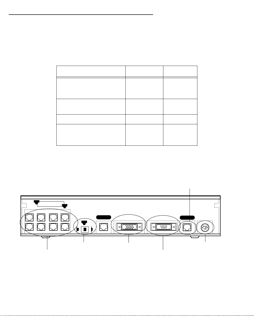
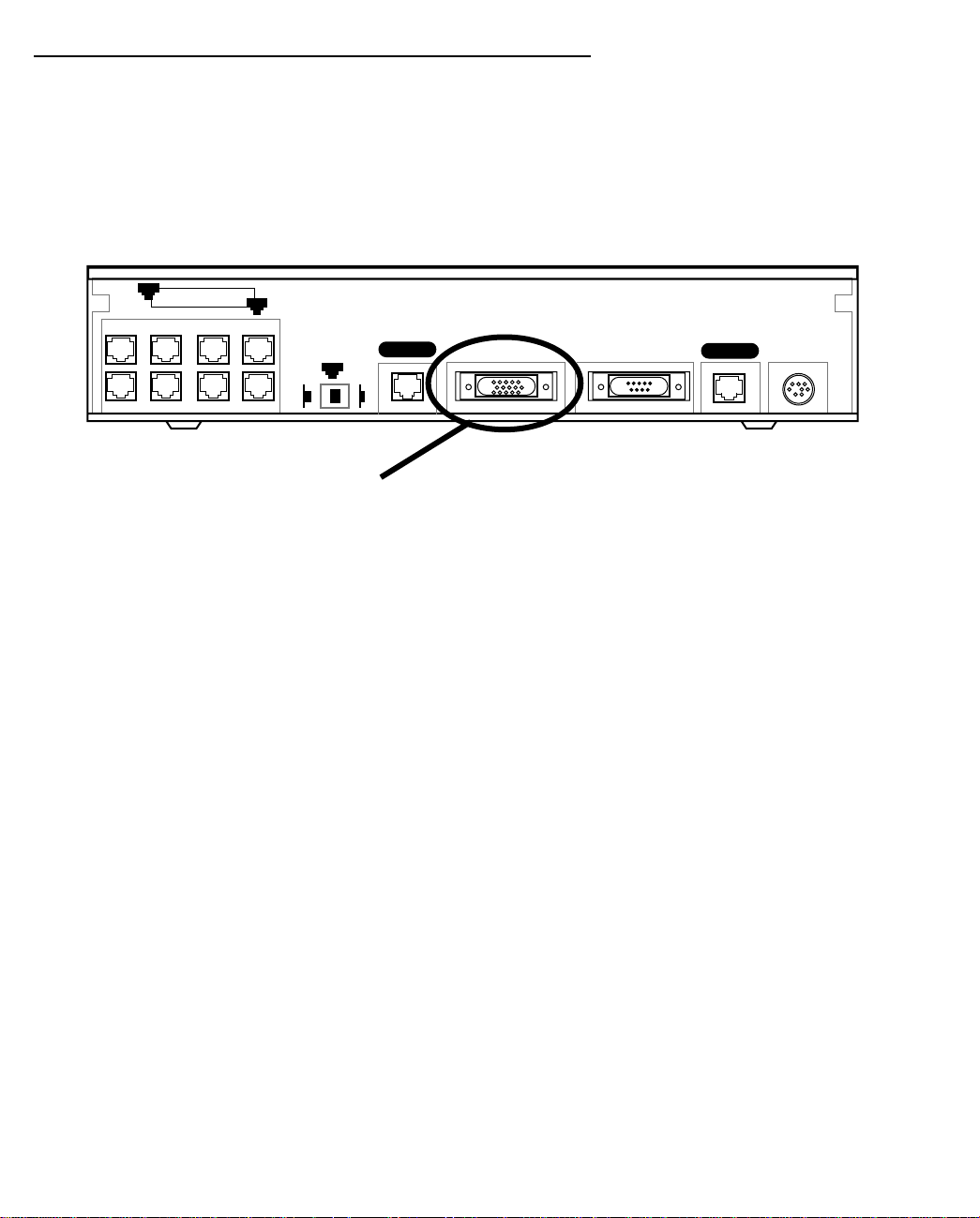
Identify the connectors and attach the cables
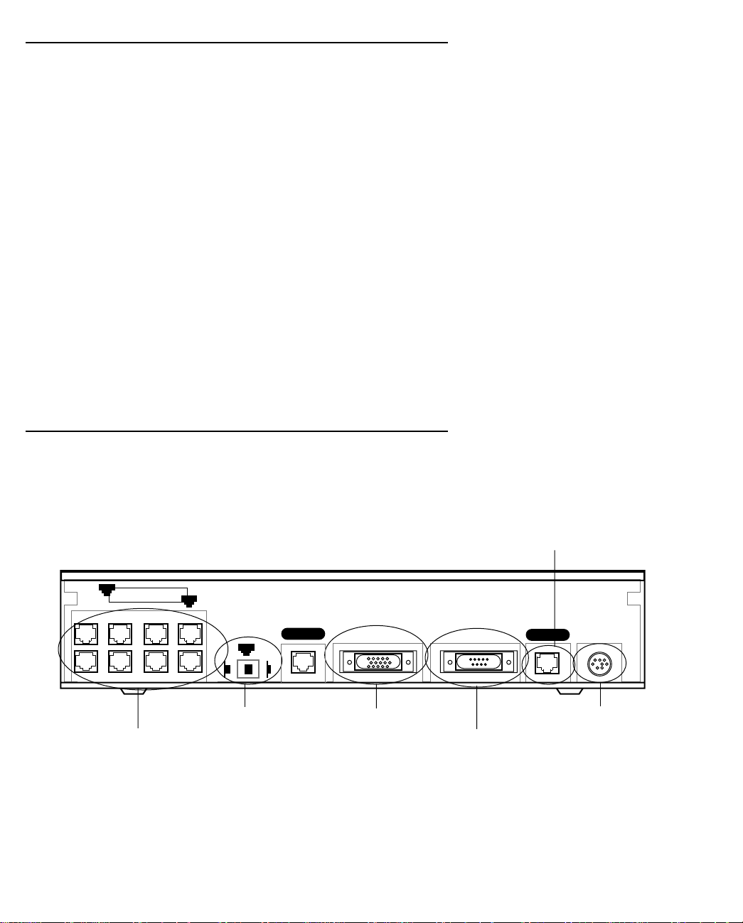
Identify the connectors and switches on the back panel and attach the necessary Netopia Router cables.
The figure below displays the back of the Netopia R9100 Ethernet Router.
Netopia R9100 Ethernet Router back panel
Line 1 port
8
Ethernet
8 port Ethernet hub
1. Connect the mini-DIN8 connector from the power adapter to the power port, and plug the other end into an
electrical outlet.
2. Connect one end of one of the RJ-45 cables to the Line 1 port (not the Line 2 port), and the other end to
your Internet modem’s Ethernet port. DO NOT CONNECT IT DIRECTLY TO A TELCO LINE OUTLET.
1
Normal
1
Uplink
Crossover switch
Line 2
Auxiliary Console Power
Line 1
Auxiliary port
Console port
Power port

Making the Physical Connections 3-3
3. Connect one end of one of the RJ-45 cables to any of the Ethernet hub ports on the router, and the other
end to the Ethernet port of your PC.
(If you are connecting the router to an existing Ethernet hub, use Ethernet port #1 on the router and set the
crossover switch to the Uplink position.)
You should now have: the power adapter plugged in; the Ethernet cable connected between the router and
your computer; and the Line cable connected between the router and your Internet modem.
Netopia R9100 Ethernet Router back panel ports
The following table describes all the Netopia R9100 Ethernet Router back panel ports.
Port Description
Power port A mini-DIN8 power adapter cable connection.
Line port The dedicated Ethernet port for your connection to your Internet connection
device’s Ethernet port. Use Line 1, not Line 2.
Console port A DB-9 console port for a direct serial connection to the console screens. You
can use this if you are an experienced user. See “Connecting a console cable to
your router” on page 6-3.
Auxiliary port An HD-15 auxiliary port for attaching an external modem or the optional
AppleTalk kit.
Crossover switch A crossover switch with Normal and Uplink positions. If you use Ethernet Port
#1 for a direct Ethernet connection between a computer and the router, set the
switch to the Normal position. If you are connecting the router to an Ethernet
hub, use Ethernet port #1 on the router and set the switch to the Uplink
position.
8-port Ethernet hub Eight Ethernet jacks. Y ou will use one of these to configure the Netopia R9100.
For a new installation, use the Ethernet connection. Alternatively, you can use
the console connection to run console-based management using a direct serial
connection. Y ou can either connect your computer directly to any of the Ethernet
ports on the router, or connect both your computer and the router to an existing
Ethernet hub on your LAN.
3-4 User’s Reference Guide
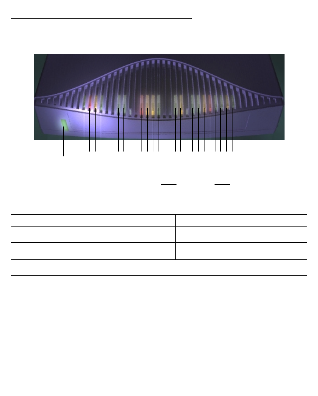
Netopia R9100 Ethernet Router status lights
The figure below represents the Netopia R9100 status light (LED) panel.
Netopia R9100 LED front panel
2 3 4 5 6 7 8 9 10 11 12 13 14 15 16171819 20 21
1
Link/Receive
Power
Ready
Channel 1
Management
WAN 1 WAN 2 Ethernet
Console
Channel 2
Auxiliary
Management
Ready
Channel 1
Channel 2
Traffic
Collision
The following table summarizes the meaning of the various LED states and colors:
When this happens... the LEDs...
The Ethernet WAN interface is operational 3 is green.
The Ethernet WAN interface detects a collision 3 flashes orange.
In normal operation 4 is off.
When data is transmitted or received over the Ethernet link 4 flashes yellow.
Note: 2, 5, 8 – 11 are unused. Also, Console carrier (6) is ignored if the console is not configured for a
remote modem.

Connecting to Your Local Area Network 4-1
CCCChhhhaaaapppptttteeeerrrr 44
CCCCoooonnnnnnnneeeeccccttttiiiinnnngggg ttttoooo YYYYoooouuuurrrr LLLLooooccccaaaallll AAAArrrreeeeaaaa NNNNeeeettttwwwwoooorrrrkk
This chapter describes how to physically connect the Netopia R9100 to your local area network (LAN). Before
you proceed, make sure the Netopia R9100 is properly configured. You can customize the router’s configuration
for your particular LAN requirements using console-based Management (see “Console-Based Management” on
page 6-1).
This section covers the following topics:
■ “Overview” on page 4-1
■ “Readying computers on your local network” on page 4-4
■ “Connecting to an Ethernet network” on page 4-5
■ “Adding an external modem” on page 4-7
■ “Connecting to a LocalTalk network” on page 4-8
44
kk
Overview
You can connect the Netopia R9100 to an IP or IPX network that uses Ethernet.
If you have purchased the AppleTalk feature expansion kit, you can also connect the router to a LocalTalk
network that uses PhoneNET cabling.
Additionally, you can connect an external modem. See “Adding an external modem” on page 4-7.
Caution!
Before connecting the Netopia R9100 to any AppleTalk LANs that contain other AppleTalk routers, you should
read “Routers and seeding” on page 11-3.
See the later sections in this chapter for details on how to connect the Netopia R9100 to different types of
networks.
4-2 User’s Reference Guide
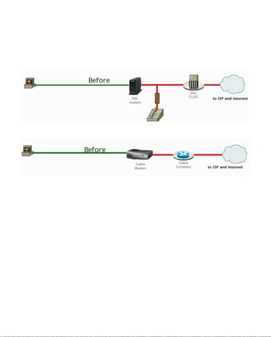
Network Model
The following diagrams illustrate network models for typical deployments of the Netopia R9100 Ethernet Router
as an Internet access device.
Before
With a DSL or cable modem, you can connect a single computer to the Internet.
using a DSL modem
using a cable modem
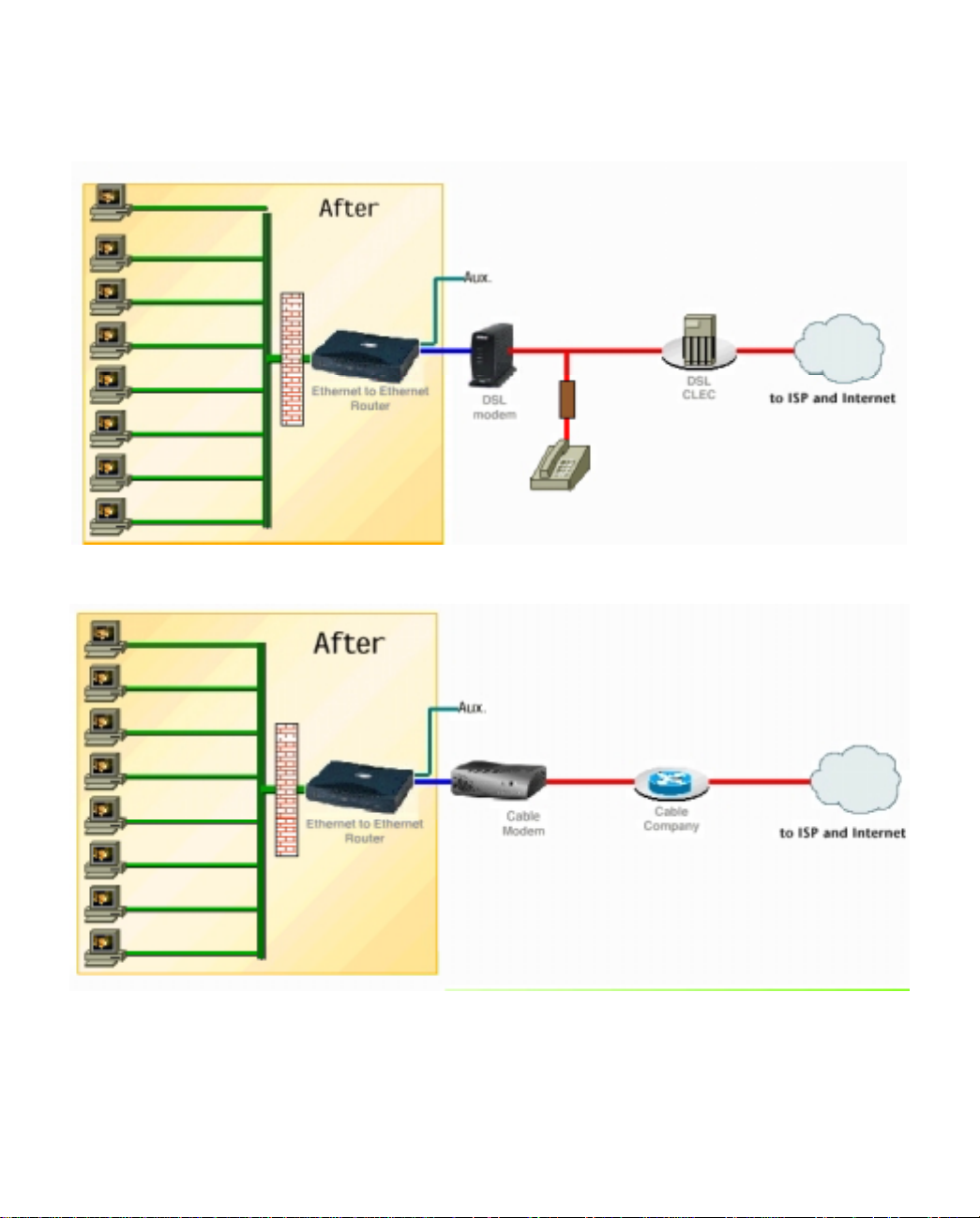
Connecting to Your Local Area Network 4-3
After
Using the Netopia R9100 Ethernet Router, you can connect multiple computers to the Internet with a single
user account.
using a DSL modem with a Netopia R9100
using a cable modem with a Netopia R9100
While this network model is typical, other network models are possible. For example, you may choose to attach
the Ethernet WAN port to an external Ethernet hub connected to a number of workstations.
4-4 User’s Reference Guide
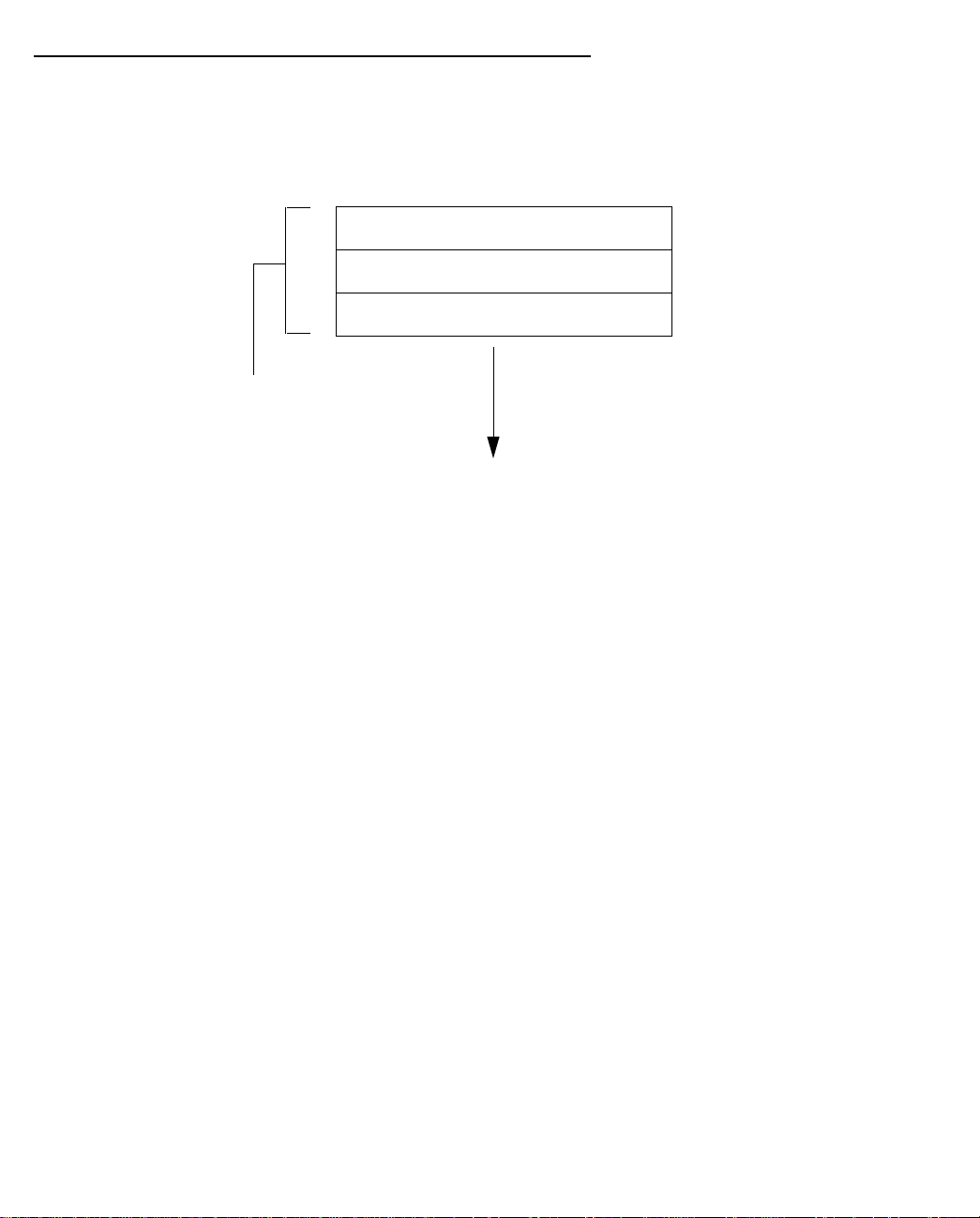
Readying computers on your local network
PC and Macintosh computers must have certain components installed before they can communicate through
the Netopia R9100. The following illustration shows the minimal requirements for a typical PC or Macintosh
computer.
Application software
TCP/IP stack
Ethernet/EtherTalk/LocalTalk Driver
Your PC
or Macintosh
computer
To the Netopia R9100
Application software: This is the software you use to send e-mail, browse the World Wide Web, read
newsgroups, etc. These applications may require some configuration. Examples include the Eudora e-mail client
and the Web browsers Microsoft Internet Explorer and Netscape Navigator.
TCP/IP stack: This is the software that lets your PC or Macintosh communicate using Internet protocols.
TCP/IP stacks must be configured with some of the same information you used to configure the Netopia
R9100. There are a number of TCP/IP stacks available for PC computers. Windows 95 includes a built-in
TCP/IP stack. See “Configuring TCP/IP on Windows 95, 98, or NT” on page 3-2. Macintosh computers use
either MacTCP or Open Transport. See “Configuring TCP/IP on a Macintosh Computer” on page 3-4.
Ethernet: Ethernet hardware and software drivers enable your PC or Macintosh computer to communicate on
the LAN.
EtherTalk and LocalTalk: These are AppleTalk protocols used over Ethernet.
Once the Netopia R9100 is properly configured and connected to your LAN, PC and Macintosh computers that
have their required components in place will be able to connect to the Internet or other remote IP networks.
Connecting to Your Local Area Network 4-5
Connecting to an Ethernet network
The Netopia R9100 supports Ethernet connections through its eight Ethernet ports. The router automatically
detects which Ethernet port is in use.
You can connect either 10Base-T or EtherWave Ethernet networks to the Netopia R9100.
The following table displays some important attributes of these types of Ethernet.
Attribute EtherWave 10Base-T
Max. length of backbone,
branch, or end to end (cable
length)
Cable type
330 feet
(100 meters)
Twisted pair
(10Base-T)
330 feet
(100 meters)
Twisted pair
(10Base-T)
Netopia R9100 port used Ethernet Ethernet
Other restrictions
Maximum 8
devices (daisy
chained)
No daisy
chain
10Base-T
You can connect a standard 10Base-T Ethernet network to the Netopia R9100 using any of its available
Ethernet ports.
Netopia R9100 Ethernet Router back panel
Line 1 port
8
Ethernet
1
Auxiliary Console Power
Line 1
Normal
1
Line 2
Uplink
Crossover switch
8 port Ethernet hub
Auxiliary port
Power port
Console port
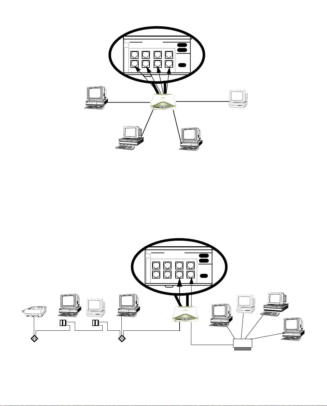
4-6 User’s Reference Guide
The Netopia R9100 in a 10Base-T network
Ethernet
8
4
Normal/
1
To connect your 10Base-T network to the Netopia R9100 through an Ethernet port, use a 10Base-T cable with
RJ-45 connectors.
If you have more than eight devices to connect, you can attach additional devices using either a 10Base-T hub
or an EtherWave daisy chain, or some combination of both.
If you add devices connected through a hub, connect the hub to Ethernet port number 1 on the Netopia R9100
and set the Normal/Uplink switch to Uplink.
When there are no more free ports on the 10Base-T hub, the network can be extended using EtherWave, a daisy-chainable
solution from Farallon.
LaserWriter
EtherWave
Printer Adapter
EtherWave
ISA Card
MacintoshPC PC
EtherWave
NuBus Card
EtherWave
Transceiver
Ethernet
8
4
Normal/
1
10BASE-T
Hub
Connecting to Your Local Area Network 4-7
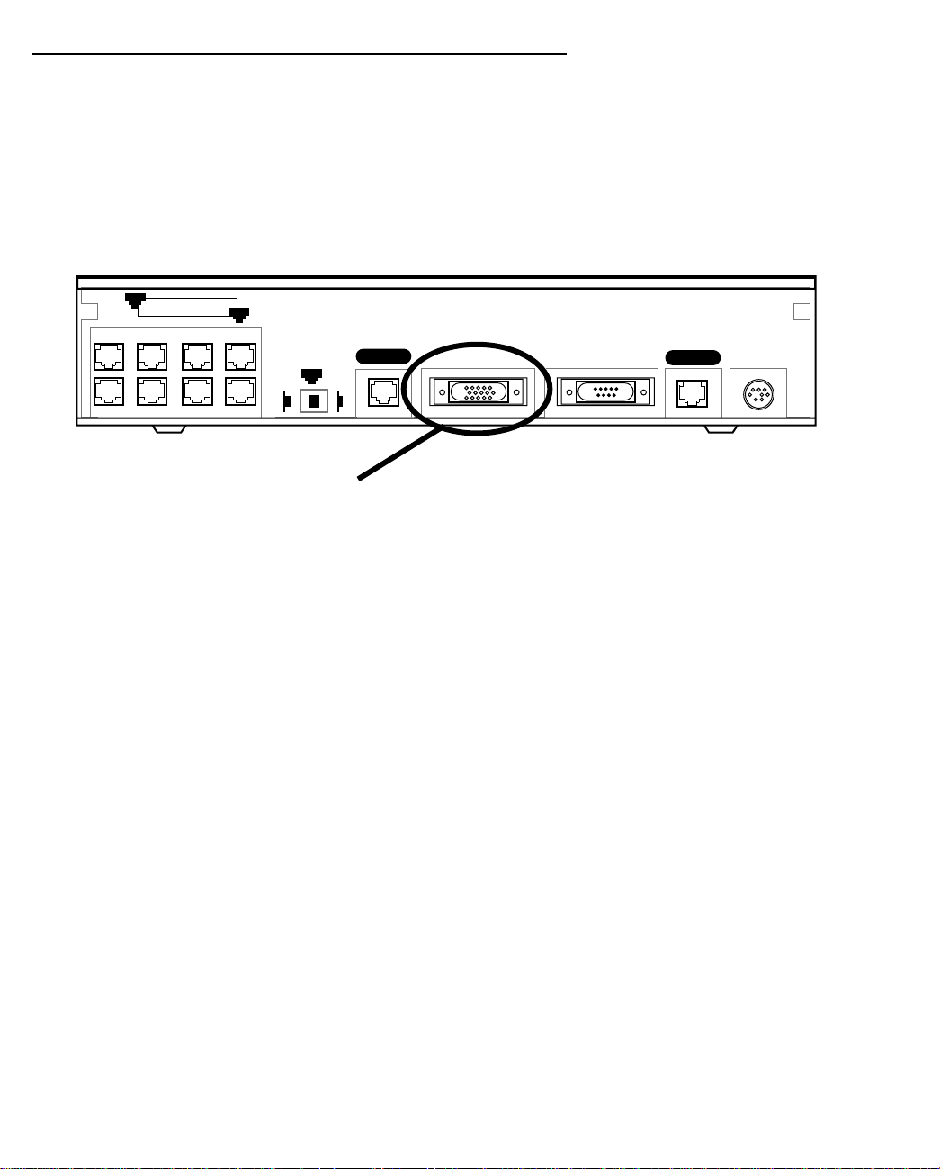
Adding an external modem
You may want to add an external modem to your Auxiliary port. Remote modem terminal emulator setups can
dial in to the modem line and establish a remote console session. This allows Netopia Inc.'s “Up and Running,
Guaranteed!” department or other administrator with the appropriate security to remotely configure your router
for you.
Obtain the special external DB-25 modem cable (Netopia P/N TE6/DB25) either from your reseller or directly
from Netopia.
Netopia R9100 Auxiliary port for connecting an external modem
8
Ethernet
1
Auxiliary Console Power
Line 1
Normal
1
Line 2
Uplink
Auxiliary connection port
HD-15 (female)
By default, the Auxiliary port on your Netopia R9100 is enabled for remote console configuration via an
external asynchronous modem. This means that all you have to do is connect your modem to the Auxiliary port
and configure its settings in the Line Configuration screens under the WAN Configuration menu.
Full Auxiliary Port PPP capabilities can be enabled on a Netopia R9100 as an upgrade option.
For pinout information on the HD-15 to DB-25 modem cable, see “Pinouts for Auxiliary port modem cable,” in
Appendix F, “Technical Specifications and Safety Information.”
4-8 User’s Reference Guide
Connecting to a LocalTalk network
If you have purchased the AppleTalk feature expansion kit, you can also connect the router to an AppleTalk
network that uses either Ethernet or LocalTalk. Refer to the sheet of optional feature set add-ons in your
Netopia R9100 documentation folio.
The AppleTalk feature expansion kit includes a dual RJ-11 PhoneNET connector that attaches to the Auxiliary
port on the Netopia R9100.
Netopia R9100 Auxiliary port for connecting to LocalTalk
8
Ethernet
1
Auxiliary Console Power
Line 1
Normal
1
Line 2
Uplink
Auxiliary connection port
HD-15 (female)
Connect the male HD-15 end of the LocalTalk cable to the Auxiliary port on your Netopia R9100. Connect the
other end of the cable to your LocalTalk network. You can use only one connection on the Auxiliary port. You
cannot use both the PhoneNET connector and an external modem.
If your LocalTalk network is not based on standard PhoneNET cabling, use a PhoneNET-to-LocalTalk adaptor
cable available from Farallon Communications, Inc. Connect the adaptor cable’s RJ-11 connector to the
AppleTalk cable’s PhoneNET connector. Connect the cable’s mini-DIN-3 connector to your LocalTalk network.
Be sure to observe the standard rules governing maximum cable lengths and limits on the number of nodes on
a PhoneNET network. The dual RJ-11 PhoneNET connector allows insertion in the LocalT alk daisy chain or at the
end. If the device is connected at the end of the daisy chain, you must install the accompanying terminator.
 Loading...