

Page 1

fantech
Installation, Operation and Maintenance Manual
Manuel d'installation, d'opération et d'entretien
Manual de Instalación, operación y Mantenimiento
GDC Series
Dehumidier
Déshumidicateur
Deshumidicador
Item #: 405001
Rev Date: 2015-05-12
United States
10048 Industrial Blvd., Lenexa, KS, 66215
Tel.: 800.747.1762 • Fax: 800.487.9915
Canada
50 Kanalflakt Way, Bouctouche, NB, E4S 3M5
Tel.: 800.565.3548 • Fax: 877.747.8116
GDC124CSS • GDC124CS • GDC80CS
Page 2
2
Note Warning/
Important
note
Assembly
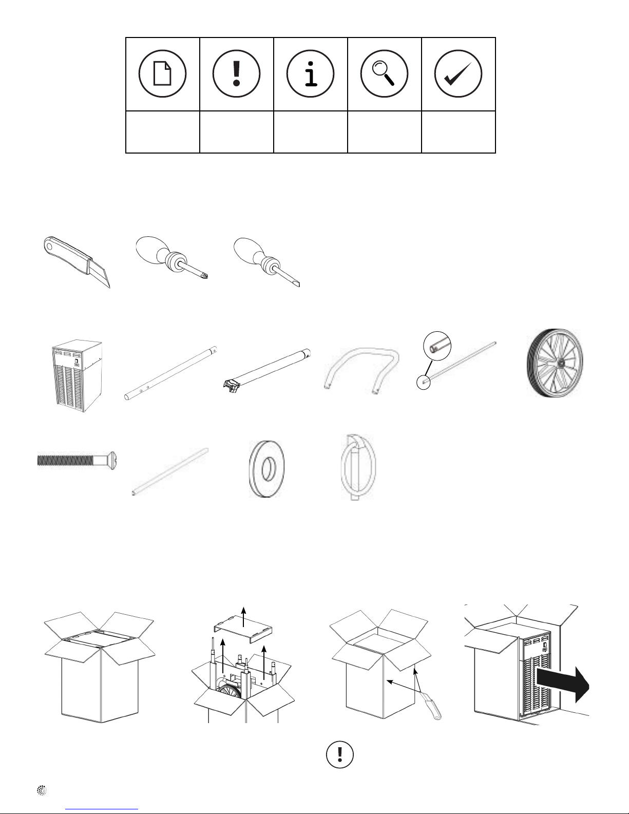
Tools required
Knife Philips Slot Screwdriver
Screwdriver PH-3
Parts
Information Technical
information
Practical tip
Basic Unit (1) Long Tube (2) Short Tube (2) Bent Handle (2) Wheel Axle (1) Wheel (2)
Screw – Handle (6) Hand Axle (1) Washer (2) Lynch Pin (2)
Unpacking
Recycle all cardboard and plastic bags. Keep plastic bags out of the reach of children.
1 Position up and open top. 2 Remove inserts and handle 3 Cut two vertical corners. 4 Remove the unit.
components. Do not damage unit
with knife.
fantech
Page 3
Assembly
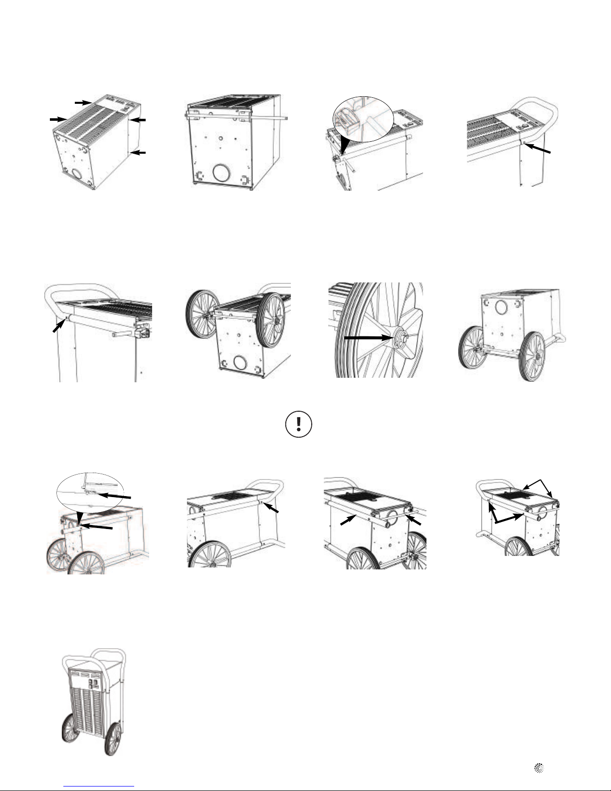
Wheel / Handle Assembly
3
1 Position unit on back. Remove 4
shipping screws and discard.
5 Install one short tube. Install
one handle screw and tighten.
2 Slide wheen axle into wheels
brackets. Offset to one side.
6 Install two wheels on wheel axle.
3 Install one short tube on wheel
axle.
7
7 Install washer and lynch pin to
each wheel axle end.
Personal injury hazard.
Do not place ngers in ring areal.
Ring is spring loaded and closes
with force.
4 Install bent handle on short
tube. Install one handle screw
and tighten.
Lower Door, Second
Handle Assembly
8 Position unit with air lter up.
!
9 Install one long tube, plastic
bushing faces inward. Insert one
handle screw.
Do not tighten.
13 Position unit upright.
Wait 30 minutes before starting to
allow compressor to drain back.
10 Insert bent tube into long tube.
Rotate long tube to align with
cabinet hole and insert one
handle screw.
Do not tighten.
11 Insert hand axle. Insert second
long tube.
12 Insert two handle screws.
Tighten all handle screws.
fantech
Page 4

4
Operation
Built in electrical safety
For your safety and protection this appliance is manufactured with a grounded plug on its power cord. The power cord must be plugged into a properly
grounded receptacle. If a grounded receptacle does not exist, have one installed by a certied electrician. Do not cut or remove the grounding prong on
the power cord plug if equipped. We recommend that this electrical circuit/ receptacle operate under a separate breaker or fuse.
This appliance complies with the suppression requirements of EEC directive 76/889 + 82/499. Recommended limits of use: Temperatures: 0 to 35°C,
Relative humidity: 20 to 80%.
Location of Unit
Minimum 25cm distance from walls. Close all doors and windows. (gure 1)
Initial Star-up
Check the rating plate for the appropriate power supply needed by your unit. Connect the
dehumidier. Ensure that one of the water collection options is working and active. Depress the ON
switch.
Control Panel Settings (gure 2)
(A) ON/OFF Switch
Depress the switch to start or stop the dehumidier. "O" for power off, "I" for power on.
(B) Hour Counter
The counter will accumulate and display the total running hours of the unit in 1/100 of an hour. It
can not be reset to zero. No user input is required.
(C) Pump Purge: (Green button - Some models)
Depressing this button activates the condensate pump. This can be used to empty the pump
reservoir. The button must be held depressed until drain line is clear of water, this is when pump
reservoir is empty. The dehumidier must be switched "ON
".
Figure 1
Figure 2
C
D
A
B
Depress the switch long enough to perform the function. Prolonged depression of the
switches could harm the equipment.
(D) Hot Gas On Demand: (Red button - some models)
Depressing this button activates the hot gas defrost system. This can be used to clear the
evaporator coil of frost if required. The button must be held depressed until the evaporator coil is
cleared of frost. The dehumidier must be switched "ON".
Depress the switch long enough to perform the function. Prolonged depression of the
switches could harm the equipment.
Automatic Defrost Cycle
All units are equipped with an automatically activated (thermostat controlled) Defrost cycle to
automatically defrost the evaporator coils.
fantech
Page 5
Cleaning
DANGER: Electrical shock hazard. Disconnect power before cleaning.
5
Exterior Parts
Use a mild, non-abrasive soap and clean water solution to clean the metal cabinet, handles and
wheels. Wipe dry.
Air Filter
Remove lter. Wash in a mild soap and water. Rinse with clean water. Air dry before reinstalling.
Torn or ripped lters should be replaced with a new lter.
Fan Motor
Does not require lubrication.
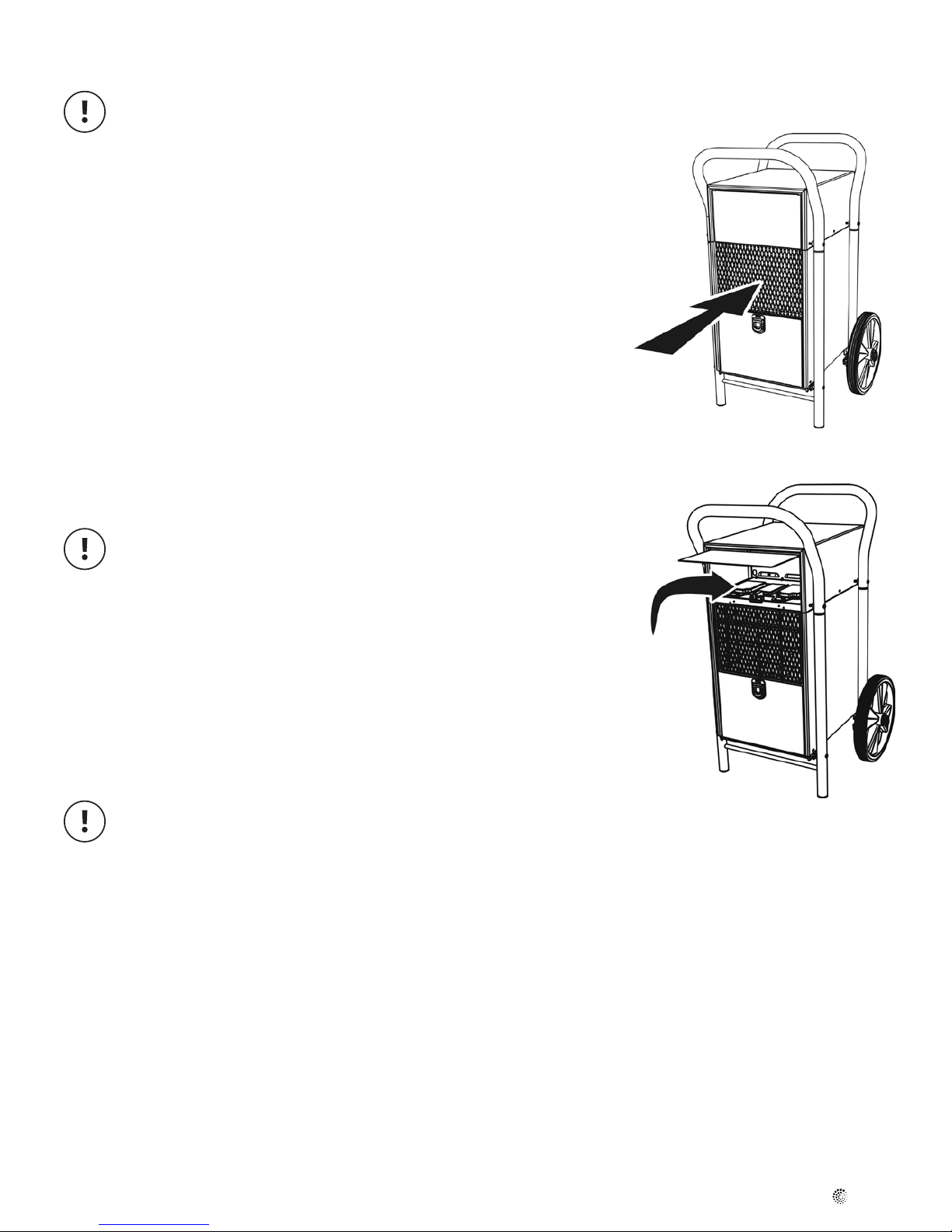
Condenser and Evaporator Coils
1. Light cleaning (gure 3)
Remove the air lter and spray evaporator coil with water.
2. Heavy cleaning (gure 4)
Open upper door. Remove plastic cleanout by pushing the two locking tabs and lifting. Spray water
at coils. Replace the cleanout.
A qualied refrigeration technician must service all refrigerant leaks.
If power to the unit is disconnected or unit is turned off, allow 3 minutes before restarting
the dehumidier. This allows the internal pressures to equalize.
Figure 3
Figure 4
Storage
Single unit
It is best to cover the unit if extended storage periods are contemplated. Remove all water in
collection system.
Stacking two units
This dehumidier can be stacked two high.
An assembled unit weighs 39 kgs. Position on a level surface.
Personal injury hazard. Use two individuals to lift. Maximum stacking height: 2 units.
fantech
Page 6
6
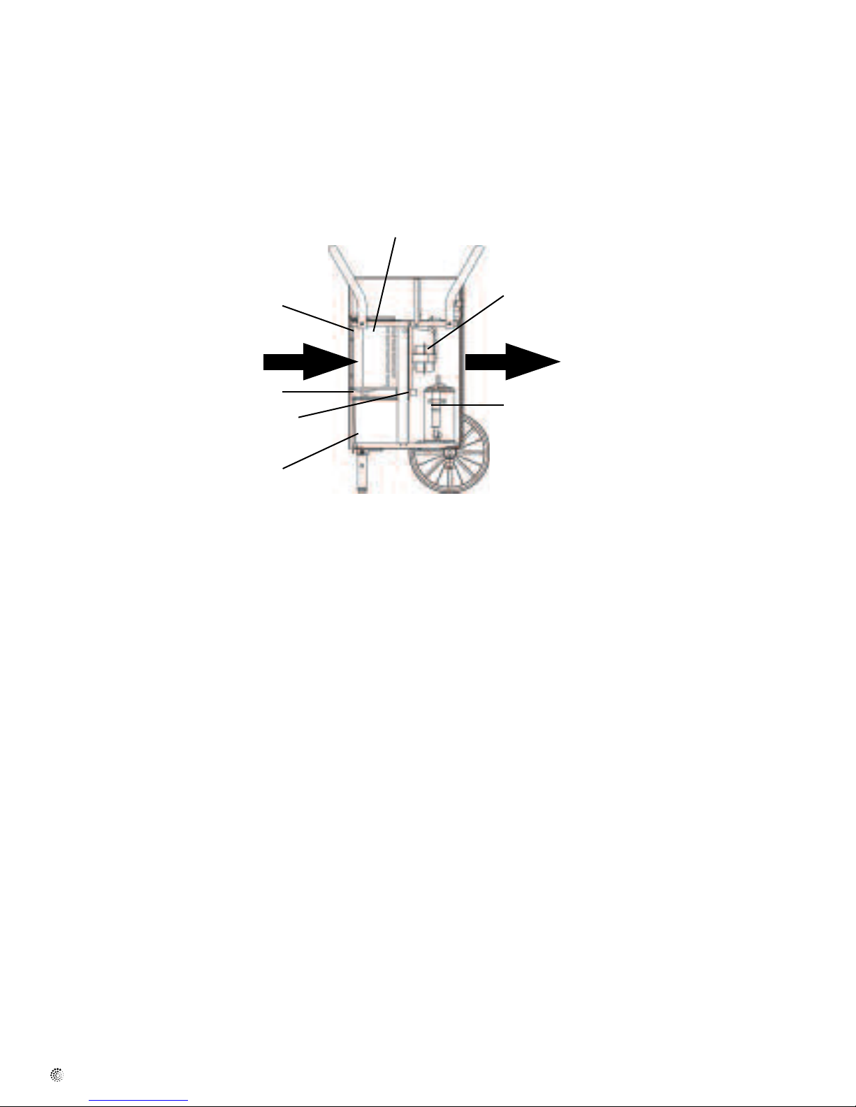
How a Dehumidifier Works
The dehumidier removes moisture from the air by passing the moist air over a cold dehumidifying coil. The moisture condenses out of the air on this
coil and then drains from the coil into a bucket. A dehumidier reduces the relative humidity of the surrounding air two ways. The removal of moisture
from the air (as just described) reduces its humidity. The relative humidity of the air is further reduced by heating as the dry air is discharged over
the condenser and out the front. The air is actually heated several degrees in this process. It is normal for the surrounding air to slightly increase in
temperature as the dehumidier operates.
Condenser
Air Circulating Fan
Evaporator
Humid Air In Dry Air Out
Continuous Drain Connector
Float
Condensate Pump
Compressor
Before Calling for Service
Perform these simple checks
Condition – Unit is not working
• Is the dehumidier connected to a live and correct voltage electrical supply?
• Is there a blown fuse or tripped circuit breaker? (Check the outlet with another appliance).
• Is the Power Switch pushed to the "I" position?
• Is the water container (if used) full and requires emptying?
• Is the water lever plastic oat freely handing inside bucket (if bucket is used), or hangs freely in air (if no bucket)?
Condition – Moisture removal seems insufcient
• Are the dehumidier's vents and air lter clear of obstructions and dirt?
• Does the location selected present sufcient airow around the unit?
fantech
Page 7

7
Note Avertissement
Information Information
/ Note
importante
Assemblage
Outils
Couteau Tournevis Tournevis plat
cruciforme (taille PH3)
Pièces
technique
Conseil
pratique
Unité de base (1) Tubes longs (2) Tubes courts (2) Poignées courbées (2) axe des roues (1) Roues (2)
Vis des poignées (6) Axe de la poignée (1) Rondelles (2) Tiges des roues (2)
Consignes de déballage
Recyclez tous les cartons et tous les sacs en plastique. Gardez les sacs en plastique hors de la portée des enfants.
1 Mettez debout et ouvrez le haut.
2 Enlevez les emballages en car-
ton et les pièces des poignées.
3 Coupez deux angles verticaux.
Ne détériorez pas
l'appareil avec le
couteau
4 Enlevez l'appareil.
fantech
Page 8

8
Assemblage
Assemblage des roues et des poignées
1 Placez l'appareil sur le dos.
Enlevez les quatre vis d'expédition et jetez-les
5 Installez un tube court. Installez
une vis de poignée et serrez-la
2 Glissez l'axe des roues dans les
supports des roues. Déportez
l'axe d'un côté
6 Installez les deux roues sur l'axe
des roues.
3 Installez un tube court sur l'axe
des roue
7
7 Installez une rondelle et une tige
des roues à chaque extrémité
de l'axe des roues.
Risque de blessure. Ne placez pas
vos doigts dans l'anneau. L'anneau
est équipé d'un ressort et se
ferme avec force.
4 Installez la poignée courbée sur
le tube court. Installez une vis
de poignée et serrez-la.
Assemblage de la porte inférieur,
et la deuxième poignée
8 Placez l'appareil avec le ltre à
air vers le haut
!
9 Installez le long tube. Prenez note:
la bague en plastique fait face
au caisson. Insérez une vis de
poignée.
Ne serrez pas la vis
13 Mettez l'appareil debout
Attendez 30 minutes avant de mettre en marche
an de drainer l'huile du compresseur.
fantech
10 Insérez le tube courbé dans le
tube long. Pivotez le tube long
an de l'aligner avec le trou de
caisson et insérez une vis de
poignée.
Ne serrez pas la vis
11 Insérez l'axe de la poignée.
Insérez le deuxième tube long.
12 Insérez deux vis de poignée.
Serrez toutes les vis de
poignée.
Page 9

Fonctionnement
Dispositif de sécurité électrique intégré
Pour votre sécurité et votre protection, cet appareil comporte une che de terre. L'appareil doit etre branché dans une prise mise a la terre, installé
selon les normes de sûreté régionaux. S'il n'existe pas de prise mise à la terre, faites-en installer une par un électricien agréé. Ne coupez pas et
n'enlevez pas la broche de mise à la terre sur la che du cordon d'alimentation. Nous recommandons que ce circuit électrique / cette prise fonctionne
avec un coupe-circuit ou un fusible séparé.
Cet appareil est conforme aux exigences de la suppression de la directive CEE 76/889 + 82/499. Limite d'utilisation recommandées: Température de
0 à 35C, Humidité relative: 20 à 80%.
9
Emplacement de l'appareil
À 25 cm des murs. Fermez toutes les portes et toutes les fenêtres. (gure 1)
Démarrage initial
Vériez la plaque signalétique pour l'alimentation électrique appropriée requise par votre appareil.
Branchez le déshumidicateur. Assurez-vous qu'une des options de collecte d'eau fonctionne et est
activée. Appuyez sur l'interrupteur MARCHE.
Réglages du panneau de commande (gure 2)
(A) Interrupteur MARCHE / ARRÊT
Appuyez sur l'interrupteur pour mettre en marche ou arrêter le déshumidicateur. « O » pour l'arrêt
et « I » pour la mise en marche.
(B) Compteur d'heures
Le compteur accumulera et afchera le nombre total d'heures de fonctionnement de l'appareil en
1/100 par heure. Il ne peut pas être remis à zéro. Aucune donnée de l'utilisateur est requise.
(C) Purge de la pompe: (bouton vert-optionnel)
En appuyant sur ce bouton, on active la pompe à condensât. Ceci peut servir à vider le réservoir
de la pompe. Le bouton doit être maintenu enfoncé jusqu'à ce que la tuyauterie de vidange soit vide
d'eau. C'est alors que le réservoir de la pompe est vide. Le déshumidicateur doit être en position
« ON».
Figure 1
Figure 2
C
D
A
B
Maintenir le bouton enfoncé juste assez longtemps pour effectuer la fonction. Un
enfoncement prolongé des boutons pourrait endommager 'équipement.
(D) Gaz chaud à la demande: (bouton rouge-optionnel)
En appuyant sur ce bouton, on active le système de dégivrage à gaz chaud. Ceci peut servir à
débarrasser le serpentin 'évaporateur du givre au besoin. Le bouton doit être maintenu enfoncé
jusqu'à ce que le serpentin d'évaporateur soit débarrassé du givre. Le déshumidicateur doit être
en position « ON ».
Maintenir le bouton enfoncé juste assez longtemps pour effectuer la fonction. Un
enfoncement prolongé des boutons pourrait endommager l'équipement.
Cycle de dégivrage automatique
Tous les appareils sont équipés d'un cycle de dégivrage à déclenchement automatique (contrôlé par
thermostat) an de dégivrer automatiquement les serpentins de l'évaporateur.
fantech
Page 10

10
Nettoyage
DANGER: Risque de choc électrique. Débranchez avant de nettoyer.
Parties extérieures
Utilisez une solution de savon doux, non abrasif et d'eau propre pour nettoyer les parties du
caisson en métal peint, les poignées et les roues. Essuyez-les.
Filtre à air
Enlevez le ltre. Lavez-le avec du savon doux et de l'eau tiède. Rincez avec de l'eau propre. Laissezle sécher à l'air libre avant de le réinstaller. Les ltres déchirés ou endommagés doivent être
remplacés par un nouveau ltre.
Moteur du ventilateur
N'a pas besoin de lubrication.
Serpentins du condensateur et de l'évaporateur
1. Nettoyage léger (gure 3)
Enlevez le ltre à air et vaporisez de l'eau sur le serpentin de l'évaporateur.
2. Nettoyage important (gure 4)
Ouvrez la porte supérieure. Enlevez la porte de nettoyage en plastique en poussant sur les deux
pattes de verrouillage et en la soulevant. Vaporisez de l'eau sur les serpentins. Remettez la porte
de nettoyage en place.
Un technicien en réfrigération qualié doit assurer l'entretien de toutes les fuites de
frigorigène.
Figure 3
Figure 4
Si l'appareil a été debranché ou mis hors tension, attendez trois minutes avant de remettre
le déshumidicateur en marche. Cela permet aux pressions internes de s'égaliser
Entreposage
Un seul appareil
Il est préférable de couvrir l'appareil si vous prévoyez de l'entreposer pendant une période de
temps prolongée. Enlevez toute l'eau dans le système de collecte.
Empilage de deux appareils
Deux déshumidicateurs peuvent être empilés en hauteur. Un appareil assemblé pèse 39 kg.
Risque de blessures. Utilisez deux personnes pour soulever l'appareil. Hauteur maximale
d'empilage: 2 appareils.
fantech
Page 11

11
Comment fonctionne un déshumidificateur
Le déshumidicateur élimine l'humidité de l'air en faisant circuler l'air humide sur un serpentin froid asséchant. L'humidité se condense sur le serpentin
et s'égoutte ensuite du serpentin dans un réservoir. Le déshumidicateur réduit l'humidité relative de l'air ambiant de deux manières. L'élimination
de la vapeur dans l'air (comme nous venons de la décrire) réduit son humidité. L'humidité relative atmosphérique est également réduite en chauffant
l'air chaud rejeté du condenseur vers l'avant de l'appareil. En fait, l'air est chauffé de plusieurs degrés au cours de ce processus. Il est normal que la
température de l'air ambiant augmente légèrement lorsque le déshumidicateur fonctionne.
Condenseur
Ventilateur
Évaporateur
Entrée de l'air humide Sortie de l'air sec
Raccord permanent du drain
Floteur
Réservoir
Compresseur
Avant de demander les services d'un technicien
Procédez à ces vérications simples.
Problème – l'appareil ne fonctionne pas
• Le déshumidicateur est-il branché à une alimentation électrique sous tension et au voltage approprié?
• Y a-t-il un fusible grillé ou un coupe-circuit sauté? (Vériez le fonctionnement de la prise avec un autre appareil.)
• L'interrupteur de mise en marche est-il poussé en position "I"?
• Le réservoir d'eau (s'il est utilisé) est-il plein et a-t-il besoin d'être vidé?
• Le otteur de niveau d'eau en plastique est-il toujours accroché et peut-il bouger librement à l'intérieur du réservoir (si le réservoir est utilisé) ou
dans l'air (s'il n'y a pas de réservoir)?
Problème – l'élimination de l'humidité semble insufsante
• Les évents et le ltre à air du déshumidicateur sont-ils libres de toute obstruction et de toute saleté?
• L'appareil sélectionné offre-t-il une circulation d'air sufsante autour de l'appareil?
fantech
Page 12

12
Nota Advertencia/
Información Información
Nota
importante
Montaje
Herramientas
Cuchillo Destornillador de Destornillador de pala
estrella (tamaño PH3)
Partes
técnica
Consejo
práctico
Unidad básica (1) Tubo largo (2) Tubo corto (2) Asa curvada (2) Eje de rueda (1) Rueda cantidad (2)
Tornillos de asa (6) Eje mano (1) Arandela (2) Pasador rueda (2)
Instrucciones de desembalaje
Recicle el cartón y las bolsas de plástico. Mantenga las bolsas de plástico alejadas del alcance de los niños.
1 Coloque boca arriba y abra la
zona superior.
fantech
2 Extraiga las sujeciones de
cartón y los componentes de
las asas.
3 Corte dos esquinas verticales
No dañe la unidad con el
cuchillo.
4 Extraiga la unidad
Page 13

Asamblea
Montaje de ruedas y asas
13
1 Apoye la unidad sobre su
parte trasera. Desatornille
los 4 tornillos de transporte y
deséchelos.
5 Instale uno de los tubos cortos.
Atornille rmemente uno de los
tornillo del asa.
2 Introduzca el eje de la rueda
dentro de los anclajes de las
ruedas. Ontrapese en uno de
los lados.
6 Inserte las dos ruedas en el eje
de la rueda.
3 Coloque uni de los tubos cortos
en el eje de la rueda.
7
7 Coloque la arandela y el pasador
de la rueda en cada uno de los
extremos del eje
Peligro de daño físico. no toque
con los dedos en la zona del anillo.
El anillo viene equipado con un
resorte y se cierra con fuerza.
4 Coloque el asa curvada en el
tubo corto. Atornille rmemente
uni de los tornillos del asa.
Montaje de la puerta
inferor, la segunda asa
8 Coloque la unidad con el ltro
de aire hacia arriba.
!
9 Coloque un tubo largo. La parte
de plástico mira hacia la caja
Comience a atornillar uno de los
tornillos de asa pero no apriete
13 Coloque la unidad en posición vertical.
Espere 30 minutos antes de ponerla en funcianamiento para
que el aceite del compresor se aposente.
10 inserte el asa curvada en
el tubo largo. Gire el tubo
largo para que coincida con el
agujero de la caja y atornilla un
tornillo de asa. Atornille sin
apretar
11 Coloque el eje de mano.
Coloque el segundo tubo largo.
Coloque el eje en el primer
tubo largo.
12 Atornille dos tornillos de asa.
Apriete todos los tornillos de
asa.
fantech
Page 14

14
Funcionamiento
Protección eléctrica incorporada
Para proporcionarle mayor seguridad y protección esta unidad está equipada con una toma de tierra en el cable de alimentación. El cable debe
enchufarse en un receptáculo con toma de tierra apropiada. Si no dispone de receptáculo con toma de tierra, pida a un electricista autorizado que
se lo instale. No corte o elimine la patilla de toma de tierra de la clavija si así se suministra. Le recomendados que utilice este circuito/ receptáculo
eléctrico con un fusible o diferencial separado.
Colocación del aparato
Deje 25cm desde las paredes. Cierre todas las puertas y ventanas. (gura 1)
Primeros pasos
Compruebe la etiqueta para saber cuál es el tipo de alimentación eléctrica apropiado para la
unidad. Conecte el deshumidicador. Asegúrese de que las opciones de acumulación de agua
funcionan y están activas. Apriete el botón ON.
Panel de control (gura 2)
(A) Conmutador ON/OFF
Apriete el conmutador para arrancar o detener el deshumidicador. "O" para apagado e "I" para
encendido.
(B) Contador horario
El contador sumará y mostrará el número total de horas de funcionamiento de la unidad en 1/100
de hora. No puede reiniciarse. No es necesaria ninguna intervención por parte del usuario.
(C) Bomba de depuración (Botón verde-opcional)
Si se aprieta este botón se activa la bomba de condensación. Puede seguir este procedimiento
para vaciar la reserva de la bomba. Debe mantenerse el botón apretado hasta que no se
muestre agua en la línea de drenaje. Esto indica que la reserva de la bomba se ha vaciado. El
deshumidicador debe estar encendido (ON).
Figure 1
Figure 2
C
D
A
B
Mantenga apretado sólo el botón suciente tiempo para completar la operación de
vaciado. Si mantiene apretados los botones más tiempo del necesario podría dañar el
equipo.
(D) Sistema de aire caliente: (Botón rojo-opcional).
Si aprieta este botón activará el sistema de descongelación por aire caliente. Puede utilizarlo para
eliminar la escarcha del serpentín evaporador cuando sea necesario. Mantenga el botón apretado
hasta que el serpentín evaporador no tenga escarcha. El deshumidicador debe estar encendido
(ON).
Mantenga apretado sólo el botón suciente tiempo para completar la operación de
eliminación de escarcha. Si mantiene apretados los botones más tiempo del necesario
podría dañar el equipo.
Ciclo automático de descongelación
Todas las unidades se suministran con un ciclo de descongelación automático (controlado por
termostato) que descongela automáticamente las espirales del evaporador.
fantech
Page 15

Limpieza
PELIGRO DE DESCARGA ELÉCTRICA. Desconecte el aparato de la corriente antes de su
limpieza.
Partes externas
Utilice un jabón suave y no abrasivo en solución de agua clara para la limpieza de la pintura de la
caja metálica, las asas y las ruedas. Seque con un trapo.
Filtro del aire
Saque el ltro. Lávelo con agua y jabón suave. Aclare con agua. Déjelo secar al aire antes de
proceder de nuevo a su instalación. Los ltros rotos o con desgarros deben reemplazarse por
ltros nuevos.
Motor del ventilador
No precisa lubricación
Espirales del condensador y del evaporador
1. Limpieza supercial (gura 3)
Saque el ltro del aire y rocíe la espiral del evaporador con agua.
2. Limpieza profunda (gura 4)
Abra la puerta superior. Para sacar las piezas plásticas de limpieza presione las dos lengüetas y
luego levántelas. Rocíe con agua las espirales. Vuelva a colocar las piezas.
15
Figura 3
Figura 4
Sólo un técnico en refrigeración autorizado debe arreglar las fugas de refrigerante.
Si la unidad está desenchufada o apagada, espere 3 minutos antes de reiniciar su
funcionamiento. De este modo se permite que la presión interna se equilibre.
Almacenaje
Una sola unidad
Es recomendable cubrir la unidad si se va a almacenar durante un tiempo prolongado. Elimine el
agua del sistema.
Almacenamiento de dos unidades
Pueden almacenarse dos unidades una sobre la otra. Una unidad montada tiene un peso de 39 kg.
Son precisas dos personas para ele-var el aparato. Altura máxima de almacenaje: 2
unidades
fantech
Page 16

16
Cómo funciona un deshumidificador
Para eliminar la humedad del aire, el deshumidicador la hace pasar por una espiral fría. La humedad del aire se condensa en la espiral y luego
desagua en un recipiente. El deshumidicador reduce la humedad relativa del aire circundante de dos formas distintas. La eliminación del vapor de
agua en el aire (tal y como se acaba de describir) reduce la humedad. La humedad se reduce aún más por calentamiento, en el momento en el que el
aire seco se expulsa al condensador y sale por la parte frontal. El aire se calienta varios grados durante este proceso. Es normal que el aire circulante
incremente levemente su temperatura cuando el deshumidicador se encuentra en funcionamiento. Este efecto de calentamiento disminuye aún más el
efecto de eliminación de humedad
Condensador
Ventilador de circulación de aire
Evaporador
Entrada de aire húmedo Salida de aire caliente
Conector de drenaje continuo
Flotador
Recipiente
Compresor
Antes de solicitar asistencia técnica
Compruebe estos sencillos pasos
Síntoma – La unidad no funciona
• ¿El deshumidicador está enchufado a una fuente de alimentación en funcionamiento y del voltaje adecuado?
• ¿Hay algún fusible fundido o algún diferencial desconectado? (Compruebe el enchufe con otro electrodoméstico).
• ¿Se encuentra el botón de encendido en la posición "I"?
• Si existe, ¿está el contenedor de agua lleno y es preciso vaciarlo?
• Si se utiliza un recipiente, ¿está el otador plástico de nivel de agua colgando sin sujeción? Si no hay recipiente, ¿está colgando en el aire sin
sujeción?
Síntoma – El aparato ne elimina suficiente humedad
• ¿Los conductos de ventilación y el ltro de aire están limpios y no obstruidos po el polvo?
• ¿Hay suciente circulación de aire alrededor de la unidad en el lugar escogido?
fantech
Page 17

WARRANTY
One (1) Year Warranty
This warranty supersedes all prior warranties
17
WARRANTY - ONE YEAR
This product is warranted against defects in material and workmanship for
a period of one year from the date of purchase by the original purchaser.
During this period, all parts and labor will be provided at no cost.
Consumable parts (ie: light bulbs and filters) are not warranted or
guaranteed for any length of time. This warranty is non transferable.
ADDITIONAL SIX YEAR WARRANTY
For a period of six years following the ONE YEAR WARRANTY components
of the sealed system are warranted against defects in material. Parts will
be supplied (freight prepaid) free of charge. Installation labor is not
covered. This warranty is non transferable.
LIFETIME WARRANTY ON ROTOMOLDED HOUSING
The Rotomolded housing of this product carries a lifetime warranty. This
warranty is non transferable.
NOTICE
1. This warranty applies only to the original purchaser and applies only
within the boundaries of CANADA and CONTINENTAL USA.
2. This is the only warranty of the dealer and Fantech Limited. for the
above mentioned product and no other warranty or condition, expressed
or implied shall apply, except where specifically excluded by law.
3. The original purchaser should complete this warranty form and retain it
in the event warranty service is required.
4. Proof of purchase date will be required for warranty claims. Please
retain bills of sale for proof.
5. Some states do not allow the exclusion or limitation of incidental or
consequential damages, so the above limitation or exclusion may not
apply to you. This warranty gives specific legal rights, and the purchaser
may have other rights which vary from state to state. For more
information regarding legal rights the purchaser may contact the local
or state consumer affairs office or the appropriate state Attorney
General.
GENERAL PROVISIONS
No warranty or insurance herein contained or set out shall apply when
damage or repair is caused by any of the following:
1. Power failure.
2. Damage in transit or when moving the appliance.
3. Improper power supply such as low voltage, defective house wiring or
inadequate fuses.
4. Accident, alteration, abuse or misuse of the appliance such as
inadequate air circulation in the room or abnormal operating
conditions, (extremely high or low room temperatures).
5. Fire, water, damage, theft, war, riot, hostility, acts of God such as
hurricanes, floods, etc.
For information concerning your warranty, contact:
In Canada
Fantech
50 Kanalflakt Way,
Bouctouche, NB E4S 3M5
Phone: 800.565.3548; 506.743.9500
Fax: 877.747.8116; 506.743.9600
In Continental USA
Fantech
10048 Industrial Blvd.
Lenexa, KS 66215
Phone: 800.747.1762; 913.752.6000
Fax: 800.487.9915; 913.752.6466
email: service@fantech.net
fantech
Page 18

18
GARANTIE
Garantie de 1 ans
Cette garantie remplace toutes les garanties précédentes.
GARANTIE – UN AN
Ce produit est garanti contre tous les défauts de pièces et de maind'oeuvre pour une période d'un an à compter de la date d’achat par
l’acheteur initial. Au cours de cette période, toutes les pièces et la maind'oeuvre seront fournies sans frais. Les pièces consommables (par
exemple, les ampoules électriques et les filtres) ne font l’objet d’aucune
garantie. Cette garantie n’est pas transférable.
GARANTIE SUPPLÉMENTAIRE DE SIX ANS
Les composantes du système scellé sont garanties contre les défauts de
matériaux pour la période de six ans qui suit l’expiration de la GARANTIE
D'UN AN. Les pièces seront fournies (frais de port payés d’avance) sans
frais. Les frais de main-d'oeuvre pour l’installation ne sont pas couverts.
Cette garantie n’est pas transférable.
GARANTIE À VIE SUR BOÎTIER ROTOMOULÉ
Le boîtier rotomoulé de ce produit est garanti à vie. Cette garantie n'est
pas transférable.
AVIS
1. Cette garantie ne s’applique qu’à l’acheteur initial et seulement dans les
limites des frontières du CANADA et des ÉTATS-UNIS CONTINENTAUX.
2. La présente constitue la seule garantie offerte par le détaillant et
Fantech Limited pour le produit susmentionné et aucune autre garantie
ou condition, explicite ou implicite, ne s’appliquera, à moins d’exclusion
contraire expressément imposée par la loi.
3. L’acheteur initial devrait remplir le présent formulaire de garantie et le
conserver pour le cas où des réparations couvertes par la garantie
seraient nécessaires
4. La date de la preuve d’achat sera exigée pour les réclamations au titre
de la garantie. Veuillez conserver les actes de vente à titre de preuve.
5. Certains États ne permettent pas l’exclusion ou la limitation des
dommages consécutifs ou indirects, de sorte que la limitation ou
l’exclusion ci-dessus pourrait ne pas s’appliquer à vous. Cette garantie
donne des droits légaux particuliers à l’acheteur et celuici peut avoir
d’autres droits qui varient d’un État à l’autre. Pour de plus amples
informations concernant ses droits, l’acheteur peut communiquer avec
le bureau de la protection du consommateur local ou de l’État ou le
secrétaire à la Justice de l’État concerné.
DISPOSITIONS GÉNÉRALES
Aucune garantie ou assurance contenue ou exprimée dans les présentes
ne s’appliquera lorsque les dommages ou le besoin de réparations sont la
conséquence d’une ou plusieurs des choses suivantes:
1. Panne d’électricité.
2. Dommages subis au cours du transport ou du déplacement de
l’appareil.
3. Alimentation électrique inappropriée (par exemple, faible tension,
câblage domestique défectueux ou fusibles inadéquats).
4. Accident, modification, mauvaises conditions de fonctionnement ou
mauvaise utilisation de l’appareil, des suites par exemple d’une
circulation inadéquate de l’air dans une pièce ou de conditions de
fonctionnement anormales (températures ambiantes extrêmement
élevées ou basses).
5. Dommages par le feu ou l’eau, vol, guerre, émeute, hostilités, cas
fortuits comme les ouragans, les inondations, etc.
Pour des renseignements concernant votre garantie, contactez:
Au CANADA
Fantech
50 Kanalflakt Way,
Bouctouche, NB E4S 3M5
Phone: 800.565.3548; 506.743.9500
Fax: 877.747.8116; 506.743.9600
Aux ÉTATS-UNIS continentaux
Fantech
10048 Industrial Blvd.
Lenexa, KS 66215
Phone: 800.747.1762; 913.752.6000
Fax: 800.487.9915; 913.752.6466
email: service@fantech.net
fantech
Page 19

GARANTIA
Garantia por un (1) Años
Esta garantia de sin efecto cualquier otra garantia anterior
19
GARANTÍA DE UN AÑO
Se garantiza este producto contra defectos de fabricación y materiales por
un periodo de un año a contar a partir de la fecha de compra del
comprador original. Todas las partes y la mano de obra estarán cubiertas
sin coste alguno durante este periodo. Las partes de reemplazo habitual
(bombillas y filtros, por ejemplo), no están cubiertas por la garantía ni se
garantizan durante periodo de tiempo alguno. Esta garantía no puede
transferirse.
GARANTÍA ADICIONAL DE SEIS AÑOS
Durante un periodo de seis años a contar desde la finalización de la
GARANTÍA DE UN AÑO, los componentes del sistema precintado están
cubiertos en caso de que las piezas mostraran algún defecto. Se
entregarán las piezas de manera gratuita (tras prepago de costos de
envío). Los costes de mano de obra para la instalación no están cubiertos
por la garantía. Esta garantía no puede transferirse.
GARANTÍA DE POR VIDA EN LA CAJA ROTOMOLDEADO
La caja rotomoldeado de este producto cuenta con una garantía de por
vida. Esta garantía no es transferible.
AVISO
1. Esta garantía es válida solamente para el comprador original y dentro
de las fronteras de Canadá y la parte continental de Estados Unidos.
2. Esta es la única garantía del vendedor y de Fantech Limited para el
producto mencionado arriba. Ningún otro tipo de garantía o condición,
explícita o implícita, será aplicable, excepto en casos específicamente
excluidos por ley.
3. El comprador original deberá completar el formulario de garantía y
conservarlo para poder utilizarlo en caso de que sea preciso dar servicio
al producto.
4. Para cualquier reclamación de garantía será preciso contar con una
prueba de compra con fecha. Recuerde guardar el recibo como
comprobante de venta.
5. En algunos estados no se permite la exclusión o limitación de daños
consecuentes o secundarios; en estos casos, la limitación anterior
podría no aplicar a su caso. Esta garantía ofrece derechos legales
específicos; el comprador puede contar con otros diferentes dependiendo
del estado. Si necesita más información sobre los derechos legales del
comprador, puede consultar con la oficina del consumidor local o
estatal, o con el fiscal de su estado.
PROVISIONES GENERALES
La garantía o seguro contenidos o establecidos aquí no serán aplicables
cuando el daño o la reparación consecuentes sean resultado
de alguno de los siguientes:
1. Fallo del suministro eléctrico.
2. Daños durante el transporte o traslado del electrodoméstico.
3. Suministro eléctrico inadecuado del tipo voltaje bajo, cableado deficiente
en la casa o fusibles no adecuados.
4. Accidente, alteración, abuso o mal uso del electrodoméstico del tipo
circulación de aire inadecuado en el cuarto, o condiciones anormales de
operación (temperaturas demasiado altas o demasiado bajas en el
cuarto).
5. Fuego, agua, daño, robo, guerra, disturbios, hostilidades, casos de
fuerza mayor del tipo huracanes, inundaciones, etc.
Para obtener información relativa a la garantía, comuníquese con:
En CANADA
Fantech
50 Kanalflakt Way,
Bouctouche, NB E4S 3M5
Phone: 800.565.3548; 506.743.9500
Fax: 877.747.8116; 506.743.9600
En Estados Unidos continental
Fantech
10048 Industrial Blvd.
Lenexa, KS 66215
Phone: 800.747.1762; 913.752.6000
Fax: 800.487.9915; 913.752.6466
email: service@fantech.net
fantech
Page 20

fantech
Fantech reserves the right to make technical changes.
For updated documentation please refer to www.fantech.net
Fantech®
Fantech se réserve le droit de faire des changements
techniques. Pour de la documentation à jour, s'il vous plaît se
référer au www.fantech.net
Fantech se reserva el derecho de hacer modicaciones
técnicas en cualquier momento. Para obtener la documentación actualizada, por favor consulte www.fantech.net
 Loading...