

Fantech FRD Series, FRD 16-8, FRD 12-6, FRD 16-8XL, FRD 20-10 Installation Instructions Manual
...Page 1
Installation Instructions for
Model FRD
FRD Installation Manual 1
Installation
1. The compactness and adaptability of the Model FRD fan permits easy installation. The fans are shipped fully assembled and
can be mounted at any angle. For mounting suggestions see page 2.
2. Because this unit has rotating parts, safety precautions should be exercised during phase of installation, operation and
maintenance.
3. CAUTION “For General Ventilation Use Only. Do Not Use To Exhaust Hazardous Or Explosive Material and Vapors.”
4. Remove unit from package and inspect within 15 days after receipt. If damaged, report damage to carrier. DO NOT operate
this unit with visible damage to the blower or impeller assembly.
5. CAUTION “This unit has an unguarded impeller. Do not use in locations readily accessible to people or animals.”
WEAR HAND PROTECTION AND STAY CLEAR OF SHARP EDGES!
6. Screen guards must be installed when fan will be within reach of personnel, within (7) feet of the working area, or when advis-
able for safety.
7. PLEASE read the entire manual before installing.
Warnings
DO NOT CONNECT POWER SUPPLY until fan is completely installed. Make sure electrical service to the fan is locked in
“OFF” position.
1. All units are suitable for use with solid-state speed control.
2. WARNING! TO REDUCE THE RISK OF FIRE, ELECTRIC SHOCK, OR INJURY TO PERSONS – OBSERVE THE
FOLLOWING:
a. Use this unit only in the manner intended by the manufacturer. If you have any questions, contact your manufacturer's
representative.
b. CAUTION: Before installation, servicing or cleaning unit, switch power off at service panel and lock the service disconnect-
ing means to prevent power from being switched on accidentally. When the service disconnecting means cannot be locked,
securely fasten a prominent warning device, such as tag, to the service panel.
c. Installation work and electrical wiring must be done by qualified person(s) in accordance with all applicable codes and
standards, including fire-rated construction.
d. Sufficient air is needed for proper combustion and exhausting of gases through the flue (chimney) of fuel burning equipment
to prevent back drafting. Follow the heating equipment manufacturer’s guideline and safety standards such as those published by the National Fire Association (NFPA), and the American Society of Heating Refrigeration and Air Conditioning
Engineers (ASHRAE), and the local code authorities.
e. When cutting or drilling into wall and ceiling, do not damage electrical wiring and other hidden utilities.
f. Ducted fans must always be vented to the outdoors.
g. If this unit is to be installed over a tub or shower, it must be marked as appropriate for the application and be connected to a
GFCI (Ground Fault Circuit Interrupter) - protected branch circuit.
h. NEVER place a switch where it can be reached from a tub or shower.
3. WARNING! Check voltage at the fan to see if it
corresponds to the motor name plate.
WARNING
Before installation, servicing or cleaning unit, switch power off at service panel
and lock the service disconnecting means to prevent power from being switched
on accidentally. When the service disconnecting means cannot be locked,
securely fasten a prominent warning device, such as a tag, to the service panel.
Page 2
Please follow all applicable codes when installing this unit.
1.Determine the fan location and preferred mounting method.
2.If needed, install the included mounting bracket on fan. Be
sure to use all four brackets and plug any unused holes.
3.Place fan in position and support with temporary fixture.
4.Connect fan to support structure. Vibration isolation mounts
(supplied by others) are recommended.
5.Once fan is secure, temporary fixture can be removed.
6.Make duct connections. Flexible connectors (supplied by
others) are recommended.
7.Make electrical connections according to the appropriate
diagram on the next page.
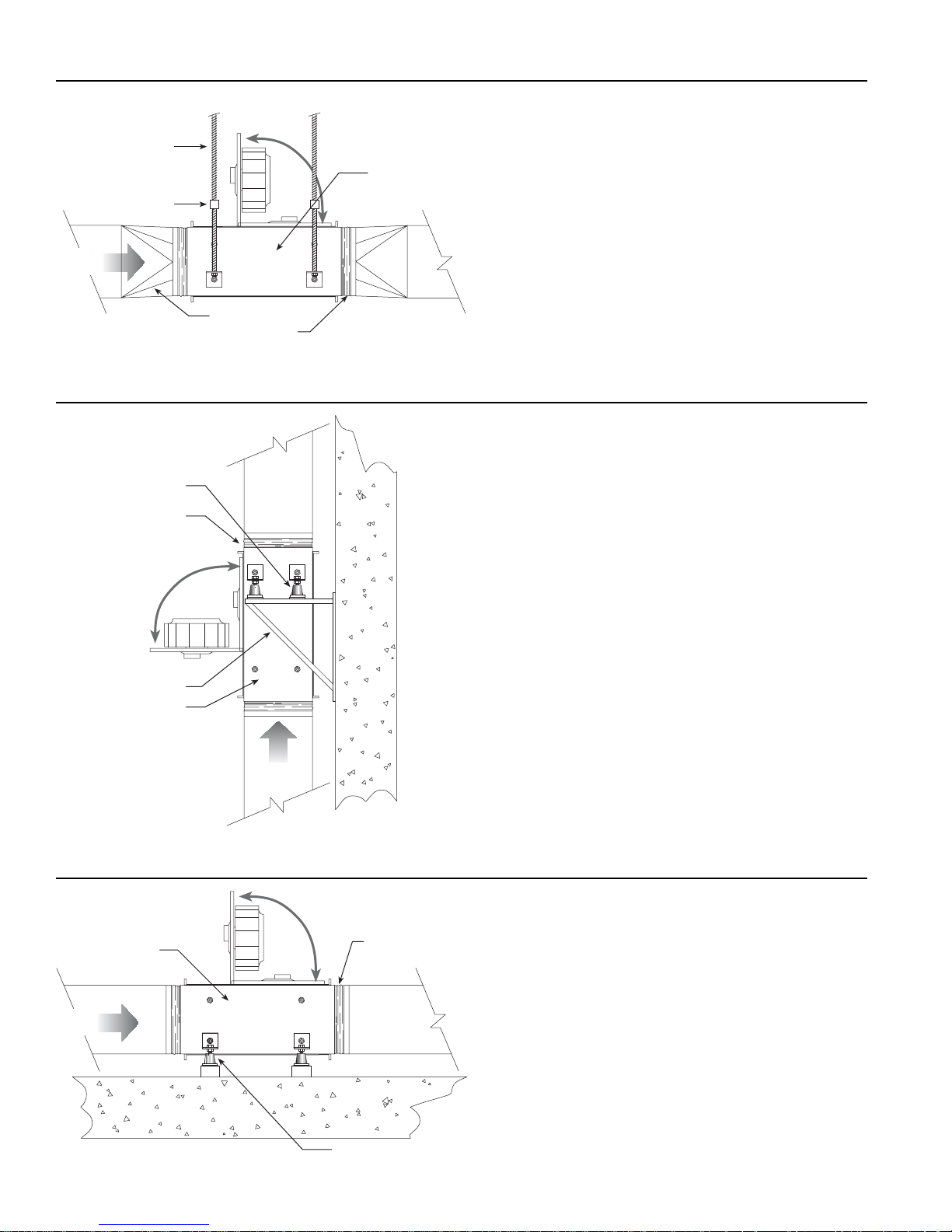
Mounting Illustration 1
Mounting Illustration 2
Mounting Illustration 3
Suspended from
structure with
threaded rod
Vibration Isolator
Fantech FRD
Series Fan
Flexible Connections
Transition as required
Support Structure
Flexible Connections
Vibration Isolator
Fantech FRD
Series Fan
Fantech FRD
Series Fan
Flexible
Connections
Vibration Isolator
2 FRD Installation Manual
Air
Flow
Air
Flow
Air
Flow
Page 3

FRD Installation Manual 3
e
e
Model A B C D E F G H J Weight
FRD 12-6 5⁷₈ 6³₄ 7⁵₈ 11⁷₈ 12³₄ 13⁵₈ 15³₄ 11 1³₄ 18
FRD 16-8 7³₄ 8³₄ 9³₈ 15³₄ 16¹₂ 17³₈ 19³₄ 15 1³₄ 23
FRD 16-8XL 7³₄ 8³₄ 9³₈ 15³₄ 16¹₂ 17³₈ 19³₄ 15 1³₄ 29
FRD 20-10 9³₄ 10⁵₈ 11³₈ 19⁵₈ 20¹₂ 21³₈ 20³₈ 18 1³₄ 41
FRD 24-14 13³₄ 14⁵₈ 15³₈ 23⁵₈ 24³⁄₈ 25¹⁄₄ 28¹⁄₂ 20 — 62
Dimensions
A
B
C
D
E
F
H
G
J
Dimensional Data
Wiring
FRD 12-6, FRD 16-8, FRD 16-8XL & FRD 20-10
FRD 24-14
Notes:
1. All leads are color coded.
2. Capacitor leads may be reversed. Fan operation will not be affected.
All dimensions in inches, Weight in pounds.
Green/Yellow ( )
Motor
Leads
Blue
Black
Brown
Capacitor
(Ground)
N (White)
L (Black)
Supply
Voltag
Green/Yellow ( )
Motor
Brown
Leads
Black
Blue
Capacitor
(Ground)
L (Black)
Supply
Voltag
N (White)
Page 4

4 FRD Installation Manual
This warranty does not apply to any FANTECH product or part which has failed as a result of faulty installation or abuse, incorrect
electrical connections or alterations made by others, or use under abnormal operating conditions or misapplication of the product
or parts. We will not approve for payment any repair not made by us or our authorized agent without prior written consent. The foregoing shall constitute our sole and exclusive warranty and our sole exclusive liability, and is in lieu of any other warranties, whether
written, oral, implied or statutory. There are no warranties which extend beyond the description on the page hereof. In no event,
whether as a result of breach of contract, or warranty or alleged negligence, defect incorrect advice or other causes, shall FANTECH be liable for special or consequential damages, including, but not limited to, loss of profits or revenue, loss of use of equipment or any other associated equipment, cost of capital, cost of substitute equipment, facilities or services, downtime costs, or
claims of customers of purchase for such damages. FANTECH neither assumes or authorizes any person to assume for it any other
liability in connection with the sale of product(s) or part(s). Some jurisdictions do not allow the exclusion or limitation of incidental or
consequential damages so the above limitations and exclusions may not apply to you.
FANTECH, INC. products are designed and manufactured to provide reliable performance, but they are not guaranteed to be 100%
free from defects. Even reliable products will experience occasional failures and this possibility should be recognized by the user.
If these products are used in a life support ventilation system where failure could result in loss or injury, the user should provide
adequate backup ventilation, supplementary natural ventilation, failure alarm system, or acknowledge willingness to accept the risk
of such loss or injury.
For factory return you must:
1) Have a return materials authorization (RMA) number. This number
may be obtained by calling FANTECH, INC. At 1-800-747-1762.
Please have bill of sale available.
2) The RMA number must be clearly displayed on the outside of the
carton, or delivery will be refused.
3) All product being returned must be shipped prepaid and be
accompanied with a copy of the bill of sale.
4) Product will be replaced/repaired and shipped back to buyer. No
credits will be issued.
During the First Thirty (30) Days:
FANTECH, INC will repair or replace any part which has a factory
defect in workmanship or material. Product may need to be returned
to the FANTECH factory, together with a copy of the bill of sale and
identified with RMA number.
During The First Three (3) Years
FANTECH, INC. will replace any product which has a factory defect in
workmanship or material. Product must be returned to the FANTECH
factory, together with bill of sale, and identified with an RMA number.
Three (3) Year Warranty
The following warranties do not apply:
Damages from shipping, either concealed or visible. Claim must be
filed with the carrier.
Damages resulting from improper wiring or installation.
Damages caused by acts of nature, or resulting from improper consumer procedures such as:
Improper maintenance,
Misuse, abuse, abnormal use, or accident, or
Incorrect electrical voltage or current.
Removal or alteration made on the FANTECH
label control number or date of manufacture.
Any other warranty, expressed, written or implied, and to any consequential or incidental damages, loss of property, revenues, or profit,
or costs of removal, installation or reinstallation, for any breach of
warranty.
Warranty validation:
The end user must keep a copy of the bill of sale to verify purchase
date.
This warranty supersedes all prior warranties
Limitation of Warranty and Liability
Warning
United States
1712 Northgate Blvd.,
Sarasota, FL. 34234
(T) 1.800.747.1762
(F) 1.800.487.9915
(T) 1.941.309.6000
(F) 1.941.309.6099
www.fantech.net
info@fantech.net
Canada
50 Kanalflakt Way,
Bouctouche, NB E4S 3M5
(T) 1.800.565.3548
(F) 1.800.747.8116
(T) 1.506.743.9500
(F) 1.506.743.9600
www.fantech.ca
info@fantech.ca
Article #: 301007
Rev Date: 081704
Distributed by
 Loading...