

Page 1
Installation and Operational Manual
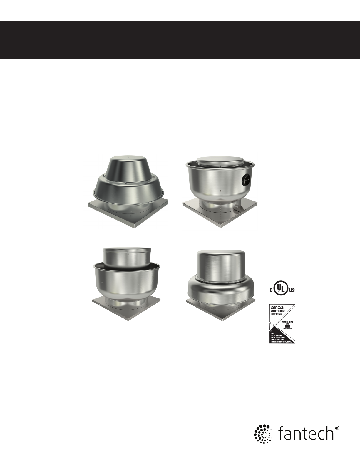
PRV Series
Power Roof Ventilators
Item #: 481806
Rev Date: 031115
United States
10048 Industrial Blvd., Lenexa, KS, 66215
Tel.: 800.747.1762 • Fax: 800.487.9915
Canada
50 Kanalflakt Way, Bouctouche, NB, E4S 3M5
Tel.: 800.565.3548 • Fax: 877.747.8116
Fantech, Inc. and Systemair
Mfg. certify that the ventilators shown herein are licensed
to bear the AMCA Seal. The
ratings shown are based
on tests and procedures
performed in accordance with
AMCA Publication 211 and
AMCA Publication 311 and
comply with the requirements
of the AMCA Certied Ratings
Program.
Page 2
2
Note Warning /
Information Technical
Important
note
Always disconnect, lock, and tag power source before installing or
servicing. Failure to disconnect power source can result in fire, shock, or
serious injury. Motor will restart without warning after thermal protector
trips. Do not touch operating motor, it may be hot enough to cause injury.
Do not place any body parts or objects in fan, motor openings, or drives
while motor is connected to power source.
Do NOT use this equipment in explosive atmospheres!
1. Read and follow all instructions and cautionary markings. Make sure
electrical power source conforms to requirements of equipment.
2. Ventilators should be assembled, installed, and serviced by a qualified
technician. Have all electrical work performed by a qualified
electrician.
3. Follow all local electrical and safety codes in the United States and
Canada - National Electrical Code (NEC), the Occupational Safety and
Health Act (OSHA), and the National Fire Protection Association
(NFPA) Bulletin 96 in the United States. Ground motor in accordance
with NEC Article 250 (grounding). Follow the Canadian Electric Code
(CEC) in Canada.
Practical tip
information
4. Motor and fan must be securely grounded (bare metal) to a suitable
electric ground, such as a grounded water pipe or ground wire
system.
In United States, to reduce the risk of injury to persons, OSHA complying
guards are required when fan is installed within 8 feet of floor, ground, or
working level.
In Canada, to reduce the risk of injury to persons, CSA complying guards
are required when fan is installed below 2.5 meters (8.2 feet) above floor
or grade level.
5. Do not kink power cable or allow it to come in contact with sharp
objects, oil, grease, hot surfaces, or chemicals.
6. Never open access door to a duct with the ventilator running.
7. Do not operate direct drive fans with speed controller less than 50%
of maximum fan speed.
Description
Power roof ventilators are designed, depending on model number, to either supply air to, or exhaust air from, commercial, institutional, and industrial
buildings. Ventilators are available in a multitude of configurations including direct-drive or belt-drive units; roof, wall, or combination roof/wall mount
and upblast or downblast discharge designs. Some units feature additional certifications required for use in kitchen ventilation systems.
Models 5DDU08 thru 5DDU18, 5DDW08 thru 5DDW18, 5BDD10 thru 5BDD49, 5BDU10 thru 5BDU36, 5ADE10 thru 5ADE24, 5ADS12 thru
5ADS24, 5DDD08 thru 5DDD18, 5FSU10 thru 5FSU20, 5ABE18 thru 5ABE36, and 5FSU10 thru 5FSU20 are UL Listed, Standard 705, & CSA
Certified when sold complete with motor and drive. Upblast Centrifugal Roof Ventilators 5BDU10 thru 5BDU36, 5DDU10 thru 5DDU18, 5DDW10
thru 5DDW18 are UL Listed, Subject 762, when sold complete with motor and drive.
Storage
If fans are stored for any length of time, they should be stored in a clean, dry location to prevent rust and corrosion. Outdoor storage is not recommended. When outdoor storage is necessary, fans should be protected from the elements as completely as possible. Cover the fan inlet and outlet
and keep motors dry and clean.
For extended storage (more than 3 months) motor shafts and bearings should be rotated monthly. If stored longer than 6 months, bearing grease in
motor and fan should be purged and replaced with compatible grease. Belts should be rechecked for proper tension. Storage records should be kept
to assure proper maintenance. The factory can advise warranty centers to provide motor and bearing service if needed.
fantech
Page 3
INSTALLATION AND MAINTENANCE INFORMATION
Receiving, Inspection & Unpacking
When the equipment is received all items should be carefully checked
against the bill of lading to be sure all crates and cartons have been
received. Before accepting delivery, carefully inspect each carton or
crate for visible shipping damage. If any damage is noticed, the carrier
should make the proper notation on the delivery receipt acknowledging
the damage. Make notations of all damage on all copies of the bill of
lading and have all copies countersigned by the delivering carrier. The
carrier should also fill out a Carrier Inspection Report. File claim for
damage with the carrier. Physical damage to the unit after acceptance is
not the responsibility of Fantech.
Unpack each carton or crate and verify that all required parts and proper
quantities of each item have been received. Refer to drawings for part
descriptions. Report shortages or missing items to your local
representative to arrange for replacement parts.
Due to availability of carriers and truck space, it is not possible to
guarantee that all items will be shipped together. Verification of
shipments must be limited to only those items on the bill of lading.
The unit nameplate must be checked to make sure the voltage agrees
with the power supply available.
3
General Installation
CAUTION: Sheet metal parts, screws, clips and similar items
inherently have sharp edges, and it is necessary that the
installer and service personnel exercise caution.
The installation of this equipment shall be in accordance with the
regulations of authorities having jurisdiction and all applicable codes.
This equipment is to be installed by an experienced installation company
and fully trained personnel.
The mechanical installation of the exhaust ventilator consists of making
final connections between the unit and building services, duct
connections.
When motors and drive packs are shipped in separate cartons from the
fan, check the carton labels to make sure the motor and drive pack you
received are the correct combination for the fan being purchased. Refer
to the fan components list included in these instructions.
Motor and Drive Pack Installation
Before mounting the motor to the fan motor/bearing support plate check
the nameplate voltage of the motor to insure that it is compatible with the
supply voltage. If the motor is a dual or tri voltage make sure the
connections inside the motor are properly wired to match the supply
voltage. Refer to the wiring schematic on the motor nameplate or inside
the junction box. Record the motor that was installed and the voltage that
the fan is wired for on the fan nameplate by checking the appropriate
boxes.
Mount the motor to the fan in a slot pattern on the motor/bearing support
plate that matches the motor frame footprint. The motor is mounted on
the same side of the motor/bearing support plate as the bearings and fan
shaft. The motor is usually mounted to the right side of the fan shaft. Use
the hardware provided which is located in the motor compartment of the
fan. Loosely snug the bolts at this time. Sizes 15, 16 and 18 have a
spacer bolt pack included. The junction box on certain motors will hit the
shaft. Use the spacers to raise the motor junction box above the shaft.
Install the adjustable sheave onto the motor shaft and the fixed sheave
onto the fan shaft. Align the sheaves as shown on page 5 of these
instructions and torque the set screws from 70 to 87 in-lbs. Install the
V-belt around the sheaves and slide the motor in the slots provided to
tension the belt (see page 4 for procedure). Once the belt is properly
tensioned and the alignment is correct tighten down the motor mounting
bolts.
Electrical Connection
1. Connect supply wiring to the disconnect switch (if supplied). Check the
wiring diagrams on the motor for connections.
2. The motor is factory set at the voltage marked on the fan nameplate.
Check the line voltage with the nameplate voltage and wiring
diagrams.
3. The main power wiring should be sized for the amperage shown on
the nameplate. Size wires in accordance with the ampacity tables in
Article 310 of the National Electrical Code. If long wires are required,
it may be necessary to increase wire size to prevent excessive
voltage drop. Wires should be sized for a max of 3% voltage drop.
CAUTION: Use copper conductors only.
CAUTION: Protect wiring from sharp edges. Leave some slack
in the line to prevent damage.
4. Disconnect switches (if supplied) are not fused. The power leads must
be protected at the point of distribution in accordance with the fan
nameplate.
5. On fans without a thermal protector integral to the motor (refer to
unit or motor nameplate to determine if protector is present) a
separate overload device is required. Refer to Sections 430-32 of the
N.E.C. for sizing.
6. All units must be electrically grounded in accordance with local codes
or, in the absence of local codes, with the latest edition of the
National Electrical Code (ANSI/NFPA 70). A ground lug is provided as
standard in the unit terminal box. Size grounding conductor in
accordance with Table 250-95 of the National Electrical Code. DO
NOT use the ground lug for connecting a neutral conductor.
7. Supply voltage to the power ventilator should not vary by more than
10% of the value indicated on the unit nameplate. Phase unbalance
must not exceed 2%.
WARNING: Failure of motor due to operation on improper line
voltage or with excessive phase unbalance constitutes product
abuse and may cause severe damage to the unit’s electrical
components.
fantech
Page 4
4
Roof Fan Installation
Downblast Fans:
1.Position the fan with its wiring conduit in line
with the wiring coming up through the roof
curb and damper (if present). If the fan has
an external disconnect switch, position the
fan with the junction box towards the power
supply.
Upblast Fans:
1. Position the fan with its wiring conduit,
coming through the outer fan housing or its
external disconnect, towards the power
supply.
2. Run wires through the conduit to the switch.
Leave some slack in the wire in the motor
BEFORE START-UP: Disconnect power to this unit
before servicing the unit.
1. Check to verify that the wheel is free to
rotate.
2. For optimum fan performance make sure
that the wheel to inlet venturi overlap
(0.25”) is maintained.
3. Verify that supply voltage on the line side
of disconnect agrees with voltage on fan
nameplate and is within the 10% utilization
voltage.
4. Apply power to unit and check rotation of
wheel with the directional arrow on the unit.
WARNING: Rotation is critical. If
allowed to operate in the wrong
direction, the motor will overload and
bum out. Wheel rotation is clockwise
(CW) when viewed from the top
or drive side of the fan. Especially
check three-phase units for rotation.
For three-phase, rotation can be
changed by interchanging any two of
the three line leads. If unit is checked
on temporary wiring, it should
be rechecked when permanently
installed. Motor bum-out or tripped
overload protection devices are
usually the result of wrong rotation.
5. Electrical Input Check: Perform check of
fan ampere draw and verify that motor
nameplate amps are not exceeded. Take into
account the service factor range if the motor
is nameplated above a 1.0 service factor.
6. Fan RPM should be checked and veried with
a tachometer.
fantech
compartment so the motor and wheel
assembly can be lifted for inspection and
cleaning.
3. Bolt the fan base to the roof curb through
the holes provided on the base using eight
(8) lag bolts.
4. Make connection to the disconnect switch
per above electrical instructions.
5. Restaurant fan installation must be in
compliance with local codes and the
National Fire Protection Association’s NFPA-
96.
NOTE: The fan should not need
balancing, as it was balanced at
the factory to be within stringent
vibration levels before shipment.
However, there are several things
that may cause vibration, such as
rough handling in shipment and
installation, weak foundations and
alignments.
V-Belts
V-belts on these belt driven fans are oil, heat,
and static resistant type and oversized for
continuous duty. With proper installation and
maintenance, years of operating efciency can
be added to the lifespan of the V-belt drive.
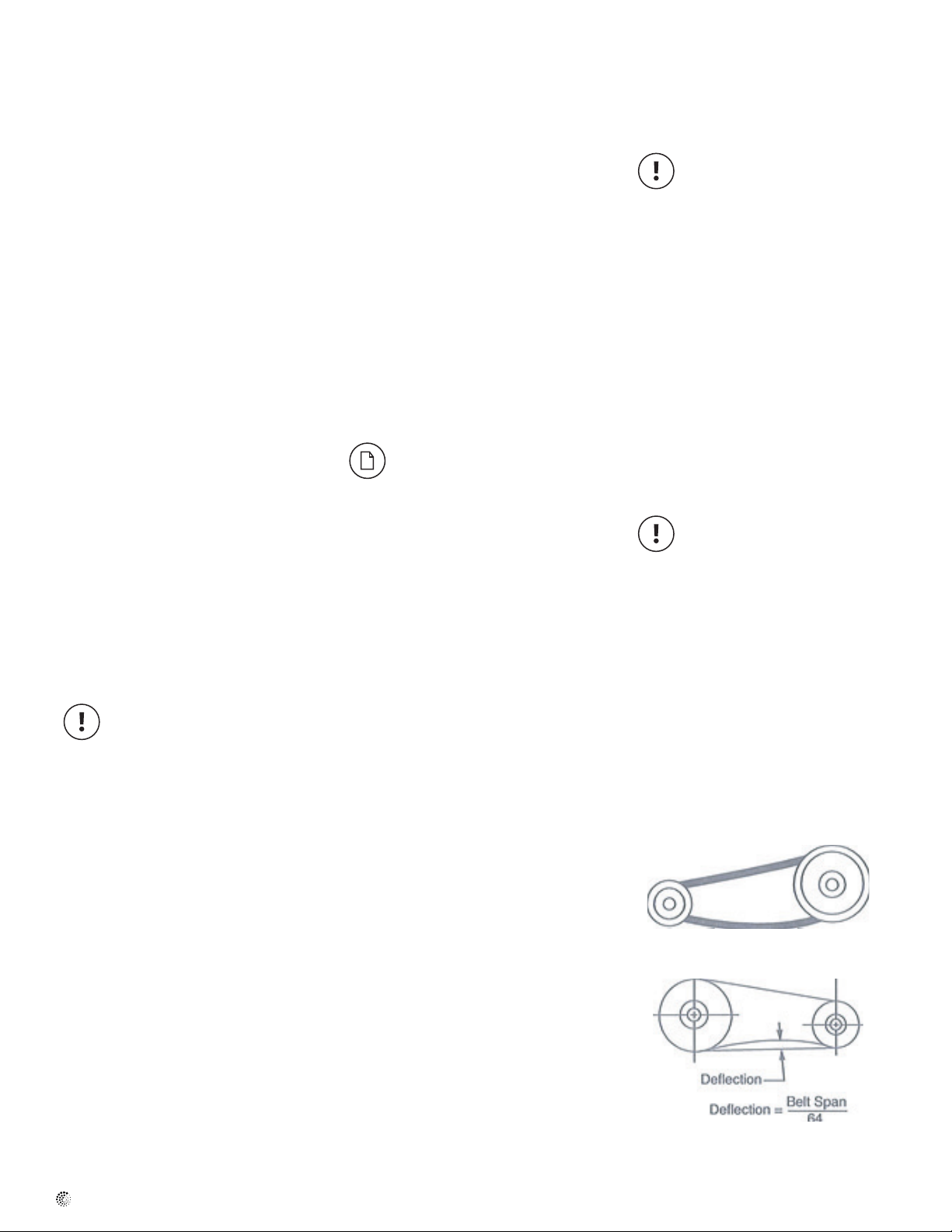
The condition of V-belts and the amount of belt
tension should be checked prior to start-up
(see Figure1). When it becomes necessary
to adjust belt tension, do not over-tension as
bearing damage will occur. Recommended
belt tension should permit 1/64 deection per
inch of span of the belt at the center of the
belt span. To nd this point, measure halfway
between the pulley centerlines as shown in
Figure 2. Extreme care must be exercised when
adjusting V-belts as not to misalign the pulleys.
Any misalignment will cause a sharp reduction
in belt life and will also produce squeaky,
annoying noises (see Figure 3). On units
equipped with 2 groove pulleys, adjustments
must be made so that there is equal tension on
all belts (see Figure 4).
1. When tensioning loosen the motor mounting
bolts and slide motor until proper tension is
obtained.
2. Always loosen tension adjustment enough
to place belts on sheaves without running
Check, Test & Start Procedure
WARNING: Electric shock hazard.
Could cause severe injury or death.
Failure to bond the frame of this
equipment to the building electrical
ground by use of the grounding
terminal provided or other acceptable
means may result in electrical shock.
Disconnect electric power before
servicing equipment. Service to be
performed only by qualified
personnel.
belts over the edge of either sheave. A new
belt may be seriously damaged internally by
careless handling (see Figure 5).
WARNING: When removing or
installing belts, never force belts over
pulleys without loosening motor rst
to relieve belt tension. The fan has
been checked for mechanical noises
at the factory prior to shipment. If
mechanical noise should develop, then
some suggestions are offered here as
a guide toward remedying the cause.
1. Check rotating members for adequate
clearance.
2. Check proper belt tension and pulley
alignment.
3. Check installation and anchoring.
4. Check fan bearings.
Figure 1. Eliminate Slack
Figure 2. Belt Deection
Slack belts wear excessively, cause slippage
and deliver less power. For the longest belt life,
always provide proper tension.
Page 5

5
Figure 3. Alignment
INCORRECT
CORRECT
Mount belts straight. Shafts must be parallel
And sheaves in alignment to prevent belt wear.
Figure 4. Two Groove Sheaves
Two groove adjustable sheaves must be opened
the same number of turns on both sides.
Figure 5. Belts
Do not force belt. Forcing the belt will break the
cords and cause belt
Maintenance
Installation and maintenance are to be
performed only by qualied personnel who are
familiar with local codes and regulations and
experienced with this type of equipment.
CAUTION: Sharp edges and screws
are a potential injury hazard. Avoid
them.
WARNING: Hazardous moving parts.
Unit may contain protected fan motor
which may start automatically and
cause injury. Allow time for reset.
Disconnect power before servicing.
Preventive maintenance is the best way to
avoid unnecessary expense and inconvenience.
Start-up and routine maintenance should cover
the following items:
a. Tighten all setscrews, bolts and wire
connections.
b. Check belt tension and sheaves for wear.
c. Lubricate fan bearings (see Tables 1 and 2).
d. Cleaning of unit, wheel and damper (if
present).
All motors containing ball bearings
are permanently lubricated from the
factory. No additional maintenance is
required.
1. Before performing any maintenance on the
fan, be sure power is turned off and locked
in the OFF position at the service entrance.
2. Ventilators should be carefully checked at
least once a year. For critical or rugged
applications, a routine check every two or
three months is suggested.
3. All motors supplied with Fantech ventilators
carry a one-year limited warranty from date
of shipment. For repairs within the warranty
period, the motor must be taken to the
motor manufacturer’s authorized service
dealer. Contact your representative for
additional warranty details.
4. A periodic motor check should consist of
spinning the motor shaft with the power
off to be sure the motor turns freely and
the bearings run smoothly. The belt on belt
driven units should be removed from the
motor sheave.
5. When removing or installing a belt, do not
force the belt over the sheave. Loosen the
motor mount so that the belt can be easily
slipped over the sheave.
6. The belt on belt driven units should be
removed and carefully checked for glazing,
cracks, ply separation or irregular wear.
A small irregularity in the contact surface
of the belt will result in noisy operation. If
any of these defects are apparent, the belt
should be replaced. Check the sheaves also
for chipping, dents or rough surfaces which
could damage the belt.
7. The correct belt tension is important. Too
tight of a belt will result in excess bearing
pressure on the motor bearings and shaft
pillow blocks and may also overload the
motor. Too loose of a belt will result in
slippage which will quickly “burn” out belts.
A belt should feel “live” when thumped,
approximately W belt deection (3 to 5 lb.)
when subject to nger pressure at midpoint
between sheaves.
8. The belt alignment should also be checked to
be sure the belt is running perpendicularly to
the rotating shafts. Fan and motor
shafts must be parallel. Improper alignment
will result in excessive belt wear.
9. Check sheave setscrews to ensure
tightness. Proper keys must be in keyways.
10. Do not readjust fan RPM. If sheaves are
replaced, use only sheaves of identical size
and type.
11. If unit is to be left idle for an extended
period, it is recommended that belts be
removed and stored in a cool, dry place to
avoid premature belt failure.
12. The standard pillow block bearings on belt
driven ventilators are factory lubricated and
are provided with external grease ttings.
Lubrication annually is recommended, or
more frequently if needed (see Table 1).
It is recommended to add fresh grease at
start-up, but do not over-grease. Use only
1 or 2 shots of a recommended lubricant
with a hand gun in most cases (see Table 2).
Maximum hand gun rating 40 P.S.I. Rotate
bearings during lubrication where good
safety practice permits.
CAUTION: Greases of different soap
bases (lithium, sodium, etc.) may not
be compatible when mixed. Prevent
such intermixing by completely
purging the bearing of old greases.
The most frequent causes of bearing
failure are not greasing often enough,
using an excessive quantity of grease,
or using incompatible greases.
Excessive vibration, especially if
the bearing is not rotating, will also
cause bearings to fail. Bearings must
also be protected from water and
moisture to avoid internal corrosion.
13. During the rst few months of operation it
is recommended that the bearing setscrews
be checked periodically to ensure that they
are tight.
14. The rotating wheel requires particular
attention since materials in the air being
handled can build up on the blades to
cause destructive vibration or weaken the
structure of the wheel by corroding and/or
eroding the blade metal. Regular inspection
and corrective action at intervals determined
by the severity of each application are
essential to good service life and safety.
fantech
Page 6

6
Intervals Type of service
12 to 8 Infrequent operation or light duty in clean atmosphere
6 to 12 8 to 16 hrs./day in clean, relatively dry atmosphere
3 to 6 12 to 24 hrs./day, heavy duty, or if moisture is present
1 to 3 Heavy duty in dirty, dusty locations; high ambient tem-
peratures; moisture laden atmosphere; vibration
Table 1. Suggested fan bearing greasing intervals
Fan Troubleshooting Chart
Problem Possible causes
Fan does not operate 1. Wrong voltage
2. Electricity turned off or not wired properly
3. Tripped overload protector
4. Blown fuses
5. Loose pulleys
6. Broken belts
Too little air 1. Wheel rotating in wrong direction.
2. Fan speed lower than design.
3. System is more restrictive (more static pressure) than expected.
4. Restricted fan inlet or outlet.
5. Inlet or outlet screens clogged.
6. Filters (if applicable) are dirty or clogged.
Too much air 1. Fan speed higher than design.
2. System is less restrictive (less static pressure) than expected.
Maunfacturer Grease (NLGI #2)
Shell Alvania RL2
Exxon/Mobil Ronex MP
Table 2. Grease manufacturers
Excessive horsepower 1. Wheel rotating in wrong direction.
2. Wheel rubbing on inlet venturi.
3. Fan speed higher than design.
4. Worn fan bearings.
Excessive noise 1. Wheel or sheaves loose.
2. Bearing or drive misalignment.
3. Accumulation of material on wheel.
4. Worn or corroded wheel.
5. Wheel out of balance.
6. Bent shaft
7. Bearings need lubrication
8. Loose bearing bolts.
9. Loose or worn bearings.
10. Mismatched belts.
11. Belts too loose or too tight.
12. Belts oily or dirty.
13. Belts worn.
14. Loose fan mounting bolts.
15. Rattle of loose components in high velocity airstream.
16. Electrical noise.
17. Noise from high velocity air system.
18. Vibrating parts not isolated from building.
19. Vibrating ductwork.
Excessive vibration 1. Wheel or sheaves loose on shaft.
2. Wheel out of balance.
3. Excessive buildup of dirt/dust on wheel.
4. Belts too loose or too tight.
5. Mismatched belts.
6. Bent shaft.
7. Bearing or drive misalignment
8. Loose or worn bearings
9. Loose bolts
10. Weak mounting base for fan.
11. Curb not at and level.
It is recommended that the users and installers of this shipment familiarize themselves with AMCA Publication #201, "Fans and Systems" and publication #202, "Troubleshooting" which are published by the Air Movement and Control Association (AMCA), 30 West University Drive, Arlington Heights,
Illinois 60004. www.amca.org
fantech
Page 7

Dimensions
7
Belt-Drive Downblast Roof Ventilators
Model Wheel
Diameter
5BDD 10 10 1/
5BDD 12 12 1/
5BDD 13 13 1/
5BDD 15 15
5BDD 16 16 1/
5BDD 18 18 1/
5BDD 20 20
5BDD 24 21 1/
5BDD 30 30 1 3/
5BDD 36 36 1/
Dimensional information is in inches.
Shaft Size Dimensions Shipping
5
5
5
7
7
7
7
7
1 3/
/
8
/
8
/
8
/
8
/
8
/
8
/
8
/
8
16
16
2
4
2
2
4
2
2
A B C D E
19 25 3/
22 28 23 3/
22 29 3/
26 31 11/
26 33 11/
30 36 29 5/
30 36 1/
34 44 1/
42 51 7/
46 60 41 5/
4
4
16
16
4
4
16
22 7/
24 5/
27 3/
27 3/
30 1/
33 6 11/
37 1/
8
8
8
8
4
8
4
2
8
3 1 1/
3 1 1/
3 1/
3 3/
4 3/
4 3/
5 1/
8 13/
10 1/
4
4
16
4
4
16
32
2
1 1/
1 1/
1 1/
1 1/
1 1/
1 1/
1 1/
1 1/
B
C
D
A
Weight
2
2
2
2
2
2
2
2
2
2
90 14 1/2 SQ. 17 1/
100 17 1/2 SQ. 20 1/
110 17 1/2 SQ. 20 1/
120 21 1/2 SQ. 24 1/
130 21 1/2 SQ. 24 1/
164 25 1/2 SQ. 28 1/
185 25 1/2 SQ. 28 1/
212 29 1/2 SQ. 32 1/
310 37 1/2 SQ. 40 1/
380 43 1/2 SQ 44 1/
E
Recommended Roof
Opening
Curb Size
2
2
2
2
2
2
2
2
2
2
Direct-Drive Downblast Roof Ventilators
Model Wheel
5DDD 085A 8 n/a 19 18 7/
5DDD 106A & 10AA 10 1/
5DDD 12CA 12 1/
5DDD 13DB 13 1/
5DDD 15CA 15 n/a 26 27 7/
5DDD 16DB 16 1/
5DDD 18EB 18 1/
Dimensional information is in inches.
Diameter
2
4
2
2
4
Shaft Size Dimensions Shipping
A B C D
n/a 19 22 3/
n/a 22 24 1/
n/a 22 25 5/
n/a 26 29 3/
n/a 30 31 5/
B
C
D
A
Weight
8
8
4
8
8
4
8
13 1/
16 1/
17 1/
18 1/
18 1/
20 1/
21 3/
4
2
8
8
2
4
8
3 1/
2
3 3/
8
4 101 17 1/2 SQ. 20 1/
4 3/
8
4 3/
8
4 3/
4
5 5/
8
26 14 1/2 SQ. 17 1/
94 14 1/2 SQ. 17 1/
115 17 1/2 SQ. 20 1/
132 21 1/2 SQ. 24 1/
142 21 1/2 SQ. 24 1/
157 25 1/2 SQ. 28 1/
1.50
Recommended Roof
Opening
Curb Size
2
2
2
2
2
2
2
fantech
Page 8

8
Dimensions
Belt-Drive Upblast Roof Ventilators
Model Wheel
Diameter
5BDD 10 10 1/
5BDD 12 12 1/
5BDD 13 13 1/
5BDD 15 15
5BDD 16 16 1/
5BDD 18 18 1/
5BDD 20 20
5BDD 24 21 1/
5BDD 30 30 1 3/
5BDD 36 36 1/
Dimensional information is in inches.
Shaft Size Dimensions Shipping
5
5
5
7
7
7
7
7
1 3/
/
8
/
8
/
8
/
8
/
8
/
8
/
8
/
8
2
4
2
2
4
2
2
B
C
D
E
A
A B C D E
19 23 7/
22 26 1/
22 27 7/
26 29 7/
26 31 3/
30 34 31 1/
30 36 1/
34 42 3/
16
16
42 49 1/
46 58 1/
25 3/
8
25 13/
2
26 1/
8
27 3/
8
28 3/
4
32 5/
2
35 3/
8
41 1/
2
45 1/
16
16 7/
16
17 7/
16
18 1/
2
19 3/
8
20 3/
8
21 1/
2
22 1/
8
24 5/
8
27 5/
8
31 1/
8
1 1/
8
8
2
8
16
8
8
8
8
4
1 1/
1 1/
1 1/
1 1/
1 1/
1 1/
1 1/
1 1/
1 1/
2
2
2
2
2
2
2
2
2
2
Weight
90 14 1/2 SQ. 17 1/
100 17 1/2 SQ. 20 1/
105 17 1/2 SQ. 20 1/
120 21 1/2 SQ. 24 1/
125 21 1/2 SQ. 24 1/
171 25 1/2 SQ. 28 1/
173 25 1/2 SQ. 28 1/
205 29 1/2 SQ. 32 1/
305 37 1/2 SQ. 40 1/
385 43 1/2 SQ 44 1/
Recommended Roof
Opening
Curb Size
2
2
2
2
2
2
2
2
2
2
Direct-Drive Upblast Roof Ventilators
Model Wheel
5DDU 085AY 8 n/a 19 20 1/
5DDU 106A & 10AA 10 1/
5DDU 12CA 12 1/
5DDU 13DB 13 1/
5DDU 15CA 15 n/a 26 29 7/
5DDU 16DB 16 1/
5DDU 18EB 18 1/
Dimensional information is in inches.
Diameter
2
4
2
2
4
Shaft Size Dimensions Shipping
A B C D
n/a 19 23 7/
n/a 22 26 1/
n/a 22 27 7/
n/a 26 31 3/
n/a 30 34 24 21 1/
B
C
D
1.50
A
Weight
2
8
8
8
8
4
12 1/
8
18 7/
8
19 5/
8
20 3/
4
22 19 3/
22 3/
4
10 23 14 1/2 SQ. 17 1/
16 7/
17 3/
18 1/
20 1/
8
4
2
8
8
8
88 14 1/2 SQ. 17 1/
109 17 1/2 SQ. 20 1/
117 17 1/2 SQ. 20 1/
130 21 1/2 SQ. 24 1/
144 21 1/2 SQ. 24 1/
159 25 1/2 SQ. 28 1/
Recommended Roof
Opening
Curb Size
2
2
2
2
2
2
2
fantech
Page 9

Shell Belt Drive Fan Components List
9
Shell Roof curb
Model
Art. # Weight,
HP
Drive Pack Motor Drive Pack Motor
Max
lbs
Opening
Model Art. # Weight,
lbs
Art. # DP ID Art. # Motor ID Art. # DP ID Item # Motor
1 Phase 3 Phase
ID
Dimensions
5BDU10 49800 90 19” x 19” 5ACC17FS /FT /VC 47206 / 47207 / 47208 24 / 29 / 38 1/4 48992 DP-10"-BB 49907 MOT BB
5BDU12 49801 100 22” x 22” 5ACC20FS /FT /VC 47212 / 47213 / 47214 28 / 33 / 38 1/4 48993 DP-12"-BB 49907 MOT BB
1/3 48994 DP-12"-CB 49909 MOT CB
5BDU13 49802 105 22” x 22” 5ACC20FS /FT /VC 47212 / 47213 / 47214 28 / 33 / 38 1/4 48995 DP-13"-BB 49907 MOT BB
1/3 48996 DP-13"-CB 49909 MOT CB
1/2 48997 DP-13"-DB 49910 MOT DB 49000 DP-13"-DX 49911 MOT DX
5BDU15 49803 120 26” x 26” 5ACC24FS /FT /VC 47217 / 47941 / 47219 33 / 38 / 47 1/4 49001 DP-15"-BB 49907 MOT BB
1/3 49002 DP-15"-CB 49909 MOT CB
1/2 49003 DP-15"-DB 49910 MOT DB 49004 DP-15"-DX 49911 MOT DX
3/4 49005 DP-15"-EB/EX 49912 MOT EB 49005 DP-15"-EB/EX 49913 MOT EX
1 49007 DP-15"-FB/FX 49914 MOT FB 49007 DP-15"-FB/FX 49915 MOT FX
5BDU16 49804 125 26” x 26” 5ACC24FS /FT /VC 47217 / 47941 / 47219 33 / 38 / 47 1/3 49010 DP-16"-CB 49909 MOT CB
1/2 49011 DP-16"-DB 49910 MOT DB 49012 DP-16"-DX 49911 MOT DX
3/4 49013 DP-16"-EB/EX 49912 MOT EB 49013 DP-16"-EB/EX 49913 MOT EX
1 49015 DP-16"-FB/FX 49914 MOT FB 49015 DP-16"-FB/FX 49915 MOT FX
5BDU18 49805 171 30” x 30” 5ACC28FS /FT /VC 47221 / 47222 / 47223 40 / 48 / 54 1/3 49017 DP-18"-CB 49909 MOT CB
1/2 49018 DP-18"-DB 49910 MOT DB 49019 DP-18"-DX 49911 MOT DX
3/4 49020 DP-18"-EB/EX 49912 MOT EB 49020 DP-18"-EB/EX 49913 MOT EX
1 49022 DP-18"-FB/FX 49914 MOT FB 49022 DP-18"-FB/FX 49915 MOT FX
1-1/2 49024 DP-18"-GB 49916 MOT GB 49024 DP-18"-GB 49917 MOT GX
2 49026 DP-18"-HX 49918 MOT HX
5BDU20 49806 173 30” x 30” 5ACC28FS /FT /VC 47221 / 47222 / 47223 40 / 48 / 54 1/3 49027 DP-20"-CB 49909 MOT CB
1/2 49028 DP-20"-DB 49910 MOT DB 49029 DP-20"-DX 49911 MOT DX
3/4 49031 DP-20"-EB/EX 49912 MOT EB 49031 DP-20"-EB/EX 49913 MOT EX
1 49032 DP-20"-FB/FX 49914 MOT FB 49032 DP-20"-FB/FX 49915 MOT FX
1-1/2 49036 DP-20"-GB/GX 49916 MOT GB 49036 DP-20"-GB/GX 49917 MOT GX
2 49038 DP-20"-HX 49918 MOT HX
5DBU24 49807 205 34” x 34” 5ACC32FS /FT /VC 47226 / 47227 / 47228 46 / 53 / 52 1/3 49039 DP-24"-CB 49909 MOT CB
1/2 49040 DP-24"-DB 49910 MOT DB 49041 DP-24"-DX 49911 MOT DX
3/4 49042 DP-24"-EB/EX 49912 MOT EB 49042 DP-24"-EB/EX 49913 MOT EX
1 49044 DP-24"-FB/FX 49914 MOT FB 49044 DP-24"-FB/FX 49915 MOT FX
1-1/2 49046 DP-24"-GB/GX 49916 MOT GB 49046 DP-24"-GB/GX 49917 MOT GX
2 49051 DP-24"-HX 49918 MOT HX
5BDU30 49808 305 42” x 42” 5ACC40FS /FT /VC 47233 / 47901 / 47234 57 / 68 / 63 1/2 49466 DP-30"-DB 49910 MOT DB 49052 DP-30"-DX 49911 MOT DX
3/4 49053 DP-30"-EB/EX 49912 MOT EB 49053 DP-30"-EB/EX 49913 MOT EX
1 49055 DP-30"-FB/FX 49914 MOT FB 49055 DP-30"-FB/FX 49915 MOT FX
1-1/2 49057 DP-30"-GB/GX 49916 MOT GB 49057 DP-30"-GB/GX 49917 MOT GX
2 49060 DP-30"-HX 49918 MOT HX
3 49061 DP-30"-JX 49919 MOT JX
5 49062 DP-30"-KX 49920 MOT KX
5BDU36 49809 385 46” x 46” 5ACC44FS /FT /VC 47237 / 47238 / 47665 68 / 73 / 92 3/4 49063 DP-36"-EB/EX 49912 MOT EB 49063 DP-36"-EB/EX 49913 MOT EX
1 49065 DP-36"-FB/FX 49914 MOT FB 49065 DP-36"-FB/FX 49915 MOT FX
1-1/2 49067 DP-36"GB/GX 49916 MOT GB 49067 DP-36"GB/GX 49917 MOT GX
2 49069 DP-36"-HX 49918 MOT HX
3 49070 DP-36"-JX 49919 MOT JX
5 49072 DP-36"-KX 49920 MOT KX
fantech
Page 10

10
Shell Belt Drive Fan Components List (cont.)
Shell Roof curb
Model
Art. # Weight,
HP
Drive Pack Motor Drive Pack Motor
Max
lbs
Opening
Model Art. # Weight,
lbs
Art. # DP ID Art. # Motor ID Art. # DP ID Item # Motor
1 Phase 3 Phase
ID
Dimensions
5BDD10 49810 90 19” x 19” 5ACC17FS /FT /VC 47206 / 47207 / 47208 24 / 29 / 38 1/4 48992 DP-10"-BB 49907 MOT BB
5BDD12 49811 100 22” x 22” 5ACC20FS /FT /VC 47212 / 47213 / 47214 28 / 33 / 38 1/4 48993 DP-12"-BB 49907 MOT BB
1/3 48994 DP-12"-CB 49909 MOT CB
5BDD13 49812 110 22” x 22” 5ACC20FS /FT /VC 47212 / 47213 / 47214 28 / 33 / 38 1/4 48995 DP-13"-BB 49907 MOT BB
1/3 48996 DP-13"-CB 49909 MOT CB
1/2 48997 DP-13"-DB 49910 MOT DB 49000 DP-13"-DX 49911 MOT DX
5BDD15 49813 120 26” x 26” 5ACC24FS /FT /VC 47217 / 47941 / 47219 33 / 38 / 47 1/4 49001 DP-15"-BB 49907 MOT BB
1/3 49002 DP-15"-CB 49909 MOT CB
1/2 49003 DP-15"-DB 49910 MOT DB 49004 DP-15"-DX 49911 MOT DX
3/4 49005 DP-15"-EB/EX 49912 MOT EB 49005 DP-15"-EB/EX 49913 MOT EX
1 49007 DP-15"-FB/FX 49914 MOT FB 49007 DP-15"-FB/FX 49915 MOT FX
5BDD16 49814 130 26” x 26” 5ACC24FS /FT /VC 47217 / 47941 / 47219 33 / 38 / 47 1/3 49010 DP-16"-CB 49909 MOT CB
1/2 49011 DP-16"-DB 49910 MOT DB 49012 DP-16"-DX 49911 MOT DX
3/4 49013 DP-16"-EB/EX 49912 MOT EB 49013 DP-16"-EB/EX 49913 MOT EX
1 49015 DP-16"-FB/FX 49914 MOT FB 49015 DP-16"-FB/FX 49915 MOT FX
5BDD18 49815 164 30” x 30” 5ACC28FS /FT /VC 47221 / 47222 / 47223 40 / 48 / 54 1/3 49017 DP-18"-CB 49909 MOT CB
1/2 49018 DP-18"-DB 49910 MOT DB 49019 DP-18"-DX 49911 MOT DX
3/4 49020 DP-18"-EB/EX 49912 MOT EB 49020 DP-18"-EB/EX 49913 MOT EX
1 49022 DP-18"-FB/FX 49914 MOT FB 49022 DP-18"-FB/FX 49915 MOT FX
1-1/2 49024 DP-18"-GB 49916 MOT GB 49024 DP-18"-GB 49917 MOT GX
2 49026 DP-18"-HX 49918 MOT HX
5BDD20 49816 185 30” x 30” 5ACC28FS /FT /VC 47221 / 47222 / 47223 40 / 48 / 54 1/3 49027 DP-20"-CB 49909 MOT CB
1/2 49028 DP-20"-DB 49910 MOT DB 49029 DP-20"-DX 49911 MOT DX
3/4 49031 DP-20"-EB/EX 49912 MOT EB 49031 DP-20"-EB/EX 49913 MOT EX
1 49032 DP-20"-FB/FX 49914 MOT FB 49032 DP-20"-FB/FX 49915 MOT FX
1-1/2 49036 DP-20"-GB/GX 49916 MOT GB 49036 DP-20"-GB/GX 49917 MOT GX
2 49038 DP-20"-HX 49918 MOT HX
5BDD24 49817 212 34” x 34” 5ACC32FS /FT /VC 47226 / 47227 / 47228 46 / 53 / 52 1/3 49039 DP-24"-CB 49909 MOT CB
1/2 49040 DP-24"-DB 49910 MOT DB 49041 DP-24"-DX 49911 MOT DX
3/4 49042 DP-24"-EB/EX 49912 MOT EB 49042 DP-24"-EB/EX 49913 MOT EX
1 49044 DP-24"-FB/FX 49914 MOT FB 49044 DP-24"-FB/FX 49915 MOT FX
1-1/2 49046 DP-24"-GB/GX 49916 MOT GB 49046 DP-24"-GB/GX 49917 MOT GX
2 49051 DP-24"-HX 49918 MOT HX
5BDD30 49818 310 42” x 42” 5ACC40FS /FT /VC 47233 / 47901 / 47234 57 / 68 / 63 1/2 49466 DP-30"-DB 49910 MOT DB 49052 DP-30"-DX 49911 MOT DX
3/4 49053 DP-30"-EB/EX 49912 MOT EB 49053 DP-30"-EB/EX 49913 MOT EX
1 49055 DP-30"-FB/FX 49914 MOT FB 49055 DP-30"-FB/FX 49915 MOT FX
1-1/2 49057 DP-30"-GB/GX 49916 MOT GB 49057 DP-30"-GB/GX 49917 MOT GX
2 49060 DP-30"-HX 49918 MOT HX
3 49061 DP-30"-JX 49919 MOT JX
5 49062 DP-30"-KX 49920 MOT KX
5BDU36 49809 385 46” x 46” 5ACC44FS /FT /VC 47237 / 47238 / 47665 68 / 73 / 92 3/4 49063 DP-36"-EB/EX 49912 MOT EB 49063 DP-36"-EB/EX 49913 MOT EX
1 49065 DP-36"-FB/FX 49914 MOT FB 49065 DP-36"-FB/FX 49915 MOT FX
1-1/2 49067 DP-36"GB/GX 49916 MOT GB 49067 DP-36"GB/GX 49917 MOT GX
2 49069 DP-36"-HX 49918 MOT HX
3 49070 DP-36"-JX 49919 MOT JX
5 49072 DP-36"-KX 49920 MOT KX
fantech
Page 11

Warranty
11
Fantech, Inc. warrants to the original purchaser that our products will be
free from defects in material and workmanship for a period of one (1)
year from the date of shipment. THIS IS OUR SOLE AND EXCLUSlVE
PRODUCT WARRANTY AND IS IN LIEU OF AND EXCLUDES ALL OTHER
WARRANTIES, EXPRESS OR IMPLIED, ARISING BY OPERATION OF LAW
OR OTHERWISE, INCLUDING WITHOUT LIMITATION, MERCHANTABILITY
AND FITNESS FOR A PARTICULAR PURPOSE WHETHER OR NOT THE
PURPOSE OR USE HAS BEEN DISCLOSED TO US IN SPECIFICATIONS,
DRAWINGS DR OTHERWISE, AND WHETHER OR NOT OUR PRODUCTS
ARE SPECIFICALLY DESIGNED AND/OR MANUFACTURED BY US FOR
PURCHASER’S USE OR PURPOSE.
This warranty does not cover any losses or damages due to misuse,
accident, abuse, neglect, normal wear and tear, negligence [other than
ours), unauthorized alteration, use beyond rated capacity, or improper
installation, maintenance or application. This warranty shall be null and
void to the extent that purchaser supplied incorrect information to us
about the necessary product specifications or the environment in which
the products were to be used, and our selection or design of the
products for the purchaser was based in part on such information.
Limitation of Warranty and Liability
THE SOLE AND EXCLUSIVE REMEDY FOR BREACH OF ANY WARRANTY
HEREUNDER SHALL BE LIMITED TO REPAIR, CORRECTION OR
REPLACEMENT, OR REFUND OF THE PURCHASE PRICE UNDER THE
PRECEDING PARAGRAPH ENTITLED “LIMITED WARRANTY”. FANTECH
VENTILATION PRODUCTS SHALL NOT BE LIABLE FOR DAMAGES
CAUSED BY DELAY IN PERFORMANCE AND IN NO EVENT,
REGARDLESS OF THE FORM OF THE CLAIM OR CAUSE OF ACTION,
SHALL OUR LIABILITY TO PURCHASER AND/OR ITS CUSTOMERS
EXCEED THE PRICE PAID BY PURCHASER FOR THE SPECIFIC PRODUCT
PROVIDED BY US THAT GAUE RISE TO THE CLAIM OR CAUSE OF
If within thirty (30) days after purchaser’s discovery of any warranty
defects within the warranty period, purchaser notifies us thereof in
writing, we shall, at our option, repair, correct or replace F.O.B. point of
manufacture, or refund the purchase price for, the products that we have
found to be defective. Failure by purchaser to give such written notice
within the 30-day time period shall be deemed an absolute and
unconditional waiver of purchaser’s claim for such defects. Products
repaired or replaced shall be covered by this warranty for the remainder
of the original warranty period or ninety (90) days from the date of
shipment, whichever is longer.
Warranty claims should be sent to Fantech, Inc.,
Attn: Quality Department, 10048 Industrial Blvd., Lenexa, KS 66215.
Included in the claim should be Order Number, Model Numbers, Serial
Numbers and a detailed description of the issues.
Purchaser assumes all other responsibility for any loss, damage or injury
to persons or property arising out of the use of our products, either
alone or in combination with other products or components.
ACTION. PURCHASER AGREES THAT IN NO EVENT SHALL OUR
LIABILITY TO PURCHASER AND/OR ITS CUSTOMERS EXTEND TO
INCLUDE INCIDENTAL, CONSEQUENTIAL OR PUNITIVE DAMAGES. The
term “consequential damages” shall include, but not be limited to,
loss of anticipated profits, business interruption, loss of use or revenue,
cost of capital, or loss or damage to property or equipment.
It is expressly understood that any technical advice furnished by us with
respect to the use of our products is given without charge, and we
assume no obligation or liability for the advice given, or results obtained,
all such advice being given and accepted.
Warning
Fantech products are designed and manufactured to provide reliable
performance, but they are not guaranteed to be 100% free from
defects. Even reliable products will experience occasional failures and
this possibility should be recognized by the user. If these products are
used in a life support ventilation system where failure could result in loss
or injury, the user should provide adequate backup ventilation,
supplementary natural ventilation, failure alarm system, or acknowledge
willingness to accept the risk of such loss or injury.
For Customer/Technical Support call (800) 747-1762
fantech
Page 12

Fantech reserves the right to make technical changes.
For updated documentation please refer to www.fantech.net
Fantech®
 Loading...