

Fantech 2SHE1021, 2SHE1871, 2SHE1221, 2SHE1661, 2SHE18B1 Operating Instructions & Parts Manual
...Page 1

perating Instructions & Parts Manual
O
2SHE07 thru 2SHE36
Please read and save these instructions.
bserving all safety information. Failure to comply with instructions could result in personal injury and/or property damage! Retain instructions for future reference.
o
Read carefully before attempting to assemble, install, operate or maintain the product described. Protect yourself and others by
Shutter-Mounted
Exhaust Fans
F
Description
Designed to ventilate stores, offices, factories, shops, farm buildings, etc. Efficient, easy-toinstall exhaust fan with automatic shutters. 7” to 36” diameter deep pitched propeller. Steel
intake guard complies with United States OSHA Federal 1/2” max. opening requirement. Wire
guard has charcoal gray metallic polyester finish to resist corrosion.
designed for wall mounting only.
Optional Accessories: Speed controllers, 3 amp model
NOTE: These units are
5ACC03SC, 5 amp model 5ACC05SC, 6 amp model 5ACC06AC, and 10 amp model 5ACC10SC.
A Sq.
39/16”
1/4 x 1/2” Slots
Figure 1 - Dimensions
Air Flow
B
3”
53/4”
C Sq.
Dimensions
Model Dia. A Sq. B C Sq.
2SHE0721* 07” 11
2SHE1021* 10 13
2SHE1221* 12 15
2SHE1661* 16 19
2SHE1871* 18 21
2SHE18B1 18 21
2SHE20B1W* 20 23
2SHE20B1X 20 23
2SHE20B1Y 20 23
2SHE20C1 20 23
2SHE24B1W* 24 27
2SHE24B1X 24 27
2SHE24C1G 24 27
2SHE24C1H‡ 24 27
2SHE30C1 30 33
2SHE36D1 36 39
(*) Speed controllable. (‡) Two speed.
Propeller
1
/8”
1
/8 59/16 10
1
/8 6
1
/8 61/2 16
1
/8 83/4 18
1
/8 12 1/2 18
1
/8 12 1/8 20
1
/8 12 1/8 20
1
/8 11 9/16 20
1
/8 12 1/8 20
1
/8 11 13/16 24
1
/8 12 5/16 24
1
/8 12 5/16 24
1
/8 13 5/8 24
1
/8 13 1/8 30
1
/8 13 1/8 36
15
4
/16”
08”
12
Unpacking
1. When receiving the unit, inspect carefully
for any damage that may have occurred
during transit.
2. Before installing, rotate the propeller to
be sure there are no obstructions which
would interfere with proper operation.
Adjust as required.
General Safety Infor
disconnecting power when installing or servicing the fan.
If the power disconnect is out-of-sight, lock it in the
open position and tag to prevent application of power.
Failure to do so may result in fatal electrical shock.
réparation du ventilateur, ne pas compter sur un
sélecteur comme seul moyen de coupure de
l’alimentation électrique. Si l’interrupteur d’alimentation
est hors de vue, le verrouiller en position d’arrêt et
apposer une plaquette interdisant son utilisation. À
défaut, un choc électrique pourrait être fatal.
1. Follow all local electrical and safety codes in
the United States and Canada, as well as
the National Electrical Code (NEC) and the
Occupational Safety and Health Act (OSHA)
in the United States, and the Canadian
Electric Code (CEC) in Canada.
cause injury.
2. Motor must be securely and adequately
grounded. This can be accomplished by
wiring with a grounded, metal-clad raceway
system, by using a separate
antech, Inc. and Systemair Mfg. certify
that the ventilators shown herein are
licensed to bear the AMCA Seal. The
r
atings shown are based on tests and
procedures performed in accordance with
A
MCA Publication 211 and AMCA
Publication 311 and comply with the
requirements of the AMCA Certified
R
atings Program.
mation
Do not depend on
any switch as sole means of
Do not touch motor.
May be hot enough to
Lors de
l’installation ou d’une
12118101
Page 2
Operating Instructions and Parts Manual
2SHE07 thru 2SHE36
G
eneral Safety Information
(Continued)
ground wire connected to the bare metal of
he motor frame, or other suitable means.
t
Motor will restart
without warning after
protector trips.
3. Always disconnect power source and lock it
in the open position before working on or
near a motor or its connected load.
In United States
to reduce the risk of injury
to persons, OSHA complying guards are required
when fan is installed within 8 feet of floor, ground, or
working level.
In Canada to reduce
persons, CSA complying guards are required when fan
is installed below 2.5 meters (8.2 feet) above floor or
grade level.
the risk of injury to
Do not use in
explosive atmospheres.
4. Be careful when touching the exterior of an
operating motor; it may be hot enough to be
painful or cause injury. With modern motors
this condition is normal if operated at rated
load and voltage; modern motors are built to
operate at higher temperatures.
5. Protect the power cable from coming in
contact with sharp objects.
6. Do not kink power cable and never allow the
cable to come in contact with oil, grease,
hot surfaces, or chemicals.
7. Make certain that the power source
conforms to the requirements of your
equipment.
Installation
1.Frame in the wall opening with 2 x 4”
lumber, to form a square. The opening
should be 1/2” larger than the shutter frame
(See Figure 1, dimension C).
2. Insert the fan (shutter end first) through the
opening. Attach the flange to the frame
using nails or screws (Not furnished).
3. Connect power supply to the motor using an
approved wiring method. See preferred
wiring diagram in Figure 2.
The fan motor must
be securely and adequately
grounded to a suitable electrical ground such as a
grounded water pipe or ground wire system!
4. Before activating the fan, double-check to
ensure that there are no obstructions
(framing, stud, shutter, etc.) which would
interfere with proper fan operation.
O
peration
1. Keep the area free of objects that could
mpede air flow on either the intake side or
i
exhaust side of fan.
. For proper exhausting, a window, door, or
2
louver should be opened on the opposite side
of the area to be ventilated.
3.Turn the fan ON, the shutter will open
automatically. When the unit is turned OFF,
he shutter will close.
t
Maintenance
Do not depend on
any switch as sole means of
disconnecting power when installing or servicing the fan.
If the power disconnect is out-of-sight, lock it in the
open position and tag to prevent application of power.
Failure to do so may result in fatal electrical shock.
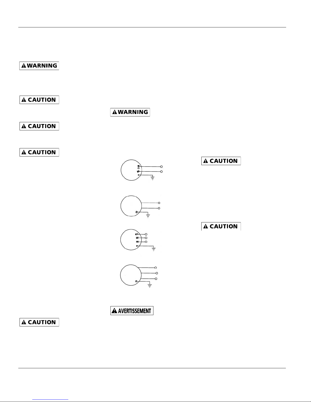
Single Speed
Line 1
Line 2
Single Speed
White
Black
Two Speed
H
C
L
Two Speed
White
Black
Red
Figure 2 - Wiring Diagram: 115 Volt Connection
ventilateur, ne pas compter sur un sélecteur comme
seul moyen de coupure de l’alimentation électrique.
Si l’interrupteur d’alimentation est hors de vue, le
verrouiller en position d’arrêt et apposer une
plaquette interdisant son utilisation. À défaut, un
choc électrique pourrait être fatal.
Line 1
Line 2
High
Common Line 1
Low
Common Line1
High
Low
l’installation ou
d’une réparation du
Minor and Routine
1.Disconnect and lock out power source
before servicing.
. Lubricate the motor sleeve bearings every six
2
months using S.A.E. 20 non-detergent oil.
Refer to Figure 2 for location of oil ports.
. Ball bearing motors are permanently
3
lubricated at the factory. No further
lubrication is necessary.
. Periodically clean the propellers, guard,
4
motor, and shutter of any accumulated dirt.
Parts Replacement
1. Refer to Figure 3 for parts placement.
2. Disconnect power before servicing.
3. Remove the four screws holding the guard
to the venturi panel. Remove the
guard/motor/propeller assembly.
4.Loosen the setscrew on blade hub and
remove the propeller.
Do not repair
damaged propellers. They
should be replaced with a properly balanced
replacement.
Maintenance
6. Loosen the nuts holding motor on guard and
remove motor. On split phase models, it is
also necessary to loosen and remove bolt and
nut holding wire brace to motor yoke tabs.
6. Reassemble the unit in reverse order of
disassembly.
Propeller is
installed hub first on motor
shaft, flush with end, and setscrew located over the
flat area.
2
Page 3

perating Instructions and Parts Manual
O
2SHE07 thru 2SHE36
2
6
Figure 3 — Replacement Parts Illustration
10, 13
1
12
11, 14
7
4
9
5
3
8
Replacement Parts List
Ref. 2SHE1661, 2SHE1871 2SHE18B1, 2SHE20 thru 2SHE24 2SHE30C1, 2SHE36D1
No. Description Qty. Qty. Qty.
1 Propeller 1 1 1
Shutter
2
3 Guard 1 1 1
4 Motor 1 1 1
5 Yoke brace — 1 1
6 Grommet — 4 —
7 10 x 3/4” Flat washer* — 4 4
3/8-24 x 1” HHCS screw*
8
3/8-24 Spinlock nut* — 1 1
9
10 #10-32 Spinlock nut* — 4 4
11
12 3/8 x 13/16” Flat washer*
13 #8-32 Spinlock nut* 4 — —
14 #10-32 x 1.0 HWH screw — — 8
(*) Standard hardware items, available locally.
#10-16 x 5/8” S.M. screw*
2SHE0721 thru 2SHE1221,
1
—
4
—
1
1
4
1
1
1
—
—
3
Page 4

Operating Instructions and Parts Manual
T
roubleshooting Chart
Symptom Possible Cause(s) Corrective Action
2SHE07 thru 2SHE36
Excessive noise 1. Dry motor bearings 1. Relubricate motor bearings
2. Loose propeller 2. Tighten setscrews in hub
3. Crooked or damaged propeller 3. Replace propeller
Fan inoperative 1. Blown fuse or open circuit breaker 1. Replace fuse or reset circuit breaker
2. Defective motor 2. Repair or replace motor
. Speed control set too low 3. Increase speed with controller
3
Insufficient air flow 1. Blocked intake or exhaust opening 1. Clear opening of obstruction or
increase size of opening
2. Low voltage 2. Determine cause and correct
3. Speed control set too low 3. Increase speed with controller
LIMITED WARRANTY: Fantech, Inc. warrants to the original purchaser that our products will be free from defects in material and workmanship for a period of one (1) year
from the date of shipment.
BY OPERATION OF LAW OR OTHERWISE, INCLUDING WITHOUT LIMITATION, MERCHANTABILITY AND FITNESS FOR A PARTICULAR PURPOSE WHETHER OR NOT THE PURPOSE OR
USE HAS BEEN DISCLOSED TO US IN SPECIFICATIONS, DRAWINGS OR OTHERWISE, AND WHETHER OR NOT OUR PRODUCTS ARE SPECIFICALLY DESIGNED AND/OR MANUFACTURED
BY US FOR PURCHASER'S USE OR PURPOSE.
This warranty does not cover any losses or damages due to misuse, accident, abuse, neglect, normal wear and tear, negligence (other than ours), unauthorized alteration,
use beyond rated capacity, or improper installation, maintenance or application. This warranty shall be null and void to the extent that purchaser supplied incorrect
information to us about the necessary product specifications or the environment in which the products were to be used, and our selection or design of the products for the
purchaser was based in part on such information.
If within thirty (30) days after purchaser's discovery of any warranty defects within the warranty period, purchaser notifies us thereof in writing, we shall, at our option,
repair, correct or replace F.O.B. point of manufacture, or refund the purchase price for, the products that we have found to be defective. Failure by purchaser to give such
written notice within the 30-day time period shall be deemed an absolute and unconditional waiver of purchaser's claim for such defects. Products repaired or replaced shall
be covered by this warranty for the remainder of the original warranty period or ninety (90) days from the date of shipment, whichever is longer.
Warranty claims should be sent to Fantech, Inc., Attn: Quality Department, 10048 Industrial Blvd., Lenexa, KS 66215. Included in the claim should be Order Number,
Model Numbers, Serial Numbers and a detailed description of the issues.
Purchaser assumes all other responsibility for any loss, damage or injury to persons or property arising out of the use of our products, either alone or in combination with
other products or components.
LIMITATION OF REMEDY AND LIABILITY: THE SOLE AND EXCLUSIVE REMEDY FOR BREACH OF ANY WARRANTY HEREUNDER SHALL BE LIMITED TO REPAIR, CORRECTION OR
REPLACEMENT, OR REFUND OF THE PURCHASE PRICE UNDER THE PRECEDING PARAGRAPH ENTITLED "LIMITED WARRANTY".
EMERSON VENTILATION PRODUCTS SHALL NOT BE LIABLE FOR DAMAGES CAUSED BY DELAY IN PERFORMANCE AND IN NO EVENT, REGARDLESS OF THE FORM OF THE CLAIM OR
CAUSE OF ACTION, SHALL OUR LIABILITY TO PURCHASER AND/OR ITS CUSTOMERS EXCEED THE PRICE PAID BY PURCHASER FOR THE SPECIFIC PRODUCT PROVIDED BY US THAT
GAVE RISE TO THE CLAIM OR CAUSE OF ACTION. PURCHASER AGREES THAT IN NO EVENT SHALL OUR LIABILITY TO PURCHASER AND/OR ITS CUSTOMERS EXTEND TO INCLUDE
INCIDENTAL, CONSEQUENTIAL OR PUNITIVE DAMAGES. The term "consequential damages" shall include, but not be limited to, loss of anticipated profits, business
interruption, loss of use or revenue, cost of capital, or loss or damage to property or equipment.
It is expressly understood that any technical advice furnished by us with respect to the use of our products is given without charge, and we assume no obligation or liability
for the advice given, or results obtained, all such advice being given and accepted.
THIS IS OUR SOLE AND EXCLUSIVE PRODUCT WARRANTY AND IS IN LIEU OF AND EXCLUDES ALL OTHER WARRANTIES, EXPRESS OR IMPLIED, ARISING
For Customer/Technical Support call (800) 565-3548
United States
1712 Northgate Blvd.,
Sarasota, FL. 34234
Phone: 800.747.1762;
941.309.6000
Fax: 800.487.9915; 941.309.6099
www.fantech.net; info@fantech.net
Canada
50 Kanalflakt Way,
Bouctouche, NB E4S 3M5
Phone: 800.565.3548;
506.743.9500
Fax: 877.747.8116; 506.743.9600
www.fantech.ca; info@fantech.ca
Fantech, reserves the right to modify, at any time and without notice, any or
all of its products’ features, designs, components and specifications to
maintain their technological leadership position.
Item #: 481810
Rev Date: 111408
 Loading...