

Page 1
Installation and Operational Manual
fantech
1WHC • 1WMS Series
Wall Mount Cabinet Exhaust and Supply Fans
Item #: 481844
Rev Date: 080813
United States
10048 Industrial Blvd., Lenexa, KS, 66215
Tel.: 800.747.1762 • Fax: 800.487.9915
Canada
50 Kanalflakt Way, Bouctouche, NB, E4S 3M5
Tel.: 800.565.3548 • Fax: 877.747.8116
Fantech, Inc. and Systemair
Mfg. certify that the ventilators shown herein are licensed
to bear the AMCA Seal. The
ratings shown are based
on tests and procedures
performed in accordance with
AMCA Publication 211 and
AMCA Publication 311 and
comply with the requirements
of the AMCA Certied Ratings
Program.
Page 2
2
Note Warning /
Information Technical
Important
note
Do not depend on any switch as the sole means of disconnecting power
when installing or servicing the fan. If the power disconnect is out-ofsight, lock it in the open position and tag to prevent application of power.
Failure to do so may result in fatal electrical shock.
1. Follow all local electrical and safety codes in the United States and
Canada, as well as the National Electrical Code (NEC) and the
Occupational Safety and Health Act (OSHA) in the United States, and
the Canadian Electric Code (CEC) in Canada.
2. Make certain that the power source conforms to the requirements of
your equipment.
3. Motor must be properly grounded by wiring with a grounded metal
raceway system, using a separate ground wire connected to the bare
metal of the motor frame or other suitable means.
Motor will restart without warning after protector trips.
Practical tip
information
4. Protect the power cable from coming into contact with sharp objects.
5. Do not kink the power cable and never allow the cable to come in
contact with oil, grease, hot surfaces, or chemicals.
Do not use in explosive atmospheres.
In America to reduce the risk of injury to persons, OSHA complying guards
are required when fan is installed within 8 feet of floor, ground, or
working level.
In Canada to reduce the risk of injury to persons, CSA complying guards
are required when fan is installed below 2.5 meters (8.2 feet) above floor
or grade level.
7. Always disconnect power source before working on or near a motor
or its connected load. If the power disconnect point is out-of-sight,
lock it in the open position and tag to prevent unexpected application
of power.
Description
Wall cabinet exhaust and supply fans are high volume, belt-drive fans used for ventilation in commercial, industrial, and agricultural applications with
static pressures up to 0.25 wg.
Fans are completely assembled, ready for installation. Units feature a galvanized venturi and housing, high efficiency propeller, rubber isolated, pressfit pillow block ball bearings , and totally enclosed, air over, ball bearing motors. All fans are UL Listed, Subject 705, and CSA approved . Guards
comply with United States OSHA Federal 1/2” opening requirement. Fan drives feature a variable pitch motor pulley to reduce fan speed by approximately 20% to provide proper air volume for specific applications.
1WMC54KY is UL Listed Only and features a polyester powder coated venturi and cast iron pillow block bearings. Models 1WMC36G7
and 1WMC48H7 are not UL listed or CSA certified.
Unpacking and inspection
1. When receiving fan, inspect carefully for any damage that may have occurred during transit. Check for loose, missing, or damaged parts.
2. Before installing, rotate the propeller to be sure there are no obstructions which would interfere with proper operation. Adjust as required.
Do not insert fingers or foreign objects into fan.
fantech
Page 3
Dimensions
3
D
A
D
C
B
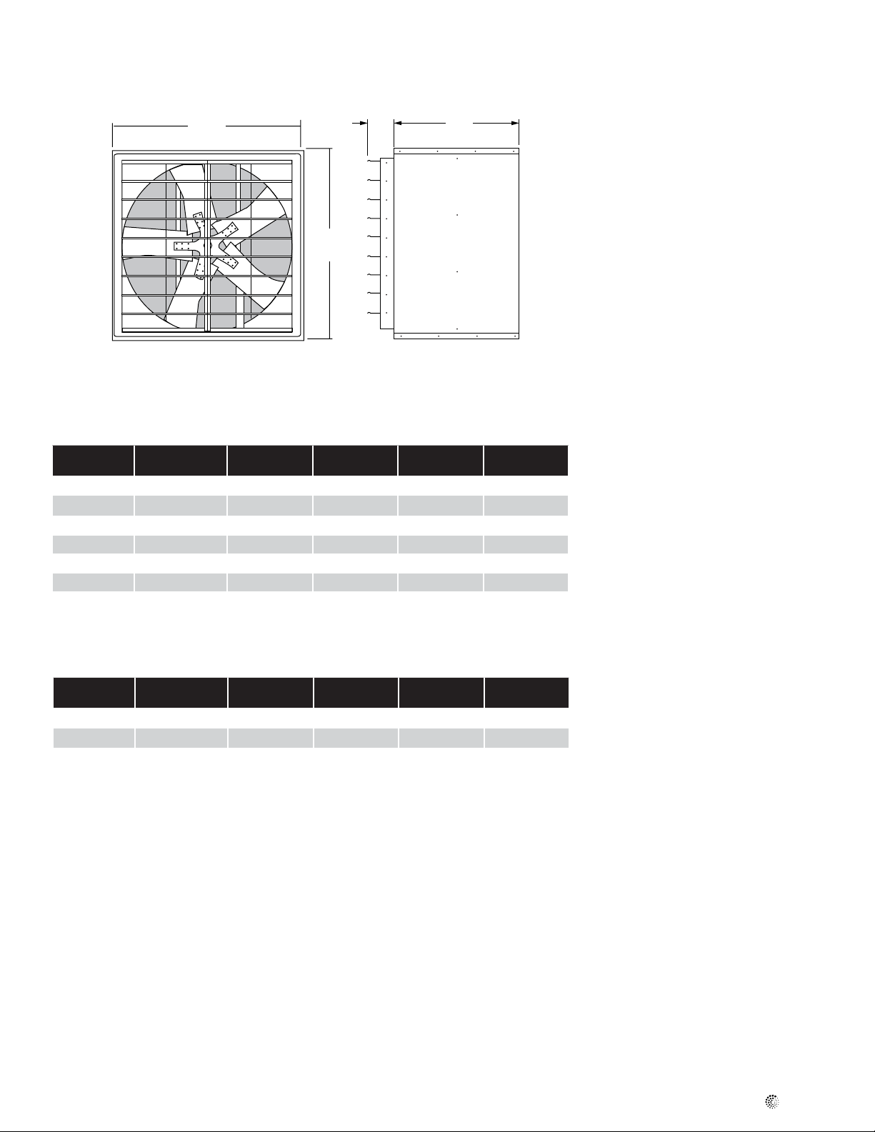
Figure 1: Dimensions
Table 1: Dimensional data Exhaust Fans
Model Fan size A B C Shipping Weight
1WMC24 24 28
1WMC30 30 34
1WMC36 36 40
1WMC42 42 46
1WMC48 48 54
1WMC54 54 60
/
4
1
/
4
1
/
4
1
/
4
1
/
4
1
/
4
28 1/
34
40 1/
46 1/
54 1/
60 1/
4
1
/
4
4
4
4
4
24 1/
25 1/
26 1/
28 1/
28 1/
47 3/
4
4
4
4
4
4
1
Dimensional information is in inches.
(Lbs)
123
176
196
242
288
635
Table 2: Supply Fans
Model Fan size A B C Shipping Weight
(Lbs)
1WMS24 24 28
1WMS36 36 40
1WMS48 48 54
1
/
4
1
/
4
1
/
4
28
40 1/
54 1/
1
/
4
4
4
30 143
32 1/
33 3/
4
4
208
311
Dimensional information is in inches.
fantech
Page 4
4
Installation
Drive Assembly
1. Place the motor base so that the anges are facing UP.
On motors with side conduit boxes. Interference may occur
with the side plates. In such instances, turn the base over
(anges down).
2. Secure the motor base to the frame tubes using the bolts provided.
Do not tighten the nuts at this time.
3. Mount the pulleys (motor and fan) on their respective shafts. A key is
included in the hardware package for the fan pulley. In all instances, the
larger diameter pulley mounts on the fan shaft. For some horsepower/
drive combinations, a bushed pulley is provided. The motor pulley
should be as close to the motor face as possible.
4. Slip the belt(s) into the fan pulley grooves.
5. Place the motor on the motor base so that the belt(s), hanging freely
Installation
1. Fans should be installed in a framed rigid
wall opening located where there will be no
obstruction to the ow of air into or out of
the fan.
NOT recommended for portable or
mobile installations or suspension
mounting with wire or chain.
2. Once a location has been determined; an
opening should be made in the wall and
framed to provide 1/4 to 1/2” total clearance
around the fan housing, (Refer to “Dimension” table).
3. Framing must be able to support the weight
of the fan assembly, (Refer to “Dimension”
table for weight). Reinforce wall, depending
on the construction of the wall.
4. Position fan assembly in the framed opening. It is recommended that, for maximum
weather protection, the fan housing extend
beyond the exterior of the building as little as
possible. Supply fans require a weather hood
to reduce the risk of moisture entering the
building.
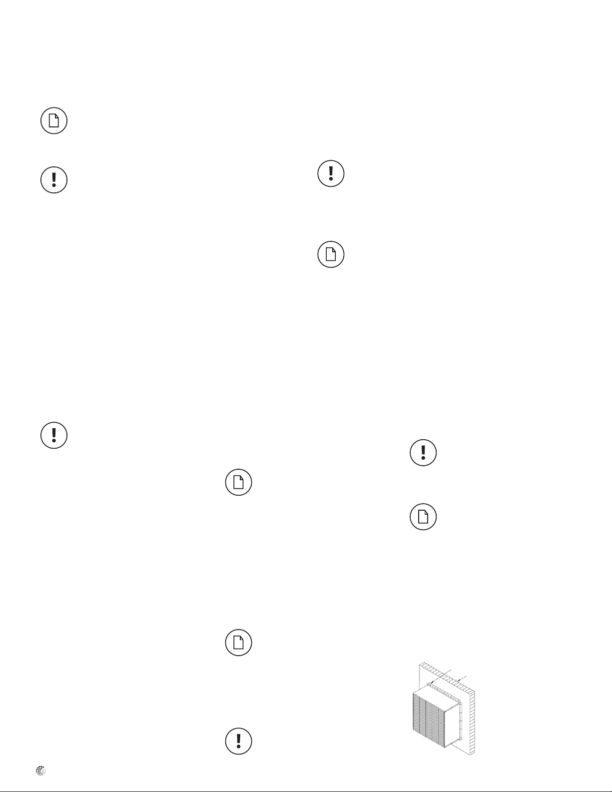
5. Attach (4) mounting angles to the fan housing and wall framing, (Refer to Figure 2).
a. Use pre-punched holes in mounting angles
as a template for drilling holes in fan
housing.
b. Bolt angles to housing using bolts, (5/16”
recommended, not supplied with unit). Every hole must be used. Do not skip holes.
c. Mounting angles must be securely
fastened to wall framing using hardware,
(not furnished) appropriate for the wall
construction.
Fan housing must be square in the
wall opening. The housing should be
level or tilted a maximum of 5° down
to the exhaust side.
6. Any gap between the fan housing and the
wall opening should be sealed from the
outside of the building.
7. Make certain that power source conforms to
the requirements of the fan.
8. Access the fan motor by removing the intake
guard.
The guard may be pivoted up, (or
down) by removing all but the (2)
top, (or bottom) corner fasteners.
Corner fasteners can act as hinges
to pivot guard and secure it out of
way. DO NOT overtighten fasteners
to avoid stripping the threads.
All electrical connections should be
made by a qualied electrician.
from the fan pulley, slip into the motor pulley grooves.
6. Position the motor on the base with the end of the motor shaft approximately even with the outer edge of the frame tubing. Align the
motor holes with the base holes and, using the bolts provided in the
hardware package, securely mount the motor. As the motor is drawn
down into position, tension will also be applied to the belt(s).
When assembling the motor and drive, the pulleys must be
aligned to keep the belt(s) straight. This is accomplished by
ensuring that the motor and fan pulley grooves are directly in
line with one another.
7. Adjust the motor base height as required to assure proper belt tension.
Proper tension is approximately 1/4” to 1/2” movement of the
belt when pressed at midspan under normal thumb pressure.
Do not overtighten the belt(s). However, new belts should be
tighter than used belts. On multiple belt installations, belts
should be matched and replaced only in sets.
9. Connect power to the motor using an
approved wiring method (motor terminal
connection data is provided on the motor
nameplate and on the motor terminal box
cover plate). Use adequate size wire for all
branch and feeder runs.
The fan motor must be securely and
adequately grounded to a suitable
electrical ground such as a
grounded water pipe or ground wire
system!
Motor cable should be routed
through fan housing using any one of
the knock-out positions provided.
Use grommet provided to protect
the motor cable from the knock-out
hole edges.
10. Before activating fan, inspect to be sure
that there are no obstructions or debris that
would interfere with propeller or the shutter.
11. Reposition intake guard in place and reinstall all fasteners.
12. Unit is ready for operation.
Mounting Angles
Wall
Figure 2 Mounting Angles
fantech
Page 5

Operation
1. Apply power to start and stop the fan. Be sure that the rotation of the propeller is correct as shown on the directional arrow on the unit.
2. Adjust for proper air volume.
a. Motor pulley is set from the factory for maximum fan speed/air volume.
b. Motor pulley can be adjusted by loosening set screw and unscrewing pulley by 1/2 turn (to keep set screw on at surface).
c. Adjust motor pulley until proper air volume is being exhausted.
If motor pulley has been adjusted, belt must be re-aligned by repositioning the propeller pulley on the fan shaft.
3. Upon initial operation, amps and, if possible, motor RPM should be checked against nameplate values to determine that fan is not being overloaded.
4. V-belt tension should be adjusted after rst 24 hours for proper operation. Belt(s) should deect 1/4” to 1/2” when depressed by thumb midpoint
between pulleys.
Maintenance
5
Do not depend on any switch as the sole means of disconnecting power when installing or servicing the fan. If the power disconnect is
out-of-sight, lock it in the open position and tag to prevent application of power. Failure to do so may result in fatal electrical shock.
1. Periodically check belt tension and adjust as necessary. Refer to “Operation” section.
2. When checking for belt tension, it is advisable to clean the intake guard, propeller, and exhaust shutter blades. This will remove any accumulated dirt
which could reduce air volume or cause propeller unbalance resulting in excessive vibration.
3. Fan pillow block bearings are prelubricated at the factory and require no further lubrication.
fantech
Page 6

6
Repair Parts List for Exhaust Fans
14
4
1
12
11
11
2
13
11
7
16
Figure 3: Repair parts illustration
Ref no. Description Part number for models:
WHV 24
1 Propeller 1
2 Motor 1
3 Intake guard 1
4 Exhaust shutter 1
5 Fan pulley 1
6 V-belt 1
7 Motor pulley 1
8 † Shaft/bearing assembly 1
9 1” Bearing, 6205 double dealed 2
10 Rubber bearing isolator 2
11 5/16-24 x .75 HHC screw* 16
12 5/16 x .688 x .065 F;at washer* 16
13 5/16-24 Spinlock nut* 16
14 10-32 x 1.0 HWH screw* 20-26
15 Guard retaining clip 12-14
16 Mounting angle 4
* Standard hardware item, available locally
† Replace entire shaft/bearing assembly (Item #8) unless facilities are available for pressing bearings onto shaft.
38, or 9, 10
15
5
14
6
fantech
Page 7

Troubleshooting
Symptom Possible causes Corrective Action
Excessive noise and/or
vibration
Fan inoperative 1. Blown fuse or open circuit breaker
Too much airow 1. Insufcient static pressure (SP)
1. Defective bearing or foreign material
inside bearing
2. Pulley not tight on shaft
3. Loose propeller
4. Loose belt(s)
5. Belt(s) are worn, oily or dirty
6. Misaligned pulley(s)
7. Crooked or damaged propeller
8. Motor or motor base not securely
anchored
9. Bent fan shaft
2. Broken belt
3. Loose pulley
4. Defective motor
5. Electricity turned off
2. Propeller running too fast
1. Replace entire shaft/bearing assembly
2. Check alignment and tighten setscrew
3. Tighten setscrews
4. Adjust tension
5. Clean or replace
6. Realign
7. Replace
8. Secure properly
9. Replace shaft/bearing assembly
1. Replace fuse or reset circuit breaker
2. Replace
3. Check alignment and tighten
4. Repair or replace
5. Contact local power company
1. Correct system pressure accordingly
2. Adjust variable pitch pulley to reduce propeller speed/air ow
7
Insufcient air ow 1. Shutter stuck shut
2. Fan speed too slow
3. Belt slippage
1. Repair
2. Check for proper pulley adjustment
3. Replace and/or adjust tension
fantech
Page 8

8
Warranty
Fantech, Inc. warrants to the original purchaser that our products will be
free from defects in material and workmanship for a period of one (1)
year from the date of shipment. THIS IS OUR SOLE AND EXCLUSlVE
PRODUCT WARRANTY AND IS IN LIEU OF AND EXCLUDES ALL OTHER
WARRANTIES, EXPRESS OR IMPLIED, ARISING BY OPERATION OF LAW
OR OTHERWISE, INCLUDING WITHOUT LIMITATION, MERCHANTABILITY
AND FITNESS FOR A PARTICULAR PURPOSE WHETHER OR NOT THE
PURPOSE OR USE HAS BEEN DISCLOSED TO US IN SPECIFICATIONS,
DRAWINGS DR OTHERWISE, AND WHETHER OR NOT OUR PRODUCTS
ARE SPECIFICALLY DESIGNED AND/OR MANUFACTURED BY US FOR
PURCHASER’S USE OR PURPOSE.
This warranty does not cover any losses or damages due to misuse,
accident, abuse, neglect, normal wear and tear, negligence [other than
ours), unauthorized alteration, use beyond rated capacity, or improper
installation, maintenance or application. This warranty shall be null and
void to the extent that purchaser supplied incorrect information to us
about the necessary product specifications or the environment in which
the products were to be used, and our selection or design of the
products for the purchaser was based in part on such information.
Limitation of Warranty and Liability
THE SOLE AND EXCLUSIVE REMEDY FOR BREACH OF ANY WARRANTY
HEREUNDER SHALL BE LIMITED TO REPAIR, CORRECTION OR
REPLACEMENT, OR REFUND OF THE PURCHASE PRICE UNDER THE
PRECEDING PARAGRAPH ENTITLED “LIMITED WARRANTY”. FANTECH
VENTILATION PRODUCTS SHALL NOT BE LIABLE FOR DAMAGES
CAUSED BY DELAY IN PERFORMANCE AND IN NO EVENT,
REGARDLESS OF THE FORM OF THE CLAIM OR CAUSE OF ACTION,
SHALL OUR LIABILITY TO PURCHASER AND/OR ITS CUSTOMERS
EXCEED THE PRICE PAID BY PURCHASER FOR THE SPECIFIC PRODUCT
PROVIDED BY US THAT GAUE RISE TO THE CLAIM OR CAUSE OF
If within thirty (30) days after purchaser’s discovery of any warranty
defects within the warranty period, purchaser notifies us thereof in
writing, we shall, at our option, repair, correct or replace F.O.B. point of
manufacture, or refund the purchase price for, the products that we have
found to be defective. Failure by purchaser to give such written notice
within the 30-day time period shall be deemed an absolute and
unconditional waiver of purchaser’s claim for such defects. Products
repaired or replaced shall be covered by this warranty for the remainder
of the original warranty period or ninety (90) days from the date of
shipment, whichever is longer.
Warranty claims should be sent to Fantech, Inc.,
Attn: Quality Department, 10048 Industrial Blvd., Lenexa, KS 66215.
Included in the claim should be Order Number, Model Numbers, Serial
Numbers and a detailed description of the issues.
Purchaser assumes all other responsibility for any loss, damage or injury
to persons or property arising out of the use of our products, either
alone or in combination with other products or components.
ACTION. PURCHASER AGREES THAT IN NO EVENT SHALL OUR
LIABILITY TO PURCHASER AND/OR ITS CUSTOMERS EXTEND TO
INCLUDE INCIDENTAL, CONSEQUENTIAL OR PUNITIVE DAMAGES. The
term “consequential damages” shall include, but not be limited to,
loss of anticipated profits, business interruption, loss of use or revenue,
cost of capital, or loss or damage to property or equipment.
It is expressly understood that any technical advice furnished by us with
respect to the use of our products is given without charge, and we
assume no obligation or liability for the advice given, or results obtained,
all such advice being given and accepted.
Warning
Fantech products are designed and manufactured to provide reliable
performance, but they are not guaranteed to be 100% free from
defects. Even reliable products will experience occasional failures and
this possibility should be recognized by the user. If these products are
used in a life support ventilation system where failure could result in loss
or injury, the user should provide adequate backup ventilation,
supplementary natural ventilation, failure alarm system, or acknowledge
willingness to accept the risk of such loss or injury.
For Customer/Technical Support call (800) 565-3548
fantech
Page 9

Notes
9
fantech
Page 10

10
Notes
fantech
Page 11

Notes
11
fantech
Page 12

fantech
Fantech reserves the right to make technical changes.
For updated documentation please refer to www.fantech.net
Fantech®
 Loading...