

Page 1

Italiano English Deutsch Français Español Português
LIBRETTO ISTRUZIONI
INSTRUCTIONS BOOKLET
BEDIENUNGSSANLEITUNG
LIVRET D’INSTRUCTIONS
MANUAL DE INSTRUCCIONES
MANUAL DE INSTRUÇÕES
азлнкмдсаь ий щдлигмДнДсаа
Cod. 110030294 (FLIPPER)
INSTRUKCJE OBSŁUGI
на русском
языке
Polska
Ed. 2013
Page 2

Gentile Signora/Signore, congratulazioni!
Lei ha acquistato una cappa di prestigio e di sicura qualità. Perché Lei possa ottenere le migliori
prestazioni, Le suggeriamo di seguire con attenzione le istruzioni per l’uso e manutenzione che
troverà in questo libretto; inoltre, per ordinare i filtri di ricambio al carbone attivo utilizzi l’apposito
tagliando che troverà allegato alla copertina.
Dear Sir/Madam, congratulations!
You have purchased a prestigious range hood of guaranteed quality. For best results, we suggest that
you carefully follow the operating and maintenance instructions provided in this booklet; in addition, to
order spare charcoal filters, use the special coupon on the cover.
Verehrte Kundin, verehrter Kunde
Kompliment! Sie haben eine qualitativ hochwertige Dunstabzugshaube erworben. Um ihre
Leistungsfähigkeit optimal nutzen zu können, sollten Sie die beiliegende Gebrauchs- und
Wartungsanleitung sorgfältig durchlesen und befolgen. Für die Bestellung der Ersatz-Aktivkohlefilter
verwenden Sie bitte den Coupon, der dem Deckblatt beiliegt.
Chère Madame/Cher Monsieur, félicitations!
Vous venez d’acheter une hotte haut de gamme. Pour en tirer les performances les meilleures
veuillez lire avec attention le mode d’emploi et la maintenance que vous trouvez dans ce manuel;
pour commander les filtres de rechange au carbone actif veuillez vous servir du coupon annexé à la
couverture.
Enhorabuena Señora/Señor!
Ha comprado una campana extractora de prestigio y calidad segura. Para que pueda obtener las
mejores prestaciones, le sugerimos seguir con atención las instrucciones contenidas en este manual
para el uso y el mantenimiento. Para pedir los filtros de recambio de carbón activo, utilice el cupón
adjunto a la cubierta.
Prezada Senhora, prezado Senhor, parabéns!
Foi feita a aquisição de uma coifa de prestígio e de excelente qualidade. Para que possa ser obtido
o melhor desempenho, sugerimos que sejam seguidas com atenção as instruções para o uso e a
manutenção que estão apresentadas neste manual; além disso, para a solicitação dos filtros de
reposição de carvão ativado, use o cupão anexo à capa.
З˚ ФЛУ·ОЛ ФТЪЛКМУ Л ‚˚ТУНУН‡˜ТЪ‚ММУ ‚˚ЪflКМУ ЫТЪУИТЪ‚У. СОfl ЪУ„У, ˜ЪУ·˚ УМУ ‰‡‚‡ОУ М‡ЛОЫ˜¯Л
БЫО¸Ъ‡Ъ˚, НУПМ‰ЫП ‚МЛП‡ЪО¸МУ ТО‰У‚‡Ъ¸ ЛМТЪЫНˆЛflП ФУ ˝НТФОЫ‡Ъ‡ˆЛЛ Л ЫıУ‰Ы, НУЪУ˚ ‚˚ М‡И‰Ъ ‚ ˝ЪУП
ЛБ‰‡МЛЛ; НУП ЪУ„У, ‰Оfl Б‡Н‡Б‡ Б‡Ф‡ТМ˚ı ЩЛО¸ЪУ‚ М‡ ‡НЪЛ‚ЛУ‚‡ММУП Ы„О ЛТФУО¸БЫИЪ ТФˆЛ‡О¸М˚И Ъ‡ОУМ,
НУЪУ˚И ‚˚ ПУКЪ М‡ИЪЛ ФЛНФОММ˚П Н У·ОУКН.
Szanowni Państwo
Gratulujemy!
Zakupiliście prestiżowy okap kuchenny o gwarantowanej jakości. Dla uzyskania najlepszych wyników zalecamy, by starannie przestrzegać instrukcji obsługi i konserwacji zawartych w tej broszurze. Ponadto,
do zamawiania zapasowych fi ltrów z węglem drzewnym, wykorzystywać specjalny kupon załączony na
okładce.
Page 3
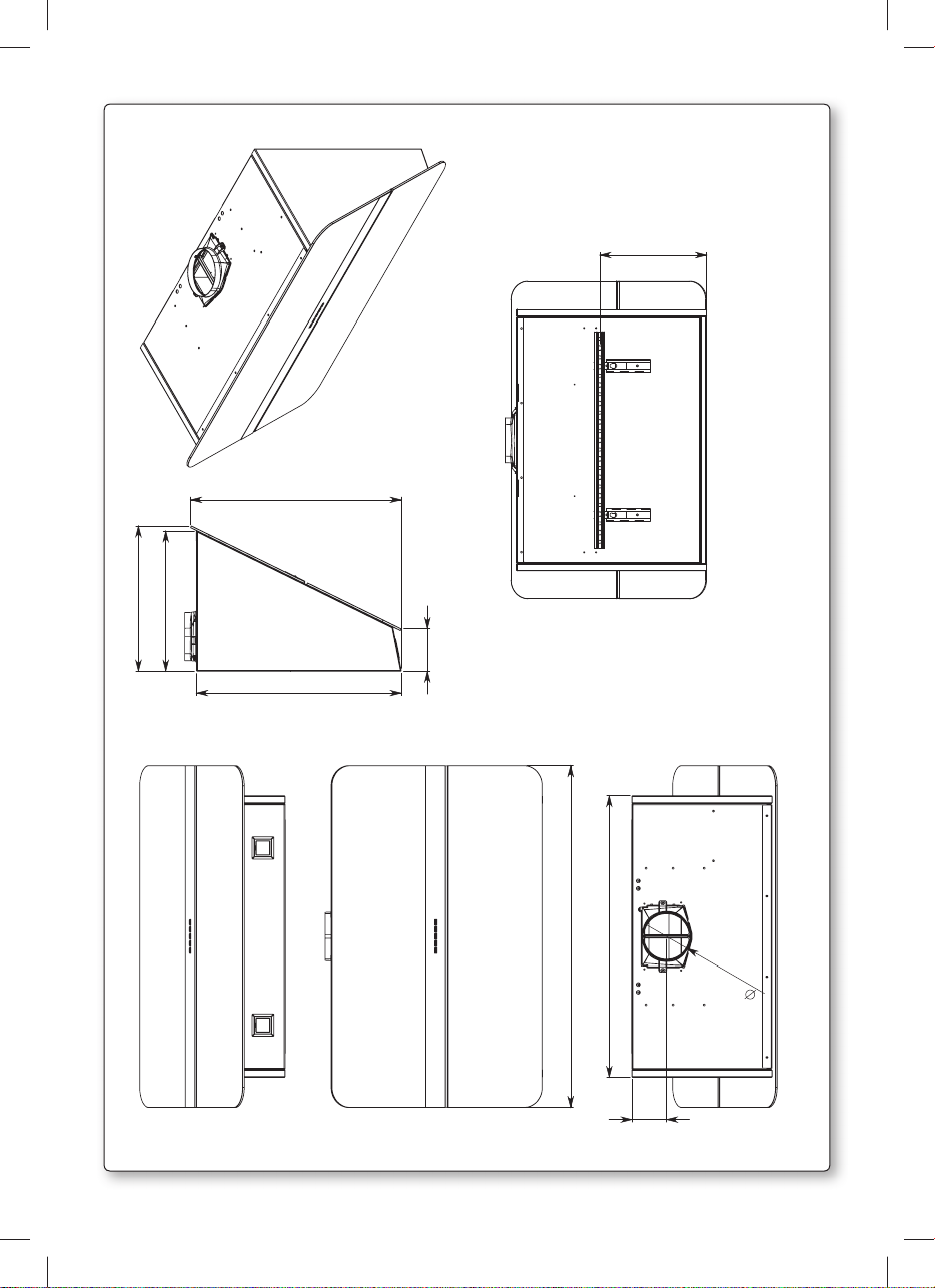
362
349
525
510
106
287
/h
3
FLIPPER 85 600 m
850
700
86,2
120
1
Page 4
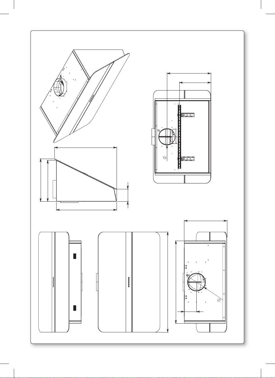
362
349
525
510
106
150
400
287
/h
3
FLIPPER 85 800 m
362
850
700
150
104
2
Page 5
1 2
ø4mm
V3
L
1
2
A
ø8
1
3
A
V1
287
X
3 4 - optional
1
S
T
2
3
R
B
3
V4
5
3
2
C
4
L
H
2
5
3
1
2
G
V2
1
Page 6
Back outlet available only with 800 m3/h blower
6
1
2
3
Connettore comando
Panel control connector
PRESS
7
6
8
5
4
Cavo alimentazione
Power cord
9
x4
4
Page 7
I
LIBRETTO ISTRUZIONI
A
Se l’apparecchio dovesse essere venduto o trasferito ad un’altra persona, assicurarsi che il
Queste avvertenze sono state redatte per la vostra sicurezza e per quella degli altri, Vi preghia-
AVVERTENZE
È molto importante che questo libretto istruzioni sia conservato insieme all’apparecchiatura
per qualsiasi futura consultazione.
libretto venga fornito assieme, in modo che il nuovo utente possa essere messo al corrente del
funzionamento della cappa e delle avvertenze relative.
mo, dunque, di volerlo leggere attentamente prima d’installare e di utilizzare l’apparecchio.
Questo apparecchio non deve essere utilizzato da bambini o persone infermi a meno che non
siano adeguatamente controllate da persone responsabili che si assicurino che l’apparecchio
sia utilizzato in sicurezza.
I bambini devono essere controllati da persona responsabile per assicurarsi che non giochino
con l’apparecchio.
Il lavoro di installazione deve essere eseguito, da installatori competenti e qualificati, secondo
le norme in vigore.
Se il cavo di alimentazione è danneggiato, esso deve essere sostituito dal costruttore o dal
suo servizio assistenza tecnica o comunque da una persona con qualifica similare, in modo da
prevenire ogni rischio.
Ogni eventuale modifica che si rendesse necessaria all’impianto elettrico per installare la cappa
dovrà essere eseguita solo da persone competenti.
È pericoloso modificare o tentare di modificare le caratteristiche di questo impianto. In caso di
riparazioni o mal funzionamento dell’apparecchio, non tentare di risolvere da soli il problema.
Le riparazioni effettuate da persone non competenti possono provocare danni.
Per eventuali interventi rivolgersi ad un Centro Assistenza Tecnica autorizzato ad eseguire parti
di ricambio.
Controllare sempre che tutte le parti elettriche, (luci, aspiratore), siano spente quando l’apparecchio non viene usato. Leggere tutto il libretto istruzioni prima di effettuare operazioni sulla cappa.
L’utilizzo della cappa non può essere diverso da quello di aspiratori di fumi di cottura su cucine
domestiche.
Qualsiasi utilizzo diverso da questo solleva il costruttore da qualsiasi responsabilità.
Il peso massimo complessivo di eventuali oggetti posizionatio appesi (ove previsto) sulla
cappa non deve superare 1,5 Kg.
Dopo l’installazione delle cappe in acciaio inox bisogna eseguire la pulizia della stessa per
rimuovere i residui di collante protettivo e le eventuali macchie di grasso o oli.
Per questa operazione il costruttore raccomanda l’utilizzo delle salviette in dotazione, disponibili anche in acquisto.
L’utilizzo di altre tipologie di detergenti solleva il costruttore dalla responsabilità sui danni che
ne potrebbero derivare.
E’ assolutamente vietato posizionare arti o qualsiasi altra parte del corpo umano o di un animale in prossimità del raggio di azione del movimento del carrello mobile della cappa delimitato
dalla cornice fissata sulla base del mobile (vedi figura A).
Non posizionare pentole, manici di pentole o qualsiasi altro oggetto nel raggio di azione del
movimento del carrello mobile della cappa come sopra specificato.
Fare attenzione che le parti accessibili della cappa potrebbero essere calde durante o al
termine della cottura.
Il vetro superiore VS e il pannello proteggi luce VL sono fissati al corpo cappa mediante magneti. In caso di distacco di VS VL dal corpo cappa per cause accidentali, verificarne l’integrità
e riposizionarlo nella sua sede. In caso contrario chiamare l’assistenza tecnica.
Italiano
5
Page 8
Non collegare l’apparecchio a condotti di scarico dei fumi prodotti dalla combustione (caldaie,
Controllare le friggitrici durante l’uso: I’olio surriscaldato potrebbe infiammarsi.
SICUREZZA AVVERTENZE
L’impianto elettrico è munito di collegamento a terra secondo le norme di sicurezza internazio-
nali; è inoltre conforme alle normative Europee sull’antidisturbo radio.
caminetti,ecc). Verificare che la tensione di rete corrisponda a quella riportata dalla targhetta
posta all’interno della cappa.
- Assicurarsi che vi sia una adeguata ventilazione nella stanza se la cappa è utilizzata con altri
apparecchi che utilizzano combustibili come gas o altro.
- Non accendere fiamme libere sotto la cappa.
- Non collegare l’apparecchio a condotti di scarico dei fumi prodotti dalla combustione (caldaie, caminetti, ecc).
- Assicurarsi che tutte le normative vigenti sullo scarico dell’aria all’esterno del locale siano
rispettate prima dell’utilizzo della cappa.
Prima di procedere a qualsiasi operazione di pulizia o di manutenzione, disinserire l’appa-
recchio togliendo la spina o agendo sull’interruttore generale. La casa costruttrice declina
ogni responsabilità per eventuali danni che possano, direttamente o indirettamente, essere
causati a persone, cose ed animali domestici in conseguenza alla mancanza di tutte le prescrizioni indicate nell’apposito libretto istruzioni e concernenti, specialmente, le avvertenze
in tema di installazione, uso e manutenzione dell’apparecchio.
- Rischio di incendio se la pulizia non è condotta secondo le istruzioni del presente libretto.
ATTENZIONE: parti accessibili possono essere calde quando usate con apparecchi di cottura.
- La lunghezza massima della vite di fissaggio del camino (fornita dal fabbricante) è di 10 mm.
AVVERTENZA: l’installazione delle viti o dei dispositivi di fissaggio non conforme alle presenti
istruzioni può comportare rischi di natura elettrica.
6
B
C
CARATTERISTICHE TECNICHE
I dati tecnici dell’elettrodomestico sono riportati su delle targhette, posizionate all’interno della
cappa.
INSTALLAZIONE
(parte riservata solo a persone qualificate per il montaggio della cappa)
La distanza minima: distanza fra la parte più alta dell’apparecchiatura per la cottura e la parte
più bassa della cappa da cucina. In generale, quando la cappa da cucina è posta su un’apparecchiatura a gas, questa distanza deve essere almeno 65 cm (vedi figura 02). Tuttavia sulla
base di un’interpretazione della norma EN60335-2-31 del 11-07-2002 da parte del TC61 (subclause 7.12.1 meeting 15 agenda item 10.11), nel caso della cappa Flipper, tale distanza minima
tra piano cottura e parte inferiore della cappa può essere ridotta a 53 cm. Se le istruzioni del
piano di cottura a gas specificano una distanza maggiore, bisogna tenerne conto.
Nella versione aspirante il tubo completo di uscita dei fumi deve avere un diametro non inferire
a quello del raccordo della cappa. Nei tratti orizzontali il tubo deve avere una leggera inclinazione (10% circa) verso l’alto per convogliare meglio l’aria all’esterno dell’ambiente.
Ridurre al minimo le curve, verificare che i tubi abbiano una lunghezza minima indispensabile.
Rispettare le norme vigenti sullo scarico dell’aria all’esterno. In caso di utilizzo contemporaneo
di altre utenze (caldaie, stufe, caminetti, ecc.) alimentate a gas o con altri combustibili, provvedere ad una adeguata ventilazione del locale in cui avviene l’aspirazione dei fumi, secondo le
norme vigenti. Istruzioni di montaggio: vedi sez. “O” del presente manuale.
Page 9
D
E
ALLACCIAMENTO ELETTRICO
(parte riservata solo a persone qualificate per l’allacciamento)
ATTENZIONE!
Prima di effettuare qualsiasi operazione all’interno della cappa scollegare l’apparecchio
dalla rete elettrica.
Assicurarsi che non vengano scollegati o tagliati fili elettrici all’interno della cappa; nel caso si verifichino tali situazioni contattare il centro assistenza più vicino. Per l’allacciamento
elettrico rivolgersi a personale qualificato.
Il collegamento deve essere eseguito in conformità con le disposizioni di legge in vigore.
Controllare che la presa di corrente e l’impianto elettrico possano sopportare il carico dell’apparecchio (vedere targhetta caratteristiche tecniche al punto B). Alcuni tipi di apparecchi
possono essere dotati di cavo senza spina; in questo caso, utilizzare una spina del tipo “normalizzato” o una scatola di giunzione, tenendo conto che:
- il filo giallo-verde deve essere utilizzato per la messa a terra,
- il filo blu/bianco deve essere utilizzato per il neutro,
- il filo marrone/nero deve essere utilizzato per la fase, il cavo non deve entrare in contatto
con parti calde aventi temperature superiori a 70°C.
- montare sul cavo di alimentazione una spina adatta al carico e collegarla ad una adeguata
spina di sicurezza.
Se un apparecchio fisso non è provvisto di cavo di alimentazione e di spina, o di altro dispositivo che assicuri la disconnessione dalla rete, con una distanza di apertura dei contatti che
consenta la disconnessione completa nelle condizioni della categoria di sovratensione III, le
istruzioni devono indicare che tali dispositivi di disconnessione devono essere previsti nella
rete di alimentazione conformemente alle regole di installazione.
Il cavo di terra giallo/verde non deve essere interrotto dall’interruttore.
Prima di collegare l’apparecchio alla rete elettrica, controllare che:
- la tensione d’alimentazione corrisponda a quella indicata dalla targhetta caratteristiche
tecniche.
- la presa di terra sia corretta e funzionale.
- l’impianto di alimentazione sia munito di efficace collegamento di terra secondo le norme
vigenti.
- la presa o l’interruttore omnipolare usati siano facilmente raggiungibili con l’apparecchiatu-
ra installata.
La casa costruttrice declina ogni responsabilità nel caso le norme di sicurezza non vengano
rispettate.
CAPPA DI VERSIONE
AD EVACUAZIONE ESTERNA (aspirante)
In questa versione i fumi e i vapori della cucina vengono convogliati verso l’esterno attraverso
un tubo di scarico.
Il convogliatore di scarico che sporge sulla parte superiore della cappa deve essere collegato
con un tubo che conduce i fumi e i vapori in una uscita esterna. In questa versione vanno tolti
i filtri al carbone attivo se esistenti; per l’estrazione vedere istruzioni al punto F. Quando la
cappa da cucina viene utilizzata contemporaneamente ad altri apparecchi che impiegano gas
o altri combustibili, il locale deve disporre di sufficiente ventilazione secondo le norme vigenti.
Deviazione per la Germania:
Quando la cappa da cucina e apparecchi alimentati con energia diversa da quella elettrica
sono in funzione simultaneamente, la pressione negativa nel locale non deve superare i 4
Pa (4 x 10⁻⁵ bar).
Italiano English Deutsch Français Español Português
на русском
языке
Polska
7
Page 10
F
CAPPA DI VERSIONE A RICICLO INTERNO (filtrante)
In questa versione l’aria passa attraverso i filtri di carbone attivo per essere purificata e viene
riciclata nell’ambiente cucina.
Controllare che i filtri al carbone attivo siano montati sul motore, in caso negativo applicarli
come indicato nelle istruzioni al punto H.
Se la cappa viene predisposta in versione filtrante rimuovere la valvola di non ritorno montata
sul raccordo di uscita del motore.
Per il miglior rendimento si consiglia di utilizzare la terza velocità in presenza di forti odori
e vapori, la seconda velocità nelle condizioni normali, la prima velocità per mantenere l’aria
pulita con bassi consumi di energia elettrica. Si consiglia di mettere in funzione la cappa
quando si inizia a cuocere e manteneria in funzione fino alla scomparsa degli odori.
G
FUNZIONAMENTO
PULSANTIERA ELETTRONICA
Pulsante luce
• ON: luce accesa (pulsante illuminato);
• OFF: luce spenta;
Pulsante -
Premendo il tasto si riduce la velocità del motore.
La velocità 1, 2 e 3 è visualizzata dal n° di led accesi escluso led luce e timer.
Pulsante +
Premendo il tasto si incrementa la velocità del motore.
La velocità 1,2 e 3 è visualizzata dal n° di led accesi escluso led luce e timer.
(Nella versione a 4 velocità il tasto + presenta una luce intermittente. La 4° velocità o intensiva
è temporizzata e dopo circa 15 minuti il motore passa automaticamente in 3° velocità).
Pulsante modalità
Funzione: accensione e spegnimento motore cappa.
La funzione velocità desiderata permette di avviare il motore con l’ultima velocità selezionata
prima del precedente spegnimento.
Optional: versione con radiocomando (disponibile solo su alcune versioni).
AVVERTENZE (versione con radiocomando):
Posizionare l’apparecchio lontano da sorgenti di onde elettromagnetiche che potrebbero
interferire con l’elettronica della cappa
Distanza massima di funzionamento 5 metri. Tale distanza può variare in difetto in funzione
delle interferenze elettromagnetiche di altri apparecchi.
Pulsante luce del telecomando: on/off luce.
Pulsante – e + decremento/incremento velocità (per avviare il motore premere indifferentemente tasto + o in tasto -.
Pulsante timer: vedi istruzione sottostante.
Pulsante timer e saturazione filtri
• Questa funzione permette lo spegnimento automatico della cappa dopo 15 minuti di funzionamento alla velocità precedentemente impostata (pulsante con luce intermittente).
• Dopo circa 30 ore di funzionamento il pulsante propone il lavaggio dei filtri metallici (pulsante illuminato di rosso). Per disattivare l’allarme premere il pulsante timer per qualche
secondo fino allo spegnimento della luce rossa. Successivamente spegnere la cappa e
riaccenderla per verificare l’annullamento dell’allarme.
8
Page 11

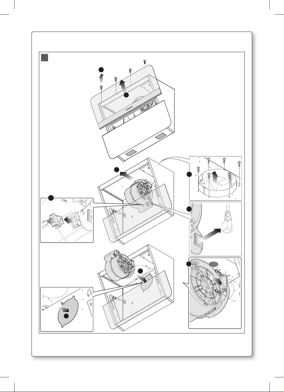
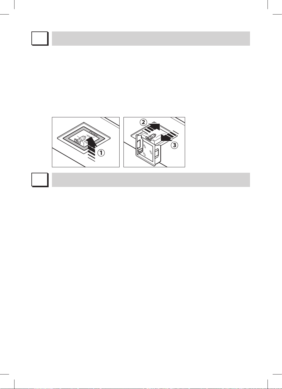
H
FILTRI ISTRUZIONI PER L’ESTRAZIONE E LA SOSTITUZIONE
1. FILTRI METALLICI
Per rimuovere il filtro metallico antigrasso, aprire l’anta delicatamente come illustrato in
fig. 2. Per rimuovere i filtri metallici agire sulla maniglia.
2. FILTRI AL CARBONE ATTIVO
Rimuovere i filtri metallici secondo le indicazioni sezione H1.
A questo punto si accede facilmente ai due filtri che sono agganciati sul lato dx e sx del
convogliatore. Per il montaggio/sostituzione vedi figura.
Per ordinare i nuovi filtri carbone rivolgersi al distributore/rivenditore.
SOLO PER ITALIA: Scaricare l’apposito modulo ordine filtro sul sito:
www.falmec.com (accedere sul menù a tendina assistenza).
ILLUMINAZIONE MONTAGGIO E SOSTITUZIONE
I
1. FARETTO LED (Flipper)
In questo caso la cappa è dotata di illuminazione di faretti led ad alta efficienza, basso
consumo e durata molto elevata in condizioni di normale utilizzo. La sostituzione del faretto
led deve essere fatta solo da tecnici qualificati utilizzando solo ricambi originali.
2. FARETTO (Flipper/E)
Per sostituire la lampada del “Square halogen light”:
a) Accertarsi che l’apparecchio sia scollegato dalla rete elettrica.
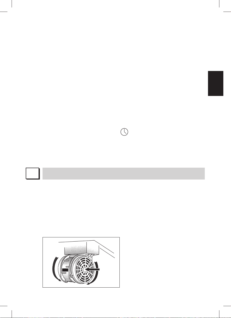
b) Aprire completamente il pannello fino ad un angolo di 90° (vedi figura) premendo su PUSH
c) Sostituire la lampada con una analoga (alogena max 20 W, 12 Volt attacco G4).
d) Richiudere i pannello. Se il pannello non si richiude correttamente ripetere l’operazione al
punto b.
Italiano
9
Page 12
L
MANUTENZIONE E PULIZIA
Una costante manutenzione garantisce un buon funzionamento ed un buon rendimento nel
tempo. Particolari attenzioni vanno rivolte ai filtri metallici antigrasso ed ai filtri al carbone
attivo, infatti la pulizia frequente dei filtri e dei loro supporti garantisce che sulla cappa non si
accumulino grassi che sono pericolosi per la facilità di incendio.
1. FILTRI ANTIGRASSO METALLICI
Hanno la funzione di trattenere le particelle grasse in sospensione, pertanto si consiglia di
lavarli ogni mese in acqua calda e detersivo evitando di piegarli. Attendere che siano ben
asciutti prima di rimontarli.
2. FILTRI AL CARBONE ATTIVO
Hanno la funzione di trattenere gli odori presenti nel flusso d’aria che li attraversa. L’aria
depurata per successivi passaggi attraverso i filtri viene rimessa nell’ambiente cucina. l
filtri al carbone attivo non possono essere lavati e vanno sostituiti mediamente ogni 3-4
mesi (dipende poi dall’uso). Per la sostituzione dei filtri al carbone attivo seguire le istru-
zioni come al punto H2.
3. PULIZIA ESTERNA
Si raccomanda di pulire le superfici esterne delle cappe almeno ogni 15 giorni per evitare
che le sostanze oleose o grasse possano intaccare le superfici in acciaio.
La pulizia della cappa va eseguita usando un panno umido con detersivo liquido neutro o
con alcool denaturato.
Nel caso di materiale con trattamento antimpronta (Fasteel) eseguire la pulizia solo con
acqua e sapone neutro utilizzando un panno morbido avendo cura di risciacquare e
asciugare accuratamente. Non si devono utilizzare prodotti contenenti sostanza abrasive,
panni con superfici ruvide o panni comunemente in commercio per la pulizia dell’acciaio.
L’utilizzo di sostanze abrasive e panni ruvidi danneggerà irreparabilmente il trattamento
superficiale dell’acciaio.
Conseguenza diretta del non rispetto di tali avvertenze sarà il deterioramento irreversibile
della superficie dell’acciaio.
Tali avvertenze dovranno essere conservate insieme al libretto istruzioni della cappa.
Il produttore declina ogni responsabilità qualora non vengano rispettate tali istruzioni.
4. PULIZIA INTERNA
É vietata la pulizia di parti elettriche o parti relative al moto re all’interno della cappa, con
liquidi o solventi;
Effettuare tutte queste operazioni scollegando preven tivamente l’apparecchio dalla rete
Non usare prodotti contenenti abrasivi.
elettrica.
M
La sua nuova apparecchiatura è coperta da garanzia. Le condizioni di garanzia sono riportate
10
GARANZIA
per esteso sull’ulti ma pagina di copertina di questo libretto.
La casa costruttrice non risponde delle possibili ine sattezze, imputabili ad errori di stampa
o di trascrizio ne, contenute nel presente libretto. Si riserva di appor tare ai propri prodotti
quelle modifiche che ritenesse necessarie o utili, anche nell’interesse dell’utenza, senza
pregiudicare le caratteristiche essenziali di fun zionalità e di sicurezza.
Page 13

N
ISTRUZIONI MONTAGGIO CAPPA
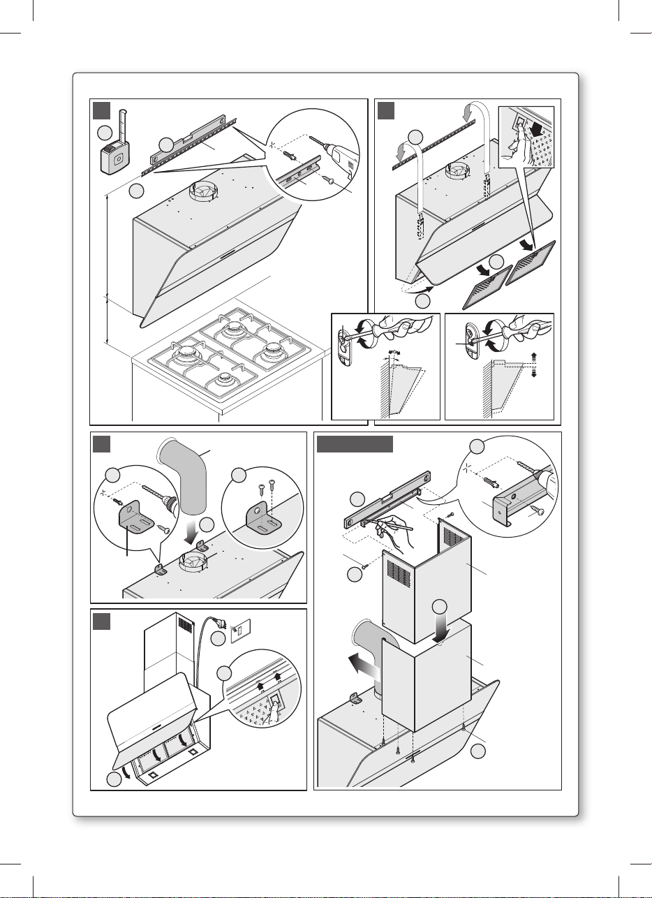
Fase 1 (fig. 1)
- Appoggiare alla parete la barra di sostegno (A), ad un’altezza dal piano cottura determinata
dalla somma delle quote X+287 mm.
- Controllare con una bolla di livello l’allineamento orizzontale e segnare alle estremità della
barra n° 2 punti di foratura.
- Forare, inserire n° 2 tasselli ad espansione ø 8mm e fissare la barra con le relative viti (V1).
Fase 2 (fig. 2)
- Agganciare la cappa alla barra di sostegno.
- Aprire l’anta delicatamente e rimuovere i filtri metallici.
- Regolare l’allineamento della cappa tramite le viti delle attaccaglie. La vite superiore (B)
regola la distanza dalla parete, quella inferiore (C) lo scorrimento verticale.
Fase 3 (fig. 3)
- Per evitare lo sganciamento della cappa dovuto ad una pressione sottostante, installare le
staffe di sicurezza (S) come illustrato in figura.
- Nel caso di versione aspirante collegare il raccordo di uscita del ventilatore (R) allo scarico
esterno mediante idonea tubazione (T). Nel caso di installazione con uscita posteriore vedi
anche figura 6.
- Eseguire il collegamento elettrico solo dopo aver disinserito l’alimentazione elettrica della
cappa.
Fase 4 (optional) (fig. 4)
- Inserire la prolunga (H) nel camino (G) e fissare l’assieme al corpo cappa mediante le viti (V2).
- Fare scorrere la prolunga (H) fino a raggiungere l’altezza desiderata.
- Trovata la posizione ottimale, appoggiare alla parete la staffa (L), controllare con una bolla di
livello l’allineamento orizzontale e segnare alle estremità n°2 punti di foratura.
- Forare, inserire n° 2 tasselli ad espansione ø 4mm e fissare la staffa (L) con le relative viti (V3).
- Avvitare con le viti (V4) la prolunga (H) alla staffa (L).
Fase 5
- Rimontare sulla cappa i filtri metallici, chiudere l’anta della cappa.
- Alimentare elettricamente la cappa rispettando le norme vigenti (sez. D).
Italiano
11
Page 14
GB
INSTRUCTIONS BOOKLET
A
WARNINGS
This instruction booklet must be kept together with the appliance for future reference. If the
appliance is sold or consigned to other parties, check that the booklet is supplied with it, to
ensure that the new user has the correct information on the operation of the range hood and
is aware of the warnings. These warnings have been provided for the your safety and the
safety of others. As a result, please read them carefully before installing and operating the
appliance.
This appliance is not intended for use by young children or infirm persons unless they have
been adequately supervised by a responsible person to ensure that they can use the appliance
safely. Young children should be supervised to ensure they do not play with the appliance.
The appliance must be installed by qualified personnel, in accordance with the standards in
force. If the supply cord is damaged, it must be re-placed by the manufacturer, its service
agent or similarly qualified persons in order to avoid a hazard. Any modifications that may be
required to the electrical system for the installation of the range hood must only be made by
qualified electricians.
It is dangerous to modify or attempt to modify the characteristics of this system. In the event of
malfunctions or if repairs are required to the appliance, do not attempt to solve the problems
directly.
Repairs performed by unqualified persons may cause damage. For all repair and other work on
the appliance, contact an authorised service/spare parts centre.
Always check that all the electrical parts (lights, exhaust device), are off when the appliance
is not being used. Read the entire instruction booklet before performing any operations on the
range hood.
The range hood must only be used for the exhaust of cooking fumes in home kitchens. The
manufacturer disclaims all liability for any other use of the appliance.
The maximum weight of any object placed above the hood, or hung to it (if possible) must
not exceed 1,5 kilos. After installing the stainless steel hood, clean it in order to remove any
residue of the protective glue, and stains of grease or oil. The manufacturer recommends its
cleaning cloth available for purchase. The manufacturer accepts no liability in case of damage caused by the use of different detergent types.
It is absolutely forbidden to place limbs or any other part of the human body or animal body
in proximity to the range of the range hood’s mobile cart, defined by the frame that is fixed on
the base of the appliance (see illustration A).
Do not place cooking pans, cooking pan handles or any other object in the range of the range
hood’s mobile cart as specified above.
Be aware that accessible parts of the range hood may be hot during and after cooking.
The top glass VS (TG) and the light-shielding glass panel VL (LG) are fixed to the range hood’s
body with magnets. In case of detachment of VS VL (LG) from the range hood’s body due to
accidental causes, check its wholeness and position it back in its place. Otherwise, call
technical assistance.
Do not connect the appliance to flues (from boilers, fireplaces, etc.). Make sure the mains
12
SAFETY WARNINGS
The electrical system features an earth connection in compliance with international safety
standards; furthermore, it is compliant with the European standard for electromagnetic compatibility.
Page 15
Check deep-fryers during use: superheated oil may be flammable.
voltage corresponds to the values on the rating plate located inside the range hood.
- Ensure there is adequate ventilation of the room when the rangehood is used at the same
time as appliances burning gas or other fuels.
- Do not flambe under the rangehood
- The exhaust air must not be discharged into a flue which is used for exhausting fumes from
appliances burning gas or other fuels.
- Ensure that all regulations concerning the discharge of exhaust air have been fulfilled before
you use the appliance.
Before performing any cleaning or maintenance operations, disconnect the appliance by un-
plugging it or using the main switch. The manufacturer disclaims all liability for any damage
that may be directly or indirectly caused to people, things and animals due to the failure to
follow all the instructions provided in this booklet and above all the warnings relating to the
installation, operation and maintenance of the appliance.
- there is a fire risk if cleaning is not carried out in accordance with the instructions.
CAUTION: Accessible parts may become hot when used with cooking appliances.
- Max. length screw for fixing the chimney is 10 mm (provided by the manufacturer).
WARNING: Failure to install the screws or fixing device in accordance with these instructions
may result in electrical hazards.
Warning only for Australia: hood width less than 90 cm: use max. 4 hobs
English
B
C
D
TECHNICAL SPECIFICATIONS
The technical data pertaining to the electric appliance The technical specifications of the appliance are shown on the rating plates located inside the range hood.
INSTALLATION
(Section reserved for qualified installers of the range hood)
Minimum distance between the higher part of the cooker and the lower part of the hood: usually, when a hood is fitted on a gas appliance, this distance must be at least 65 cm. (see Fig. O2).
However, on the basis of EN60335-2-31 of 11-07-2002 from TC61 (sub-clause 7.12.1 meeting 15
agenda item 10.11), in the case of a Flipper hood the distance can be reduced to 53 cm, but any
instructions to the contrary for the cooker must be taken into consideration.
In the extractor version the whole pipe must have a diameter similar or bigger than the one
linked to the hood. In the horizontal parts the pipe must be inclined slightly (about 10%) to the
top in order to better channel the fumes outside.
Avoid using angled pipes, make sure that the pipes are at least of the minimum length.
Comply with the current regulations on air discharge into the atmosphere.
If a boiler, stove, fireplace, etc. that uses gas or other fuels is being used at the same time,
make sure the room where the fumes are extracted is well ventilated, in compliance with the
current regulations.
Mounting instruction: see section “O” of the booklet.
ELECTRICAL CONNECTIONS
(Section reserved for qualified installers)
WARNING!
Before doing any work inside the range hood, disconnect the appliance from the mains
power supply. Check that the wires inside the range hood are not disconnected or cut; if
this is the case, contact your nearest service centre. The electrical connections must be
performed by qualified personnel.
13
Page 16

The connections must be performed in compliance with the legal standards in force. Check
that the relief valve and the electrical system are able to support the load of the appliance (see
the technical specifications in point B).
Some types of appliance are supplied with a cable without plug; in this case, “standardised”
plugs must be used, keeping in mind that:
- the yellow-green wire must be used for the earth,
- the blue/white wire must be used for the neutral,
- the brown/black wire must be used for the phase; the cable must not come into contact with
hot parts (over 70° C).
- fit a plug that is suitable for the load to the power cable, and connect it to a suitable power
outlet.
For appliances that come supplied with cable and plug please ensure they are plugged into a
circuit suitable for this appliance.
Please refer to a qualifed person. (See technical specifications in point B).
The manufacturer declines all liability if the safety standards are not observed.
E
F
G
RANGE HOOD WITH OUTSIDE DISCHARGE (exhaust)
In this version, the fumes and steam from the kitchen are conveyed outside through an exhaust
duct. The exhaust conveyor that protrudes from the upper part of the range hood must be connected to a duct that carries the fumes and steam outside. In this version, the charcoal filters,
if fitted, should be removed; to do this, see the instructions in point F. There must be adequate
ventilation of the room when the range hood is used at the same time as appliances burning
gas or other fuels, according to the standard.
Deviation for Germany:
When the range hood and appliances supplied with energy other than electricity are simultaneously in operation, the negative pressure in the room must not exceed 4 Pa (4x10 E-5 bar).
RECIRCULATING RANGE HOOD (with filter)
In this version, the air passes through charcoal filters for purification, and is then recirculated
back into the kitchen.
Check that the charcoal filters are fitted to the motor, and if not, install them as described in
the instructions in point H.
If the hood is of filtering type, remove the non-return valve fitted at the motor’s outlet.
For maximum efficiency, the third speed should be used when there are strong odours or a lot
of steam, the second speed in normal conditions, and the first speed for keeping the air clean
with minimum energy consumption. The range hood should be switched on when starting to
cook, and left on until the odours disappear.
OPERATION
ELECTRONIC CONTROL PANEL
Light pushbutton
• ON: light on (the pushbutton is lit);
• OFF: light off;
Pushbutton -
Press to reduce motor speed
Speed 1, 2 and 3 are indicated by the number of LEDs that light up (excluding the light and the
timer LEDs).
14
Page 17
Pushbutton +
Press to increase motor speed
Speed 1, 2 and 3 are indicated by the number of LEDs that light up (excluding the light and the
timer LEDs).
(In the 4-speed version the pushbutton + blinks. The fourth speed remains on for a set duration
of time. After 15 minutes the motor returns to the third speed).
Mode pushbutton
Function: it turns hood motor on and off.
The function “desired speed” enables to start the motor at the speed that was selected before
the hood was last turned off.
Optional: version with remote control (some versions only).
WARNING:
Install the hood away from sources of electromagnetic waves, as these could affect the correct operation of the electronic system.
Maximum operating distance: 5 metres. The maximum operating distance could be less than
5 metres in case of electromagnetic interference by other equipment.
Light pushbutton on remote control: light on/off.
– and + pushbutton: increase/decrease speed (to start the motor press either the + or the –
pushbutton).
Timer pushbutton: see instructions below.
Timer and ‘filter clogged’ alarm pushbutton
• This function allows the automatic turning off of the hood after running for 15 minutes at the
speed previously set (the pushbutton shows a flickering light).
• After about 30 hours of running the pushbutton indicates the need for washing the metal
filters (the pushbutton shows a solid red light). To disable the alarm press the pushbutton
for a few seconds until the red light turns off. Then turn the hood off and on again to check
that the alarm has disappeared.
English
H
FILTERS REMOVING AND REPLACING’S INSTRUCTIONS
1. METAL FILTERS
To remove the metal grease filter, open the door carefully as shown in fig. 2. Use the
handle to remove the metal filters.
2. CHARCOAL FILTERS
Remove the metal filters by following the instructions in section H1.
The two filters attached to the right and left hand side of the conveyor can now be easily
accessed. See figure for assembly/replacement.
To order new carbon filters contact your distributor/dealer.
ONLY FOR ITALY: Download the form to order the filter from the website:
www.falmec.com (via the dropdown assistance menu).
15
Page 18
LIGHTING ASSEMBLY AND REPLACEMENT
I
1. LED SPOTLIGHT (Flipper)
In this case the hood is equipped with high efficiency, low power LED spotlights with
extremely high durability under normal use conditions. LED spotlight replacement should
only be carried out by qualified technicians using only original spare parts.
2. SPOTLIGHT (Flipper/E)
How to replace a square halogen light:
a) Check that the equipment is disconnected from the power supply.
b) Open the panel completely till 90° (see figure) pressing the PUSH button
c) Replace the lamp with a similar one (halogen, max 20 W, 12 Volt, G4 connection).
d) Close the panel. If the panel does not close correctly repeat the operation at point b.
L
Constant maintenance ensures the correct operation and efficiency of the appliance over
MAINTENANCE AND CLEANING
time. Special attention should be paid to the metal grease-trapping filters and the charcoal
filters. Frequent cleaning of the filters and their supports will ensure that fats and grease do
not accumulate on the range hood, with the consequent risk of fire.
1. METAL ANTI-GREASE FILTERS
Their function is to trap suspended grease particles, accordingly, it is advisable to wash
them once a month in hot water and detergent, without bending them. Leave to dry
completely before re-assembling them.
2. CHARCOAL FILTERS
These trap the odours present in the stream of air that passes through them. The air is puri-
fied by passing a number of times through the filters and being recirculated into the kitchen.
The charcoal filters cannot be cleaned, and should be replaced on average every 3-4 months
(according to use). To replace the charcoal filters, see the instructions in point H2.
3. CLEANING THE OUTSIDE OF THE APPLIANCE
It is advised to clean the external hood surfaces at least every 15 days in order to avoid that
oily or greasy substances affect the steel surfaces.
The ouside of the range hhod should be cleaned using a damp cloth and neutral liquid
detergent or denatured alcohol.
In case of fingerprint-less finish (fasteel) clean only with water and neutral soap using
clean with a soft cloth, rinse and wipe dry thoroughly. Do not use products that contain
abrasive substances, rough cloths or cloths specifically designed for cleaning steel. Using
abrasive substances or rough cloths will inevitably damage the finish of steel. The steel
surface will be irrevocably damaged if the instructions above are not complied with. Keep
these instructions together with the instructions for use of your hood.
The manufacturer accepts no liability for any damage caused by non-compliance with the
instructions above.
16
Page 19
4. CLEANING THE INSIDE OF THE APPLIANCE
The electrical parts or parts of the motor assembly inside the range hood must not be
cleaned using liquids or solvents.
Do not use abrasive products.
All the above operations must be performed after having disconnected the appliance from the
mains power supply.
M
The new equipment is covered by warranty.
The warranty conditions are provided by the distributor.
N
WARRANTY
The manufacturer is not liable for any inaccuracies in this booklet resulting from printing or
transcription errors. The manufacturer reserves the right to modify its products as it considers necessary or in the interests of the user, without compromising their essential safety and
operating characteristics.
HOOD ASSEMBLY INSTRUCTIONS
Step 1 (fig. 1)
- Place the support bar (A) on the wall at the same height as the cooker, at the same distance
as the sum of the heights X+287 mm.
- Use a spirit level to check the horizontal alignment and draw 2 marks at each end of the bar,
this is where the holes will be drilled.
- Drill the holes, insert 2 expansion plugs (ø 8mm) and fasten the bar with the relative screws
(V1).
Step 2 (fig. 2)
- Couple the hood onto the support bar.
- Gently open the door and remove the metal filters.
- Adjust the alignment of the hood by using the fixing screws. The upper screw (B) adjusts the
distance from the wall, the lower one (C) the vertical scrolling.
Step 3 (fig. 3)
- To prevent the hood from coming out due to the pressure underneath it, install the safety
brackets (S) as shown in the figure.
- For the exhaust version, connect the output fitting of the fan (R) to the external discharge with
a suitable pipe (T). In the event of installation with rear outlet, see figure 6 as well.
- Set up the electric connection only after disconnecting the power supply of the hood.
Step 4 (optional) (fig. 4)
- Place extension (H) in the flue (G) and fasten this assembly to the body of the hood using the
screws (V2).
- Slide the extension (H) until it is positioned at the desired height.
- Once you have found the best position, lean the bracket (L) on the wall, verify the horizontal
alignment with a spirit level and mark 2 drilling points at the ends.
- Drill the holes, insert 2 expansion plugs (ø 4mm) and fasten the bracket (L) with the relative
screws (V3).
- Tighten the extension (H) to the bracket (L) using the screws (V4).
Step 5
- Place the metal filters back on the hood and close the hood’s door.
- Power on the hood in accordance with current regulations (sec. D).
English
17
Page 20
D
BEDIENUNGSANLEITUNG
A
Sollte das Gerät verkauft bzw. einer anderen Person übergeben werden, muss die Bedie-
Diese Hinweise sind für Ihre Sicherheit und die anderer Personen abgefasst worden. Daher
HINWEISE
Diese Bedienungsanleitung muss unbedingt zusammen mit dem Gerät aufbewahrt werden, um
in Zukunft nachgeschlagen werden zu können.
nungsanleitung unbedingt mitgeliefert werden, damit der neue Benutzer mit dem Betrieb der
Dunstabzugshaube und den diesbezüglichen Hinweisen vertraut werden kann.
sollten Sie die Bedienungsanleitung vor der Installation und Verwendung des Gerätes aufmerksam durchlesen.
Das Gerät darf nicht von Kindern bzw. Behinderten benutzt werden, es sei denn diese werden
von verantwortungsvollen Personen, die dafür Sorge tragen, dass das Gerät sicher verwendet
wird, überwacht.
Kinder müssen von einer von verantwortungsvollen Person überwacht werden, damit sie nicht
mit dem Gerät spielen.
Die Installation hat den geltenden Vorschriften gemäß von kompetenten, qualifizierten Installateuren durchgeführt zu werden.
Beschädigte Speisekabel sind vom Hersteller bzw. von dessen Kundenservice bzw. von einer
Person mit ähnlicher Qualifikation auszuwechseln, um Gefahren vorzubeugen.
Eventuelle erforderliche Änderungen, die für die Installation der Dunstabzugshaube an der
elektrischen Anlage durchgeführt werden müssen, dürfen ausschließlich von kompetenten
Personen vorgenommen werden.
Es ist gefährlich, die Eigenschaften dieser Anlage abzuändern bzw. versuchen abzuändern. Bei
Reparaturen bzw. Betriebsstörungen des Gerätes nicht versuchen, das Problem alleine zu lösen.
Die Reparaturen, die von nicht kompetenten Personen durchgeführt werden, können Schäden
verursachen.
Sich für eventuelle Eingriffe an einen zugelassenen Kundenservice, der über die geeigneten
Ersatzteile verfügt, wenden.
Wenn das Gerät nicht benutzt wird, müssen alle elektrischen Teile (Beleuchtung, Absaugvorrichtung) ausgeschaltet sein. Vor Durchführung von Arbeitsvorgängen an der Dunstabzugshaube die Bedienungsanleitung lesen.
Die Dunstabzugshaube darf ausschließlich zum Absaugen des Dampfes, der beim Kochen in
einer Haushaltsküche entsteht, verwendet werden.
Bei anderen Einsätzen wird der Hersteller von jeder Haftung befreit.
Das Gesamtgewicht von Gegenständen, die eventuell auf die Dunstabzugshaube positioniert
bzw. an diese gehängt werden (falls vorgesehen), darf höchstens 1,5 Kg betragen.
Nach der Installation von Edelstahlhauben muss man diese reinigen, um Schutzkleberreste
und eventuelle Fett- und Ölflecken zu entfernen.
Der Hersteller empfiehlt für doesen Arbeitsvorgang die Verwendung der mitgelieferten Reinigungstücher.
Die Verwendung anderer Reinigungsmittel befreit den Hersteller von jeder Haftung für eventuelle auf deren Benutzung zurückzuführende Schäden.
Menschliche oder tierische Körperteile in die Nähe des Aktionskreises des vom auf der Möbelbasis fixierten Rahmen (Abb. A) abgegrenzte und mobile Kappen-Fahrgestells zu bringen,
ist es strengstens verboten.
Bringen Sie keine Pfannen, Pfannengriffe oder irgend einen anderen Gegenstand in den
Aktionsbereich des Kappen-Fahrgestells.
Seien Sie vorsichtig, die zugänglichen Teile der Kappe während oder am Ende des Kochens
können heiß sein.
18
Page 21

Das obere Glas VS und das Lichtabschirmpaneel sind mit Magneten an der Kappe fixiert. Bei
ungewollter Ablösung des oberen Glas oder des Lichtabschirmpaneel von der Kappe, prüfen
Sie sie auf ihre Unversehrtheit, bevor Sie sie wieder anbringen. Im gegenteiligen Falle wenden
Sie sich bitte an die technische Assistenz.
Das Gerät auf keinen Fall an die Ablassleitungen von Rauch, das durch Verbrennung entsteht
Die Friteusen während der Benutzung kontrollieren: das überhitzte Öl könnte sich entzünden.
Für eine ausreichende Lüftung im Raum sorgen, wenn die Dunstabzugshaube zusammen mit
- Kein offenes Feuer unter der Haube anzünden.
- Das Gerät auf keinen Fall an die Ablassleitungen von Rauch, das durch Verbrennung entsteht
- Sich vergewissern, dass alle gelten Vorschriften bezüglich der Luftablasses außerhalb des
SICHERHEITSBESTIMMUNGEN
Die elektrische Anlage ist mit einer Erdung ausgestattet, die den internationalen Sicherhei-
tsvorschriften entspricht; sie erfüllt außerdem die europäischen Entstörungsvorschriften.
(Heizkessel, Kamine, usw...), anschließen. Sich vergewissern, dass die Netzspannung mit den
im Inneren der Dunstabzugshaube angegebenen Daten übereinstimmt.
anderen Geräten, die mit Brennstoffen und ähnlichen Stoffen arbeiten, verwendet wird.
(Heizkessel, Kamine, usw...), anschließen.
Raumes erfüllt werden, bevor man die Dunstabzugshaube benutzt.
Vor Durchführung von Reinigungs- oder Wartungsarbeiten muss man die Stromversorgung
unterbrechen, indem man den Stecker zieht bzw. den Hauptschalter betätigt. Der Hersteller
lehnt jede Haftung für eventuelle direkte oder indirekte Schäden an Personen, Gegenständen
und Haustieren ab, die auf die Nichteinhaltung der in der vorliegenden Bedienungsanleitung
enthaltenen Vorschriften zurückzuführen sind und insbesondere die Installation, Bedienung
und Wartung des Gerätes betreffen.
- Wenn die Reinigung nicht entsprechend den Anweisungen erfolgt, besteht Brandgefahr.
VORSICHT: Erreichbare Bauteile könnten sich erhitzen, wenn sie Kochgeräten verwendet
werden.
- Die max. Länge der Schrauben zur Befestigung des Rauchfangs beträgt 10 mm (vom Her-
steller gestellt).
WARNUNG: Erfolgt die Installation der Schrauben oder Befestigungsvorrichtungen nicht
entsprechend den vorliegenden Anweisungen, führt dies zu Gefahr durch Stromschlag.
Deutsch
B
C
TECHNISCHE MERKMALE
Die technischen Daten des Elektrogeräts sind an den Typenschildern im Innern der Dunstabzugshaube angegeben.
INSTALLATION
(Dieser Abschnitt ist Fachpersonal mit der für die Montage der Dunstabzugshaube erforderlichen Qualifikation vorbehalten)
Der Mindestabstand: der Abstand zwischen dem höchst gelegenen Bereich der Kochstelle
und dem niedrigst gelegenen Bereich der Küchenabzugshaube. Im allgemeinen gilt: wenn
die Küchenabzugshaube über einem Gasherd installiert wird, dann muss dieser Abstand
mindestens 65 cm. betragen (siehe Abbildung O2). In jedem Fall kann nach einer Auslegung
der EU- Vorschrift EN60335-2-31 vom 11.07.2002 von Seiten der TC61 (sub-clause 7.12.1 meeting 15 agenda item 10.11) für die Abzugshaube Flipper dieser Mindestabstand zwischen der
Kochstelle und dem unterem Bereich der Abzugshaube auf 53 cm reduziert werden. Wenn
die Gebrauchsanleitung des Gaskochherds einen größeren Abstand vorschreibt, dann muss
dieser eingehalten werden.
In der absaugenden Ausführung darf der komplette Kamin für den Rauchluftabzug keinen
19
Page 22

kleineren Durchmesser, als die Rohrmuffe der Abzugshaube aufweisen. In den waagrechten
Strecken muss das Rohr leicht nach oben geneigt (circa 10%) montiert werden, damit die Abzugsluft optimal nach außen befördert werden kann. So wenig Kurven wie möglich verwenden
und überprüfen, dass die Rohre die Mindestänge einhalten.
Die geltenden Vorschriften bezüglich des Luftablasses nach draußen beachten.
Bei gleichzeitiger Verwendung anderer mit Gas oder anderen Brennstoffen gespeister Verbraucher (Heizkessel, Öfen, Kamine, usw...) für eine angemessene, vorschriftsmäßige Lüftung
des Raumes, in dem die Rauchabsaugung erfolgt, sorgen. Montageanleitungen: siehe Abschnitt “O” der vorliegenden Bedienungsanleitung.
D
E
ELEKTRISCHER ANSCHLUSS
(Dieser Abschnitt ist Fachpersonal mit der für den Stromanschluss erforderlichen Qualifikation vorbehalten)
ACHTUNG! Vor jedem Eingriff im Innern der Haube muss das Gerät vom Stromnetz getrennt werden. Sicherstellen, dass die Stromkabel im Innern der Dunstabzugshaube nicht
abgeklemmt oder durchgeschnitten werden; sollte dies dennoch vorkommen, den nächst
gelegenen Kundendienst kontaktieren.
Der Anschluss muss unter Befolgung der gültigen Rechtsvorschriften erfolgen. Sicherstellen,
dass das Reduzierventil und die Elektroanlage der Geräteleistung entsprechen (siehe technische Spezifikationen in Punkt B). Einige Gerätetypen können mit einem Kabel ohne Stecker
ausgestattet sein, in diesem Fall ist ein „genormter“ Stecker zu verwenden, wobei folgendes
zu beachten ist:
- Der gelb/grüne Draht ist für die Erdung zu benutzen;
- der blaue Draht ist für den Nullleiter, und
- der braune Draht für die Phase bestimmt. Das Kabel darf auf keinen Fall mit heißen Teilen in
Berührung kommen (über 70° C).
- Am Netzkabel einen der Geräteleistung entsprechenden Stecker anbringen und diesen in
eine Sicherheits- Steckdose stecken.
Bei Geräten, die mit Kabel und Stecker ausgestattet geliefert werden, muss man sicherstellen,
dass sie mit einem geeigneten Kreislauf verbunden werden. Sich an eine qualifizierte Person
wenden (siehe technische Spezifikationen in Punkt B).
Die Herstellerfirma ist nicht haftbar, wenn die Unfallverhütungsvorschriften nicht eingehalten werden.
HAUBE MIT ABLUFTBETRIEB (absaugend)
Bei dieser Ausführung wird der während des Kochens entstehende Dampf durch ein Abzugsrohr nach außen abgeführt. Der sich oberhalb der Haube befindliche Rauchzug ist an ein
Abzugsrohr anzuschließen, über das Rauch und Dampf zu einem Auslass ins Freie geleitet
werden. Bei dieser Ausführung sind eventuell vorhandene Aktivkohlefilter wie in Punkt F
beschrieben zu entfernen. Wenn die Dunstabzugshaube gleichzeitig mit anderen Geräten benutzt wird, die mit Gas oder anderen Brennstoffen betrieben werden, muss eine ausreichende
Belüftung des Raums gesorgt werden.
Germany (Feuerungsverordnung vom 31-01-1986 und DVGW-TRGI 1986, Amtsblatt G 600):
Bei gleichzeitigem Betrieb der Dunstabzugshau-be im Abluftbetrieb und Feuerstätten darf im
Aufstellraum der Feuerstätte der Unterdruck nicht größer als 4 Pa (4 x 10⁻⁵ bar) sein.
20
F
HAUBE MIT UMLUFTBETRIEB (filtrierend)
Bei dieser Ausführung strömt die Luft durch Aktivkohlefilter, wo sie gefiltert und erneut an
den Raum abgegeben wird. Sicherstellen, dass die Aktivkohlefilter am Motor installiert sind,
Page 23

andernfalls müssen sie wie unter Punkt H beschrieben installiert werden.
Bei Dunstabzugshauben im Umluftbetrieb empfehlen wir die Rückstauklappe, die am Ausgangsverbindungsstück des Motors montiert ist, zu entfernen.
Für optimale Leistung ist es ratsam, bei starker Geruch- und Dampfbildung die dritte Drehzahlstufe, und unter normalen Bedingungen die zweite Stufe einzustellen. Die erste Drehzahlstufe dient dazu, die Luft bei geringem Energieverbrauch sauber zu halten. Die Haube
sollte bei Kochbeginn eingeschaltet, und erst wieder ausgeschaltet werden, wenn der Raum
vollkommen geruchsfrei ist.
G
ARBEITSWEISE
ELEKTRONISCHES BEDIENFELD
Lichtknopf
• ON: Licht eingeschaltet (Druckknopf beleuchtet);
• OFF: Licht ausgeschaltet.
Druckknopf -
Bei Betätigung dieses Druckknopfes wird die Motorgeschwindigkeit reduziert. Die Geschwindigkeit 1,2 und 3 wird von der eingeschalteten Ledanzahl ausschließlich Licht- und Schaltuhrled angezeigt.
Druckknopf +
Bei Betätigung dieses Druckknopfes wird die Motorgeschwindigkeit gesteigert.
Die Geschwindigkeit 1,2 und 3 wird von der eingeschalteten Ledanzahl ausschließlich Lichtund Schaltuhrled angezeigt.
(In der Ausführung mit 4 Geschwindigkeiten zeichnet sich die Taste + durch ein Blinklicht aus.
Die 4. Geschwindigkeit (Intensivgeschwindigkeit) ist zeitgesteuert und nach ca. 15 Minuten
geht der Motor automatisch zur 3. Geschwindigkeit über).
Modalität- Druckknopf
Funktion: Ein- und Ausschaltung des Abzugshaubenmotors.
Die Funktion “gewünschte Geschwindigkeit” gestattet die Einschaltung des Motors bei der
Geschwindigkeit, die vor der letzten Ausschaltung gewählt worden war.
Option: Ausführung mit Fernbedienung (nur für einige Ausführungen erhältlich).
HIN WEISE:
Das Gerät nicht in der Nähe von elektromagnetischen Wärmequellen positionieren, da diese
die Funktion der Elektronik der Dunstabzugshaube beeinträchtigen könnten.
Maximaler Betriebsabstand 5 Meter. Dieser Abstand kann bei elektromagnetischen Interferenzen anderer Geräte kürzer sein.
Lichtknopf der Fernbedienung: On/Off Licht.
Druckknopf – und + Reduzierung/Steigerung der Geschwindigkeit (zur Motoreinschaltung ist
es gleichgültig, ob man auf die Taste + oder - drückt.
Schaltuhrknopf: siehe nachstehende Anleitungen.
Druckknopf Schaltuhr und Filterverstopfung
• Diese Funktion gestattet die automatische Ausschaltung der Dunstabzugshaube nach
einem Betrieb von 15 Minuten bei der zuvor eingestellten Geschwindigkeit (Druckknopf mit
Blinklicht).
• Nach 30 Betriebsstunden zeigt der Druckknopf an, daß eine Spülung der Metallfilter erforderlich ist (Druckknopf rot beleuchtet). Anschließend die Dunstabzugshaube ausschalten
undwieder einschalten, um zu prüfen, ob der Alarm aufgehoben wurde.
Deutsch
21
Page 24

H
ANLEITUNGEN FÜR AUSBAU UND ERSATZ
1. METALLFILTER
Zum Entfernen des Metallfettfilters die Klappe vorsichtig entsprechend Abb. 2 öffnen.
Zum Entfernen der Metallfilter den Griff betätigen.
2. AKTIVKOHLEFILTER
Die Metallfilter gemäß den Anweisungen des Abschnitts H1 entfernen.
Nun sind die beiden Filter, die an der rechten und linken Seite der Förderleitung einge-
hakt sind, leicht zugänglich. Zu Montage/Austausch siehe Abbildung.
Für die Bestellung neuer Kohlefilter den Vertreiber/Einzelhändler kontaktieren.
NUR FÜR ITALIEN: Laden Sie das Formular zur Filterbestellung über folgende Seite herunter:
www.falmec.com (öffnen Sie das Drop-down-Menü Kundendienst).
BELEUCHTUNG MONTAGE UND ERSATZ
I
1. LED-STRAHLER (Flipper)
In diesem Fall ist die Kappe mit Hochleistungs-Led-Strahlern versehen, die bei normalen
Betriebsbedingungen einen niedrigen Stromverbrauch und eine äußerst lange Lebensdauer garantieren. Im Bedarfsfall darf der LED-Strahler nur von qualifizierten Technikern unter Verwendung von originalen Ersatzteilen ausgeführt werden.
22
2. LAMPE (Flipper/E)
Auswechseln der Lampe “Square halogen light”:
a) Sich vergewissern, dass das Gerät nicht an das Stromnetz angeschlossen ist.
b) Die Platte vollständig bis zu einem Winkel von 90° öffnen (siehe Abbildung), indem man
auf PUSH drückt.
c) Die Lampe mit einer Lampe desselben Typs auswechseln (Halogenlampe max. 20 W, 12
Volt Anschluss G4).
d) Die Platte wieder schließen. Wenn sich die Platte nicht korrekt schließen lässt, den in
Punkt b) beschriebenen Vorgang wiederholen.
Page 25

L
Nur durch eine konstante Wartung ist ein einwandfreier Betrieb und eine lange Lebensdauer
WARTUNG UND REINIGUNG
der Dunstabzugshaube gewährleistet. Besondere Aufmerksamkeit ist den Metall-Fettfiltern
und den Aktivkohlefiltern zu schenken. Eine häufige Reinigung der Filter und deren Halter
gewährleistet, dass sich an der Dunstabzugshaube keine feuergefährlichen Fettansammlungen bilden.
1. METALLFETTFILTER
Sie dienen dazu, die Fettpartikel aus der Suspension zu filtern- Daher empfiehlt es sich,
sie einmal im Monat mit warmem Wasser und Reinigungsmittel zu waschen, wobei sie
nicht gefaltet werden sollten. Bevor sie wieder montiert werden, müssen sie gut trocknen.
2. AKTIVKOHLEFILTER
Diese Filter haben die Aufgabe, die in der Luft, die sie durchströmt, enthaltenen Gerüche
zurückzuhalten. Die durch mehrmaliges Durchströmen der Filter gereinigte Luft wird wieder in die Küche zurückgeführt.
Die Aktivkohlefilter können nicht gewaschen werden und müssen durchschnittlich alle
3-4 Monate ersetzt werden (die Häufigkeit hängt vom Gebrauch ab). Für den Ersatz der
Aktivkohlefilter wird auf die Anleitungen unter Punkt F verwiesen.
3. AUSSENREINIGUNG
Wir empfehlen, die äußeren Oberflächen der Hauben mindestens alle 15 Tage zu reinigen,
um zu vermeiden, dass die öligen oder fettigen Substanzen die Oberflächen aus Stahl
angreifen.
Die Reinigung der Dunstabzugshaube wird mit einem feuchten Schwamm und einem
neutralen Flüssigreiniger bzw. denaturiertem Alkohol durchgeführt.
Bei Material, dass einer Fingerabdruckschutzbehandlung (Fasteel) unterzogen wurde, die
Reinigung nur mit Wasser und einer neutralen Seife vornehmen; hierfür ein weiches Tuch
verwenden, gründlich abspülen und trocknen. Es dürfen keine Produkte, die Scheuermittel
enthalten, Tücher mit rauher Oberfläche bzw. handelsübliche Tücher für die Stahlreinigung verwendet werden. Die Verwendung von Scheuermitteln und rauhen Tüchern wird
die Oberflächenbehandlung des Stahls für immer beschädigen.
Bei Nichtbeachtung dieser Hinweise wird es zu einer nicht mehr zu beseitigenden Be-
schädigung der Stahlfläche kommen.
Die vorliegenden Hinweise müssen zusammen mit der Bedienungsanleitung der Dunstab-
zugshaube aufbewahrt werden.
Der Hersteller lehnt bei Nichtbeachtung dieser Anweisungen jede Haftung ab.
4. REINIGUNG DER INNENFLÄCHE
Die elektrischen Teile oder Teile des Motors im Innern der Dunstabzugshaube dürfen nicht
mit Flüssigkeiten oder Lösemittel gereinigt werden.
Keine Schleifmittel benutzen. Vor der Reinigung muss das Gerät vom Stromnetz getrennt
werden.
Deutsch
M
Was die garantie betrifft, wenden sie sich am austräger.
GARANTIE
Die Herstellerfirma haftet nicht für mögliche Ungenauigkeiten infolge Druck- oder Schreibfehler in diesem Anleitungsheft. Sie behält sich außerdem das Recht vor, an ihren
23
Page 26

Produkten sämtliche Änderungen vorzunehmen, die sie auch im Interesse des Benutzers für
erforderlich oder nützlich erachtet, ohne die wesentlichen Merkmale in Bezug auf Funktionalität und Sicherheit zu beeinträchtigen.
N
MONTAGEANWEISUNGEN ABZUGSHAUBE
Phase 1 (Abb. 1)
- Die Halterungsstange (A) an der Wand in der Höhe des Kochfelds ansetzen. Diese wird
durch die Summe der Werte X+287 mm festgelegt.
- Mit einer Wasserwaage die horizontale Ausrichtung überprüfen und an den Enden der Stange 2 Punkte für die Bohrung markieren.
- Die Bohrung ausführen, zwei Spreizdübel ø 8 mm einsetzen und die Stange mit den entsprechenden Schrauben (V1) befestigen.
Phase 2 (Abb. 2)
- Die Abzugshaube an der Halterungsstange einhängen.
- Die Klappe vorsichtig öffnen und die Metallfilter entfernen.
- Die Ausrichtung der Abzugshaube mit Hilfe der Befestigungsschrauben einstellen. Mit der
oberen Schraube (B) den Abstand von der Wand, mit der unteren Schraube (C) die Höhe
einstellen.
Phase 3 (Abb. 3)
- Zur Vermeidung des Aushängens der Abzugshaube aufgrund eines darunterliegenden
Druckaufbaus, die Sicherheitsstangen (S) entsprechend der Abbildung installieren.
- Bei der Abluftversion muss die Abzugsleitung des Gebläses (R) über geeignete Leitungen (T)
an das externe Abzugsrohr angeschlossen werden. Zur Installation mit rückwärtigem Abzug
siehe auch die Abbildung 6.
- Den elektrischen Anschluss erst ausführen, nachdem die Stromversorgung der Abzugshaube unterbrochen wurde.
Phase 4 (optional) (Abb. 4)
- Die Verlängerung (H) in den Kamin (G) einführen und die Einheit mit den Schrauben (V2) am
Körper der Abzugshaube befestigen.
- Die Verlängerung (H) gleiten lassen, bis die gewünschte Höhe erreicht ist.
- Nachdem die optimale Position gefunden wurde, den Bügel (L) an der Wand ansetzen, mit
einer Wasserwaage die horizontale Ausrichtung kontrollieren und an den Enden 2 Punkte für
die Bohrung markieren.
- Die Bohrung ausführen, zwei Spreizdübel ø 4 mm einsetzen und den Bügel (L) mit den
entsprechenden Schrauben (V3) befestigen.
- Mit den Schrauben (V4) die Verlängerung (H) am Bügel (L) anbringen.
24
Phase 5
- Die Metallfilter wieder an der Abzugshaube montieren und die Klappe der Abzugshaube
schließen.
- Die Abzugshaube gemäß den geltenden Normen elektrisch versorgen (Abschnitt D).
Page 27

F
LIVRET D’INSTRUCTIONS
A
AVERTISSEMENTS
Conserver cette notice avec l’appareil pour pouvoir la consulter en cas de besoin.
Si l’appareil est vendu ou cédé à tiers, veiller à ce que la notice soit fournie en même temps
pour que le nouvel utilisateur puisse avoir toutes les indications concernant le fonctionnement
de la hotte et les avertissements correspondants.
La notice a été rédigée pour votre sécurité et celle d’autrui. Nous vous prions donc de la lire
attentivement avant de monter et d’utiliser l’appareil.
Les enfants ou les handicapés ne doivent se servir de l’appareil que sous la surveillance d’une
personne responsable pouvant s’assurer qu’ils l’utilisent en toute sécurité.
Veiller à ce que les enfants ne jouent pas avec l’appareil. L’appareil doit être monté par un installateur compétent et qualifié, conformément aux normes en vigueur.
Si le câble d’alimentation est abîmé, demander au fabricant, à un Service après-vente agréé ou à
une personne expérimentée de le remplacer afin de prévenir tout risque de danger.
Les modifications éventuelles de l’installation électrique, qui s’avèrent nécessaires pour monter
la hotte, doivent être faites par du personnel compétent.
Il est dangereux de modifier ou d’essayer de modifier les caractéristiques de cette installation.
En cas de panne ou de mauvais fonctionnement de l’appareil, ne pas essayer de résoudre le
problème mais s’adresser au Service
après-vente agréé.
Les réparations faites par des personnes non compétentes peuvent abîmer l’appareil.
Pour toute intervention, s’adresser à un Service après-vente agréé en mesure de fournir les
pièces détachées.
Toujours vérifier si les parties électriques, (lumières, aspirateur) sont éteintes quand l’appareil
n’est pas utilisé. Lire entièrement la notice avant d’effectuer une opération quelconque sur la
hotte.
La hotte s’utilise de la même façon que les aspirateurs des fumées de cuisson au-dessus des
cuisinières domestiques.
Le fabricant décline toute responsabilité en cas d’usage impropre.
Le poids maximal des objets éventuels placés ou suspendus (quand c’est prévu) sur la hotte ne
doit pas dépasser 1,5 kg.
Après avoir monté la hotte en acier inox, la nettoyer pour éliminer les résidus de colle ou de
produit de protection et les taches de graisse ou d’huile.
Pour exécuter cette opération, le constructeur recommande l’utilisation des
lingettes détergentes fournies avec la lampe.
Le fabricant décline toute responsabilité pour les dommages éventuels en cas d’emploi d’autres
types de détergents.
Il est formellement défendu d’approcher les membres ou toute autre partie du corps humain ou
d’un animal dans le rayon d’action du mouvement du chariot mobile de la hotte délimité par la
corniche fixée sur la base du meuble (voir figure A).
Ne pas positionner de casseroles ou tout autre objet dans le rayon d’action du mouvement du
chariot mobile de la hotte citée ci-dessus.
Faire attention aux parties accessibles de la hotte qui pourraient être chaudes pendant ou à la
fin de la cuisson.
La vitre supérieure VS et le panneau de protection de la lumière VL sont fixés au corps de la
hotte par des aimants. En cas de détachement de la VS ou du VL du corps de la hotte dû à causes
accidentelles, vérifier le parfait état et le/la remettre dans son siège. Dans le cas contraire,
téléphoner à l’assistance technique.
Français
25
Page 28

Ne pas relier l’appareil aux conduits d’évacuation des fumées dues à la combustion (chaudiè-
Vérifier si la tension du réseau correspond à celle indiquée sur la plaque qui se trouve à l’in-
Vérifier les friteuses durant l’emploi: I’huile surchauffée pourrait prendre feu.
SÉCURITÉ AVERTISSEMENTS
L’installation électrique est dotée d’un branchement à la terre comme reporté dans les normes
de sécurité internationales; elle est par ailleurs conforme aux normes européennes sur les
parasites radio.
res, cheminées, etc.).
térieur de la hotte.
- S’assurer que le local est suffisamment aéré s’il faut faire fonctionner lahotte en même temps
que certains appareils qui utilisent le gaz ou autrecomme combustible.
- Ne pas allumer de flammes libres en dessous de la hotte.
- Ne pas relier l’appareil aux conduits d’évacuation des fumées dues à la combustion (chaudières, cheminées, etc.).
- S’assurer que les normes en vigueur sur l’évacuation de l’air à l’extérieur du local sont respectées avant d’utiliser la hotte.
Débrancher l’appareil en enlevant la fiche ou en actionnant l’interrupteur général avant
d’effectuer une opération de nettoyage ou d’entretien quelconque. Le fabricant décline
toute responsabilité pour les accidents ou les dommages directs ou indirects éventuels aux
animaux domestiques ou aux biens dus au non-respect des indications reportées dans cette
notice et concernant, en particulier, les avertissements sur le montage, l’emploi et l’entretien
de l’appareil.
- Un risque d’incendie existe si le nettoyage n’est pas effectué conformément aux instructions.
ATTENTION: Les parties accessibles peuvent devenir très chaudes si elles sont utilisées avec
des appareils de cuisine.
- La longueur maximale des vis de fixation de la cheminée est de 10 mm (fournies par le fa-
bricant).
AVERTISSEMENT: L’installation des vis ou du dispositif de fixation de façon non conforme aux
présentes instructions peut provoquer des dangers électriques.
26
B
C
CARACTÉRISTIQUES TECHNIQUES
Les données techniques de l’appareil sont reportées sur les plaques qui se trouvent à l’intérieur de la hotte.
INSTALLATION
(partie réservée au personnel qualifié pour le montage de la hotte)
Distance minimale: distance entre le point le plus haut de l’appareil de cuisson et le point le
plus bas de la hotte. Généralement, lorsque la hotte se trouve au-dessus d’un appareil à gaz,
la distance doit être d’au moins 65 cm (voir figure O2). Toutefois, en fonction de l’interprétation
de la normative EN60335-2.31 du 11/07/2002 donnée par le TC61 (sub-clause 7.12.1 meeting 15
agenda item 10.11), dans le cas de la hotte Flipper, cette distance minimale entre le plus de
cuisson et la partie inférieure de la hotte peut être réduite à 53 cm. Si les instructions de votre
plan de cuisson alimenté au gaz indiquent une distance majeure, vous devez en tenir compte.
Dans la version aspirante, tout le tuyau d’évacuation des fumées doit avoir un diamètre non
inférieur à celui du raccord de la hotte. Sur les parcours horizontaux, le tuyau doit être légèrement incliné (de 10% environ) vers le haut pour mieux entrainer l’air à l’extérieur du local. Utiliser les coudes le moins possible, vérifier que les tubes ont la longueur minimum indispensable.
Respecter les normes en vigueur sur l’évacuation de l’air à l’extérieur.
Page 29

Si la hotte fonctionne en même temps que d’autres appareils alimentés au gaz ou avec
d’autres combustibles (chaudières, poêles, cheminées, etc.), s’assurer que le local où a lieu
l’aspiration des fumées est bien aéré, conformément aux normes en vigueur.
Instructions de montage: voir section “O” de la présente notice.
D
BRANCHEMENT ÉLECTRIQUE
(partie réservée au personnel qualifié pour le branchement)
ATTENTION!
Toujours débrancher l’appareil avant de faire une opération quelconque à l’intérieur de la
hotte.
S’assurer qu’aucun fil n’est débranché ou coupé; si c’est le cas, contacter le Service aprèsvente le plus proche.
S’adresser à du personnel qualifié pour le branchement électrique.
Les branchements doivent être effectués conformément aux dispositions de loi en vigueur.
Vérifier si le disjoncteur et l’installation électrique peuvent supporter la charge de l’appareil
(voir plaque des caractéristiques techniques au point B). Certains appareils peuvent être
munis d’un câble sans fiche; la fiche à utiliser doit dans ce cas être de type « standardisé »
en tenant compte que:
- le fil jaune-vert doit être utilisé pour la mise à la terre;
- le fil bleu/blanc doit être utilisé pour le neutre;
- le fil marron/noir doit être utilisé pour la phase, le câble ne doit pas être en contact avec les
parties chaudes ayant une température supérieure à 70° C;
- monter une fiche adaptée à la charge sur le câble d’alimentation et la brancher à une fiche
de sécurité appropriée.
Si un appareil fixe n’est pas muni d’un câble d’alimentation et d’une fiche, ou d’un autre dispositif pour le débrancher, avec une distance d’ouverture des contacts permettant la coupure
de courant totale en cas de surtension, catégorie III, les instructions doivent indiquer que ces
dispositifs de coupure doivent être prévus dans le réseau d’alimentation, conformément aux
règles d’installation.
Le câble de terre jaune/vert ne doit pas être interrompu par l’interrupteur.
Avant de brancher l’appareil, vérifier si :
- la tension d’alimentation correspond à celle indiquée sur la plaque caractéristiques techni-
ques; - la prise de terre est correcte et fonctionnelle :
- le système d’alimentation est muni d’un branchement à la terre efficace, conformément aux
normes en vigueur; - la prise ou l’interrupteur omnipolaire sont faciles à atteindre lorsque
l’appareil est monté.
Le fabricant décline toute responsabilité si les normes de sécurité ne sont pas respectées.
Français
E
HOTTE VERSION À ÉVACUATION EXTÉRIEURE
(aspirante)
Dans cette version, les fumées et les vapeurs de cuisine doivent être acheminées vers l’extérieur par un tuyau d’évacuation.
Le convoyeur d’évacuation qui dépasse en haut de la hotte doit être relié à un tuyau qui conduit les fumées et les vapeurs vers une sortie extérieure.
Il faut enlever les filtres au charbon actif s’ils sont prévus; pour les extraire, voir les instructions reportées au point F.
Le local doit être suffisamment aéré, conformément aux normes en vigueur, si la hotte est
utilisée en même temps que d’autres appareils qui fonctionnent au gaz ou avec d’autres
combustibles.
27
Page 30

Indication spécifique pour l’Allemagne:
Quand la hotte fonctionne en même temps que des appareils alimentés avec de l’énergie
autre que celle électrique, la pression négative dans le local ne doit pas dépasser les 4 Pa
(4 x 10⁻⁵ bar).
F
Il est conseillé d’allumer la hotte au moment de commencer la cuisson et de la laisser fon-
G
HOTTE VERSION À RECYCLAGE D’AIR (filtrante)
Dans cette version, l’air passe à travers les filtres au charbon actif pour être purifié et recyclé
dans la cuisine. Vérifier si les filtres au charbon actif sont montés sur le moteur, si ce n’est
pas le cas, les monter comme indiqué au point H. Lorsque la hotte est en modalité de filtrage
enlevez la soupape de non retour placée sur le raccordement du moteur en sortie.
Pour que le rendement soit optimal, il est conseillé d’utiliser la troisième vitesse en présence
d’odeurs fortes et de vapeurs, la deuxième vitesse dans des conditions normales et la première vitesse pour maintenir l’air propre en consommant peu d’énergie électrique.
ctionner jusqu’à ce que les odeurs aient disparu.
FONCTIONNEMENT
BOÎTIER DE COMMANDE ÉLECTRONIQUE
Bouton lumière
• ON: lumière allumée (bouton allumé);
• OFF: lumière éteinte.
Bouton -
Cette touche permet de réduire la vitesse du moteur.
Les vitesses 1, 2 et 3 sont indiquées grâce au voyant correspondant qui s’allume, à l’exclusion
du voyant lumière et de la minuterie.
Bouton +
Les vitesses 1, 2 et 3 sont indiquées grâce au voyant correspondant qui s’allume, à l’exclusion
du voyant lumière et de la minuterie.
(Dans la version à 4 vitesses, la touche + a une lumière qui clignote.
La 4e vitesse (ou vitesse intensive) est temporisée et le moteur passe automatiquement à la 3e
vitesse au bout d’environ 15 minutes).
Bouton mode
Fonction: marche et arrêt du moteur de la hotte.
La fonction vitesse désirée permet de mettre le moteur en marche à la dernière vitesse sélectionnée avant l’arrêt.
En option: version avec télécommande (disponible uniquement sur certaines versions).
AVERTISSEMENTS:
Placer l’appareil loin de sources d’ondes électromagnétiques pouvant interférer avec l’électronique de la hotte.
Distance maximale de fonctionnement 5 mètres. Cette distance peut varier en fonction des
interférences électromagnétiques d’autres appareils.
Bouton lumière de la télécommande: on/off lumière.
Bouton – et + réduction/augmentation de la vitesse (pour mettre le moteur en marche, appuyer
indifféremment sur la touche + ou sur la touche -.
Bouton minuterie: voir instructions ci-dessous.
Bouton minuterie et saturation des filtres
• Cette fonction permet d’éteindre automatiquement la hotte au bout de 15 minutes de fonctionnement à la vitesse réglée précédemment (bouton avec lumière clignotante).
28
Page 31

• Au bout d’environ 30 heures de fonctionnement, le bouton propose le lavage des filtres métalliques (il devient rouge).
Pour désactiver l’alarme, appuyer sur le bouton minuterie pendant quelques secondes
jusqu’à ce que la lumière rouge s’éteigne.
Éteindre ensuite la hotte et la rallumer pour voir si l’alarme a disparu.
H
FILTRES
INSTRUCTIONS POUR LES ENLEVER ET LES REMPLACER
1. FILTRES MÉTALLIQUES
Pour enlever le filtre métallique anti-graisse, ouvrir délicatement la porte, comme illustré
sur la fig. 2. Pour enlever les filtres métalliques, agir sur la poignée.
2. FILTRES AU CHARBON ACTIF
Enlever les filtres métalliques en suivant les indications de la section H1.
Il est alors possible d’accéder facilement aux deux filtres accrochés sur les côtés droit
et gauche du convoyeur. Pour le montage/remplacement, voir la figure.
Pour commander les nouveaux filtres à charbon, s’adresser au distributeur/revendeur.
UNIQUEMENT POUR L’ITALIE: Télécharger le formulaire de commande du filtre spécifique
sur le site: www.falmec.com (accéder sur le menu déroulant assistance).
ÉCLAIRAGE MONTAGE ET REMPLACEMENT
I
1. SPOT LED (Flipper)
Dans ce cas, la hotte est équipée d’un éclairage de spots à led à haute efficacité, à basse
consommation et à durée très élevée en conditions d’utilisation normales. Le remplace-
ment du spot doit être effectué uniquement par des techniciens qualifiés en utilisant seu-
lement des pièces de rechange originales.
2. SPOT (Flipper/E)
Pour remplacer la lampe du “Square halogen light”:
a) S’assurer que l’appareil est bien débranché du réseau électrique.
b) Ouvrir complètement le panneau jusqu’à un angle de 90° (voir fig.) en appuyant sur PUSH
c) Remplacer la lampe par une lampe similaire (halogène max. 20 W, 12 Volt culot G4).
d) Refermer le panneau. Si le panneau ne se referme pas correctement, répéter l’opéra-
tion du point b.
Français
29
Page 32

L
ENTRETIEN ET NETTOYAGE
L’entretien constant garantit un bon fonctionnement et un rendement optimal dans le temps. Il
faut faire très attention en particulier aux filtres métalliques anti-graisse et à ceux au charbon
actif. Le nettoyage fréquent des filtres et du support correspondant évite à la graisse de s’accumuler sur la hotte, ce qui pourrait provoquer un incendie.
1. FILTRES ANTI-GRAISSE MÉTALLIQUES
Ils ont la fonction de retenir les particules grasses en suspension, par conséquent il est
conseillé de les laver tous les mois dans de l’eau chaude et un détersif en évitant de les
plier. Attendre qu’ils soient bien secs avant de les remonter.
2. FILTRES AU CHARBON ACTIF
Ils servent à retenir les odeurs présentes dans le flux d’air qui les traverse. L’air épuré suite
aux passages successifs à travers les filtres est recyclé dans la cuisine.
Ne pas laver les filtres au charbon actif qui doivent être remplacés en moyenne tous les
3-4 mois (en fonction de l’usage). Pour remplacer les filtres au charbon actif, suivre les
instructions du point H2.
3. NETTOYAGE EXTÉRIEUR DE LA HOTTE
Nous recommandons de nettoyer les surfaces externes des hottes chaque 15 jours au
moins afin d’éviter que les substances huileuses ou les graisses ne nuisent aux surfaces
en acier.
Nettoyer la hotte avec un chiffon humide et un peu de détergent liquide neutre ou avec de
l’alcool dénaturé.
Ne nettoyer qu’avec un chiffon souple trempé dans de l’eau contenant du savon neutre si
la surface a subi un traitement anti-empreinte (Fasteel), en ayant soin de rincer et d’essu-
yer soigneusement. Ne pas utiliser de produits contenant des substances abrasives, un
chiffon rêche ni le type de chiffon pour nettoyer l’acier que l’on trouve généralement dans
le commerce car cela abîmerait irrémédiablement le traitement superficiel de l’acier.
La surface définitivement abîmée de l’acier sera la conséquence directe du non-respect
de ces indications.
La notice complète doit être conservée avec l’appareil.
Le fabricant décline toute responsabilité si ces indications ne sont pas respectées.
4. NETTOYAGE INTÉRIEUR DE LA HOTTE
Il est interdit de nettoyer les parties électriques ou celles relatives au moteur à l’intérieur
de la hotte avec des liquides ou des solvants;
Ne pas utiliser de produits contenant des substances abrasives. Toujours débrancher l’appareil avant d’effectuer les opérations indiquées plus haut.
M
L’appareil est couvert par la garantie.
Les conditions de garantie sont reportées en entier au dos de cette notice.
30
GARANTIE
Le fabricant décline toute responsabilité pour les inexactitudes, imputables à des erreurs
d’impression ou de transcription, contenues dans cette notice. Il se réserve le droit d’apporter les modifications qu’il juge nécessaires ou utiles à ses produits, même dans l’intérêt de
l’utilisateur, sans pour autant compromettre les caractéristiques essentielles relatives au
fonctionnement et à la sécurité.
Page 33

N
INSTRUCTIONS DE MONTAGE DE LA HOTTE
Phase 1 (fig. 1)
- Poser la barre de soutien (A) contre le mur, à une hauteur du plan cuisson déterminée par la
somme des hauteurs X+287 mm.
- Contrôler l’alignement horizontal avec un niveau à bulle et marquer 2 points de perçage aux
extrémités de la barre.
- Percer, insérer 2 chevilles à expansion ø 8 mm et fixer la barre avec les vis correspondantes
(V1).
Phase 2 (fig. 2)
- Accrocher la hotte à la barre de soutien.
- Ouvrir délicatement la porte et enlever les filtres métalliques.
- Régler l’alignement de la hotte à l’aide des vis des cintres. La vis supérieure (B) permet de
régler la distance par rapport au mur, la vis inférieure (C) le glissement vertical.
Phase 3 (fig. 3)
- Pour éviter le décrochage de la hotte causé par une pression en-dessous, installer les étriers
de sécurité (S), comme illustré sur la figure.
- Pour la version aspirante, brancher le raccord de sortie du ventilateur (R) à l’évacuation
extérieure avec le tuyau approprié (T). En présence d’une installation avec une sortie postérieure, voir également la figure 6.
- Effectuer le branchement électrique seulement après avoir désactivé l’alimentation électri-
que de la hotte.
Phase 4 (en option) (fig. 4)
- Introduire la rallonge (H) dans la cheminée (G), puis fixer l’ensemble au corps de la hotte au
moyen des vis (V2).
- Faire glisser la rallonge (H) jusqu’à atteindre la hauteur souhaitée.
- Lorsque la position optimale est trouvée, appuyer l’étrier (L) contre le mur, contrôler l’aligne-
ment horizontal avec un niveau à bulle et marquer 2 points de perçage sur les extrémités.
- Percer, insérer 2 chevilles à expansion ø 4 mm et fixer l’étrier (L) avec les vis correspondantes
(V3).
- Serrer la rallonge (H) à l’étrier (L) avec les vis (V4).
Phase 5
- Remonter les filtres métalliques sur la hotte, puis fermer la porte de la hotte.
- Mettre la hotte sous tension en respectant les normes en vigueur (voir section D).
Français
31
Page 34

E
MANUAL DE INSTRUCCIONES
A
Si el aparato tuviera que ser vendido o traspasado a otra persona, asegúrese que el libro vaya
Estas advertencias han sido redactadas para su seguridad y para la de los demás, les rogamos,
Este aparato no debe ser usado por niños o personas enfermas a menos que no esten controla-
Los niños deben controlados por alguna persona responsable que se asegure que no juegan
ADVERTENCIAS
Es muy importante conservar este libro de instrucciones junto al aparato para cualquier con-
sulta futura.
incluido, de modo que el nuevo usuario pueda ponerse al corriente del funcionamiento de la
campana y de las advertencias correspondientes.
por tanto, de leerlas atentamente antes de la instalación y la utilización del aparato.
das por alguna persona responsable que se asegure que el aparato sea utilizado con seguridad.
con el aparato.
El montaje debe ser realizado por personal cualificado siguiendo la normativa vigente.
Si el cable de alimentación está dañado, debe ser sustituido por el fabricante, por el Servicio
Asistencia Técnica o por un personal cualificado con el fin de evitar posibles riesgos.
Cualquier modificación que se debiera realizar en el montaje eléctrico para instalar la campana
debe ser supervisada por personal competente.
Es peligroso modificar o intentar modificar las características de esta instalación. En caso de
reparación o mal funcionamiento del aparato, no intentar resolver el problema directamente.
Las reparaciones efectudas por personas no cualificadas pueden provocar daños.
Para manipulaciones eventuales diríjase a un Centro de Asistencia Técnica autorizado.
Controlar siempre que todas las piezas elécticas (luces, aspirador) queden apagadas cuando
no se use el aparato. Leer todo el libro de instrucciones antes de efectuar ninguna operación
en la campana.
El uso de la campana no puede ser otro que el aspirar humos de cocción en cocinas domésticas.
Cualquier uso diverso exime al fabricante de cualquier responsabilidad.
El peso máximo permitido de objetos eventualmente colocados o colgados (en su caso) sobre
la campana no debe superar 1,5 kilos.
Una vez instaladas, las campanas en acero inoxidable deben limpiarse para eliminar los
resíduos de plásticos protecto y eventuales manchas de grasa y aceite. Para esta operación
aconsejamos la utilización de nuestro producto específico disponible a la venta.
La utilización de otra tipologia de detergentes exime al fabricante de la responsabilidad de los
daños que se puedan derivar.
Se prohíbe tajantemente colocar los miembros o cualquier otra parte del cuerpo humano o de
un animal cerca del radio de acción del movimiento del carro móvil de la campana delimitado
por el marco fijado en la base del mueble (véase figura A).
No colocar ollas, asas de ollas o cualquier otro objeto en el radio de acción del movimiento del
carro móvil de la campana como antes especificado.
Prestar atención ya que las partes accesibles de la campana podrían estar calientes durante
o al final de la cocción.
El vidrio superior VS y el panel protector de luz VL están fijados al cuerpo de la campana con
imanes. En caso de separación del VS o VL del cuerpo de la campana por causas accidentales,
comprobar la integridad y volver a colocarlo en su sede. En caso contrario llamar a la asistencia técnica.
32
Page 35

SEGURIDAD ADVERTENCIAS
La instalación eléctrica está equipada de toma de tierra de acuerdo a las normas internacio-
nales de seguridad y conforme a la normativa Europea de compatibilidades electromagnéticas.
No conectar el aparato a conductos de salida de humos derivados de combustión (calefac-
ción, chimeneas, etc). Verificar que la tensión de la red eléctrica corresponde a la que indica
la etiqueta localizada en el interior de la campana. Controlar las freidoras durante su uso, el
aceite recalentado puede incendiarse.
Asegurarse que haya una ventilación adecuada en la estancia si la campana se utiliza junto
con otros aparatos que usan combustión a gas u otros.
No encender fuego abierto bajo la campana.
No conectar el aparato a conductos de salida de humos derivados de la combustión (cale-
facciones, chimeneas, etc). Asegúrese que se cumple la normativa vigente sobre salida de
humos al exterior del local antes del uso de la campana.
Antes de proceder a cualquier operación de limpieza o manutención, apagar el aparato
desenchufándolo o accionando el interruptor general. El fabricante declina cualquier responsabilidad por eventuales daños que pudieran, directa o indirectamente, ser causados
a personas, cosas o animales domésticos derivados de la omisión de las prescripciones
indicadas en el libro de instrucciones adjunto y concernientes especialmente, a las indicaciones en tema de instalación, uso y mantenimiento del aparato.
- existe riesgo de incendio si la limpieza no se efectúa de acuerdo con las instrucciones.
PRECAUCIÓN: Las partes accesibles pueden calentarse cuando se las utiliza con aparatos
de cocción.
- La longitud máx. del tornillo para fijar la chimenea es 10 mm (suministrado por el fabricante).
ADVERTENCIA: Si no se instalan los tornillos o el dispositivo de fijación de acuerdo con estas
instrucciones, podrían originarse peligros eléctricos.
Español
B
C
CARACTERÍSTICAS TÉCNICAS
Los datos técnicos del electrodoméstico están contenidos en las placas, situadas en la parte
interior de la campana extractora.
INSTALACIÓN
(Parte reservada exclusivamente a personas cualificadas).
Distancia mínima: distancia entre la parte más alta del plano de cocción y la parte más baja
de la campana extractora. En general, cuando la campana extractora está montada sobre un
aparato a gas, esta distancia debe ser de por lo menos 65 cm (ver figura O2). Sin embargo,
en base a una interpretación de la norma EN60335-2-31 del 11/07/2002 por parte del TC61
(subcláusulas 7.12.1 -sesión 15, punto del orden del día 10.11), para la campana Flipper, esta
distancia mínima entre el plano de cocción y la parte inferior de la campana puede reducirse
a 53 cm. Si las instrucciones del plano de cocción a gas especifican una distancia mayor, la
misma debe tomarse en cuenta.
En la versión aspirante, el tubo con la salida de humos debe tener un diámetro no menor al
del racor de la campana. En los tramos horizontales, el tubo debe tener una ligera inclinación
(10% aproximadamente) hacia arriba para conducir de mejor manera el aire del ambiente
hacia fuera. Reducir las curvas al mínimo; controlar que los tubos tengan la longitud mínima
indispensable.
Respetar la normativa vigente sobre salida de humos al exterior.
En caso de usar a la vez otros utensilios (calefacción, estufas, chimeneas, etc) alimentadas a
33
Page 36

gas o con otros combustibles, proveer al local de una ventilación adecuada de aspiración de
humos, según la normativa vigente.
Instrucciones de montaje de la campanas: punto “O”.
D
CONEXIÓN ELÉCTRICA
(Parte reservada exclusivamente a personas cualificadas).
ATENCIÓN! Antes de efectuar cualquier operación en el interior de la campana extractora,
desenchufe el aparato de la red eléctrica.
Asegúrese de no desconectar o cortar los hilos eléctricos en el interior de la campana extractora; si se producen estas circunstancias pongáse en contacto con el centro de asistencia más cercano. Para la conexión eléctrica solicite la intervención de personal cualificado.
Debe efectuar la conexión en conformidad con las disposiciones de ley en vigor. Controle
que la válvula de sobrepresión y la instalación eléctrica puedan soportar la carga del aparato
(véase la placa de las características técnicas en el punto B). Algunos tipos de aparatos
pueden equiparse con un cable sin clavija, en este caso, use un tipo de clavija «normalizado»
teniendo en consideracion que:
- debe utilizar el hilo amarillo – verde para la puesta a tierra.
- debe utilizar el hilo azul/blanco para el neutro.
- debe utilizar el hilo marrón/negro para la fase, el cable no debe entrar en contacto con partes
calientes con temperaturas superiores a los 70° C.
- monte en el cable de alimentación un enchufe apto para la carga que debe conectar a una
clavija de seguridad adecuada.
El cable de tierra amarillo / verde no debe ser interrumpido por el interruptor.
Antes de proceder a la conexión, controle que:
- la tensión de alimentación corresponda a la indicada en la placa de las características
técnicas.
- la toma de tierra sea correcta y funcione.
- el equipo de suministro esté equipado con una conexión de tierra eficaz según las normas
en vigor.
- la toma o el interruptor omnipolar usados sean fácilmente accesibles con la instrumentación
instalada.
El fabricante declina cualquier responsabilidad en caso de no respetar las normas para la
prevención de accidentes.
34
E
CAMPANA EXTRACTORA EN LA VERSIÓN CON EVA-
CUACIÓN EXTERIOR
En esta versión los humos y los vapores de la cocina son transportados hacia el exterior
mediante un tubo de salida.
El tubo de salida que sobresale por la parte superior de la campana extractora debe estar
acoplado a un tubo que conduce los humos y los vapores hacia una salida exterior. En
esta versión, quite los filtros de carbón activo ,si presentes, para la extracción consulte las
instrucciones facilitadas en el punto F. Cuando la campana extractora de cocina se utiliza
contemporáneamente con otros aparatos que emplean gas u otros combustibles, el local debe
disponer de una ventilación suficiente.
Indicación para Alemania:
Si la campana y los aparatos alimentarios con energía diferente a la eléctrica están en funcionamiento simultaneo, la presión negativa del local no debe superar los 4 Pa (4x10⁻⁵ bar).
(aspirante)
Page 37

F
CAMPANA EXTRACTORA EN LA VERSIÓN CON
RECICLADO INTERIOR (filtrante)
En esta versión el aire pasa a través de los filtros de carbón activo para ser purificado y ser
reciclado en el ambiente de la cocina.
Controle que los filtros de carbón activo estén montados en el motor, en caso contrario debe
montarlos siguiendo las instrucciones del punto H.
Si la capa está preparada para versión filtrante quitar la válvula antiretorno montada en la
salida del motor.
Para obtener el mejor rendimiento le aconsejamos utilizar la tercera velocidad en presencia
de fuertes olores y vapores, la segunda velocidad para condiciones normales y la primera
velocidad para mantener el aire limpio con bajos consumos de energía eléctrica. Le aconsejamos encender la campana extractora cuando empiece a cocer y no apagarla hasta la
desaparición de los olores.
G
FUNCIONAMIENTO
BOTONERA ELECTRÓNICA
Pulsador de la luz
• ON: luz encendida (pulsador iluminado);
• OFF: luz apagada;
Pulsador -
Pulsando la tecla se reduce la velocidad del motor
La velocidad 1, 2 y 3 se visualiza en el nº de led encendido, excluyendo el led de la luz y del
timer.
Pulsador +
Pulsando la tecla se aumenta la velocidad del motor
La velocidad 1, 2 y 3 se visualiza en el nº de led encendido, excluyendo el led de la luz y del
timer (en la versión a 4ª velocidad, el pulsador + presenta una luz intermitente. La 4ª velocidad
o intensiva se temporiza y después de 15 minutos aproximadamente, el motor pasa automáticamente a 3ª velocidad.
Pulsador de modalidad
Función: encendido y apagamiento del motor de la campana.
La función velocidad deseada permite arrancar el motor con la última velo.cidad seleccionada antes del apagamiento anterior.
Opcional: versión con telemando (sólo disponible en algunas versiones).
ADVERTENCIAS
Posicionar el aparato lejos de fuentes electromagnéticas que podrían interferir con la electrónica de la campana.
Distancia máxima de funcionamiento de 5 metros. Esta distancia puede variar en defecto en
función de las interferencias electromagnéticas de otros aparatos.
Luz pulsador del temando: ON/OFF
Pulsador – y + disminución/incremento velocidad (para arrancar el motor pulsar indiferentemente pulsador + ó –
Pulsador timer: ver instrucciones a continuación.
Pulsador del temporizador y de saturación de los filtros
• Esta función permite el apagamiento automático de la campana después de 15 minutos de
funcionamiento a la velocidad planteada anteriormente (pulsador con luz parpadeante).
• Después de 30 horas de funcionamiento aproximadamente el pulsador propone el lavado de
los filtros metálicos (pulsador iluminado de rojo). Para desactivar la alarma pulsar el pulsa-
:
Español
35
Page 38

dor por algunos segundos hasta que la luz roja se apaga. A continuación pare la campana
y vuelva a ponerla en marcha para comrpobar que la alarma ha quedado anulada.
H
FILTROS INSTRUCCIONES PARA LA EXTRACCIÓN
Y LA SUSTITUCIÓN
1. FILTROS METÁLICOS
Para quitar el filtro metálico antigrasa abra la puerta con cuidado como indica la fig. 2
Para quitar los filtros metálicos use la manilla.
2. FILTROS DE CARBÓN ACTIVO
Quite los fi ltros metálicos siguiendo las indicaciones de la sección H1.
Ahora, puede acceder fácilmente a los dos filtros que están enganchados sobre el lado
derecho e izquierdo del transportador. Para efectuar el montaje/sustitución, véase la
figura. Para pedir nuevos filtros de carbón, póngase en contacto con el distribuidor/
revendedor.
SOLO PARA ITALIA: Descargue el formulario correspondiente para solicitar el pedido del
filtro en el sito: www.falmec.com (acceda al menú desplegable de asistencia).
ILUMINACIÓN MONTAJE Y SUSTITUCIÓN
I
1. FOCO LED (Flipper)
En este caso la campana está equipada con iluminación de focos led de alta eficiencia,
bajo consumo y duración muy elevada cuando se usa en condiciones normales. Solo los
técnicos especializados pueden realizar la sustitución del foco led, empleando únicamente repuestos originales.
2. FARO (Flipper/E)
Para sustituir la lámpara halógena cuadrada:
a) Asegurarse que el aparato está desconectado de la red eléctrica
b) Abrir completamente la ventanilla hasta un ángulo de 90º (ver figura) apretando en PUSH
c) Sustituir la lámpara por una similar (dicroica max 20 W, 12 Volt conexión G4)
d) Cerrar la ventanilla. Si la ventanilla no se cierra correctamente repetir la operación del
punto B)
36
Page 39

L
MANTENIMIENTO Y LIMPIEZA
Un mantenimiento constante garantiza un buen funcionamiento y un buen rendimiento a lo
largo del tiempo. Preste una atención especial a los filtros metálicos antigrasa y a los filtros
de carbón activo, en efecto la limpieza frecuente de los filtros y de sus soportes garantiza
que no se acumulen grasas, que son peligrosas por la facilidad de incendio, en la campana
extractora.
1. FILTROS ANTIGRASA METÁLICOS
Sirven para recoger las partículas de grasa en suspensión, por lo que se recomienda
lavarlos cada mes con agua caliente y detergente sin doblarlos. Espere a que estén
secos para volver a montarlos.
2. FILTROS DE CARBÓN ACTIVO
Su función es retener los olores presentes en el flujo del aire que pasa por ellos. El aire
depurado, mediante sucesivos pasajes a través de los filtros, retorna al ambiente cocina.
Los filtros de carbón activo no pueden lavarse y deben sustituirse en media cada 3 – 4
meses (depende también del uso). Para la sustitución de los filtros de carbón activo, siga
las instrucciones facilitadas en el punto F.
3. LIMPIEZA EXTERIOR
Se recomienda limpiar las superficies externas de las campanas al menos cada 15 días,
para evitar que las sustancias aceitosas o grasosas puedan corroer las superficies de
acero.
La limpieza de la campana debe hacerse con un paño húmedo con jabón líquido neutro o
con alcohol desnaturalizado.
En el caso de material con tratamiento antihuellas (FASTEEL) la limpieza se debe efectuar
sólo con agua y jabón neutro utilizando un paño suave, siendo importantísimo enjuagar y
secar bien. No se deben utilizar productos que contengan substancias abrasivas, paños
con superficies ásperas o paños que se adquieren en el comercio para la limpieza del
acero. La utilización de substancias abrasivas o paños ásperos dañarán irreparablemente
el tratamiento superficial del acero.
La consecuencia directa de no respetar estas indicaciones será el deterioro irreversible
de la superficie del acero.
Estas indicaciones deben conservarse junto al libro de instrucciones de la campana.
El fabricante declina cualquier responsabilidad en el caso de no respetarse estas instruc-
ciones.
4. LIMPIEZA INTERIOR
Se prohíbe limpiar las partes eléctricas o las partes relativas al motor del interior de la
campana extractora, con líquidos o solventes.
No use productos que contengan substancias abrasivas. Realice todas estas operaciones
desenchufando previamente el aparato de la red eléctrica.
Español
M
La nueva instrumentación está cubierta por una garantía.
Recurrir al distribuitor.
GARANTÍA
El fabricante no responde por las posibles inexactitudes, imputables a errores de imprenta
o de trascripción, contenidas en este manual. Se reserva el derecho de poder aportar a los
propios productos aquellas modificaciones que considere necesarias o útiles, sin perjudicar
las características esenciales de funcionalidad y de seguridad.
37
Page 40

N
INSTRUCCIONES PARA EL MONTAJE DE LA
CAMPANA
Fase 1 (fig. 1)
- Haga descansar contra la pared la barra de apoyo (A), a una altura respecto de la placa de
cocción determinada por la suma de las cotas X+287 mm.
- Controle con un nivel de burbuja la alineación horizontal y marque en los extremos de la
barra los 2 puntos de perforación.
- Taladre, introduzca 2 tacos de expansión de 8 mm de ø y fije la barra con los tornillos corre-
spondientes (V1).
Fase 2 (fig. 2)
- Enganche la campana a la barra de apoyo.
- Abra la puerta con cuidado y quite los filtros metálicos
- Regule la alineación de la campana por medio de los tornillos de las abrazaderas. El tornillo
superior (B) regula la distancia de la pared; el tornillo inferior (C) regula el desplazamiento
vertical.
Fase 3 (fig. 3)
- Para evitar que la campana se desenganche debido a una presión desde abajo, instale los
soportes de seguridad (S) como indica la figura.
Para la versión extractora, conecte el racor de salida del ventilador (R) a la descarga externa
por medio de la tubería correspondiente (T). En caso de instalación con salida posterior vea
también la figura 6.
- Realice la conexión eléctrica solo después de haber desconectado la alimentación eléctrica
de la campana.
Fase 4 (opcional) (fig. 4)
- Introduzca la chimenea telescópica (H) en la chimenea (G) y fíjela con los tornillos (V2) junto
con el cuerpo de la campana.
- Deslice la chimenea telescópica (H) hasta que llegue a la altura que desea.
- Cuando haya encontrado la posición exacta, apoye la brida (L) en la pared, controle que
esté nivelada usando el nivel de burbuja y marque 2 puntos en los extremos para hacer los
agujeros.
- Taladre, introduzca 2 tacos de expansión de 4 mm de ø y fije la brida (L) con los tornillos (V3).
- Enrosque la chimenea telescópica (H) con los tornillos (V4) a la brida (L).
Fase 5
Vuelva a montar los filtros metálicos en la campana y cierre la puerta.
Alimente con electricidad la campana respetando las normas vigentes (sec. D).
38
Page 41

P
MANUAL DE INSTRUÇÕES
A
Se o aparelho tiver que ser vendido ou transferido para uma outra pessoa, assegure-se de
Estas advertências foram redigidas para a sua segurança e a de terceiros, por isso pedimos
ADVERTÊNCIAS
É muito importante que este manual de instruções seja conservado com o equipamento para
consultas futuras.
que o manual seja fornecido com ele, a fim de que o novo utilizador possa ser informado
sobre o funcionamento da coifa e sobre as respetivas advertências.
gentilmente que sejam lidas com atenção antes da instalação e da utilização do aparelho.
Este aparelho não deve ser utilizado por crianças ou pessoas enfermas, exceto se forem adequadamente supervisionadas por pessoas responsáveis que se assegurem de que o aparelho
seja utilizado com segurança.
As crianças devem ser supervisionadas por pessoa responsável para assegurar-se de que
não brinquem com o aparelho.
O trabalho de instalação deve ser efetuado por instaladores competentes e qualificados,
segundo as normas em vigor.
Se o cabo de alimentação estiver danificado deverá ser substituído pelo fabricante, pelo seu
serviço de assistência técnica ou por uma pessoa com qualificação semelhante, a fim de
prevenir qualquer tipo de risco.
Toda eventual modificação necessária para o sistema elétrico para instalar a coifa deverá ser
efetuada somente por pessoas competentes.
É perigoso modificar ou tentar modificar as características desse sistema. No caso de reparações ou maus funcionamentos do aparelho, não tente resolver o problema sem solicitar
assistência.
As reparações efetuadas por pessoas não competentes podem provocar danos.
Para eventuais intervenções, entre em contacto com uma Centro de Assistência Técnica
autorizado para efetuar a reposição de peças.
Verifique sempre se todas as partes elétricas, (luzes, aspirador), estão desligadas se o aparelho não estiver sendo usado. Leia o manual de instruções completamente antes de efetuar
operações na coifa.
A utilização da coifa não pode ser diferente daquela de aspirador de fumos de cocção nas
cozinhas domésticas. Qualquer utilização diferente daquela indicada exime o fabricante de
qualquer responsabilidade.
O peso máximo total de eventuais objetos posicionados ou pendurados (quando previsto) na
coifa não deve superar 1,5 Kg.
Após a instalação das coifas em aço inox é necessário efetuar a limpeza da mesma para
remover os resíduos de adesivo de proteção
Para esta operação o fabricante recomenda a utilização das toalhetes fornecidas com o
equipamento, disponíveis também para a compra.
A utilização de outros tipos de detergentes exime o fabricante da responsabilidade por danos que podem ser provocados.
É absolutamente proibido posicionar membros ou qualquer outra parte do corpo humano ou
de um animal perto do raio de ação do movimento do carro móvel da coifa, delimitado pela
moldura fixada na base do móvel (consulte a figura A).
Não posicione panelas, pegas de panelas ou qualquer outro objeto no raio de ação do movimento do carro móvel da coifa, de acordo com as especificações anteriores.
Preste atenção, pois partes acessíveis da coifa podem estar quentes durante ou no final da
cocção.
Português
39
Page 42

O vidro superior VS e o painel de proteção da luz VL estão fixados ao corpo da coifa mediante
ímanes. No caso de separação de VS VL do corpo de coifa por causas acidentais, verifique
a sua integridade e posicione-o novamente na sua base de encaixe. Caso contrário, chame
a assistência técnica.
Não conecte o aparelho em condutas de descarga de fumos produzidos pela combustão
Controle as fritadeiras durante o uso: o óleo sobreaquecido pode inflamar-se.
- Assegure-se da presença de uma ventilação adequada no ambiente de instalação da coifa
- Não acenda chamas livres sob a coifa.
- Não conecte o aparelho em condutas de descarga de fumos produzidos pela combustão
Assegure-se de que todas as normas vigentes sobre a descarga do ar para o exterior do local
A casa fabricante declina qualquer responsabilidade por eventuais danos que possam, dire-
SEGURANÇA ADVERTÊNCIAS
O sistema elétrico é provido de ligação à terra, segundo as normas de segurança internacio-
nais; além disso, está em conformidade com as legislações Europeias sobre a anti-interferência rádio.
(caldeiras, lareiras, etc). Verifique se a tensão de rede corresponde àquela apresentada pela
placa instalada dentro da coifa.
se ela for utilizada com outros aparelhos que utilizam combustíveis como o gás ou outros.
(caldeiras, lareiras, etc).
sejam respeitadas antes da utilização a coifa.
Antes de proceder com qualquer operação de limpeza ou de manutenção, desconecte o
aparelho removendo a ficha ou agindo sobre o interruptor geral.
ta ou indiretamente, ser causados a pessoas, objetos e animais domésticos decorrentes da
inobservância de todas as prescrições indicadas no respetivo manual de instruções e, principalmente, daquelas relativas às advertências em matéria de instalação, uso e manutenção
do aparelho.
- se a limpeza não tiver sido feita, existe o risco de incêndio, de acordo com as instruções.
CUIDADO: As partes acessíveis podem aquecer quando forem utilizadas com aparelhos de
cozimento.
- O comprimento máximo do parafuso para a fixação de chaminés é de 10 mm (fornecido pelo
fabricante).
ADVERTÊNCIA: Se os parafusos ou os dispositivos de fixação não forem instalados de acordo
com estas instruções, existe o risco de perigos de origem elétrica.
40
B
C
CARACTERÍSTICAS TÉCNICAS
Os dados técnicos do eletrodoméstico estão apresentados nas placas, posicionadas dentro
da coifa.
INSTALAÇÃO
(parte reservada somente para pessoas qualificadas para a montagem da coifa)
A distância mínima: distância entre a parte mais alta do equipamento para a cocção e a parte
mais baixa da coifa de cozinha. Geralmente, quando a coifa de cozinha é instalada sobre um
equipamento a gás, essa distância deve ser de pelo menos 65 cm (consulte figura O2). No
entanto, de acordo com uma interpretação da norma EN60335-2-31 de 11-07-2002 efetuada por
TC61 (sub-clause 7.12.1 meeting 15 agenda item 10.11), no caso da coifa Flipper, essa distância
mínima entre plano de cocção e parte inferior da coifa pode ser reduzida para 53 cm.
Se as instruções do plano de cocção a gás especificarem uma distância maior, será necessário considerá-las.
Page 43

Na versão aspirante, o tubo completo de saída dos fumos deve ter um diâmetro não inferior
àquele da união da coifa. Nos trechos horizontais o tubo deve ter uma leve inclinação (10%
aproximadamente) para cima, a fim de direcionar melhor o ar para fora do ambiente.
Reduza ao mínimo as curvas, verifique se os tubos possuem o comprimento mínimo indispensável.
Respeite as normas vigentes sobre a descarga do ar para o exterior. No caso de utilização
simultânea de outros equipamentos (caldeiras, estufas, lareiras, etc) alimentados a gás ou
com outros combustíveis, providencie uma ventilação adequada do local no qual ocorre a
aspiração do fumos, segundo as normas vigentes. Instruções de montagem: consulte a secç.
“O” do presente manual.
D
LIGAÇÃO ELÉTRICA
(parte reservada somente para pessoas qualificadas para a ligação)
ATENÇÃO!
Antes de efetuar qualquer operação na parte interna da coifa, desconecte o aparelho da
rede elétrica.
Assegure-se de que não sejam desconectados fios elétricos na parte interna da coifa; na
ocorrência desse tipo de situação, entre em contacto com o centro de assistência mais próximo. Para a ligação elétrica, entre em contacto com o pessoal qualificado.
A conexão deve ser efetuada em conformidade com as disposições da lei em vigor. Verifique
se a tomada de corrente e o sistema elétrico podem suportar a carga do aparelho (consulte
a placa com as características técnicas no item B). Alguns tipos de aparelhos podem estar
providos de cabo sem ficha, nesse caso, utilize uma ficha do tipo “normalizado” ou uma caixa
de junção, considerando que:
- o fio amarelo-verde deve ser utilizado para a ligação à terra,
- o fio azul/branco deve ser utilizado para o neutro,
- o fio marrom deve ser utilizado para a fase, o cabo não deve entrar em contacto com partes
quentes com temperaturas superiores a 70°.
- monte no cabo de alimentação uma ficha adequada para a carga e conecte-a a
Se um aparelho fixo não estiver provido de cabo de alimentação e de ficha, ou de outro dispositivo que assegure a desconexão da rede, com uma distância de abertura dos contactos que
permita a desconexão completa nas condições da categoria de sobretensão III, as instruções
deverão indicar que tais dispositivos de desconexão deverão estar previstos na rede de alimentação, em conformidade com as regras de instalação.
O cabo de terra amarelo/verde não deve ser interrompido pelo interruptor.
Antes de conectar o aparelho à rede elétrica, verifique se:
- a tensão de alimentação corresponde àquela indicada pela placa das características téc-
nicas.
- a tomada de terra é correta e funcional.
- o sistema de alimentação está provido de ligação à terra eficaz, em conformidade com as
normas vigentes.
- a tomada ou o interruptor omnipolar usados são de fácil acesso como equipamento insta-
lado.
A casa fabricante declina qualquer responsabilidade caso as normas de segurança não
forem respeitadas.
Português
E
COIFA NA VERSÃO
COM EVACUAÇÃO EXTERNA (aspirante)
Nessa versão, os fumos e os vapores da cozinha são direcionados para o exterior através de
um tubo de descarga.
41
Page 44

O direcionador de descarga, que é saliente na parte superior da coifa, deve ser conectado
com um tubo que conduz os fumos e os vapores para uma saída externa. Nessa versão devem
ser removidos os filtros de carvão ativado, quando existentes; para a extração, consulte o item
F. Quando a coifa de cozinha for utilizada simultaneamente a outros aparelhos que usam gás
ou outros combustíveis, o local deverá dispor de ventilação suficiente segundo as normas
vigentes.
Desvio para a Alemanha:
Quando a coifa de cozinha e os aparelhos alimentados com energia diferente daquela elétrica estão em funcionamento simultâneo, a pressão negativa no local não deverá superar os
4 Pa (4 x 10⁻⁵ bar).
F
COIFA NA VERSÃO RECIRCULAÇÃO INTERNA
(filtrante)
Nessa versão o ar passa através dos filtros de carvão ativado para ser purificado e é reciclado
no ambiente da cozinha.
Controle se os filtros de carvão ativado estão montados no motor, caso contrário, instale-os
seguindo as indicações das instruções no item H.
Se a coifa estiver preparada para a versão filtrante, remova a válvula de retenção montada
na união de saída do motor.
Para obter o melhor rendimento, é aconselhável utilizar a terceira velocidade na presença de
fortes odores e vapores, a segunda velocidade nas condições normais, a primeira velocidade
para manter o ar limpo com baixos consumos de energia elétrica. É aconselhável colocar em
funcionamento a coifa no início da cocção e mantê-la em funcionamento até a eliminação
dos odores.
G
FUNCIONAMENTO
BOTOEIRA ELETRÓNICA
Botão luz
• ON: luz acesa (botão iluminado),
• OFF: luz apagada;
Botão -
Pressionando a tecla é reduzida a velocidade do motor.
A velocidade 1, 2 e 3 é visualizada pelo n° de leds acesos, excluindo-se o led luz e timer.
Botão +
Pressionando a tecla é aumentada a velocidade do motor.
A velocidade 1, 2 e 3 é visualizada pelo n° de leds acesos, excluindo-se o led luz e timer.
(Na versão com 4 velocidades a tecla + apresenta uma luz intermitente. A 4° velocidade, ou
intensiva, é cronometrada e após aproximadamente 15 minutos o motor passa automaticamente para a 3° velocidade).
Botão modalidade
Função: acendimento e desligamento do motor coifa.
A função velocidade desejada viabiliza o acendimento do motor com a última velocidade se-
lecionada antes do desligamento anterior.
Opcional: versão com rádio-controlo (disponível somente para algumas versões).
ADVERTÊNCIAS (VERSÃO COM RÁDIO-CONTROLO):
Posicione o aparelho longe de fontes de ondas eletromagnéticas que podem causar interferência na eletrónica da coifa Distância máxima de funcionamento 5 metros. Essa distância
42
Page 45

pode variar negativamente pela ação de interferências eletromagnéticas de outros aparelhos.
Botão luz do controlo remoto: on/off luz.
Botão – e + diminuição/aumento velocidade (para acionar o motor, pressione a tecla + ou a
tecla -, indiferentemente.
Botão timer: veja instruções a seguir.
Botão timer e saturação fi ltros
• Esta função viabiliza o desligamento automático da coifa após 15 minutos de funcionamento com a velocidade definida anteriormente (botão com luz intermitente).
• Após aproximadamente 30 horas de funcionamento o botão propõe a lavagem dos fi ltros
metálicos (botão iluminado de vermelho). Para desativar o alarme, pressione o botão timer
por alguns segundos, até o apagamento da luz vermelha.
Sucessivamente, desligue a coifa e ligue-a novamente para verifi car o anulamento do alar-
me.
Italiano English Deutsch Français Español Português
H
FILTROS INSTRUÇÕES PARA A EXTRAÇÃO E A SUBSTITUIÇÃO
1. FILTROS METÁLICOS
Para remover o filtro metálico antigordura abrir a porta delicadamente como ilustrado
na fig. 2. Para remover os filtros metálicos antigordura usar o puxador.
2. FILTROS DE CARVÃO ATIVADO
Remover os filtros metálicos de acordo com as indicações secção H1.
A este ponto é possível ter acesso fácil aos dois filtros que estão fixados no lado direi-
to e esquerdo do transportador. Para a montagem/substituição, consultar a figura.
Para pedir os novos filtros de carvão, contactar o distribuidor/revendedor.
APENAS PARA A ITÁLIA: Descarregar o respetivo módulo de pedido do filtro no site:
www.falmec.com (acesso no menu suspenso assistência).
ILUMINAÇÃO MONTAGEM E SUBSTITUIÇÃO
I
1. FILTROS DE CARVÃO ATIVADO (Flipper)
Têm a função de reter os odores presentes no fluxo de ar que os atravessa. O ar depurado
por passagens sucessivas através dos filtros é reintroduzido no ambiente da cozinha. Os
filtros de carvão ativado não podem ser lavados e devem ser substituídos, em média, a
cada 3-4 meses (dependendo do uso). Para a substituição dos filtros de carvão ativado,
siga as instruções de acordo com o item H2.
2. SPOT DE LUZ (Flipper/E)
Para substituir a lâmpada do “Square halogen light”:
a) Assegure-se de que o aparelho esteja desconectado da energia elétrica.
b) Abra completamente o painel até um ângulo de 90° (consulte figura) pressionando
sobre PUSH.
43
Page 46

c) Substitua a lâmpada por uma análoga (halógena máx 20 W, 12 Volts casquilho G4).
d) Feche novamente o painel. Se o painel não fechar corretamente, repita a operação a
partir do item b.
L
Uma manutenção constante garante um bom funcionamento e um bom rendimento no decor-
MANUTENÇÃO E LIMPEZA
rer do tempo. Atenção especial deve ser dedicada aos filtros metálicos anti-gordura e aos
filtros de carvão ativado, efetivamente, a limpeza frequente dos filtros e dos seus suportes garante que na coifa não se acumulem gorduras que são perigosas pela facilidade de provocar
incêndio.
1. FILTROS ANTIGORDURA METÁLICOS
Têm a função de reter as partículas gordurosas em suspensão, por isso, é aconselhável
lavá-los uma vez por mês com água quente e detergente, evitando dobrá-los. Aguardar
até que estejam secos antes de montá-los novamente.
2. FILTROS DE CARVÃO ATIVADO
Têm a função de reter os odores presentes no fluxo de ar que os atravessa. O ar depurado
por passagens sucessivas através dos filtros é reintroduzido no ambiente da cozinha. Os
filtros de carvão ativado não podem ser lavados e devem ser substituídos, em média, a
cada 3-4 meses (dependendo do uso). Para a substituição dos filtros de carvão ativado,
siga as instruções de acordo com o item H2.
3. LIMPEZA EXTERNA
É recomendável limpar as superfícies externas das coifas pelo menos a cada 15 dias para
evitar que as substâncias oleosas ou gordurosas possam danificar as superfícies em aço.
A limpeza da coifa deve ser efetuada usando um pano húmido com detergente líquido
neutro ou com álcool desnaturado.
No caso de material com tratamento anti-impressão digital (Fasteel), efetue a limpeza
somente com água e sabão neutro, utilizando um pano macio, com cuidado para enxaguar
e secar bem. Não devem ser utilizados produtos que contenham substâncias abrasivas,
panos com superfícies ásperas ou panos normalmente vendidos para a limpeza do aço.
A utilização de substâncias abrasivas e panos ásperos provoca danos irreparáveis ao
tratamento da superfície do aço.
A consequência direta da inobservância destas advertências será a deterioração irrever-
sível da superfície do aço.
Essas advertências deverão ser conservadas com o manual de instruções da coifa.
O produtor declina qualquer responsabilidade no caso de inobservância destas in-
struções.
4. LIMPEZA INTERNA
É proibida a limpeza de partes elétricas ou partes relativas ao motor dentro da coifa, com
líquidos ou solventes;
Efetue todas essas operações desconectando preventivamente o aparelho da rede elétrica.
44
Não use produtos que contenham abrasivos.
Page 47

M
O novo aparelho é coberto pela garantia.
As condições de garantia estão apresentadas integralmente na última página da capa deste
GARANTIA
manual.
A casa fabricante não responde por possíveis imprecisões, que podem ser atribuídas a erros
de impressão ou de transcrição, contidas no presente manual. Reserva-se o direito de efetuar nos próprios produtos as modificações que julgar necessárias ou úteis, respeitando os
interesses dos utilizadores, sem prejudicar as características essenciais de funcionalidade
e de segurança.
N
INSTRUÇÕES DE MONTAGEM DO EXAUSTOR
Fase 1 (fig. 1)
- Apoiar à parede a barra de suporte (A), a uma altura do fogão determinada pela soma das
quotas X+287 mm.
- Controlar com um nível de bolha o alinhamento horizontal e marque nas extremidades da
barra 2 pontos para a disposição dos furos.
- Furar, introduzir 2 buchas de expansão de Ø 8mm e fixar a barra com os respetivos parafusos
(V1).
Fase 2 (fig. 2)
- Fixar o exaustor à barra de suporte.
- Abrir a porta delicadamente e remover os filtros metálicos.
- Regular o alinhamento do exaustor através dos parafusos dos suportes. O parafuso superior
(B) regula a distância em relação à parede, o inferior (C) o deslizamento vertical.
Fase 3 (fig. 3)
- Para evitar que o exaustor se liberte devido a uma pressão em baixo, instalar os suportes de
segurança (S) como ilustrado na figura.
- Em caso de versão aspirante, conectar a união de saída do ventilador (R) à descarga externa
usando um tubo adequado (T). Em caso de instalação com saída traseira ver também fig. 6.
- Realizar a conexão elétrica apenas após ter desconectado a alimentação elétrica do exau-
stor.
Fase 4 (opcional) (fig. M4)
- Introduzir a extensão (H) na chaminé (G) e fixar o conjunto no corpo do exaustor usando os
parafusos (V2).
- Fazer deslizar a extensão (H) até alcançar a altura desejada.
- Uma vez encontrada a posição ideal, apoiar à parede o suporte (L), controlar com um nível
de bolha o alinhamento horizontal e marcar nas extremidades 2 pontos para a disposição
dos furos.
- Furar, introduzir 2 buchas de expansão de ø 4mm e fixar o suporte com os respetivos para-
fusos.
- Aparafuse com os parafusos (M) a extensão (H) ao suporte (L).
Português
Fase 5
- Voltar a montar no exaustor os filtros metálicos, fechar a porta do exaustor.
- Alimente eletricamente o exaustor respeitando as normas em vigor (secção D).
45
Page 48

RUS
азлнкмдсаь ий щдлигмДнДсаа
A
иЛ ФУ‰‡КВ ФЛ·У‡ ЛОЛ ФВВ‰‡˜В В„У ‰Ы„УПЫ ОЛˆЫ Н ФЛ·УЫ У·flБ‡ЪВО¸МУ ‰УОКМУ
С‡ММУВ кЫНУ‚У‰ТЪ‚У ·˚ОУ ТУТЪ‡‚ОВМУ ‰Оfl ·ВБУФ‡ТМУТЪЛ Н‡Н З‡¯ВИ, Ъ‡Н Л УНЫК‡˛˘Лı,
еЦкх икЦСйлнйкйЬзйлна
й˜ВМ¸ ‚‡КМУ, ˜ЪУ·˚ ‰‡ММУВ кЫНУ‚У‰ТЪ‚У ФУ ˝НТФОЫ‡Ъ‡ˆЛЛ ı‡МЛОУТ¸ ‚ПВТЪВ Т ‡ФФ‡‡ЪЫУИ
‰Оfl ‚УБПУКМУИ МВУ·ıУ‰ЛПУТЪЛ НУМТЫО¸Ъ‡ˆЛЛ ‚ ·Ы‰Ы˘ВП.
ФЛО‡„‡Ъ¸Тfl кЫНУ‚У‰ТЪ‚У, ˜ЪУ·˚ МУ‚˚И ФУО¸БУ‚‡ЪВО¸ ·˚О ‚ НЫТВ ЪУ„У, Н‡Н ФУО¸БУ‚‡Ъ¸Тfl
‚˚ЪflКНУИ Л Н‡НЛВ ТУУЪ‚ВЪТЪ‚Ы˛˘ЛВ ПВ˚ ФВ‰УТЪУУКМУТЪЛ МВУ·ıУ‰ЛПУ ТУ·О˛‰‡Ъ¸.
ФУ˝ЪУПЫ ФУТЛП З‡Т ‚МЛП‡ЪВО¸МУ Т МЛП УБМ‡НУПЛЪ¸Тfl ФВВ‰ ЫТЪ‡МУ‚НУИ Л ˝НТФОЫ‡Ъ‡ˆЛВИ
ФЛ·У‡.
СВЪflП Л ·УО¸М˚П О˛‰flП ‡БВ¯‡ВЪТfl ФУО¸БУ‚‡Ъ¸Тfl ФЛ·УУП ОЛ¯¸ ФУ‰ ‡‰ВН‚‡ЪМ˚П НУМЪУОВП
УЪ‚ВЪТЪ‚ВММ˚ı ОЛˆ, НУЪУ˚В ПУ„ЫЪ У·ВТФВ˜Л‚‡Ъ¸ ·ВБУФ‡ТМУВ ЛТФУО¸БУ‚‡МЛВ ФЛ·У‡.
йЪ‚ВЪТЪ‚ВММУПЫ ОЛˆЫ МВУ·ıУ‰ЛПУ ТОВ‰ЛЪ¸, ˜ЪУ·˚ ‰ВЪЛ МВ Л„‡ОЛ Т ФЛ·УУП.
к‡·УЪ˚ ФУ ЫТЪ‡МУ‚НВ ‰УОКМ˚ ФУ‚У‰ЛЪ¸Тfl НУПФВЪВМЪМ˚ПЛ Л Н‚‡ОЛЩЛˆЛУ‚‡ММ˚ПЛ ТФВˆЛ‡ОЛТЪ‡ПЛ
ТУ„О‡ТМУ ‰ВИТЪ‚Ы˛˘ЛП МУП‡П.
г˛·УВ МВУ·ıУ‰ЛПУВ ‰Оfl ЫТЪ‡МУ‚НЛ ‚˚ЪflКНЛ ЛБПВМВМЛВ ‚ ˝ОВНЪЛ˜ВТНУП ·ОУНВ ‰УОКМУ
УТЫ˘ВТЪ‚ОflЪ¸Тfl ЪУО¸НУ НУПФВЪВМЪМ˚П ОЛˆУП.
аБПВМВМЛВ ЛОЛ ФУФ˚ЪН‡ ЛБПВМВМЛfl ı‡‡НЪВЛТЪЛН ФЛ·У‡ УФ‡ТМУ! З ТОЫ˜‡В МВНУВНЪМУИ ‡·УЪ˚
‚˚ЪflКНЛ МВ Ф˚Ъ‡ИЪВТ¸ ЫТЪ‡МЛЪ¸ МВЛТФ‡‚МУТЪ¸ Т‡ПУТЪУflЪВО¸МУ.
кВПУМЪ, ФУ‚В‰ВММ˚И МВНУПФВЪВМЪМ˚П ОЛˆУП, ПУКВЪ ‚˚Б‚‡Ъ¸ ФУ‚ВК‰ВМЛfl.
СОfl О˛·У„У ‚ПВ¯‡ЪВО¸ТЪ‚‡ У·‡˘‡ИЪВТ¸ ‚ ЫФУОМУПУ˜ВММ˚И ˆВМЪ ЪВıМЛ˜ВТНУ„У У·ТОЫКЛ‚‡МЛfl.
ЗТВ„‰‡ ТОВ‰ЛЪВ, ˜ЪУ·˚ ‚ТВ ˝ОВНЪЛ˜ВТНЛВ ˜‡ТЪЛ (УТ‚В˘ВМЛВ, ПУЪУ) ·˚ОЛ ‚˚НО˛˜ВМ˚, НУ„‰‡
З˚ МВ ФУО¸БЫВЪВТ¸ ФЛ·УУП. иУОМУТЪ¸˛ ФУ˜ЪЛЪВ кЫНУ‚У‰ТЪ‚У ФУ ˝НТФОЫ‡Ъ‡ˆЛЛ, ФВВ‰ ЪВП Н‡Н
ФУО¸БУ‚‡Ъ¸Тfl ‚˚ЪflКНУИ.
З˚ЪflКН‡ МВ ПУКВЪ ЛТФУО¸БУ‚‡Ъ¸Тfl ЛМ‡˜В Н‡Н ‰Оfl Ы‰‡ОВМЛfl ‰˚П‡ Т ‰УП‡¯МЛı НЫıУМ¸.
г˛·УВ ‰Ы„УВ ЛТФУО¸БУ‚‡МЛВ ФЛ·У‡ ТМЛП‡ВЪ Т ЛБ„УЪУ‚ЛЪВОfl ‚ТflНЫ˛ УЪ‚ВЪТЪ‚ВММУТЪ¸.
е‡НТЛП‡О¸М˚И У·˘ЛИ ‚ВТ ФВ‰ПВЪУ‚, ФУОУКВММ˚ı М‡ ‚˚ЪflКНЫ ЛОЛ ФУ‰‚В¯ВММ˚ı Н МВИ (Ъ‡П,
„‰В ˝ЪУ ФВ‰ЫТПУЪВМУ), МВ ‰УОКВМ ФВ‚˚¯‡Ъ¸ 1,5 Н„.
иУТОВ ЫТЪ‡МУ‚НЛ ‚˚ЪflКНЛ ЛБ МВК‡‚В˛˘ВИ ТЪ‡ОЛ МВУ·ıУ‰ЛПУ ФУЛБ‚ВТЪЛ ˜ЛТЪНЫ ФЛ·У‡
‰Оfl Ы‰‡ОВМЛfl УТЪ‡ЪНУ‚ Б‡˘ЛЪМУИ ФОВМНЛ Л ‚УБПУКМ˚ı ФflЪВМ КЛ‡ ЛОЛ П‡ТО‡. Для этого
изготовитель рекомендует использовать прилагающиеся чистящие салфетки.
аТФУО¸БУ‚‡МЛВ ‰Ы„Лı ЪЛФУ‚ ˜ЛТЪfl˘Лı ТВ‰ТЪ‚ ТМЛП‡ВЪ Т ЛБ„УЪУ‚ЛЪВОfl УЪ‚ВЪТЪ‚ВММУТЪ¸ Б‡
‚УБПУКМ˚В ‚УБМЛН¯ЛВ ‚ Т‚flБЛ Т ˝ЪЛП ФУ‚ВК‰ВМЛfl.
Строго запрещено размещать конечности или любые другие части тела человека или животного вблизи зоны действия работы подвижной каретки вытяжки, ограниченной рамкой,
закреплённой на основании мебели (см. рисунок А).
Не размещать кастрюли, ручки кастрюль или любые другие предметы в зоне действия работы подвижной каретки вытяжки, как указано выше.
Обратить внимание
по окончании, приготовления пищи.
Верхнее стекло VS и защитная панель освещения VL закреплены на корпусе вытяжки магнитами. При случайном отсоединении Vs или VL от корпуса вытяжки, проверить их целостность и установить на предназначенном месте. В противном случае, связаться с технической
службой.
на то, что доступные части вытяжки могут быть горячими во время, или
зВ ФУ‰НО˛˜‡ИЪВ ФЛ·У Н ЪЫ·‡П, УЪ‚У‰fl˘ЛП ‰˚П УЪ Т„У‡МЛfl ЪУФОЛ‚‡ (НУЪО˚, Н‡ПЛМ˚ Л Ъ.Ф.).
46
ЕЦбйиДлзйлнъ еЦкх икЦСйлнйкйЬзйлна
щОВНЪЛ˜ВТН‡fl ТıВП‡ ТМ‡·КВМ‡ НУМЪ‡НЪУП Б‡БВПОВМЛfl ТУ„О‡ТМУ ПВК‰ЫМ‡У‰М˚П МУП‡П
·ВБУФ‡ТМУТЪЛ; НУПВ ЪУ„У, УМ‡ ТУУЪ‚ВЪТЪ‚ЫВЪ В‚УФВИТНЛП МУП‡П Б‡˘ЛЪ˚ УЪ ‡‰ЛУФУПВı.
Page 49

м·В‰ЛЪВТ¸ ‚ ЪУП, ˜ЪУ М‡ФflКВМЛВ ‚ ТВЪЛ ТУУЪ‚ВЪТЪ‚ЫВЪ ЫН‡Б‡ММУПЫ М‡ Ъ‡·ОЛ˜НВ, ФЛНВФОВММУИ
З ˆВОflı ·ВБУФ‡ТМУТЪЛ ‡ТТЪУflМЛВ УЪ ‚‡У˜МУИ ФУ‚ВıМУТЪЛ ‰У ‚˚ЪflКНЛ ‰УОКМУ ТУТЪ‡‚ОflЪ¸ МВ
çÂθÁfl „ÓÚÓ‚ËÚ¸ ÔË˘Û Ì‡ ÓÚÍ˚ÚÓÏ Ó„Ì ÔÓ‰ ‚˚ÚflÊÍÓÈ. ëΉËÚ Á‡ ÙËÚ˛Ìˈ‡ÏË: Ô„ÂÚÓÂ
- м·В‰ЛЪВТ¸ ‚ ЪУП, ˜ЪУ ‚ ФУПВ˘ВМЛЛ ЛПВВЪТfl ‰УТЪ‡ЪУ˜М‡fl ‚ВМЪЛОflˆЛfl, ВТОЛ ‚˚ЪflКН‡ ЛТФУО¸БЫВЪТfl
- ç Á‡ÊË„‡ÈÚ ÓÚÍ˚Ú˚È Ó„Ó̸ ÔÓ‰ ‚˚ÚflÊÍÓÈ.
- зВ ФУ‰НО˛˜‡ИЪВ ФЛ·У Н ЪЫ·‡П, УЪ‚У‰fl˘ЛП ‰˚П УЪ Т„У‡МЛfl ЪУФОЛ‚‡ (НУЪО˚, Н‡ПЛМ˚ Л Ъ.Ф.).
- ì·Â‰ËÚÂÒ¸ ‚ Òӷβ‰ÂÌËË ‚ÒÂı ‰ÂÈÒÚ‚Û˛˘Ëı ÌÓÏ ÔÓ ‚˚‚Ó‰Û ‚ÓÁ‰Ûı‡ ̇ÛÊÛ ËÁ ÔÓÏ¢ÂÌËfl,
‚ÌÛÚË ‚˚ÚflÊÍË.
ПВМВВ 65 ТП.
П‡ТОУ ПУКВЪ Б‡„УВЪ¸Тfl.
ТУ‚ПВТЪМУ Т ‰Ы„ЛПЛ ФЛ·У‡ПЛ, ‡·УЪ‡˛˘ЛПЛ М‡ „‡БВ ЛОЛ ‰Ы„УП „У˛˜ВП.
ÔÂʉ ˜ÂÏ ÔÓθÁÓ‚‡Ú¸Òfl ‚˚ÚflÊÍÓÈ.
иВВ‰ ФУ‚В‰ВМЛВП О˛·˚ı П‡МЛФЫОflˆЛИ ФУ ˜ЛТЪНВ ЛОЛ ЫıУ‰Ы ‚˚НО˛˜ЛЪВ ФЛ·У, ‚˚Ъ‡˘Л‚
‚ЛОНЫ ЛБ УБВЪНЛ ЛОЛ Т ФУПУ˘¸˛ У·˘В„У ‚˚НО˛˜‡ЪВОfl. иВ‰ФЛflЪЛВ-ЛБ„УЪУ‚ЛЪВО¸ МВ
МВТВЪ УЪ‚ВЪТЪ‚ВММУТЪЛ Б‡ ‚УБПУКМ˚И ‚В‰, ФЛ˜ЛМВММ˚И, ФflПУ ЛОЛ НУТ‚ВММУ, О˛‰flП,
ФВ‰ПВЪ‡П ЛОЛ ‰УП‡¯МЛП КЛ‚УЪМ˚П ‚ТОВ‰ТЪ‚ЛВ МВТУ·О˛‰ВМЛfl ФВ‰ФЛТ‡МЛИ, ЫН‡Б‡ММ˚ı
‚ кЫНУ‚У‰ТЪ‚В ФУ ˝НТФОЫ‡Ъ‡ˆЛЛ, УТУ·ВММУ ‚ ЪУП, ˜ЪУ Н‡Т‡ВЪТfl Ф‡‚ЛО ЫТЪ‡МУ‚НЛЛ Л
˝НТФОЫ‡Ъ‡ˆЛЛ ФЛ·У‡ Л ЫıУ‰‡ Б‡ МЛП.
- Если чистку проводить с нарушением данных инструкций, возможен риск возгорания.
ПРЕДОСТЕРЕЖЕНИЕ.
сильно нагреться.
- Максимальная длина винта для крепления вытяжной трубы составляет 10 мм (винт
поставляется производителем).
ПРЕДУПРЕЖДЕНИЕ.
винтов или крепежных деталей может привести к опасности поражения электрическим
током.
При использовании с кухонной посудой доступные части могут
Нарушение требований данной инструкции в отношении установки
B
C
нЦпзауЦлдаЦ пДкДднЦкалнада
нıМЛ˜ТНЛ ‰‡ММ˚ ФЛ·У‡ ФЛ‚‰М˚ М‡ ˝ЪЛНЪН, М‡ıУ‰fl˘ИТfl ‚МЫЪЛ ‚˚ЪflКМУ„У ЫТЪУИТЪ‚‡.
ейзнДЬ
йлзйЗзхЦ бДеЦуДзаь
(Ф‡‡„‡Щ Ф‰М‡БМ‡˜М ‰Оfl Н‚‡ОЛЩЛˆЛУ‚‡ММ˚ı ТФˆЛ‡ОЛТЪУ‚,
ПУМЪЛЫ˛˘Лı ‚˚ЪflКМУ ЫТЪУИТЪ‚У)
Минимальное расстояние: расстояние между самой высокой частью варочной аппаратуры и
самой низкой частью кухонной вытяжки. Как правило, когда кухонная вытяжка расположена
на газовой аппаратуре, такое расстояние должно быть не менее 65 см (см. рисунок
O2). Однако, на основании трактовки нормы EN60335-2-31 от 11-07-2002 со стороны
TC61 (суб-оговорка 7.12.1 встреча 15 пункт совещ.10.11) в случае вытяжки Flipper это
минимальное расстояние между варочной поверхностью и нижней частью вытяжки может
быть уменьшено до 53 см. Если в инструкциях газовой варочной поверхности указано
большее расстояние, это следует учитывать.
Во всасывающей версии труба в комплекте с выходом дымов должна иметь диаметр не
меньше диаметра соединительной трубы вытяжки. На горизонтальных отрезках трубка
должна иметь
Минимально уменьшить изгибы; проверить, чтобы длина труб была достаточной для
соединения. Соблюдать действующие нормы о выводе воздуха во внешнюю среду. В
случае использования других приборов (котлов, печей, каминов и т.д.) с питанием газом
или другими видами топлива, предусмотреть соответствующую вентиляцию помещения
в котором происходит всасывание дымов, согласно действующим нормам. Инструкции по
установке: См. раздел “O” настоящего руководства.
небольшой уклон (прибл.10%) вверх для лучшего вывода воздуха наружу.
на русском
языке
,
47
Page 50

D
ийСдгыуЦзаЦ щгЦднкйщзЦкЙаа
(Ф‡‡„‡Щ Ф‰М‡БМ‡˜М ЪУО¸НУ ‰Оfl Н‚‡ОЛЩЛˆЛУ‚‡ММ˚ı ТФˆЛ‡ОЛТЪУ‚,
ФУ‰НО˛˜‡˛˘Лı ‚˚ЪflКМУ ЫТЪУИТЪ‚У)
ЗзаеДзаЦ!
СУ ‚˚ФУОММЛfl О˛·УИ УФ‡ˆЛЛ ‚ ‚˚ЪflКМУП ЫТЪУИТЪ‚ УЪНО˛˜ЛЪ ФЛ·У УЪ ˝ОНЪЛ˜ТНУИ ТЪЛ.
м·‰ЛЪТ¸, ˜ЪУ ‚МЫЪЛ ‚˚ЪflКМУ„У ЫТЪУИТЪ‚У М УЪТУ‰ЛММ˚ Л М ФУ‚К‰М˚ ˝ОНЪЛ˜ТНЛ
ФУ‚У‰‡; ‚ ТОЫ˜‡ ‚УБМЛНМУ‚МЛfl Ъ‡НЛı ТЛЪЫ‡ˆЛИ Т‚flКЛЪТ¸ Т ·ОЛК‡И¯ЛП Т‚ЛТМ˚П ˆМЪУП.
СОfl ‚˚ФУОММЛfl ˝ОНЪЛ˜ТНЛı ТУ‰ЛММЛИ У·‡ЪЛЪТ¸ Н Н‚‡ОЛЩЛˆЛУ‚‡ММ˚П ТФˆЛ‡ОЛТЪ‡П.
лУ‰ЛММЛfl ‰УОКМ˚ ·˚Ъ¸ ФУЛБ‚‰М˚ ‚ ТУУЪ‚ЪТЪ‚ЛЛ Т ‰ИТЪ‚Ы˛˘ЛП Б‡НУМУ‰‡ЪО¸ТЪ‚УП. м·‰ЛЪТ¸,
˜ЪУ У„‡МЛ˜ЛЪО¸М˚ Ф‰Уı‡МЛЪОЛ Л ˝ОНЪУУ·УЫ‰У‚‡МЛПУ„ЫЪ ‚˚‰К‡Ъ¸ М‡„ЫБНЫ УЪ ФЛ·У‡
(ТП. ˝ЪЛНЪНЫ Т ЪıМЛ˜ТНЛПЛ ı‡‡НЪЛТЪЛН‡ПЛ, ТУ„О‡ТМУ ФЫМНЪЫ З). зНУЪУ˚ ФЛ·У˚ ПУ„ЫЪ ·˚Ъ¸
УТМ‡˘М˚ ¯МЫУП ·Б ‚ЛОНЛ; ‚ Ъ‡НУП ТОЫ˜‡ ЛТФУО¸БЫП‡fl ‚ЛОН‡ ‰УОКМ‡ ·˚Ъ¸ “ТЪ‡М‰‡ЪМУ„У” ЪЛФ‡
Т Ы˜ЪУП ЪУ„У, ˜ЪУ:
- КОЪУ-БОМ˚И ФУ‚У‰ ‰УОКМ ЛТФУО¸БУ‚‡Ъ¸Тfl ‰Оfl Б‡БПОМЛfl,
- „УОЫ·УИ ФУ‚У‰ ‰УОКМ ЛТФУО¸БУ‚‡Ъ¸Тfl ‰Оfl МИЪ‡О¸МУ„У ФУ‚У‰‡,
- НУЛ˜М‚˚И ФУ‚У‰ ‰УОКМ ЛТФУО¸БУ‚‡Ъ¸Тfl ‰Оfl Щ‡Б˚, ¯МЫ М ‰УОКМ Н‡Т‡Ъ¸Тfl М‡„Ъ˚ı ˜‡ТЪИ,
ËÏ˛˘Ëı ÚÏÔ‡ÚÛÛ ·ÓÎ 70° C.
- ЫТЪ‡МУ‚ЛЪ М‡ ¯МЫ ˝ОНЪУФЛЪ‡МЛfl ‚ЛОНЫ, ФЛ„У‰МЫ˛ ‰Оfl М‡„ЫБНЛ, Л ‚ТЪ‡‚¸Ъ ‚ Б‡˘ЛЪМЫ˛ ‚ЛОНЫ.
иЛ МУ·ıУ‰ЛПУТЪЛ ФflПУ„У ФУ‰НО˛˜МЛfl Н ТЪЛ МУ·ıУ‰ЛПУ ‡БПТЪЛЪ¸ ПК‰Ы ФЛ·УУП Л ТЪ¸˛
ПМУ„УФУОflМ˚И П‡„МЛЪУЪПЛ˜ТНЛИ ФНО˛˜‡ЪО¸ Т ПЛМЛП‡О¸М˚П УЪН˚ЪЛП ПК‰Ы НУМЪ‡НЪ‡ПЛ 3 ПП,
‡ТТ˜ЛЪ‡ММ˚И М‡ М‡„ЫБНЫ Л УЪ‚˜‡˛˘ЛИ ‰ИТЪ‚Ы˛˘ЛП МУП‡П. ЬОЪУ-БОМ˚И ФУ‚У‰ Б‡БПОМЛfl М
‰УОКМ Ф˚‚‡Ъ¸Тfl ФНО˛˜‡ЪОП.
СУ ФУ‰НО˛˜МЛfl ФЛ·У‡ Н ТЪЛ ˝ОНЪУФЛЪ‡МЛfl Ы·‰ЛЪТ¸, ˜ЪУ:
- М‡ФflКМЛ ТЪЛ ФЛЪ‡МЛfl ТУУЪ‚ЪТЪ‚ЫЪ ЫН‡Б‡ММУПЫ М‡ ˝ЪЛНЪН Т ЪıМЛ˜ТНЛПЛ ı‡‡НЪЛТЪЛН‡ПЛ.
- Б‡БПОМЛ ˝ЩЩНЪЛ‚МУ Л ‚˚ФУОММУ Ф‡‚ЛО¸МУ.
- ОЛМЛfl ˝ОНЪУФЛЪ‡МЛfl УТМ‡˘М‡ ˝ЩЩНЪЛ‚М˚П Б‡БПОМЛП ФУ ‰ИТЪ‚Ы˛˘ЛП МУП‡П.
- ЛТФУО¸БЫП˚ УБЪН‡ ЛОЛ ПМУ„УФУО˛ТМ˚И ФНО˛˜‡ЪО¸ О„НУ ‰УТЪЫФМ˚ ФЛ ЫТЪ‡МУ‚ОММУП ФЛ·У.
иУЛБ‚У‰ЛЪО¸ М МТЪ МЛН‡НУИ УЪ‚ЪТЪ‚ММУТЪЛ ‚ ТОЫ˜‡, ТОЛ МУП˚ ·БУФ‡ТМУТЪЛ М ТУ·О˛‰‡˛ЪТfl.
E
Ц ЗхньЬзйЦ млнкйвлнЗй л
ЗхЕкйлйе ЗйбСмпД зДкмЬм
З ˝ЪУИ ПУ‰ОЛ ‰˚П Л Ф‡ УЪ „УЪУ‚НЛ ‚˚·‡Т˚‚‡˛ЪТfl М‡ЫКЫ ˜Б ЪЫ·Ы.
нЫ·‡ ‰Оfl ‚˚·УТ‡, НУЪУ‡fl ‚˚ТЪЫФ‡Ъ ЛБ ‚ıМИ ˜‡ТЪЛ ‚˚ЪflКНЛ ‰УОКМ‡ ·˚Ъ¸ ТУ‰ЛММ‡ Т ЪЫ·УИ,
НУЪУ‡fl ‚˚‚У‰ЛЪ ‰˚П Л Ф‡ ‚М ФУП˘МЛfl, ЛТ.
З ‰‡ММУИ ПУ‰ОЛ ТМЛП‡˛ЪТfl ЩЛО¸Ъ˚ М‡ ‡НЪЛ‚ЛУ‚‡ММУП Ы„О, ТОЛ УМЛ ЫТЪ‡МУ‚ОМ˚; Н‡Н УМЛ
ТМЛП‡˛ЪТfl, ТП. ФЫМНЪ F. ЦТОЛ НЫıУММ‡fl ‚˚ЪflКН‡ ЛТФУО¸БЫЪТfl У‰МУ‚ПММУ Л ‰Оfl ‰Ы„Лı ФЛ·УУ‚,
‡·УЪ‡˛˘Лı М‡ „‡БЫ ЛОЛ ‰Ы„УП ЪУФОЛ‚, ФУП˘МЛ ‰УОКМУ ЛПЪ¸ ‚УБПУКМУТЪ¸ ‰УТЪ‡ЪУ˜МУ„У
ФУ‚ЪЛ‚‡МЛfl.
F
ЗхньЬзйЦ млнкйвлнЗй л кЦсакдмгьсаЦв
ЗйбСмпД (Т ЩЛО¸Ъ‡ˆЛИ)
Ç ˝ÚÓÈ ÏÓ‰ÎË ‚ÓÁ‰Ûı ÔÓıÓ‰ËÚ ˜Á ÙËθÚ˚ Ò ‡ÍÚË‚ËÓ‚‡ÌÌ˚Ï Û„ÎÏ, „‰ Ó˜Ë˘‡ÚÒfl Ë ‚ÓÁ‚‡˘‡ÚÒfl
‚ ÔÓÏ˘ÌË ÍÛıÌË.
ì·‰ËÚÒ¸, ˜ÚÓ Û„ÓθÌ˚ ÙËθÚ˚ ÛÒÚ‡ÌÓ‚ÎÌ˚ ̇ ÏÓÚÓ, ËÒ. 6, ‚ ÔÓÚË‚ÌÓÏ ÒÎÛ˜‡ ÛÒÚ‡ÌÓ‚ËÚ Ëı, ͇Í
СОfl ЫОЫ˜¯МЛfl ı‡‡НЪЛТЪЛН НУПМ‰ЫЪТfl ЛТФУО¸БУ‚‡Ъ¸ ЪЪ¸˛ ТНУУТЪ¸ ФЛ М‡ОЛ˜ЛЛ
48
ЫН‡Б‡МУ ‚ ФЫМНЪ F ЛМТЪЫНˆЛЛ.
ТЛО¸М˚ı Б‡Ф‡ıУ‚ ЛОЛ ·УО¸¯У„У НУОЛ˜ТЪ‚‡ Ф‡‡, ‚ЪУЫ˛ ТНУУТЪ¸ ‚ МУП‡О¸М˚ı ЫТОУ‚Лflı,
Ф‚Ы˛ ТНУУТЪ¸ ‰Оfl У˜ЛТЪНЛ ‚УБ‰Ыı‡ ФЛ МЛБНУП ‡ТıУ‰У‚‡МЛЛ ˝ОНЪУ˝М„ЛЛ.
Page 51

кНУПМ‰ЫЪТfl ‚НО˛˜‡Ъ¸ ‚˚ЪflКНЫ, НУ„‰‡ ‚˚ М‡˜ЛМ‡Ъ „УЪУ‚ЛЪ¸ Л УТЪ‡‚ОflЪ¸ ‡·УЪ‡˛˘И ‰У
ËÒ˜ÁÌÓ‚ÌËfl ÒËθÌ˚ı Á‡Ô‡ıÓ‚.
G
кДЕйнД
дзйида л щгЦднкйззхе микДЗгЦзаЦе
ä·‚˯‡ ÓÒ‚Â˘ÂÌËfl
• ON: УТ‚В˘ВМЛВ ‚О˛˜ВМУ (НМУФН‡ Т‚ВЪЛЪТfl);
• OFF: ÓÒ‚Â˘ÂÌË ‚˚Íβ˜ÂÌÓ;
ä·‚˯‡ -
иЛ М‡К‡ЪЛЛ ˝ЪУИ НО‡‚Л¯Л ТМЛК‡ВЪТfl ТНУУТЪ¸ ПУЪУ‡.
лНУУТЪЛ 1, 2 Л 3 ЫН‡Б˚‚‡˛ЪТfl НУОЛ˜ВТЪ‚УП Б‡ККВММ˚ı ‰ЛУ‰У‚, МВ Т˜ЛЪ‡fl ‰ЛУ‰У‚ УТ‚В˘ВМЛfl Л
Ъ‡ИПВ‡.
ä·‚˯‡ +
иЛ М‡К‡ЪЛЛ ˝ЪУИ НО‡‚Л¯Л Ы‚ВОЛ˜Л‚‡ВЪТfl ТНУУТЪ¸ ПУЪУ‡.
лНУУТЪЛ 1, 2 Л 3 ЫН‡Б˚‚‡˛ЪТfl НУОЛ˜ВТЪ‚УП Б‡ККВММ˚ı ‰ЛУ‰У‚, МВ Т˜ЛЪ‡fl ‰ЛУ‰У‚ УТ‚В˘ВМЛfl Л
Ъ‡ИПВ‡. (З 4-ТНУУТЪМУИ ‚ВТЛЛ НО‡‚Л¯‡ + ПЛ„‡ВЪ. з‡ 4-˛ ТНУУТЪ¸ ЫТЪ‡МУ‚ОВМУ У„‡МЛ˜ВММУВ
‚ВПfl ‡·УЪ˚, Л ˜ВВБ 15 ПЛМЫЪ ПУЪУ ‡‚ЪУП‡ЪЛ˜ВТНЛ ФВВıУ‰ЛЪ М‡ 3-˛ ТНУУТЪ¸).
ä·‚˯‡ ÂÊËχ
оЫМНˆЛfl: ‚НО˛˜ВМЛВ Л ‚˚НО˛˜ВМЛВ ПУЪУ‡ ‚˚ЪflКНЛ.
оЫМНˆЛfl КВО‡ВП‡fl ТНУУТЪ¸ ФУБ‚УОflВЪ Б‡ФЫТЪЛЪ¸ ПУЪУ М‡ ТНУУТЪЛ, ‚˚·‡ММУИ ФВВ‰ ФУТОВ‰МЛП
‚˚НО˛˜ВМЛВП.
éÔˆËfl:
ФЫО¸Ъ ЫФ‡‚ОВМЛfl (ТЫ˘ВТЪ‚ЫВЪ ЪУО¸НУ ‚ МВНУЪУ˚ı ‚ВТЛflı).
еВ˚ ФВ‰УТЪУУКМУТЪЛ:
зВ ‡ТФУО‡„‡Ъ¸ ФЛ·У ‚·ОЛБЛ ЛТЪУ˜МЛНУ‚ ˝ОВНЪУП‡„МЛЪМ˚ı ‚УОМ, НУЪУ˚В ПУ„ЫЪ ‚МВТЪЛ ФУПВıЛ
‚ ˝ОВНЪУМЛНЫ ‚˚ЪflКНЛ.
е‡НТЛП‡О¸МУВ ‡ТТЪУflМЛВ ‰ВИТЪ‚Лfl 5 ПВЪУ‚. щЪУ ‡ТТЪУflМЛВ ПУКВЪ ЛБПВМflЪ¸Тfl ‚ ПВМ¸¯Ы˛
ТЪУУМЫ ФЛ М‡ОЛ˜ЛЛ ˝ОВНЪУП‡„МЛЪМ˚ı ФУПВı ЛОЛ ‰Ы„Лı ФЛ·УУ‚.
дО‡‚Л¯‡ УТ‚В˘ВМЛfl М‡ ФЫО¸ЪВ: Т‚ВЪ ‚НО./‚˚НО. (on/off).
дО‡‚Л¯‡ – e + ЫПВМ¸¯ВМЛВ/Ы‚ВОЛ˜ВМЛВ ТНУУТЪЛ (‰Оfl Б‡ФЫТН‡ ПУЪУ‡ ПУКМУ М‡К‡Ъ¸ Н‡Н НО‡‚Л¯Ы
+, Ъ‡Н Л НО‡‚Л¯Ы -).
дО‡‚Л¯‡ Ъ‡ИПВ‡: ТП. МЛКВ ЛМТЪЫНˆЛ˛.
ä·‚˯‡ Ú‡Èχ Ë Ì‡Ò˚˘ÂÌËfl ÙËθÚÓ‚
• щЪ‡ ЩЫМНˆЛfl ФУБ‚УОflВЪ ‡‚ЪУП‡ЪЛ˜ВТНЛ УЪНО˛˜‡Ъ¸ ‚˚ЪflКНЫ ФУТОВ 15 ПЛМЫЪ ‡·УЪ˚ М‡ ‡МВВ
Б‡‰‡ММУИ ТНУУТЪЛ (НО‡‚Л¯‡ Т ПЛ„‡˛˘ЛП Т‚ВЪУП).
• иУТОВ ФЛПВМУ 30 ˜‡ТУ‚ ‡·УЪ˚ НО‡‚Л¯‡ «ФВ‰О‡„‡ВЪ» ˜ЛТЪНЫ ПВЪ‡ООЛ˜ВТНЛı ЩЛО¸ЪУ‚
(НО‡‚Л¯‡ Т‚ВЪЛЪТfl Н‡ТМ˚П). СОfl УЪНО˛˜ВМЛfl ЛМ‰ЛН‡ˆЛЛ М‡КПЛЪВ Л Ы‰ВКЛ‚‡ИЪВ НО‡‚Л¯Ы
Ъ‡ИПВ‡ МВТНУО¸НУ ТВНЫМ‰ ‰У ‚˚НО˛˜ВМЛfl Н‡ТМУ„У Т‚ВЪ‡. б‡ЪВП ‚˚НО˛˜ЛЪВ ‚˚ЪflКНЫ Л ТМУ‚‡
‚НО˛˜ЛЪВ, ˜ЪУ·˚ Ы·В‰ЛЪ¸Тfl ‚ ЪУП, ˜ЪУ ЛМ‰ЛН‡ˆЛfl ЛТ˜ВБО‡.
на русском
языке
H
оагънкх азлнкмдсаа ий абЗгЦуЦзаы а
бДеЦзЦ
1. МЕТАЛЛИЧЕСКИЕ ФИЛЬТРЫ
Чтобы снять металлический жироулавливающий фильтр, осторожно открыть створку,
как показано на рис. 2 Снять металлические фильтры с помощью рукоятки.
2. оагънкх л ДднаЗакйЗДззхе мЙгЦе
Снять металлические фильтры согласно указаниям главы H1.
49
Page 52

Теперь можно легко достать до двух фильтров, которые расположены слева и справа
от канала воздухозабора. Монтаж/замена показаны на рисунке.
Для заказа новых угольных фильтров свяжитесь с местным дистрибьютором/дилером.
ТОЛЬКО ДЛЯ ИТАЛИИ: Скачать специальный бланк заказа фильтра на сайте:
www.falmec.com (доступ с раскрывающегося меню закладки Сервис).
йлЗЦфЦзаЦ млнДзйЗдД а бДеЦзД
I
1.
ДИОДНАЯ ЛАМПОЧКА (Flipper)
В данном случае вытяжка оборудована освещением из диодных лампочек высокой
эффективности, с низким энергопотреблением и очень длительным сроком службы при
нормальных условиях эксплуатации. Замена диодной лампочки должна производиться
только квалифицированными специалистами и с использованием только оригинальных
запчастей.
2.
ЙДгйЙЦззйЦ йлЗЦфЦзаЦ (Flipper/E)
Для замены лампочки “Square halogen light” необходимо:а) Убедиться в том, что прибор
отключен от электросети;
б) Полностью открыть панель на 90° (см. рисунок) нажатием на PUSH.
в) заменить лампочку на аналогичную (галогеновую, макс. 20 Вт, 12 В, разъем G4).
д) Закрыть панель. Если панель не закрывается корректно, повторить пункт б.
L
50
уалндД а мпйС
л‚У‚ПММ˚И ЫıУ‰ „‡‡МЪЛЫЪ ıУУ¯Ы˛ ‡·УЪЫ Л ·УО¸¯УИ ТУН ТОЫК·˚. йТУ·ММУ ‚МЛП‡МЛ
МУ·ıУ‰ЛПУ Ы‰ОflЪ¸ ПЪ‡ООЛ˜ТНЛП ЩЛО¸Ъ‡П ‰Оfl Б‡ı‚‡Ъ‡ КЛ‡ Л ЩЛО¸Ъ‡П Т ‡НЪЛ‚ЛУ‚‡ММ˚П Ы„ОП,
‰ИТЪ‚ЛЪО¸МУ, ˜‡ТЪ‡fl У˜ЛТЪН‡ ЩЛО¸ЪУ‚ Л ПТЪ Лı НФОМЛfl „‡‡МЪЛЫЪ, ˜ЪУ ‚ ‚˚ЪflКН М ТУ·Л‡ЪТfl
КЛ, НУЪУ˚И УФ‡ТМ ЛБ-Б‡ О„НУТЪЛ ‚УБ„У‡МЛfl.
1. МЕТАЛЛИЧЕСКИЕ ЖИРОУЛАВЛИВАЮЩИЕ ФИЛЬТРЫ
Эти фильтры предназначены для задерживания находящихся в воздухе частичек жира,
поэтому рекомендуется периодически промывать их ежемесячно горячей водой с моющим средством, стараясь не погнуть их. Перед установкой на место проверьте, чтобы они
полностью высохли.
Page 53

2. оагънкх л ДднаЗакйЗДззхе мЙгЦе
и‰М‡БМ‡˜М˚ ‰Оfl Б‡‰К‡МЛfl Б‡Ф‡ıУ‚, ФЛТЫЪТЪ‚Ы˛˘Лı ‚ ‚УБ‰Ыı, НУЪУ˚И ˜Б МЛı ФУıУ‰ЛЪ.
é˜Ë˘ÌÌ˚È ‚ÓÁ‰Ûı ‚ÌÓ‚¸ ‚˚ÔÛÒ͇ÚÒfl ̇ ÍÛıÌ˛.
îËθÚ˚ ̇ ‡ÍÚË‚ËÓ‚‡ÌÌÓÏ Û„Î Ì ÏÓ„ÛÚ ·˚Ú¸ ÔÓÏ˚Ú˚ Ë Á‡ÏÌfl˛ÚÒfl ‚ Ò‰ÌÏ Í‡Ê‰˚ 3-4 ÏÒflˆ‡
(Б‡‚ЛТЛЪ УЪ ˜‡ТЪУЪ˚ ЛТФУО¸БУ‚‡МЛfl). СОfl Б‡ПМ˚ ЩЛО¸ЪУ‚ Т ‡НЪЛ‚ЛУ‚‡ММ˚П Ы„ОП ТО‰ЫИЪ
ЛМТЪЫНˆЛflП, ФЫМНЪ H2.
3. уалндД зДкмЬзйв лнйкйзх
Рекомендуется очищать внешние поверхности вытяжек не менее чем каждые 15 дней, чтоы
жирные вещества не повредили стальную поверхность.
уЛТЪН‡ ‚˚ЪflКНЛ ‰УОКМ‡ УТЫ˘ВТЪ‚ОflЪ¸Тfl Т ФУПУ˘¸˛ ‚О‡КМУИ ЪН‡МЛ Т ЛТФУО¸БУ‚‡МЛВП КЛ‰НУ„У
ÌÂÈڇθÌÓ„Ó ˜ËÒÚfl˘Â„Ó Ò‰ÒÚ‚‡ ËÎË ‰Â̇ÚÛ‡Ú‡.
ЦТОЛ ‚˚ЪflКН‡ ЛПВВЪ ТФВˆЛ‡О¸МУВ ФУН˚ЪЛВ ФУЪЛ‚ УЪФВ˜‡ЪНУ‚ Ф‡О¸ˆВ‚ (Fasteel), МВУ·ıУ‰ЛПУ
УТЫ˘ВТЪ‚ОflЪ¸ ˜ЛТЪНЫ ЪУО¸НУ ‚У‰УИ Т МВИЪ‡О¸М˚П П˚ОУП ФЛ ФУПУ˘Л Пfl„НУИ ЪН‡МЛ Л Ъ˘‡ЪВО¸МУ
УФУО‡ТНЛ‚‡Ъ¸ Л ТЫ¯ЛЪ¸ ФУ‚ВıМУТЪ¸. зВ ‰УФЫТН‡ВЪТfl ЛТФО¸БУ‚‡МЛВ ТВ‰ТЪ‚, ТУ‰ВК‡˘Лı
‡·‡БЛ‚М˚В ‚В˘ВТЪ‚‡, „Ы·˚В ЪН‡МЛ, ‡ Ъ‡НКВ ЪН‡МЛ, ЛПВ˛˘ЛВТfl ‚ ФУ‰‡КВ ‰Оfl ˜ЛТЪНЛ ТЪ‡ОЛ.
аТФУО¸БУ‚‡МЛВ ‡·‡БЛ‚М˚ı ‚В˘ВТЪ‚ Л „Ы·˚ı ЪН‡МВИ ФЛ‚В‰ВЪ Н МВУ·‡ЪЛПУПЫ ФУ‚ВК‰ВМЛ˛
ФУН˚ЪЛfl ТЪ‡ОЛ. зВТУ·О˛‰ВМЛВ ‰‡ММ˚ı Ф‡‚ЛО ФВ‰УТЪУУКМУТЪЛ ‚ОВ˜ВЪ Б‡ ТУ·УИ ·ВБ‚УБ‚‡ЪМУВ
ФУ‚ВК‰ВМЛВ ТЪ‡ОЛ.
С‡ММ˚В Ф‡‚ЛО‡ ‰УОКМ˚ ı‡МЛЪ¸Тfl ‚ПВТЪВ Т ЛМТЪЫНˆЛВИ ФУ ˝НТФОЫ‡Ъ‡ˆЛЛ ‚˚ЪflКНЛ. аБ„УЪУ‚ЛЪВО¸
МВ ФЛМЛП‡ВЪ МЛН‡НЛı ФВЪВМБЛИ ‚ ТОЫ˜‡В МВТУ·О˛‰ВМЛfl М‡ТЪУfl˘Лı Ф‡‚ЛО.
4. йуалндД ЗзмнкЦззЦв уДлна
й˜ЛТЪН‡ ˝ОНЪЛ˜ТНЛı ЛОЛ УЪМУТfl˘ЛıТfl ‚ ПУЪУЫ ˜‡ТЪИ ‚МЫЪЛ ‚˚ЪflКНЛ ФЛ ФУПУ˘Л КЛ‰НУТЪИ Л
‡ÒÚ‚ÓËÚÎfl Á‡Ô˘Ì‡.
Ç˚ÔÓÎÌflÈÚ ‚Ò ÓÔ‡ˆËË, Ô‰‚‡ËÚθÌÓ ÓÚÍβ˜Ë‚ ÔË·Ó ÓÚ ÒÚË ˝ÎÍÚÓÔËÚ‡ÌËfl.
з ФУО¸БЫИЪТ¸ ‡·‡БЛ‚М˚ПЛ ıЛПЛН‡Ъ‡ПЛ.
M
N
ЙДкДзнаа
зУ‚˚И ФЛ·У М‡ıУ‰ЛЪТfl ФУ‰ ‰ИТЪ‚ЛП „‡‡МЪЛЛ.
Й‡‡МЪЛИМ˚ ЫТОУ‚Лfl ФУОМУТЪ¸˛ ФЛ‚‰М˚ М‡ ФУТО‰МИ ТЪ‡МЛˆ ˝ЪУ„У ЛБ‰‡МЛfl.
иУЛБ‚У‰ЛЪО¸ М УЪ‚˜‡Ъ Б‡ ‚УБПУКМ˚ МЪУ˜МУТЪЛ Л У¯Л·НЛ ‚ ‰‡ММУП ЛБ‰‡МЛЛ, ‚УБМЛН¯Л
ФЛ Ф˜‡ЪЛ ЛОЛ ФФ˜‡Ъ˚‚‡МЛЛ. иУЛБ‚У‰ЛЪО¸ УТЪ‡‚ОflЪ Б‡ ТУ·УИ Ф‡‚У М‡ Ъ ПУ‰ЛЩЛН‡ˆЛЛ
ТУ·ТЪ‚ММУИ ФУ‰ЫНˆЛЛ, НУЪУ˚ ТУ˜ЪЪ МУ·ıУ‰ЛП˚ПЛ ЛОЛ ФУОБМ˚ПЛ, ‡ Ъ‡НК ‚ ЛМЪТ‡ı
ФУО¸БУ‚‡ЪОfl, М ‚ОЛfl˛˘Л М‡ „О‡‚М˚ ЩЫМНˆЛУМ‡О¸М˚ ı‡‡НЪЛТЪЛНЛ Л ·БУФ‡ТМУТЪ¸.
ИНСТРУКЦИЙ ПО МОНТАЖУ ВЫТЯЖКИ
Этап 1 (рис. 1)
- Приложить к стене крепёжную рейку (A) на высоте Х+287 мм от варочной поверхности.
- Проверить горизонтальность положения рейки при помощи пузырькового уровня и
отметить на концах её 2 точки для выполнения отверстий.
- Просверлить отверстия, вставить в них 2 дюбеля ø 8 мм и прикрепить рейку с
соответствующими винтами (V1).
Этап 2 (рис. 2)
- Прицепить вытяжку к крепёжной рейке.
- Осторожно открыть створку и снять металлические фильтры.
- Выровнять вытяжку при помощи винтов на держателях. Верхний винт (B) регулирует
расстояние от стены, а нижний винт (C) - вертикальное смещение.
Этап 3 (рис. 3)
- Во избежание отцепления вытяжки из-за нажатия снизу, установить защитные скобы (S),
на русском
языке
51
Page 54

как показано на иллюстрации.
- Для установки модели вытяжки с всасывающим воздухоотводом, подсоединить выходной
патрубок вентилятора (R) к внешнему выводу при помощи подходящего трубопровода
(T). При установке с задним выходом, смотреть также иллюстрацию 6.
- Все электрические подключения производите только после отключения подачи
электроэнергии на кухонную вытяжку.
Этап 4 (факультативно) (рис. 4)
- Вставить удлинитель (H) в дымоход (G) и прикрепить его к корпусу вытяжки винтами (V2).
- Выдвинуть удлинитель (H) до достижения необходимой высоты.
- Определив оптимальное положение, приложить к стене скобу (L), проверить
горизонтальность положения уровнем и отметить по концам 2 точки выполнения
отверстий.
- Просверлить отверстия, вставить в них 2 дюбеля ø 4 мм и зафиксировать скобу (L)
соответствующими винтами (V3).
- Прикрутить
винтами (V4) удлинитель (H) к скобе (L).
Этап 5
- Установить на вытяжке металлические фильтры, затем закрыть на ней створку.
- Подать электропитание на вытяжку, соблюдая действующие нормативы (разд. D).
52
Page 55

INSTRUKCJA OBSŁUGI
OSTRZEŻENIA
INSTRUKCJA OBSŁUGI
A
OSTRZEŻENIA
Ta instrukcja obsługi musi być przechowywana razem z urządzeniem w celu przyszłego
wykorzystywania. Jeżeli urządzenie jest sprzedawane lub przesyłane innym stronom,
sprawdzić, czy wraz z nim przekazywana jest ta instrukcja, dla zapewnienia, że nowy
użytkownik posiada prawidłowe informacje o działaniu okapu kuchennego i zna
ostrzeżenia. Te ostrzeżenia zostały podane dla Waszego bezpieczeństwa oraz ostrzeżenia
innych osób. W związku z tym proszę je uważnie przeczytać przed instalowaniem i
obsługą urządzenia.
To urządzenie nie jest przeznaczone do użytkowania przez małe dzieci lub osoby niesprawne,
jeżeli nie są one odpowiednio nadzorowane przez osobę odpowiedzialną dla zapewnienia
bezpiecznego użytkowania urządzenia. Należy pilnować małe dzieci, by nie bawiły się
urządzeniem.
Urządzenie musi być instalowane przez osobę wykwalifikowaną, zgodnie z obowiązują
normami. Jeżeli przewód zasilający jest uszkodzony, w celu uniknięcia zagrożenia musi on być
wymieniony przez producenta, jego agenta serwisowego lub odpowiednio wykwalifikowaną
osobę. Wszelkie modyfikacje, które mogą być wymagane w układzie elektrycznym w celu
zainstalowania okapu kuchennego muszą być wykonywane tylko przez wykwalifikowanych
elektryków.
Niebezpieczne jest modyfikowanie lub próba modyfikowania charakterystyk tego systemu. W
przypadku niesprawności lub jeżeli wymagane są naprawy urządzenia, nie próbować rozwiązywać
problemu samodzielnie.
Naprawy wykonywane przez osoby niewykwalifikowane mogą powodować szkody. W celu
wykonywania wszelkich napraw i innych prac w urządzeniu, skontaktować się z autoryzowanym
centrum serwisu/części zamiennych.
Gdy urządzenie nie jest używane, zawsze sprawdzać, czy wszystkie części elektryczne (lampy,
urządzenie wyciągowe) są wyłączone. Przed przeprowadzaniem jakichkolwiek operacji w okapie
kuchennym przeczytać całą instrukcję.
Okap kuchenny musi być wykorzystywany tylko do wyciągania dymów gotowania w
kuchniach domowych. Producent nie ponosi odpowiedzialności za każde inne użycie tego
urządzenia.
Maksymalny cięż
nim (jeśli to możliwe) nie może przekraczać 1,5 kilograma. Po zainstalowaniu okapu ze
stali nierdzewnej wyczyścić go w celu usunięcia pozostałości kleju ochronnego i plam
smaru lub oleju. Producent zaleca jego czyszczenie szmatką. Producent nie ponosi żadnej
odpowiedzialności w przypadku uszkodzenia spowodowanego przez użycie różnych
rodzajów detergentów.
Surowo zabrania się zbliżać części ciała lub zwierząt do pola działania ruchomego wózka
okapu ograniczonego ramką przymocowaną na podstawie urządzenia (patrz rysunek A).
Nie umieszczać garnków, ich uchwytów ani żadnego innego przedmiotu w polu działania
ruchomego okapu, jak podano powyżej.
Uważać na dostępne części okapu, które mogą być rozgrzane podczas albo po zakończeniu
gotowania.
Górne szkło VS oraz panel ochronny światła VL przymocowane są do okapu magnesami.
W razie przypadkowego oddzielenia VS VL od korpusu okapu, należy sprawdzić jego
prawidłowy stan i umieści
techniczną.
ar każdego przedmiotu umieszczanego na okapie lub zawieszanego na
ć go na poprzedniej pozycji. W przeciwnym razie wezwać pomoc
cymi
Polska
53
Page 56

OSTRZEŻENIA BEZPIECZEŃSTWA
Nie podłączać urządzenia do przewodów kominowych (od bojlerów, kominków, itp.). Upewnić
Pod okapem kuchennym nigdy nie gotować na „otwartych” płomieniach.
Sprawdzać frytkownice podczas ich użytkowania: przegrzany olej może być palny.
OSTRZEŻENIA BEZPIECZEŃSTWA
Układ elektryczny i podłączenie uziemienia jest zgodnie z międzynarodowymi normami
bezpieczeństwa; ponadto są one zgodne z normą europejską dla zgodności elektromagnetycznej.
się, że napięcie sieci odpowiada wartościom podanym na tabliczce znamionowej umieszczonej
wewnątrz okapu kuchennego. Minimalna odległość bezpieczeństwa pomiędzy płytą kuchenną a
okapem kuchennym musi wynosić przynajmniej 65 cm.
-
Gdy okap kuchenny jest używany jednocześnie z urządzeniami spalającymi gaz lub inne
paliwa, upewnić się, że jest wystarczająca wentylacja pomieszczenia.
-
Nie podpalać potraw pod okapem kuchennym
-
Wyciągane powietrze nie może być wyrzucane do przewodu kominowego, który jest używany
do wyciągania dymów z urządzeń spalających gaz lub inne paliwa.
-
Przed użytkowaniem urządzenia upewnić się, że są spełniane wszystkie przepisy dotyczące
odprowadzania wyciąganego powietrza.
-
Jeżeli przewód zasilający nieodłączalny ulegnie uszkodzeniu, to powinien on być wymieniony
u wytwórcy lub w specjalistycznym zakładzie naprawczym albo przez wykwalifikowaną osobę
w celu uniknięcia zagrożenia.Jeżeli czyszczenie nie jest wykonywane zgodnie z instrukcją,
istnieje ryzyko pożaru.
Przed przeprowadzaniem operacji czyszczenia lub konserwacji, odłączyć urządzenie
poprzez wyłączenie wtyczki lub użycie wyłącznika sieciowego. Producent nie ponosi żadnej odpowiedzialności za wszelkie szkody, które mogą być spowodowane
bezpośrednio lub pośrednio osobom, rzeczom i zwierzętom, z powodu nie przestrzegania wszystkich instrukcji podanych w tej instrukcji, a przede wszystkim ostrzeżeń
dotyczących instalowania, obsługi i konserwacji urządzenia.
- Istnieje ryzyko pożaru, jeżeli czyszczenie nie zostanie wykonane zgodnie z zaleceniami.
UWAGA:
ze sprzętem do gotowania.
- Do montażu komina należy zastosować śruby o maksymalnej długości 10 mm (dostarczone
przez producenta).
OSTRZEŻENIE:
może spowodować zagrożenie porażeniem prądem elektrycznym
Dostępne części mogą nagrzewać się do wysokich temperatur, jeżeli będą stosowane
Niezastosowanie się do zaleceń odnośnie mocowania śrub i montażu urządzenia
.
54
B
C
CECHY TECHNICZNE
Dane techniczne urządzenia znajdują się na tabliczce, umieszczonej wewnątrz okapu.
MONTAŻ
(część zastrzeżona wyłącznie dla osób wykwalifi kowanych w montażu okapu)
Odległość między najwyższą częścią urządzenia do gotowania i najniższą okapu kuchennego.
Ogólnie, gdy okap kuchenny znajduje się na kuchence gazowej, odległość musi wynosić
przynajmniej 65 cm (patrz rysunek 02). W każdym razie, na podstawie interpretacji normy
EN60335-2-31 z dnia 11-07-2002 przez TC61 (sub-clause 7.12.1 meeting 15 agenda item
10.11), w przypadku okapu Flipper, taka minimalna odległość między płaszczyzną gotowania i
dolną częścią okapu można zmniejszyć do 53 cm. Jeżeli instrukcje kuchenki gazowej wskazują
większą odległość, należy ją uwzględnić.
Page 57

W wersji wyciągowej, średnica całkowitej rury odprowadzania oparów nie może być mniejsza niż
średnica złączki okapu. W częściach poziomych, rura musi być lekko pochylona (około 10%) ku
górze, aby lepiej poprowadzić powietrze na zewnątrz.
Kolanka ograniczyć do minimum i sprawdzić, czy długość rur jest prawidłowa.
Przestrzegać obowiązujących norm dotyczących odprowadzania powietrza na zewnątrz. W razie
jednoczesnego użycia innych urządzeń (kotły, piece, kominki, itd.) zasilanych gazem lub innymi
paliwami, należy zastosować odpowiednią wentylację w pomieszczeniu, w którym dochodzi
do zasysania (wyciągu) dymu, zgodnie z obowiązującymi normami. Instrukcja montażu: patrz
rozdz. “O” niniejszej instrukcji.
D
PODŁĄCZENIE ELEKTRYCZNE
(część zastrzeżona wyłącznie dla osób wykwalifi kowanych w podłączeniach)
UWAGA!
Przed wykonaniem wszelkiej czynności wewnątrz okapu, należy odłączyć urządzenie od
sieci elektrycznej.
Należy upewnić się, że przewody wewnątrz okapu nie zostaną odłączone ani przecięte;
w razie zajścia takich sytuacji, należy zwrócić się do najbliższego centrum serwisowego.
Zwrócić się do wykwalifi kowanego personelu, aby podłączył kable elektryczne.
Podłączenie należy wykonać zgodnie z obowiązującymi przepisami. Należy sprawdzić, czy
gniazdko i instalacja elektryczna są odpowiednie dla mocy urządzenia (patrz tabliczka danych
technicznych w punkcie B). Niektóre rodzaje urządzeń mogą być wyposażone w kabel bez
wtyczki; w takim przypadku, należy zastosować wtyczkę typu “znormalizowanego” lub puszkę
połączeniową, uwzględniają
- przewód żółto-zielony do uziemienia,
- przewód niebiesko-biały do neutralnego,
- przewód brązowo-czarny do fazy, kabel nie może się stykać z ciepłymi powierzchniami o
temperaturze przekraczającej 70°C.
- na kablu zasilającym zainstalować wtyczkę odpowiednią do obciążenia i połączyć ją z
odpowiednią wtyczką zabezpieczającą.
Jeżeli urządzenie nie jest wyposażone w kabel zasilający i wtyczkę lub inne urządzenie
zapewniające podłączenie do sieci, z rozwarciem styków umożliwiającym całkowite odłączenie w
warunkach III kategorii przepięcia, instrukcje muszą wskazywać, że takie urządzenia odłączające
należy zaopatrzyć w sieć zasilaj
Przewód uziemiający żółto-zielony nie może być przedzielony wyłącznikiem.
Przed podłączeniem urządzenia do sieci elektrycznej, należy sprawdzić, czy:
- napięcie zasilające jest zgodne ze wskazanym na tabliczce danych technicznych,
- uziemienie jest prawidłowe i funkcjonujące,
- instalacja zasilająca wyposażona jest w sprawną instalację uziemiającą zgodnie z
obowiązującymi przepisami,
- zastosowane gniazdko lub wielobiegunowy wyłącznik są łatwo dostępne po zainstalowaniu
urządzenia.
Producent uchyla się od wszelkiej odpowiedzialności w razie braku zastosowania sie do
zasad dotyczących bezpieczeństwa.
c następujące:
ącą zgodnie z zasadami montażowymi.
Polska
E
OKAP W WERSJI Z ZEWNĘTRZNYM USUWANIEM
(wyciągowy)
W tej wersji, opary i dym z kuchni przeprowadzane są na zewnątrz przez rurę spustową.
Wyciąg spustowy, wystający w górnej części okapu musi być połączony z rurą przeprowadzającą
na zewnątrz opary i dym. W tej wersji, należy usunąć fi ltry węglowe, aby je usunąć patrz instrukcje
w punkcie F. Gdy okap kuchenny jest używany równocześnie wraz z innymi urządzeniami, które
55
Page 58

używają gaz lub inne paliwa, pomieszczenie musi być odpowiednio wentylowane, zgodnie z
przepisami.
dstępstwo dla Niemiec:
Gdy okap kuchenny i urządzenia zasilane energią nieelektryczną funkcjonują jednocześnie,
ujemne ciśnienie w pomieszczeniu nie może przekroczyć 4 Pa (4 x 10⁻⁵ barów)
F
OKAP W WERSJI Z RECYRKULACJĄ WEWNĘTRZNĄ
(fi ltrujący)
W tej wersji, powietrze przepływa przez fi ltry na węgiel aktywny, aby zostało oczyszczone i
zostaje przekierowane do kuchni.
,
Należy sprawdzić, czy fi ltry na węgiel aktywny umieszczone są na silniku,
należy je założyć jak wskazano w punkcie H.
Jeżeli okap pracuje w wersji fi ltrującej, należy usunąć zawór zwrotny na złączce wylotowej silnika.
Dla lepszych wyników, radzi się stosowanie trzeciej prędkości przy silnych oparach i
dymie, drugiej - do pracy w normalnych warunkach, pierwszej - do utrzymania czystego powietrza przy niewielkim zużyciu energii. Wskazane jest, aby uruchomić okap, gdy
zaczyna się gotować i wyłączyć, gdy zapach się ulotni.
G
FUNKCJONOWANIE
1.
ELEKTRONICZNA TABLICA PRZYCISKOWA
Przycisk światła
• ON:włączone światło (przycisk świeci się);
• OFF: światło wyłączone;
Przycisk -
Wciskając przycisk, zmniejsza się prędkość silnika.
Prędkość 1, 2 i 3 jest wskazana przez liczbę zapalonych LED z wyjątkiem LED światła i LED timer.
Przycisk +
Wciskając przycisk, zwiększa się prędkość silnika.
Prędkość 1, 2 i 3 jest wskazana przez liczbę zapalonych LED z wyjątkiem LED światła i LED timer.
(W wersji na 4 prędkości, przycisk + miga. 4-a prędkość lub intensywna regulowana jest czasowo
i po około 15 minutach, silnik przechodzi automatycznie do prędkości 3).
Przycisk trybu
Działanie: włączenie i wyłączenie silnika okapu.
Działanie żądaną prędkość pozwala na uruchomienie silnika z ostatnią wybraną prędkością
przed wyłączeniem.
Opcja:
wersja z pilotem (dostępna tylko dla kilku wersji).
Ostrzeżenia (wersja z pilotem):
Urządzenie umieścić z dala od źródeł fal elektromagnetycznych, które mogłyby zakłócać
funkcjonowanie elektronicznych elementów okapu
Maksymalna odległość funkcjonowania - 5 metrów. Taka odległość może ulec zmianie zależnie
od zakłóceń elektromagnetycznych innych urządzeń.
Lampka przycisku na pilocie zdalnego sterowania: on / off światło.
Przycisk – i + zmniejszenie/zwiększenie prędkości (aby uruchomić silnik, wcisnąć przycisk + lub
przycisk -.
Przycisk timer:patrz instrukcje poniżej.
Przycisk timer i nasycenia fi ltrów
• Niniejsza funkcja pozwala na automatyczne wyłączenie okapu po 15 minutach funkcjonowania
w przeciwnym razie
56
Page 59

z prędkością ustawioną uprzednio (przycisk z przerywanym światłem).
• Po około 30 godzinach funkcjonowania, przycisk sugeruje umycie metalowych fi ltrów (przycisk
zaświecony na czerwono). Aby dezaktywować alarm, przytrzymać przycisk timer przez kilka
sekund, aż do zgaszenia czerwonego światła. Następnie wyłączyć okap i ponownie go włączyć,
aby sprawdzić anulowanie alarmu.
H
FILTRY Instrukcje wyjęcia i wymiany
1. FILTRY METALOWE
Aby usunąć metalowy fi ltr przeciwtłuszczowy, należy delikatnie otworzyć skrzydło wskazane
na rys. 2. Aby wyjąć metalowe fi ltry przeciwtłuszczowe, należy użyć uchwytu.
2. FILTRY Z WĘGLEM AKTYWNYM
Filtry przeciwtłuszczowe należy wyjąć zgodnie z zaleceniami sekcji H1.
Teraz łatwy jest dostęp do dwóch fi ltrów zaczepionych na prawej i lewej stronie wyciągu.
Odnośnie montażu/demontażu patrz rysunek.
Aby zamówić nowe fi ltry węglowe, należy zwrócić się do dystrybutora/sprzedawcy.
TYLKO DLA WŁOCH: Odpowiedni formularz zamówieniowy fi ltra pobrać ze strony:
www.falmec.com (wejść do menu serwisu rozwijanego w dół).
OŚWIETLENIE MONTAŻ I WYMIANA
I
1. ŻARÓWKA LED (Flipper)
W tym przypadku, okap wyposażony jest w oświetlenie na żarówki LED o wysokiej
wydajności, niskim zapotrzebowaniu na prąd i długotrwałe w warunkach normalnego
funkcjonowania. Wymiany żarówki mogą dokonać wyłącznie wykwalifikowani technicy z
zastosowaniem oryginalnych części zamiennych.
2. ŚWIATEŁKO (Flipper/E)
Aby wymienić żarówkę “Square halogen light”:
a) Upewnić się, że urządzenie odłączone jest od sieci elektrycznej.
b) Otworzyć panel do szerokości kąta 90° (patrz rysunek) naciskając na PUSH
c) Wymienić żarówkę na równoznaczną (halogenową max 20 W, 12 Volt trzonek G4).
d) Zamknąć panel. Jeżeli panel nie zamyka się prawidłowo, powtórzyć czynności w punkcie b.
Polska
57
Page 60

L
KONSERWACJA I CZYSZCZENIE
Regularna konserwacja gwarantuje prawidłowe funkcjonowanie i doskonałe wyniki w czasie.
Należy bardzo uważać na metalowe fi ltry antytłuszczowe oraz fi ltry na węgiel aktywny; częste
czyszczenie fi ltrów i ich opraw zapewni, ze na okapie nie odłoży się tłuszcz groźny ze względu
na ryzyko pożaru.
1. METALOWE FILTRY PRZECIWTŁUSZCZOWE
Ich zadaniem jest przechwytywanie cząstek tłuszczu w zawieszeniu, dlatego też wskazane
jest ich mycie raz w miesiącu ciepłą wodą i detergentem, unikając ich zaginania. Przed
zamontowaniem, należy zaczekać do ich całkowitego wyschnięcia.
2. FILTRY Z WĘGLEM AKTYWNYM
Ich zadaniem jest przechwytywanie zapachów w strumieniu przepływającego przez nie
powietrza. Powietrze oczyszczone w fi ltrach zwracane jest do otoczenia kuchni. Filtrów na
węgiel aktywny nie można myć i należy je wymienić średnio co 3-4 miesiące (zależnie od
użycia). Aby wymienić fi ltry z aktywnym węglem, zastosować się do instrukcji w punkcie H2.
3. CZYSZCZENIE NA ZEWNĄTRZ
Przynajmniej co 15 dni należy oczyścić zewnętrzne powierzchnie okapu, aby oleiste lub
tłuste substancje nie uszkodziły stalowych powierzchni.
Okap należy czyścić miękką wilgotną szmatką z neutralnym detergentem lub denaturatem.
W razie wykończenia materiałem odpornym na ślady odcisków (Fasteel) należy czyścić
wyłącznie wodą i neutralnym mydłem i miękką szmatką później dokładnie płucząc i
osuszając. Nie można używać produktów z substancjami ściernymi, szmatek o szorstkich
powierzchniach lub szmatek w handlu do czyszczenia stali. Użycie ściernych lub szorstkich
szmatek nieodwracalnie uszkodzi wykończenie powierzchni.
Bezpośrednią konsekwencją braku zastosowania się do takich zaleceń doprowadzi do
nieodwracalnego uszkodzenia powierzchni stali.
Dane ostrzeżenie należy przechować razem z instrukcją obsługi okapu.
Producent uchyla się od wszelkiej odpowiedzialności w razie braku zastosowania sie do
takich zaleceń.
4. CZYSZCZENIE WEWNĄTRZ
Zabrania się czyszczenia elektrycznych części lub części silnika w okapie, stosując ciecze lub
rozpuszczalniki.
Nie używać produktów z substancjami ściernymi.
Wszystkie czynności wykonać po zapobiegawczym uprzednim odłączeniu urządzenia do
sieci elektrycznej.
M
GWARANCJA
Wasze nowe urządzenie objęte jest gwarancją. Warunki gwarancji w pełnej formie znajdują się na
ostatniej stronie okładki niniejszej instrukcji.
Producent nie odpowiada za ewentualne nieścisłości, spowodowane błędami w druku lub
podczas kopiowania, zawarte w niniejszej instrukcji. Zastrzega się prawo wprowadzenia
do własnych produktów zmian uznanych za konieczne lub przydatne, również w interesie
zastosowania, bez zmiany podstawowych cech funkcjonowania i bezpieczeństwa.
N
58
INSTRUKCJE MONTAŻU OKAPU
Etap 1 (rys. 1)
- Listwę podtrzymującą oprzeć o ścianę (A), oddaloną od płaszczyzny do gotowania o sumę
Page 61

wartości X+287 mm.
- Poziomicą sprawdzić poziome wyrównanie i zaznaczyć na końcach listwy 2 punkty do
wiercenia.
- Wywiercić otwory, włożyć 2 kołki rozprężne ø 8 mm i odpowiednimi śrubami (V1) przymocować
listwę.
Etap 2 (rys. 2)
- Okap zaczepić na listwie podtrzymującej.
- Delikatnie otworzyć skrzydło i wyjąć metalowe fi ltry.
- Wyrównać okap regulując go śrubami do zaczepów. Górna śruba (B) reguluje odległość od
ściany, dolna (C) - przesunięcie w pionie.
Etap 3 (rys. 3)
- Aby okap nie odczepił się wskutek poniższego nacisku, należy zainstalować listwy
zabezpieczające (S), zgodnie z rysunkiem.
- W przypadku wersji wyciągowej, połączyć łącznik wyjścia wentylatora (R) z zewnętrznym
spustem za pomocą odpowiedniej rury (T). W razie montażu z wylotem tylnym, patrz również
rysunek 6.
- Połączenia elektryczne można wykonać dopiero po odłączeniu zasilania elektrycznego okapu.
Etap 4 (opcja) (rys. 4)
- Przedłużenie (H) włożyć do kanału kominowego (G) i razem przymocować je do korpusu
okapu za pomocą śrub (V2).
- Przesunąć przedłużenie (H), aż do osiągnięcia żądanej wysokości.
- Po znalezieniu optymalnej pozycji, należy oprzeć listwę o ścianę (L), sprawdzić poziome
wyrównanie poziomicą i zaznaczyć na końcach 2 punkty do wywiercenia otworów.
- Należy wywiercić otwory, włożyć 2 kołki rozprężne o ø 4 mm i przymocować listwę (L) przy
użyciu odpowiednich śrub (V3).
- Przy użyciu śrub (V4), należy przykręcić przedłużenie (H) do listwy (L).
Etap 5
- Ponownie zamontować na okapie metalowe fi ltry i zamknąć skrzydło okapu.
- Należy zasilić okap elektrycznością, przestrzegając obowiązujących przepisów (sek. D).
59
Polska
Page 62

Decreto Legislativo del 30/06/2003 n. 196 - art. 7
1. L’interessato ha diritto di ottenere la conferma dell’esistenza o meno di dati personali che lo riguardano, anche se non ancora registrati, e
la loro comunicazione in forma intelleggibile.
2. L’interessato ha diritto di ottenere l’indicazione:
a) dell’origine dei dati personali;
b) delle finalità e modalità del trattamento;
c) della logica applicata in caso di trattamento effettuato con l’ausilio di strumenti elettronici;
d) degli estremi identificativi del titolare, dei responsabili e del rappresentante designato ai sensi dell’articolo 5, comma 2;
e) dei soggetti o delle categorie di soggetti ai quali i dati personali possono essere comunicati o che possono venirne a conoscenza in
qualità di rappresentante designato nel territorio dello Stato, di responsabili o incaricati.
3. L’interessato ha diritto di ottenere:
a) l’aggiornamento, la rettificazione ovvero, quando vi ha interesse, l’integrazione dei dati;
b) la cancellazione, la trasformazione in forma anonima o il blocco dei dati trattati in violazione di legge, compresi quelli di cui non è neces-
saria la conservazione in relazione agli scopi per i quali i dati sono stati raccolti o successivamente trattati;
c) l’attestazione che le operazioni di cui alle lettere a) e b) sono state portate a conoscenza, anche per quanto riguarda il loro contenuto, di
coloro ai quali i dati sono stati comunicati o diffusi, eccettuato il caso in cui tale adempimento si rileva impossibile o comporta un impiego
di mezzi manifestamente sproporzionato rispetto al diritto tutelato.
4. L’interessato ha diritto di opporsi, in tutto o in parte:
a) per motivi legittimi al trattamento dei dati personali che lo riguardano, ancorché pertinenti allo scopo della, raccolta;
b) al trattamento di dati personali che lo riguardano a fini di invio di materiale pubblicitario o di vendita diretta o per il compimento di ricer-
che di mercato o di comunicazione commerciale.
Codice in materia di protezione dei dati personali.
Page 63

Condizioni di garanzia
1) L’apparecchio è garantito dalla Casa costruttrice Falmec S.p.A (www.falmec.com) per un periodo di 24 mesi dalla data
del suo acquisto comprovata da ricevuta fiscale o altro documento reso fiscalmente obbligatorio.
2) La garanzia sarà prestata con la sostituzione o riparazione gratuita delle parti che risultino difettose.
3) Non sono coperte dalla presente garanzia tutte le parti che dovessero risultare difettose a causa di uso improprio
dell’apparecchio, di negligenza o trascuratezza nell’uso (mancata osservanza delle istruzioni per il funzionamento
dell’apparecchio), di errata installazione o manutenzione, di manutenzioni operate da personale non autorizzato, di danni
da trasporto, ovvero di circostanze che, comunque, non possono riferirsi a difetti di funzionamento dell’apparecchio o
comunque direttamente imputabili alla Casa costruttrice. Si precisa inoltre che non rientrano nelle prestazioni in garanzia gli interventi inerenti l’installazione e l’allacciamento agli impianti di alimentazione.
4) Vengono peraltro esclusi dalla presente garanzia i componenti dell’apparecchio soggetti ad usura, quali: lampadine di
varie tipologie, filtri metallici, filtri carbone, ecc.
5) La Casa costruttrice declina ogni responsabilità per eventuali danni che possono, direttamente o indirettamente, essere
causati a persone, cose ed animali domestici in conseguenza alla mancanza di tutte le prescrizioni indicate nell’apposito
libretto istruzioni e concernenti, specialmente, le avvertenze in tema di installazione, uso e manutenzione dell’apparecchio.
6) Trascorsi i 24 mesi, l’apparecchio non è più coperto da garanzia e l’assistenza verrà prestata addebitando le parti
sostituite, le spese di manodopera e di trasporto dei personale e dei materiali, secondo le tariffe vigenti in possesso dei
personale dei Servizio Assistenza Tecnica autorizzato dalla Casa costruttrice. In presenza di un intervento effettuato
presso un Centro Assistenza Tecnica autorizzato, l’apparecchio dovrà esservi recapitato a spese e rischio dell’utente.
7) La presente garanzia è valida per la fornitura ed installazione dell’apparecchio avvenuta nel solo territorio italiano.
Informativa ai sensi dell’art. 13 dei D. Lgs. n. 196/2003
La scrivente Società informa che per l’instaurazione e l’esecuzione dei rapporti contrattuali si rende necessaria l’acquisizione dei dati anagrafici e fiscali a voi relativi, dati qualificati come personali dalla legge. Con riferimento a tali dati vi informiamo
che:
- i dati vengono trattati in relazione alle esigenze contrattuali ed ai conseguenti adempimenti degli obblighi legali e contrat-
tuali dalle stesse derivanti nonché per conseguire una efficace gestione dei rapporti commerciali, anche per la gestione
del credito;
- i dati verranno trattati anche per scopi statistici e rilevazione soddisfazione del cliente nonché per l’invio di materiali pub-
blicitari e promozionali dei nostri prodotti;
- i dati verranno trattati in forma scritta e/o su supporto magnetico, elettronico o telematico;
- il conferimento degli stessi è obbligatorio per tutto quanto viene richiesto dagli obblighi legali e contrattuali e pertanto
l’eventuale rifiuto a fornirli o al successivo trattamento potrà determinare l’impossibilità della scrivente a dar corso ai
rapporti contrattuali medesimi;
- il mancato conferimento, invece, di tutti i dati che non siano riconducibili ad obblighi legali o contrattuali verrà valutato di
volta in volta dalla scrivente e determinerà le conseguenti decisioni rapportate all’importanza dei dati richiesti rispetto alla
gestione del rapporto commerciale;
- ferme restando le comunicazioni e diffusioni effettuate in esecuzione di obblighi di legge, i dati potranno essere comunicati
in Italia:
- nostra rete di agenti
- centri di assistenza
- distributori autorizzati
- i dati verranno trattati per tutta la durata dei rapporti contrattuali instaurati e anche successivamente per l’espletamento di
tutti gli adempimenti di legge nonché per future finalità commerciali;
- relativamente ai dati medesimi potete esercitare i diritti previsti dall’art. 7 del d. lgs.vo n. 196/2003 (di cui viene allegata
copia) nei limiti ed alle condizioni previste dagli articolo 8, 9 e 10 del citato decreto legislativo;
- titolare del trattamento dei dati è Falmec s.p.a. - Via dell’Artigianato, 42 - Vittorio Veneto (TV).
Il titolare del trattamento
Falmec S.p.A.
Page 64

IMPORTANTE!
La presente garanzia è valida solo per l’Italia (Guarantee conditions are valid only for
Italy).
Questo certificato di garanzia non deve essere spedito, ma conservato con la ricevuta fiscale, o altro documento reso fiscalmente obbligatorio, che comprovi la data
d’acquisto della cappa.
In caso necessiti intervenire per anomalie di funzionamento, si prega di telefonare
alla ditta Falmec indicando i codici sotto riportati, la quale Vi farà pervenire un tecnico per la riparazione (vedere condizioni di garanzia all’interno).
CERTIFICATO DI GARANZIA
(da conservare)
Modello e codice:
È assolutamente necessario indicare il numero di codice della cappa, riportato sulla targhetta dei dati tecnici posta all’interno dell’apparecchio
e il codice motore riportato sulla targhetta del motore.
Questo apparecchio viene garantito per 2 anni dalla data di acquisto contro difetti di
materiale e/o di fabbricazione.
Questo certifi cato è valido e operante solo se conservato assieme alla ricevuta
fi scale o altro documento reso fi scalmente obbligatorio.
Rivenditore:
Città:
Data d’acquisto:
FALMEC S.p.A.
Zona Industriale - Via dell’Artigianato, 42 - Tel. 0438 5025 r.a. - Fax 0438 501 531
31029 VITTORIO VENETO (Treviso) - ITALY
www.falmec.com
 Loading...