

Page 1

Falcon 15
FM & ST
Broadcast Digital Audio Processor
Operating manual
Rel. 1.7
Sede BOLOGNA: Via Caduti Di Sabbiuno 6/F –
40011 Anzola Emilia - Bologna - Italy
Tel. +39 051 736555 - Fax. +39 051 736170
Sede BERGAMO: Via Italia 1 –
24030 Medolago (Bg) – Italy
e-mail: info@axeltechnology.com
- web site: www.axeltechnology.com
Page 2

Page 3

TABLE OF CONTENTS ENG
1 TABLE OF CONTENTS
1 TABLE OF CONTENTS...............................................................................................................................................3
2 INTRODUCTION..........................................................................................................................................................6
2.1 FALCON 15 - AVAILABLE VERSIONS....................................................................................................................7
3 SAFETY WARNINGS / ISTRUZIONI PER LA SICUREZZA.................................................................................8
3.1 FOREWORD...........................................................................................................................................................8
4 SAFETY WARNINGS...................................................................................................................................................9
5 CONSIGNES DE SÉCURITÉ IMPORTANTES......................................................................................................10
6 ISTRUZIONI IMPORTANTI PER LA SICUREZZA..............................................................................................11
7 WICHTIGE SICHERHEITSHINWEISE..................................................................................................................12
8 INSTRUCCIONES IMPORTANTES DE SEGURIDAD.........................................................................................13
9 FIRST INSTALLATION RECOMMENDATIONS.................................................................................................14
9.1 POWER SUPPLY CABLE .....................................................................................................................................14
9.2 AC MAINS VOLTAGE SETTING (230 V / 115 V) ...................................................................................................14
9.3 FUSE REPLACEMENT.........................................................................................................................................15
9.4 PROTECTION AGAINST LIGHTNING..................................................................................................................15
9.5 VENTILATION.......................................................................................................................................................15
10 BLOCK DIAGRAM (FM & ST VERSIONS)...........................................................................................................16
11 FM VERSION DESCRIPTION..................................................................................................................................17
11.1 FRONT PANEL VIEW ...........................................................................................................................................17
11.2 REAR PANEL VIEW (FM VERSION).....................................................................................................................18
11.3 AC CONNECTION ................................................................................................................................................19
11.4 OUTPUT CONNECTOR........................................................................................................................................19
11.5 SYNC-IN AND SYNC-OUT CONNECTORS..........................................................................................................19
11.6 AUXILIARY INPUTS..............................................................................................................................................20
11.7 ANALOG AUDIO INPUT (FEMALE XLR).................................................................................................................20
11.8 DIGITAL AUDIO INPUT.........................................................................................................................................21
11.9 SERIAL PORTS ....................................................................................................................................................21
11.10 DIGITAL DATA PORT ...........................................................................................................................................22
11.11 THE MENU TREE..................................................................................................................................................24
11.12 FRONT PANEL OPERATION................................................................................................................................25
12 IN & OUT SETTINGS (FM VERSION)....................................................................................................................26
12.1 HOW TO CONFIGURE THE INPUT (INPUT SETUP)............................................................................................26
12.1.1 SELECTING THE INPUT (ANALOG OR DIGITAL)..................................................................................26
12.1.2 ADJUSTING THE INPUT AUDIO LEVEL.................................................................................................26
12.1.3 CHOOSING THE PROPER AGC OPERATION.........................................................................................27
12.2 THE VOICE OPTIMIZER.......................................................................................................................................28
12.3 HOW TO CONFIGURE THE MPX OUTPUT (MPX MODULE SETUP) ..................................................................29
12.3.1 SETTING THE PREEMPHASIS .................................................................................................................29
12.3.2 MONO - STEREO OPERATION.................................................................................................................29
12.3.3 ADJUSTING THE MPX OUTPUT LEVEL.................................................................................................29
12.3.4 CALIBRATING THE PILOT LEVEL AND PHASE.....................................................................................30
12.3.5 ENABLING SYNC OUTPUT.......................................................................................................................30
12.3.6 NOISE GATE SETTING (Noise Gate) ........................................................................................................31
12.3.7 BYPASS MODE...........................................................................................................................................31
12.4 ADJUSTING THE RDS / RBDS OUTPUT (RDS MODULE SETUP).......................................................................32
Page 3
Page 4

TABLE OF CONTENTS ENG
12.5 SETTING THE SPLIT MODES..............................................................................................................................33
12.6 ADDITIONAL DATA AND SETTINGS....................................................................................................................34
12.6.1 SERIAL PORT SETUP................................................................................................................................34
12.6.2 SYSTEM INFO ............................................................................................................................................34
13 ST VERSION DESCRIPTION...................................................................................................................................35
13.1 FRONT PANEL VIEW ...........................................................................................................................................35
13.2 REAR PANEL VIEW (ST VERSION).....................................................................................................................36
13.3 AC CONNECTION ................................................................................................................................................37
13.4 DIGITAL AUDIO INPUT.........................................................................................................................................37
13.5 SERIAL PORTS ....................................................................................................................................................38
13.6 ANALOG AUDIO OUTPUT (MALE XLR).................................................................................................................38
13.7 ANALOG AUDIO INPUT (FEMALE XLR).................................................................................................................39
13.8 FALCON 15 MENU TREE (ST VERSI ON).................................................................................................................40
13.9 FRONT PANEL OPERATION................................................................................................................................41
14 IN / OUT SETTINGS (ST VERSION) .......................................................................................................................42
14.1 HOW TO CONFIGURE THE INPUT (INPUT SETUP)............................................................................................42
14.1.1 SELECTING THE INPUT (ANALOG OR DIGITAL)..................................................................................42
14.1.2 ADJUSTING THE INPUT AUDIO LEVEL.................................................................................................42
14.1.3 CHOOSING THE PROPER AGC OPERATION.........................................................................................43
14.2 THE VOICE OPTIMIZER.......................................................................................................................................44
14.3 HOW TO CONFIGURE THE AUDIO OUTPUT (AUDIO MODULE SETUP)...........................................................45
14.3.1 SETTING THE PREEMPHASIS .................................................................................................................45
14.3.2 ADJUSTING THE AUDIO OUTPUT LEVEL.............................................................................................46
14.3.3 BYPASS MODE...........................................................................................................................................46
14.3.4 MONO - STEREO OPERATION.................................................................................................................47
14.3.5 NOISE GATE SETTING (Noise Gate) ........................................................................................................47
14.4 ADDITIONAL DATA AND SETTINGS....................................................................................................................48
14.4.1 SERIAL PORT SETUP................................................................................................................................48
14.4.2 SYSTEM INFO ............................................................................................................................................48
15 CHOOSING THE PROCESSING CURVE............................................................................................................... 49
15.1 INTRODUCTION...................................................................................................................................................49
15.2 THE FALCON 15 PRESET TABLE........................................................................................................................50
15.3 CHOOSING A CURVE..........................................................................................................................................51
16 THE REMOTE PC CONTROL SOFTWARE..........................................................................................................52
16.1 INTRODUCTION...................................................................................................................................................52
16.2 INSTALLING THE PC CONTROL SOFTWARE ....................................................................................................52
16.3 RUNNING THE PROGRAM...................................................................................................................................53
16.4 PC CONTROL SOFTWARE OVERVIEW..............................................................................................................53
17 ACCESSING THE TARGET FROM THE PC.........................................................................................................54
17.1 THE SETUP PANEL..............................................................................................................................................55
17.1.1 SELECTING THE PC SERIAL PORT......................................................................................................... 55
17.1.2 OTHER SETTINGS.....................................................................................................................................56
17.1.3 FRONT PANEL ‘LOCK’ FUNCTION ........................................................................................................56
18 RDS / RBDS SETTINGS (FM VERSION ONLY)....................................................................................................57
18.1 INTRODUCTION...................................................................................................................................................57
18.2 CHOOSING BETWEEN RDS OR RBDS SYSTEM................................................................................................57
18.3 CHANGING THE RDS / RBDS OUTPUT LEVEL...................................................................................................58
18.4 RDS: CONFIGURING THE SERVICES PI, PTY, DI, RADIO TEXT, TP, TA AND M/S............................................58
18.5 RBDS: CONFIGURING THE SERVICES PI, PTY, DI, RADIO TEXT, TP, TA AND M/S..........................................59
18.5.1 RDS / RBDS SERVICES DESCRIBED .......................................................................................................60
18.6 PROGRAM SERVICE NAME (PS) ........................................................................................................................61
18.6.1 SCOPE ........................................................................................................................................................61
18.6.2 THE PROGRAM SERVICE NAME EDITOR..............................................................................................61
18.6.3 PS SEQUENCES.........................................................................................................................................62
Page 4
Page 5

TABLE OF CONTENTS ENG
18.6.4 PS SCROLLING..........................................................................................................................................63
18.7 ALTERNATIVE FREQUENCIES ...........................................................................................................................64
18.8 AF METHODS A AND B ........................................................................................................................................65
19 HARDWARE SETTINGS...........................................................................................................................................68
19.1 CHANGING THE INPUT AUDIO IMPEDANCE (FM VERSION).............................................................................68
19.2 CHANGING THE INPUT AUDIO IMPEDANCE (ST VERSION).............................................................................68
20 FIRMWARE E SOFTWARE UPGRADES...............................................................................................................69
20.1 FIRMWARE UPGRADE........................................................................................................................................69
20.2 PC SOFTWARE UPGRADE..................................................................................................................................71
21 TECHNICAL SPECIFICATIONS.............................................................................................................................72
22 WARRANTY................................................................................................................................................................73
23 WEEE DIRECTIVE – INFORMATIVA RAEE.......................................................................................................74
Page 5
Page 6

INTRODUCTION ENG
2 INTRODUCTION
Thanks to its long exper ience in the DSP audio field, Axel Technology is proud to present Falcon 15, a 3 band
audio digital processor for FM radio broadcasting.
Falcon 15 offers the proven c ompetitive advantages of all-digital proc essing: operation versatility, instantaneous
preset recall, Pc control, upgrade capability, consistent high quality, easy installation / configuration…
Typical applications for the Falcon 15 are s mall and medium r adio stations, radio relay stations and advertising
splitting systems.
Falcon 15 comes with an user-friendly and reliable Pc control software which allows easy operations and a
constant monitoring of all processing and modulation parameters.
Falcon 15 has been refined over a period of years by an experienced team of technicians, psycho-acoustic
experts and designers specializing in the development of professional audio equipment based on DSP
technology
The Falcon 15 processing s tage provides f or analog st ereo audio inputs (a digital input is available as an option) .
You can choose between two Falcon 15 models, featuring two diff er ent Output types
MPX (i.e. suitable for a direct transmitter connection or a STL radio link).
Falcon 15 processing is bas ed on 3 com pressors related to Bass, Mid and High audio bands . The wide range of
preset curves and the sophisticated AG C stage allows all users (even unskilled) to achieve astonishing results for
density, richness and colour of the sound… An unique ‘signature’ for Yr radio sound !
Main Features
The digital M PX st ereo cod er (built-in) makes adjustements easy. The Falcon 15’s performance is enhanced by
the addition of the Stereo Coder which ensures the best ratio between signal density and modulation level.
Together with the automatic composite clipper (always included), Falcon 15 MPX Stereo Coder ensures a
modulation quality much better than that presented by external coders.
The Digital audio input (optional) supports a wide range of numerical formats (including AES3/EBU and
S/PDIF) with several sample rates. T hank s to its autom atic re cognition of the inj ected s ignal and connection type
(optic or coaxial), the Falcon 15 digital input doesn’t require any specific configuration.
The Digital RDS & RBDS coder (optional) provides the services PS, PI, PTY, M/S, AF, RT, DI, TP, TA. Program
service Name (PS) may be broadcast in a sequential mode (up to 8 different words) and with scrolling effect.
RDS programming is achieved through the Pc software which comes with the unit.
The Analog Audio Output provides bi-channel (stereo) audio output electronically balanced on XLR male. It
provides the L and R processed audio signals on which it is pos s ible to enable/dis able pre- emphasis. The level is
set via menu.
The Falcon 15 processor comes with Windows software specifically designed for remote monitoring and control
of all the proces sor sections (fr om the generation of the MPX signal to the level of AG C), as well as message
editing and enabling RDS services.
: analog stereo or composite
Page 6
Page 7
INTRODUCTION ENG
2.1 FALCON 15 - AVAILABLE VERSIONS
Falcon 15 ST
Falcon 15 FM
OPTIONAL FEATURES DESCRIPTION
Falcon 15 P DG-IN Digital audio input (optical and coaxial)
Falcon 15 P Split
Falcon 15 P RDS
NOTE: the p resent manual describes Falcon 15 in its M PX (FM version) and STEREO OUT (ST v ersion)
configuration. Depending on the chosen configuration and on the chosen options, Yr actual equipment
might not provide some of the here-below described features or controls.
featuring processed stereo (bichannel) output only (i.e. separated
Left and Right channels). No stereo coder built-in
featuring built-in stereo Coder and (optional) RDS / RBDS coder.
No stereo (bichannel) audio outputs available.
Audio splitting control system (for FM version only)
Digital RDS / RBDS coder (for FM version only )
Page 7
Page 8

SAFETY WARNINGS / ISTRUZIONI PER LA SICUREZZA
3 SAFETY WARNINGS / ISTRUZIONI PER LA SICUREZZA
SAFETY WARNINGS
CONSIGNES DE SÉCURITÉ IMPORTANTES
ISTRUZIONI IMPORTANTI PER LA SICUREZZA
WICHTIGE SICHERHEITSHINWEISE
INSTRUCCIONES IMPORTANTES DE SEGURIDAD
(Rel. 1.1)
3.1 FOREWORD
For your own safety and to avoid invalidation of the warranty all text marked with these Warning
Symbols should be read carefully.
Information in this manual is subj ect to change without notice and does not represent a c omm itment on the part
of the vendor.
The manuf acturer shall not be liable for any loss or damage whatsoever ar ising from the use of infor mation or
any error contained in this manual, or through any mis-operation or fault in hardware contained in the product.
It is recomm ended that all maintenanc e and service on the produc t should be carried out by the manufac turer or
its authorised agents. The m anuf ac tur er c annot ac cept any liability whatsoever for any loss or damage caus ed by
service, maintenance or repair by unauthorised personnel.
Page 8
Page 9
SAFETY WARNINGS
4 SAFETY WARNINGS
The installation and servicing instructions in this manual are for use by qualified personnel only.
-
Read All Instructions. All safety and operating instructions must be read before operating the product. They also
must be retained for future reference, as it contains a number of useful hints for determining the best combination of
equipment settings for Yr particular application.
-
Heed All Warnings. All warnings on the product and those listed in the operating instructions must be adhered to.
-
Heat. This product must be situated away from any heat sources such as radiators or other products (including
power amplifiers or transmitters) that produce heat.
-
Power Sources. This product must be operated from the type of power source indicated on the marking label and
in the installation instructions. If you are not sure of the type of power supplied to your facility, consult your local
power company. Make sure the AC main voltage corresponds to that indicated in the technical specifications. If a
different voltage (ex. 110/115 VAC) is available, open the equipment closure and set the voltage switch on the main
supply circuit, located behind the AC socket
-
Power Cord Protection. Power supply cords must be routed so that they are not likely to be walked on nor pinched
by items placed upon or against them. Pay particular attention to the cords at AC wall plugs and convenience
receptacles, and at the point where the cord plugs into the product
-
Use only with a cart, stand, tripod, bracket, or table specified by the manufacturer, or sold with the apparatus.
When a cart is used, use caution when moving the cart/apparatus combination to avoid injury from tip-over.
-
Lightning. For added protection for this product during a lightning storm, or when it is left unattended and unused
for long periods of time, unplug it from the AC wall outlet and the audio connections. This will prevent damage to the
product due to lightning and power line surges
-
Installation. Configuration and installation should only be carried out by a competent installation engineer
-
Cabling. Using high quality wires, well protected. Make sure the cable integrity.
This symbol alerts you to the presence of dangerous voltage inside the closure – voltage which
may be sufficient to constitute a risk of shock. Do not perform any servicing other than that
contained in the operating instructions. Refer all servicing to qualified personnel
The exclamation point within an equilateral triangle is intended to alert the user to the presence of
important operating and maintenance (servicing) instructions in the literature accompanying the
appliance.
Do not change the voltage setting or replace the mains fuse without first turning the unit off and
unplugging the mains cord.
Make sure the AC main voltage corresponds to that indicated in the technical specifications.
THIS APPARATUS MUST BE EARTHED !
To avoid risk of fire use the correct value fuse, as indicated on the label stuck on the right side of
the unit.
This apparatus uses a single pole mains switch and does therefore not separate the unit
completely from the mains power. To completely separate from mains power (f.i. in the event of
danger) unplug mains power cord. As the MAINS plug is the disconnect device, the disconnect
device shall remain readily operable.
Page 9
Page 10
CONSIGNES DE SÉCURITÉ IMPORTANTES
5 CONSIGNES DE SÉCURITÉ IMPORTANTES
-
Lire ces consignes
-
Conserver ces consignes
-
Observer tous les avertissements
-
Suivre toutes les consignes
-
Ne pas utiliser cet appareil à proximité de l’eau
-
Ne pas obstruer les ouvertures de ventilation. Installer en respectant les consignes du fabricant
-
Ne pas installer à proximité d'une source de chaleur telle qu'un radiateur, une bouche de chaleur, un poêle ou
d'autres appareils (dont les amplificateurs) produisant de la chaleur.
-
Ne pas annuler la sécurité de la fiche de terre, la troisième branche est destinée à la sécurité. Si la fiche fournie
ne s'adapte pas à la prise électrique, demander à un électricien de remplacer la prise hors normes.
-
Protéger le cordon d'alimentation afin que personne ne marche dessus et que rien ne le pince, en particulier aux
fiches, aux prises de courant et au point de sortie de l’appareil
-
Utiliser uniquement les accessoires spécifiés par le fabricant
-
Utiliser uniquement avec un chariot, un support ou une table spécifié par le fabricant ou vendu avec l’appareil. Si
un chariot est utilisé, déplacer l’ensemble chariot–appareil avec précaution afin de ne pas le renverser, ce qui
pourrait entraîner des blessures
-
Débrancher l’appareil pendant les orages ou quand il ne sera pas utilisé pendant longtemps.
-
Confier toute réparation à du personnel qualifié. Des réparations sont nécessaires si l’appareil est endommagé
d’une façon quelconque, par exemple: cordon ou prise d’alimentation endommagé, liquide renversé ou objet tombé
à l’intérieur de l’appareil, exposition de l’appareil à la pluie ou à l’humidité, appareil qui ne marche pas normalement
ou que l’on a fait tomber.
-
NE PAS exposer cet appareil aux égouttures et aux éclaboussements. Ne pas poser des objets contenant de
l'eau, comme des vases, sur l'appareil
Ce symbole indique la présence d'une tension dangereuse dans l'appareil constituant un risque de
choc électrique.
Ce symbole indique que la documentation fournie avec l'appareil contient des instructions
d'utilisation et d'entretien importantes.
Avant de modifier le commutateur de changement de tension ou replacer le fusible il faut débrancher
l’appareil de la prise électrique. Pendant son usage, l’appareil doit etre branchee à la prise de terre
Utiliser le fusible principal AC avec le valeur qui est indiquée sur l'étiquette collée sur le coffret.
Assurez-vous que la tension principale AC correspond à celle indiquée dans les spécifications
techniques.
L’interrupteur d’alimentation interrompt un pôle du réseau d’alimentation excepté le conducteur de
terre de protection. En cas de danger, debrancher le cordon d'alimentation. Parce que la prise du
réseau de alimentation est utilisée comme dispositif de déconnexion, ce dispositif doit demeuré
aisément accessible.
Page 10
Page 11
ISTRUZIONI IMPORTANTI PER LA SICUREZZA
6 ISTRUZIONI IMPORTANTI PER LA SICUREZZA
-
Leggere le presenti istruzioni
-
Conservare queste istruzioni
-
Osservare tutte le avvertenze
-
Seguire scrupolosamente tutte le istruzioni
-
Non usare questo apparecchio in prossimità di acqua
-
Non ostruire alcuna apertura per il raffreddamento. Installare l’apparecchio seguendo le istruzioni
-
Non installare l'apparecchio accanto a fonti di calore quali radiatori, aperture per l'afflusso di aria calda, forni o
altri apparecchi (amplificatori inclusi) che generino calore
-
Non rimuovere il terminale di connessione a terra sul cordone di alimentazione: esso ha lo scopo di tutelare
l’incolumità dell’utilizzatore. Se la spina in dotazione non si adatta alla presa di corrente, rivolgersi ad un elettricista
per far eseguire le modifiche necessarie.
-
Evitare di calpestare il cavo di alimentazione o di comprimerlo, specialmente in corrispondenza della spina e
del punto di inserzione sull’apparato.
-
Utilizzare solo dispositivi di collegamento e gli accessori specificati dal produttore.
-
Utilizzare l’apparecchio solo con un carrello, un sostegno, una staffa o un tavolo di tipo specificato dal produttore o
venduto insieme all’apparecchio. Se si utilizza un carrello, fare attenzione negli spostamenti per evitare infortuni
causati da ribaltamenti del carrello stesso.
-
Scollegare l’apparecchio dalla presa di corrente durante i temporali o quando inutilizzato a lungo
-
Per qualsiasi intervento, rivolgersi a personale di assistenza qualificato. È’ necessario intervenire sull’apparecchio
ogniqualvolta si verificano danneggiamenti di qualsiasi natura. Ad esempio, la spina o il cavo di alimentazione sono
danneggiati, è entrato liquido nell’apparecchio o sono caduti oggetti su di esso, l’apparecchio è stato esposto alla
pioggia o all’umidità, non funziona normalmente o è caduto.
-
Non esporre a sgocciolamenti o spruzzi. Non appoggiare sull'apparecchio oggetti pieni di liquidi, ad esempio vasi
da fiori.
Questo simbolo indica la presenza di alta tensione all'interno dell'apparecchio, che comporta rischi
di scossa elettrica.
Questo simbolo indica la presenza di istruzioni importanti per l'uso e la manutenzione nella
documentazione in dotazione all'apparecchio.
Non sostituire il fusibile o cambiare la tensione di alimentazione senza aver prima scollegato il
cordone di alimentazione. L’APPARATO DEVE ESSERE CONNESSO A TERRA.
Sostituire il fusibile generale con uno di identico valore, come indicato sulla etichetta applicata sul
mobile dell’apparato.
Assicurarsi che la tensione di rete corrisponda a quella per la quale è configurato l’apparecchio.
Questo apparato utilizza un interruttore di alimentazione di tipo unipolare e l’isolamento dalla rete
elettrica non è pertanto completo. Per ottenere un isolamento totale, scollegare il cordone di
alimentazione. Inoltre, poichè la spina di alimentazione è utilizzata come dispositivo di
sezionamento, essa deve restare facilmente raggiungibile.
Page 11
Page 12
WICHTIGE SICHERHEITSHI NWEISE
7 WICHTIGE SICHERHEITSHINWEISE
-
Diese Hinweise LESEN
-
Diese Hinweise AUFHEBEN
-
Alle Warnhinweise BEACHTEN
-
Alle Anweisungen BEFOLGEN
-
Dieses Gerät NICHT in der Nähe von Wasser verwenden
-
KEINE Lüftungsöffnungen verdecken. Gemäß den Anweisungen des Herstellers einbauen
-
Nicht in der Nähe von Wärmequellen, wie Heizkörpern, Raumheizungen, Herden oder anderen Geräten
(einschließlich Verstärkern) installieren, die Wärme erzeugen
-
Die Schutzfunktion des Schukosteckers NICHT umgehen. Bei Steckern für die USA gibt es polarisierte Stecker,
bei denen ein Leiter breiter als der andere ist; US-Stecker mit Erdung verfügen über einen dritten Schutzleiter. Bei
diesen Steckerausführungen dient der breitere Leiter bzw. der Schutzleiter Ihrer Sicherheit. Wenn der mitgelieferte
Stecker nicht in die Steckdose passt, einen Elektriker mit dem Austauschen der veralteten Steckdose beauftragen
-
VERHINDERN, dass das Netzkabel gequetscht oder darauf getreten wird, insbesondere im Bereich der Stecker,
Netzsteckdosen und an der Austrittsstelle vom Gerät
-
NUR das vom Hersteller angegebene Zubehör und entsprechende Zusatzgeräte verwenden.
-
NUR in Verbindung mit einem vom Hersteller angegebenen oder mit dem Gerät verkauften Transportwagen, Stand,
Stativ, Träger oder Tisch verwenden. Wenn ein Transportwagen verwendet wird, beim Verschieben der
Transportwagen-Geräte- Einheit vorsichtig vorgehen, um Verletzungen durch Umkippen
-
Das Netzkabel dieses Geräts während Gewittern oder bei längeren Stillstandszeiten aus der Steckdose
ABZIEHEN.
-
Alle Reparatur- und Wartungsarbeiten von qualifiziertem Kundendienstpersonal DURCHFÜHREN LASSEN.
Kundendienst ist erforderlich, wenn das Gerät auf irgendwelche Weise beschädigt wurde, z.B. wenn das Netzkabel
oder der Netzstecker beschädigt wurden, wenn Flüssigkeiten in das Gerät verschüttet wurden oder Fremdkörper
hineinfielen, wenn das Gerät Regen oder Feuchtigkeit ausgesetzt war, nicht normal funktioniert oder fallen gelassen
wurde.
-
Dieses Gerät vor Tropf- und Spritzwasser SCHÜTZEN. KEINE mit Wasser gefüllten Gegenstände wie zum
Beispiel Vasen auf das Gerät STELLEN.
Dieses Symbol zeigt an, dass gefährliche Spannungswerte, die ein Stromschlagrisiko darstellen,
innerhalb dieses Geräts auftreten.
Dieses Symbol zeigt an, dass das diesem Gerät beiliegende Handbuch wichtige Betriebs- und
Wartungsanweisungen enthält.
Vor Änderung der Netzspannung oder Sicherungswechsel Netzkabel trennen.
Das Gerät muss für den Betrieb geerdet werden.
Hauptsicherung nur mit einer gleichwertigen austauschen (s. entsprechende Etikette).
Vor Einschalten Netzspannungseinstellung am Gerät überprüfen bzw. anpassen.
Inpoliger Netzschalter. In Notfälle oder für Wartungsarbeiten Netzkabel trennen. Der Netzstecker
fungiert auch als Trennelement muss deshalb zugänglich bleiben
Page 12
Page 13

INSTRUCCIONES IMPORTANTES DE SEGURIDAD
8 INSTRUCCIONES IMPORTANTES DE SEGURIDAD
-
LEA estas instrucciones
-
CONSERVE estas instrucciones
-
PRESTE ATENCION a todas las advertencias.
-
SIGA todas las instrucciones
-
NO utilice este aparato cerca del agua
-
NO obstruya ninguna de las aberturas de ventilación. Instálese según lo indicado en las instrucciones del
fabricante
-
No instale el aparato cerca de fuentes de calor tales como radiadores, registros de calefacción, estufas u otros
aparatos (incluyendo amplificadores) que produzcan calor
-
NO anule la función de seguridad del enchufe polarizado o con clavija de puesta a tierra. Un enchufe polarizado
tiene dos patas, una más ancha que la otra. Un enchufe con puesta a tierra tiene dos patas y una tercera clavija con
puesta a tierra. La pata más ancha o la tercera clavija se proporciona para su seguridad. Si el toma corriente no es
del tipo apropiado para el enchufe, consulte a un electricista para que sustituya el toma corriente de estilo anticuado
-
PROTEJA el cable eléctrico para evitar que personas lo pisen o estrujen, particularmente en sus enchufes, en los
toma corrientes y en el punto en el cual sale del aparato
-
UTILICE únicamente los accesorios especificados por el fabricante
-
UTILICESE únicamente con un carro, pedestal o mesa del tipo especificado por el fabricante o vendido con el
aparato. Si se usa un carro, el mismo debe moverse con sumo cuidado para evitar que se vuelque con el aparato
-
DESENCHUFE el aparato durante las tormentas eléctricas, o si no va a ser utilizado por un lapso prolongado.
-
TODA reparación debe ser llevada a cabo por técnicos calificados. El aparato requiere reparación si ha sufrido
cualquier tipo de daño, incluyendo los daños al cordón o enchufe eléctrico, si se derrama líquido sobre el aparato o
si caen objetos en su interior, si ha sido expuesto a la lluvia o la humedad, si no funciona de modo normal, o si se
ha caído.
-
NO exponga este aparato a chorros o salpicaduras de líquidos. NO coloque objetos llenos con líquido, tales como
floreros, sobre el aparato .
Este símbolo indica que la unidad contiene niveles de voltaje peligrosos que representan un riesgo
de choques eléctricos.
Este símbolo indica que la literatura que acompaña a esta unidad contiene instrucciones
importantes de funcionamiento y mantenimiento.
Antes de cambiar la alimentacion de voltaje o de cambiar el fusible, desconecte el cable de
alimentacion. Para reducir el riesgo de descargas, esta unidad debe ser conectada a tierra.
Remplaze el fusible con lo mismo, que corresponde a lo indicado en el panel del equipo.
Antes de encender, controlar que la linea de alimentacion de voltaje corresponda a la indicada.
El interruptor de alimentación es unipolar. En el caso de peligro, desconecte el cable de
alimentación. Porque la clavija de conexion a red sirve por la desconection de la unidad, la clavija
debe ser ubicada en proximidad de la unidad.
Page 13
Page 14
FIRST INSTALLATION RECOMMENDATIONS ENG
X
9 FIRST INSTALLATION RECOMMENDATIONS
9.1 POWER SUPPLY CABLE
A power supply cable of approx. 2 mt length is supplied with the device, which has a m oulded IEC plug attached
– this is a legal requirement.
The type of plug for the power supply depends on the country in which it is delivered.
If for any reason, you need to use this appliance with a different plug, you should use the following wiring
guidelines in replacing the exsisting plug with the new one:
Earth
Neutral (N)
Live (L)
Supply cables should be laid in such a manner that one does not step or walk on them. They should not be
squashed by any objects.
THIS EQUIPMENT MUST BE EARTHED.
The chassis is always connected to m ains earth to ensure your safety: check your mains wiring and earthing
before switching on.
Green, or green and yellow
Blue
Brown
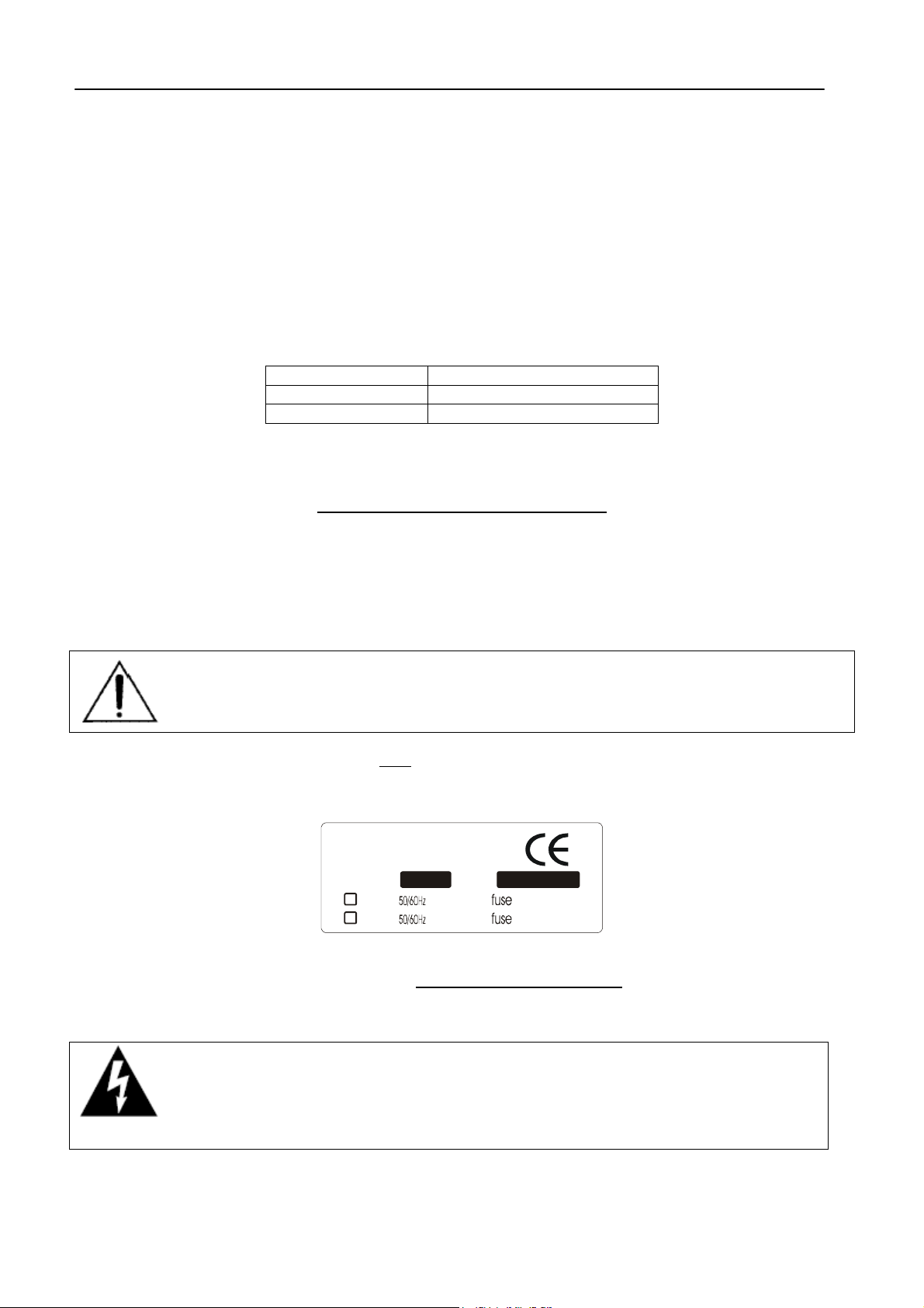
9.2 AC MAINS VOLTAGE SETTING (230 V / 115 V)
BE SURE THAT THE UNIT IS SET TO THE CORRECT M AINS/LINE VOLTAGE FOR YOUR
COUNTRY BEFORE PLUGGING IT INTO THE WALL OUTLET !
The actual Mains voltage is indicated on the label
the operation location not be known, please contact your dealer or electricity company.
stuck on the equipment closure. Should the type of power at
Manufacturer
Model :
230V
115V
If, for som e reas on, the unit is to be operated at a mains input voltage which is different to that as s upplied, you
need to open the top cover and set properly the voltage change-ov er switch
the transformer. You also need to replac e the AC main fuse, according to information provided on the ex ternal
label or on the Technical Specifications table at the end of this user manual.
CAUTION: TO REDUCE THE RISK OF ELECTRICAL SHOCK, ALWAYS DISCONNECT
THE AC MAINS CABLE BEF ORE ALTERING THE CHANGE-OVER SWITCH. NO USER
SERVICEABLE PARTS INSIDE. REFER SERVICING TO QUALIFIED SERVICE
PERSONNEL.
XX
VA
VA
S-N :
KKKK
mAT
mAT
which is located inside, close to
Page 14
Page 15
FIRST INSTALLATION RECOMMENDATIONS ENG
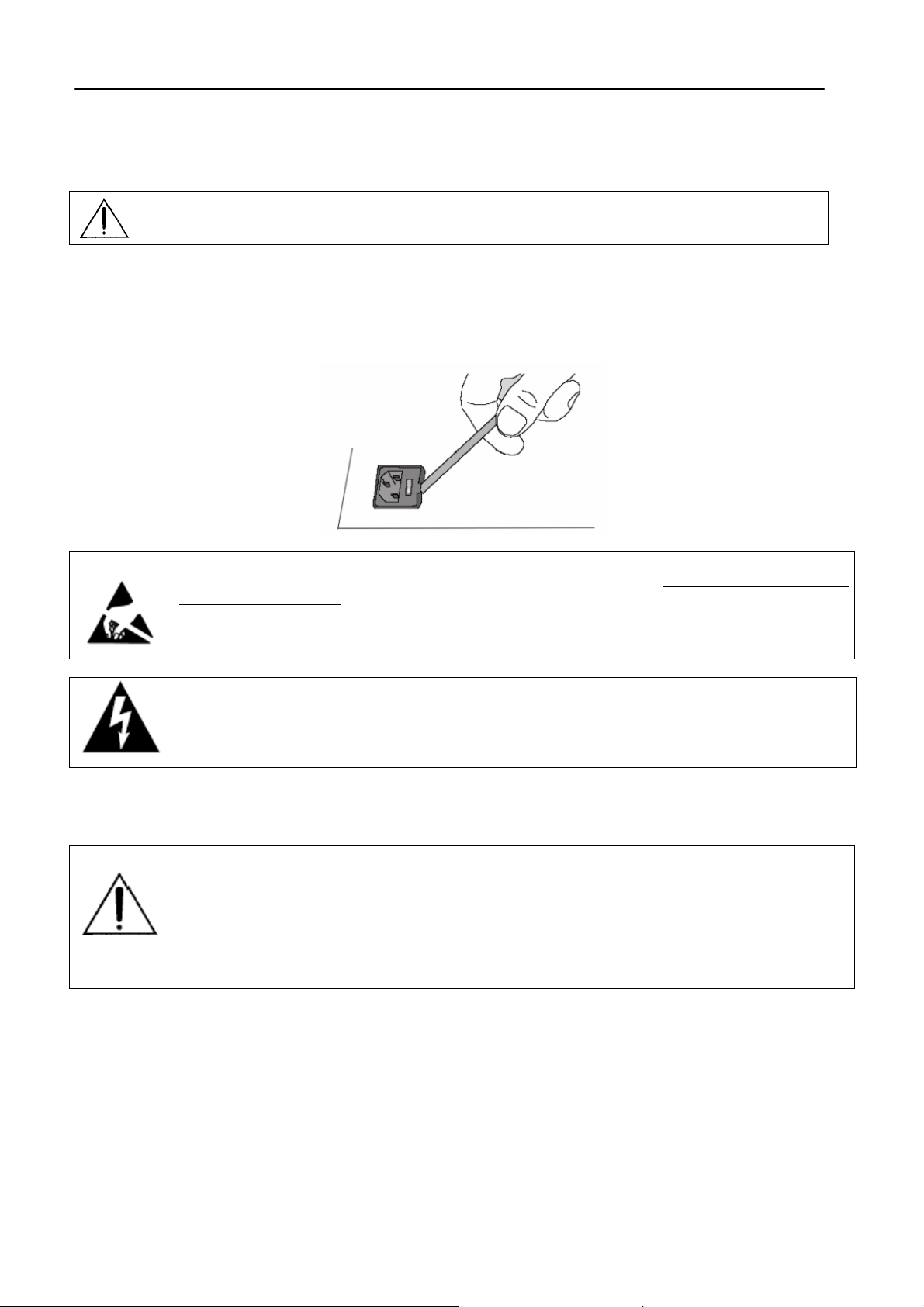
9.3 FUSE REPLACEMENT
The power supply socket has an integral fuse drawer containing the AC power fuse and a spare, both of the
same value.
BEFORE REPLACING T HE POWER FUSE, MAKE SURE YOU HAVE T HE RIGHT TYPE OF
FUSE FOR THE VOLTAGE TO BE PROTECTED.
USING WRONG FUSE TYPE WILL RESULT IN INSUFFICIENT PROTECTION.
Make sure that the power is switched off and the power cable is disconnected from the equipment.
Open the fuse drawer using a small blade screwdriver.
Replace the fuse located at the inner position
Push the fuse socket back into the original position
9.4 PROTECTION AGAINST LIGHTNING
Perform the set- up under static control conditions. Static charges are likely to com pletely destroy
one or more of the CMOS semiconductors employed in the unit. Static damage will not be
covered under warranty.
Basic damage prevention consis ts of minimizing generation, discharging any accumulated static
charge on your body and preventing that discharge fr om being sent to or through any electronic
component.
Uninsulated dangerous voltage are inside the enclosure, voltage that may be sufficient to
constitute a risk of shock.
Always disconnect to AC Mains before removing the top cover
Should the device be put out of action due to being struck by lightning or excess voltage,
disconnect it from the power supply without delay. Do not reconnect until the device has been
checked. If in doubt contact the technical support service.
Make sure there is suitable lightning protection to protect the device.
Alternatively you should disconnect all connectors from the device during a storm or when the
device is going to be unsupervised or not used for a longer period of time.
These measures will protect against damage by lightning or excess voltage.
9.5 VENTILATION
The equipment will operate as a free-standing unit without requiring any special cooling arrangement.
However, slots and openings in the product are provided for ventilation. They ensure reliable operation of the
product, keeping it from overheating. These openings must not be blocked nor covered during operation.
YOU MUST LEAVE AT A MINIMUM ONE RACK UNIT OF EMPTY SPACE ABOVE THE EQUIPMENT TO
ENHANCE VENTILATION AND TO GET A LONGER EQUIPMENT LIFE.
Page 15
Page 16

BLOCK DIAGRAM (FM & ST VERSIONS) ENG
control
10 BLOCK DIAGRAM (FM & ST VERSIONS)
AUX
AUX
1
NPU
T
I
Output Level
2
O
UTPUT
NPU
T
I
O
G
L
UTPUT
Analog Output
Versio n Only
M
ANA
P
X
O
O
UTPUT
Versio n Only
MPX
MPX+RDS
digital
24 bi t
D/A
coder
clock
6th Or der
15KHz
Elliptic
II R LP
O
G
ANA
D
TAL
IGI
NPU
T
I
receiver
32,44.1,48,96
AES3
KHz
lo w jitter
PLL
converter
24 bi t
system
rate
clock
digital
AGC
control
RMS
L
NPU
T
I
AGC
±20dB
105 dB dynamic
24 bi t
A/D
range
system
Butterworth
2 nd Order
HP
true
Output
Select
Split Control
oscillator
38KHz
digital
clipper L
MPX
digital coder MPX+RDS
Generator
To n e
transform
clipper
Hilbert
8th Ord e r
15KHz
Elliptic
II R LP
Generator
Generator
clipper R
MPX
Level
RDS
Pilot
Level
Phase
Out
RDS
Pilot
Pilot
Sync
Broadband
limiter
density
gain
Butterworth
2 nd Order
IIR LP
400
Hz
compressor
Bass
coupling
50uS/75uS
emphasis
pre
5K -15K
Butterworth
Butterwor th
400 -5
4th Ord e r
IIR BP
Hz KHz
compressor
Mid
4th Or der
IIR BP
Hz Hz
compressor
High
Logaritmic
Amplifier
Limiter
oversampler
X8
Input L
oversampler
X8
Inpu t R
Bass
Cancell ing
Distortion
Filter
Logaritmic
Amplifier
Denoiser
Page 16
Page 17
FM VERSION DESCRIPTION ENG
11 FM VERSION DESCRIPTION
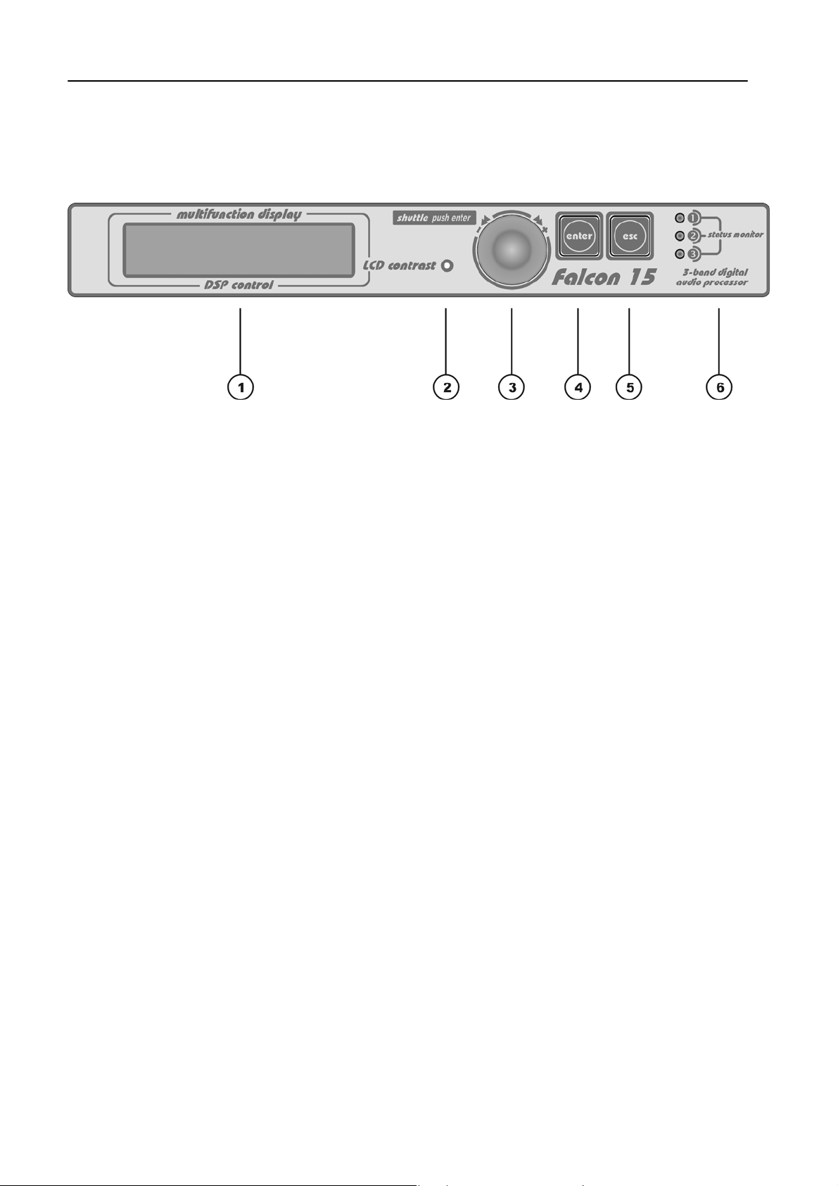
11.1 FRONT PANEL VIEW
1
Multifunction display (LCD) multifunction display showing the equipment operating conditions
2
LCD contrast: trimmer to adjust the display contrast. Please use a small screwdriver
3
Jog-wheel: for menu scrolling and parameter settings. It can also be pressed, having the same
control function as the Enter key
ENTER: key to access to the parameters submenu and to select the new values
4
Esc: key to Esc the current menu and go back to the previous one. By pressing this key the
5
modifications realised by accident on the selected parameter are not executed
LEDS: they show external inputs status (related to M/S and TA RDS status and to Split Enabling):
6
The three LEDs on the front panel light as the following:
LED 1
LED 2
LED 3
This LED lights up while Input 1 on Digital Data Port is ‘active’ - Split Mode enabled (please refer
to Section 12.5)
This LED lights up while Input 2 on Digital data is ‘active’. Input 2 is related to M/S RDS switch
(please refer to par. 18.5)
This LED lights up while Input 3 on Digital data is ‘active’. Input 3 is related to TA RDS switch
(please refer to par. 18.5)
Page 17
Page 18
FM VERSION DESCRIPTION ENG
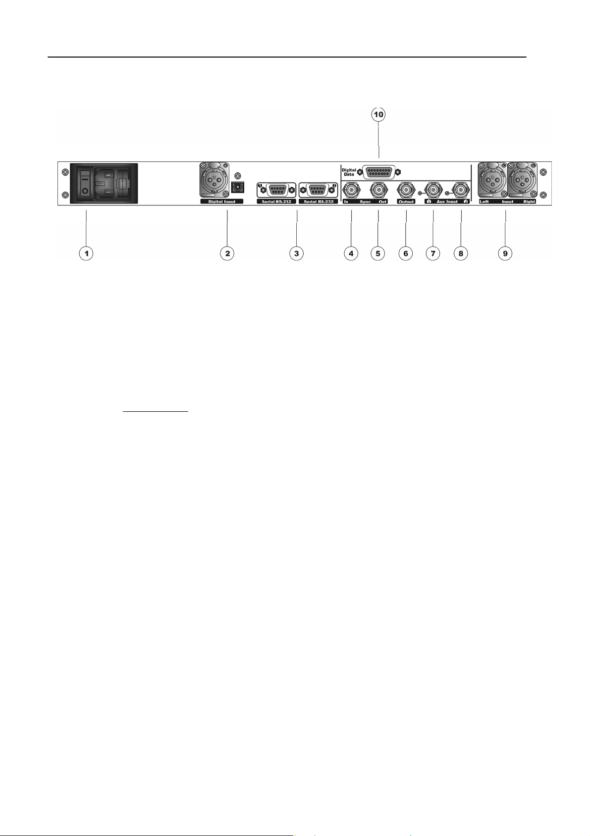
11.2 REAR PANEL VIEW (FM VERSION)
ON/OFF main switch, the led inside switchs on/off accordingly. If it is off while the switch is ON, please
1
check the supplied AC cord and the fuse.
AC outlet: IEC power cord receptacle. AC voltage change-over switch is located inside the box, closed to
the AC transformer
Digital input*. It features two connectors: XLR female for coaxial connections and tos-link for optical
2
connections
RS232 Serial Ports: optoisolated serial ports for connection to PCs or satellite receivers.
3
Sync-in (not connected)
4
Sync-out: Synchronism output. It provides 19KHz tone at 5Vpp to lock external equipment (for instance
5
RDS coders)
Out It features Stereo Composite signal or Stereo Composite signal +RDS (with or without signals
6
injected from Aux 1 and 2 mixed into). The output is set for a 75 Ohm load
Multipurpose Aux In (for external RDS, SCA, etc..): the injected signal is adjusted by the related
7
trimmer (near to the Bnc), mixed to the Falcon 15 internally generated signal and output by the main Out
connector. Factory preset: 0 dB gain
Multipurpose Aux In (for external RDS, SCA, etc..): the injected signal is adjusted by the related
8
trimmer (near to the Bnc), mixed to the Falcon 15 internally generated signal and output by the main Out
connector. Factory preset: 0 dB gain
Analog Input: bi-channel audio input electronically balanced on XLR female. The input level is set via the
9
menu
Digital Data Port: SubD 15-pin female Interface. It provides 3 optoinsulated “trigger” inputs (for RDS M/S
10
and TA service enabling and for splitting mode control)
* available as an option (DG-IN option – ref to Chapter 2)
Page 18
Page 19
FM VERSION DESCRIPTION ENG
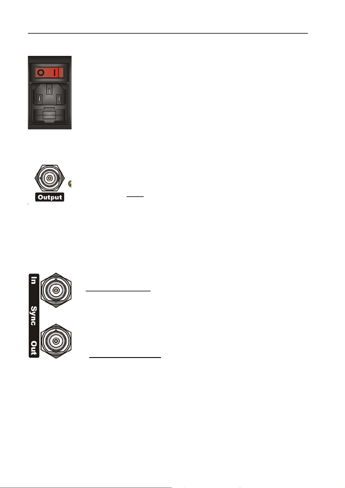
11.3 AC CONNECTION
The Falcon 15 uses a power entry module with AC switch just clos ed to the IEC power
cord receptacle. It can operate on 110 or 240 VAC, 50/60 Hz AC mains voltages. If the unit
is to be used with a mains voltage differ ent to that for which the unit is supplied, set the
voltage change-over switch, which is placed inside the box, closed to the AC transformer.
The power supply socket has an integr al fuse drawer containing the AC power fus e and a
spare, both of the same value.
- for 220/230 V AC the fuse is rated at 500 mA T
- for 110/115 V AC tension the fuse is rated at 1 A T
11.4 OUTPUT CONNECTOR
Depending on the version, Output BNC connector (50 Ohm im pedance) features Stereo
Composite Signal (MPX) and/or RDS s ignal (with or without signals injected from Aux 1
and 2 mixed into).
You can adjust the overall
MODULE SETUP page) in the – 9 dBm to +15dBm range. Factory preset: 0 dBm (2.2
Vpp).
Output connector can provide a refer ence tone consisting of a 500 Hz / 0 dBm sinusoidal
signal. This tone corresponds to the maximum frequency deviation. To enable it, see par.
12.3.3 .
11.5 SYNC-IN AND SYNC-OUT CONNECTORS
Sync In:
It is disconnected (not used)
Sync Out
This TT L-level (5Vpp) 19 k Hz square wave output can be used as the re ference s ignal for
any SCA generator that operates at 57 kHz or other multiple of the 19 kHz pilot frequency.
Using the 19 kHz clock from the Falcon 15 makes it much easier to phase lock the
external signal to the pilot frequency. This is extremely helpful in order to remove
intermodulation
The Sync Output is disabled
enabling).
components. For RDS coders, this feature is also very useful.
output level through the menu (MPX Level control in the MPX
by default (see par. Output Sync menu 12.3.5 for
Page 19
Page 20
FM VERSION DESCRIPTION ENG
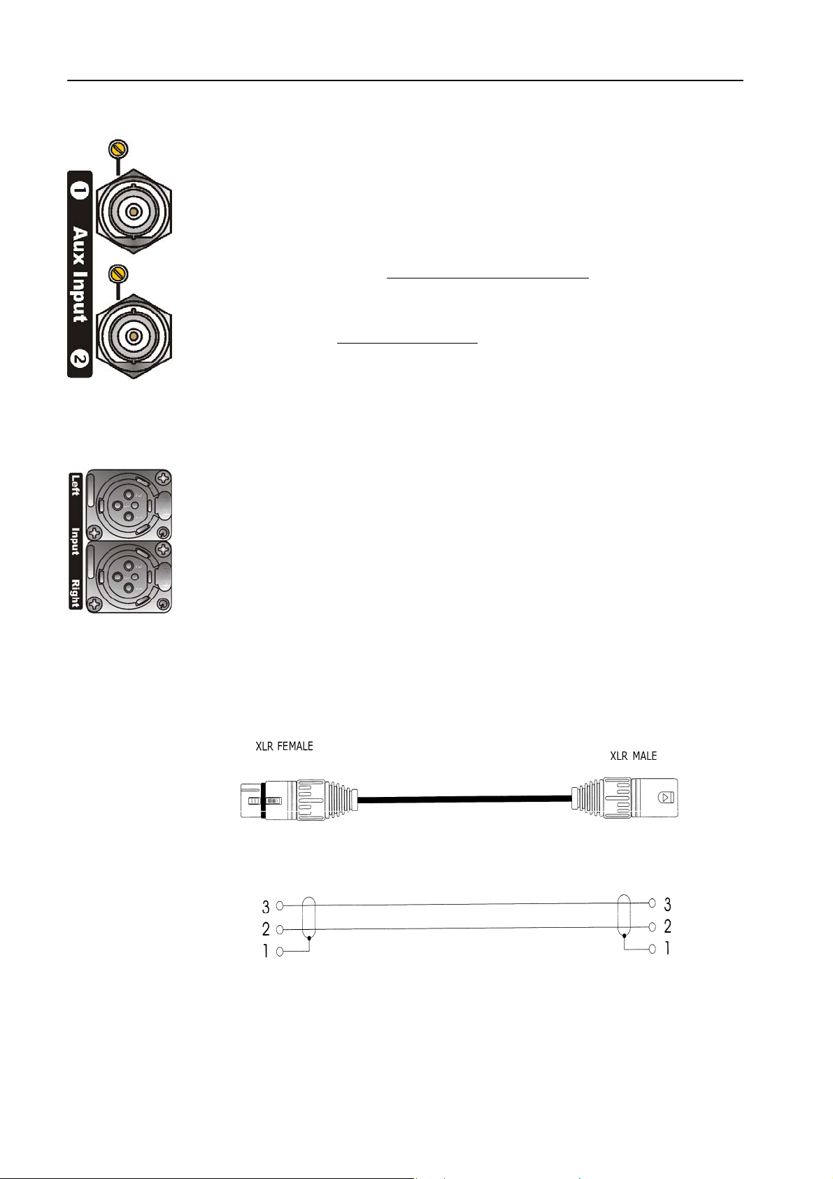
11.6 AUXILIARY INPUTS
The Aux inputs allow the Mpx, SCA, RDS injection from external coders. The resultant
signal (f.i. external RDS+ self-generated MPX) is available on the Output connector.
Remarks:
When using an external RDS encoder, the internal RDS one must be disabled.
The level of the injected signal may be adjusted by means of the trimmer next to the
corresponding BNC connector (no software control is provided
trimmer is factory preset for a gain of 0 dB.
Suggested RDS injection level is -31.5 dBm (≈ 60mVpp / 2.0 kHz deviation) in relation to
an MPX output of 0 dBm (2.2 Vpp, 0.776 Vrms).
AUX Input impedance is 10 KOhm.
11.7 ANALOG AUDIO INPUT (Female XLR)
Balanced XLR-type connectors are used for input analog audio.
The stereo analog inputs are designed for standard 0 dBu balanced signals. Input level
setting (Sensibility) is done using the software parameter settings (see par. 12.1).
XLR pinout:
In case of unbalanced connections, pleas e connec t the c old pole (Pin 3) to the ground ( Pin
1).
Factory preset input impedance is 10 kOhm . This im pedance m ay also be set to 600Ohm
by moving the two internal jumpers on the INPUT board (see Chapter 19 - hardware
settings).
Pin 1 Gnd
Pin 2 Signal
Pin 3 Return
for this purpose). This
Page 20
Page 21
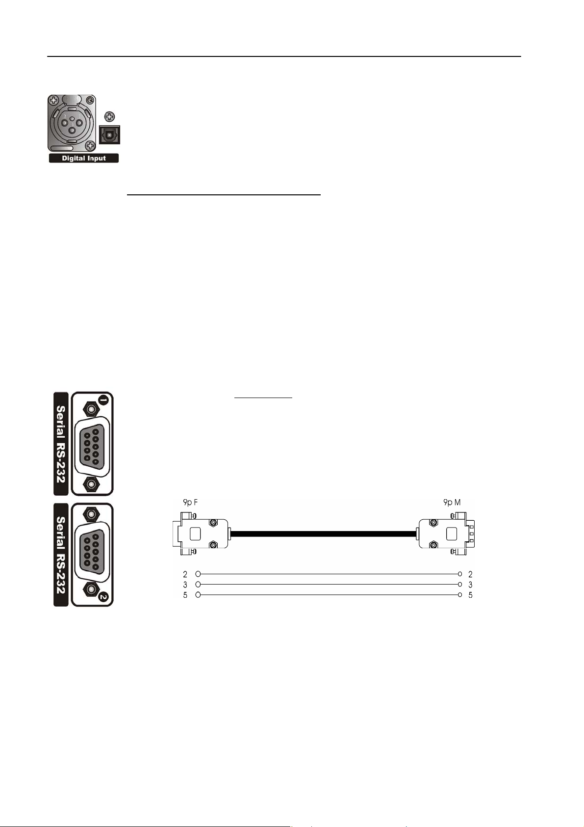
11.8 DIGITAL AUDIO INPUT
Transformer balanced XLR-type and optic connectors are used to input AES-3, S/PDIF,
IEC60958, EIAJCP1201 digital audio.
To avoid malfunctions, only one digital connector may be connected at a time. Please keep
the tos-link connector covered while not used.
The digital input accepts any sampling rate between 32 and 96 kHz. No user adjustment is
necessary since a sam ple rate converter is built into the unit. Furthermore, digital input
automatically recognizes the digital format
connection (optic or coaxial).
Even though both analog and digital input audio cables can be connected, only one input
can be set active (analog/digital input selection is done through the software parameter
setting - par. 12.1). Input gain and level setting for digital input is fixed.
XLR pinout: Pin 1 Gnd
In case of unbalanc ed c onnections (as r equired by S/PDIF form at), s hortcut pin 3 and 1 or
connect the unbalanced signal to XLR Pin 2 (hot) and Pin 3 (Gnd).
11.9 SERIAL PORTS
Falcon 15 features two optoinsulated RS232 serial ports which allow the remote control
and RDS programming via a connected PC (ref to Chapter 16).
Connect a standard serial cable (not cros sed) between the RS-232 connector and a serial
port connector on the computer. Cable length must not exceed 10 mt.
The ports can be separately enabled / disabled via the menu (see par. 12.6.1).
The two serial ports support Tx and Rx signals only. One serial cable comes with the unit.
FM VERSION DESCRIPTION ENG
(AES, EBU, SPDIF, etc.) and the type of
Pin 2 Signal
Pin 3 Return
Page 21
Page 22
FM VERSION DESCRIPTION ENG
These inputs can be used to dynamic ally alter two RDS flags (TA and M/S) and to enable
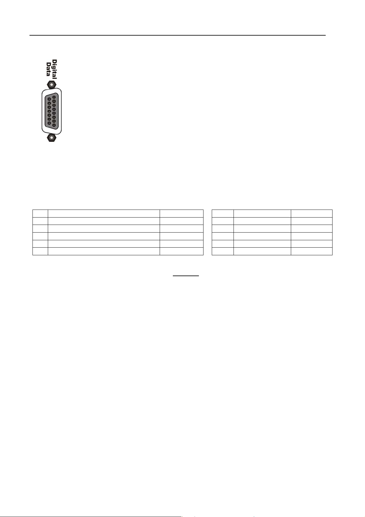
11.10 DIGITAL DATA PORT
15-pin female Interface connector provides 3 optoinsulated “trigger” inputs.
Split operating mode in response to logic signal transitions.
INPUT 1 is used to carry external network ‘split’ command (ref to Section 13).
INPUT 2 is used to dynamically alter M/S RDS flag. Input enabling will cause LED 2 on
Front Panel to light.
INPUT 3 is used to dynamically alter TA RDS flag. Input enabling enabling will cause LED
3 on Front Panel to light.
The following table displays internal connection of Digital Port and how to provide ( f .i.) an ex ter nal T TL command
to Input # 1.
PIN
1
Cathode of photocoupler input 1 (split)
2
Cathode of photocoupler input 2 (M/S)
3
Cathode of photocoupler input 3 (TA)
6
Anode of photocoupler input 1 (split)
7
Anode of photocoupler input 2 (M/S)
8
Anode of photocoupler input 3 (TA)
Pins 9, 10, 11, 12 are linked together and provide an insulated
A current-limited + Vdc source is available on pin 15 (+ 12 V via a 1K2 resistor).
DESCRIPTION DIRECTION PIN DESCRIPTION DIRECTION
IN 9 GND /
IN 10 GND /
IN 11 GND /
IN 12 GND /
IN 15 + Vcc OUT
IN
GND connection.
Page 22
Page 23
FM VERSION DESCRIPTION ENG
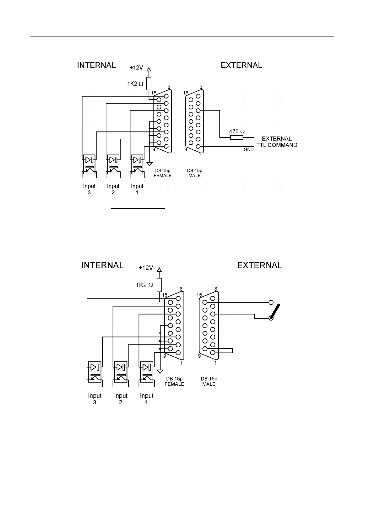
EXAMPLE N° 1 – controlling the SPLIT function from a TTL command
Apply an external TTL signal through a 470 Ohm
allowed: 10 mA. Nominal: 5 mA
carbon resistor to the photodiode 1 (pins 6 and 1). Max current
EXAMPLE N° 2 – controlling the SPLIT function from a clean contact
shortcut pin 9 and 1 and shortcut pin 15 and pin 6 via an external switch.
Page 23
Page 24

FM VERSION DESCRIPTION ENG
11.11 THE MENU TREE
The menu tree for the Falcon 15 M PX Version is shown on here below. It has all of the possible main menu
items listed along the left side.
The branching sub-menus and parameters are connected in the order they are encountered in the menu system.
The diagram here below displays the com plete
feature list.
|-|--
|- |--
|--
MAIN PAGE (Preset, Agc level, Compressor levels, Input Meters)
Input Setup
-- |--
Sensibilty
AGC Speed
AGC Mode
Input Source
Mpx Module Setup
|--
-- |--
|- |--
|- |- |- |--
Rds Setup
|--
-- |--
|- |--
Serials Setup
|--
-- |--
|--
System Information
|--
|--
-- |--
|--
|--
Pilot Level
Pilot Phase
Preemphasis
Output (Mpx) Level
|--
Output Mode
Mpx mode
Output Sync
Noise Gate
Rds Encoder
Rds Level
Rds On Split
Serial Port 1
Serial Port 2
Temperature
External Inputs
Firmware Version
Firmware Code
Falcon 15 menu – please refer to the table on Cap. 2 f or O ptional
- 12 dBm to+ 12 dBm (1 dB step)
--
0 to 6 dB/sec (0.2 dB step)
--
Hold=0 sec & MaxG= 08 dB;
--
Hold=1 sec & MaxG= 10 dB;
--
Hold=0 sec & MaxG= 12 dB;
--
Hold=2 sec & MaxG= 12 dB;
--
Hold=3 sec & MaxG= 15 dB;
--
Hold=3 sec & MaxG= 20 dB;
--
Hold=0 sec & MaxG= 15 dB;
--
Hold=0 sec & MaxG= 20 dB;
--
Analogic / Digital input
--
Off / - 25 dB to – 15.5 dB (0.1 dB step)
--
- 12 Deg to + 12 Deg (1 Deg step)
--
50 uSec / 75 uSec (Internal)
--
- 9.0 dB to + 15 dB (0.1 dB step)
--
Normal / Peak Ref Tone / Split mode / Bypass
--
Normal (Stereo) / Mono (Left Input) / Mono (L+R)
--
Output Sync Disabled / Enabled
--
Off, - 80 dB to – 51 dB (1 dB step)
--
Rds Encoder Off / Rds Encoder On
--
- 44.0 dB to – 20.0 dB (0.1 dB step)
Rds Encoder Off / Rds Encoder On
--
Serial Disabled / Serial Enabled
--
Serial Disabled / Serial Enabled
--
Bit M/S On (1) / Off (0); bit TA On (1) / Off (0); Split On
--
(1) / Off (0)
Page 24
Page 25

FM VERSION DESCRIPTION ENG
11.12 FRONT PANEL OPERATION
As described at par . 11.1, Falcon 15 us er interf ace c onsists of a f ront panel-m ounted j og-wheel, two buttons and
an LCD screen. T he LCD screen displays menus, parameter settings and several bar graphs (Level Meters or
processing activity).
The menus are used for the processing parameters adjustement.
Rotating the jog-wheel lets You browse up or down through menus and parameter choices.
Pressing the jog-wheel (called “click ing”) selects the blink ing menu item or parameter choice. W hen editing the
parameter values, rotating the jog-wheel adjusts the parameter’s value up (by rotating CW) or down (CCW).
Once the desired value is reached, clicking the jog- wheel twice saves the value and returns the display to the
upper menu level. You can return to the upper m enu without saving by pressing the Esc key or by choosing the
‘Esc’ option.
Thus pressing (or click ing) the j og-wheel serves, depending upon the LCD screen status, as an Enter, Select or
Return command.
Please note that when a new value is only displayed – even blinking – it is immediately loaded into the equipment
processing so that the user can get a real time response.
Enter function is achieved by pressing ‘Enter’ button, too.
Esc/Return function is achieved by pressing ‘Esc’ button, too.
It is useful to remark that you can access all the menu settings and parameters also in a faster and more
confortable way trough the supplied PC control software, which allows an easy and effective remote monitoring
and control, too. W hen the Falcon 15 control is taken by the PC application in a bidirectional mode (see Chapt.
17), any access to the menu via the front panel keys is not allowed and the message “Remote Pc Host in
Control” is displayed.
NOTE: The front panel menu allows only RDS signal level and status setting. RDS / RBDS messages
programming and all the other related facilities requires the supplied Pc control software – see Chapter 16.
In order to prevent any modification to the Processor configurations, the Front Panel keyboard may be locked
(‘Lock’ procedure is available via the Pc software ).
To save the changes, firstly press Enter to get the Save function and then a second time to confirm
Press Esc to escape the menu without saving and get the upper menu level
Press Esc to get the upper menu level.
Page 25
Page 26

IN & OUT SETTINGS (FM VERSION) ENG
12 IN & OUT SETTINGS (FM VERSION)
Once the unit is installed, here’s the procedure to get your Falcon 15 operating properly using factory
presets. With proper calibration the Falcon 15 will give you the most accurate results for peak control
and modulation. Take the time to go through the steps laid out in this chapter!
12.1 HOW TO CONFIGURE THE INPUT (INPUT SETUP)
12.1.1 SELECTING THE INPUT (ANALOG OR DIGITAL)
Falcon 15 features, as an option, a digital audio input (ref to Section 0). The Input Setup / Input Source menu
switches between the analog and digital audio inputs.
12.1.2 ADJUSTING THE INPUT AUDIO LEVEL
The Input Setup / Sensibility menu controls the amount of gain or attenuation applied to the analog
To take full advantage of the processor potential, the AGC value should operate in compression mode
(meaning that it slightly reduces the input level). This is indicated on the display by a negative sign, while a
positive sign means there has been an expansion or gain increas e. The m es sage 'Gated' appear s on the display
to indicate that there is no incoming signal, or the signal is below the minimum AGC threshold.
Using a song or announcement rec orded at a standard level, adjust the Sensibility** parameter
Setup menu until the AGC value shown on the display (AGC:) ranges at - 2 / - 3 dB
If the Input Sensibility c ontrol is not enough to achieve the AGC condition described above, adjust the output
levels of the audio source dir ectly (mixers , PC audio cards, etc .). If neces sary, it may be acceptable to work with
AGC levels between -3 /- 4 dB and +3 / +4 dB.
- the digital input audio level is fixed
- the audio level indicated on the input level meters will reflect the current input mode setting
- when enabled, the digital input disconnects the analog one
audio input.
in the Input
.
** this control allows you to adjust the input signal amplification factor, to ensure a standard signal of 0 dB to the internal
processor circuits. For example: with a signal of 0dB, the Input Sensibility
Input Sensibility
To make sure that the Input Sensibility
dB.
The AGC numeric indic ation will indicate the audio level AFTER the INPUT GAIN has been applied, so you can
monitor the amount of input gain needed.
should be set to -4 dB.
is properly adjusted, make sure that the AGC indicator display averages around 0 / -2
should be set to 0dB; with a signal of +4dB, the
Page 26
Page 27

IN & OUT SETTINGS (FM VERSION) ENG
12.1.3 CHOOSING THE PROPER AGC OPERATION
One of the most important processor function is the Automatic Gain Control (AGC) system, which
compensates for variations in the input level to keep the signal at 0 dB.
The following parameters regulate the AGC function and may be edited:
- AGC Mode: acts on both the digital and analog inputs sets the maximum amplif ication level applied to the
input signal by the AGC (MaxG) and the correction waiting time (Hold)
- AGC Speed: acts on both the digital and analog inputs and sets the compensation speed of the input
channel signal level variation.
AGC Mode parameter mainly serves to regulate the m aximum level gain recoverable by the AGC (MaxGain) and
its intervention time ( Hold). Hold = 0 m eans that the s ystem reac ts instantly to any source signal variations, while
Hold = 2 means that you must wait two seconds before the automatic level compensation process begins.
For instance, setting MaxGain = 12 means that maximum amplification is +12dB: thus a -12dB signal can be
compensated to 0, while a -15dB signal will reach a maximum of -3dB.
F.i., if AGC Speed is set as 2 dB/sec and the input signal drops down of 6 dB, the compensation trip will be
completely reached after 3 seconds if Hold time is 0 s ec (6/2) and after 6 seconds (3 + 6/2) if Hold time is 3
seconds.
We sugges t setting a m edium MaxGain
be enough to alter level ratios between diff er ent musical passages, as in the case of clas sic al music), and Hold =
0 if the music flow is dis continuous and immediate AGC inter vention is required, or a higher Hold value (3 or 4
seconds) if any silent breaks may occur during the broadcast (pauses in speech, line changeover between
studios, etc.).
Falcon 15 menu provides 5 fixed co mbinations of MaxGain and Hold parameters (i.e. those parameters may
not be selected or edited individually, but only within preset combinations).
Mode 0 Hold=0Sec MaxG=+08dB
Mode 1 Hold=1Sec MaxG=+10dB
Mode 2 Hold=0Sec MaxG=+12dB
Mode 3 Hold=2Sec MaxG=+12dB
Mode 4 Hold=3Sec MaxG=+15dB
Mode 5 Hold=3Sec MaxG=+20dB
Mode 6 Hold=0Sec MaxG=+15dB
Mode 7 Hold=0Sec MaxG=+20dB
The AGC speed indicates the number of dB by which the input level may be increased or decreased in one
second.
For example, with AGC speed = + 5 dB, an input signal of – 15 dB will be reduced to – 5 dB in exactly two
seconds***
***the approach to the 0 threshold is slower, as AGC works at 1/4 of the user-set speed within the interval –3 to + 3 dB
centered on 0 dB reference level
High AGC Speed values obvious ly make it possible to quic kly recover strong level differ ences, but they can also
lead to unpleasant 'pumping' effects.
value (no more than +12 dB, keeping in mind that this value may already
Page 27
Page 28

IN & OUT SETTINGS (FM VERSION) ENG
We sugges t using medium levels of around 2 to 3 dB / sec, and especially that you concentrate on the audio
sources connected to the processor, to obtain the most even sound possible.
12.2 THE VOICE OPTIMIZER
NOTE: The processor features a phase rotator input stage, also called ‘Voice Optimizer’ that is always kept
active.
It is a special all-pass filter designed to pr operly modify input s ignal wavefor m in order to avoid unpleasant effects
in the processing of ‘live speech’ material.
Typical speech waveforms (as those sourced by microphones) are mostly asymmetric, while typical ‘musical’
signals are symmetric.
As asymmetric clipped signals r esult in a more unpleasant ‘sound’ to the ear than the symmetric clipped ones, a
filter designed to convert asymmetric waverforms into symmetric waveforms is enabled by default, giving
significant improvements on speech processing and removing any distortion.
Page 28
Page 29

IN & OUT SETTINGS (FM VERSION) ENG
12.3 HOW TO CONFIGURE THE MPX OUTPUT (MPX MODULE SETUP)
12.3.1 SETTING THE PREEMPHASIS
The Mpx Module Setup / Preemphasis menu toggles between 50uS and 75uS of preemphasis applied to the
Falcon 15’s MPX output.
European countries use a 50 uSec preemphasis, while US countries use a 75 uSec preemphasis.
NOTE: FALCON 15 PREEMPHASIS REMAINS ACTIVE AT ALL TIMES AND CAN NOT BE
REMOVED FROM THE MPX OUTPUT
Only one pre-emphasis must be kept active in a transmitting chain. Turn always off the pre-emphasis generated
by transmitters.
NOTE: MAKE SURE YOU HAVE PREEMPHASIS SET TO THE APPROPRIATE VALUE FOR YOUR
APPLICATION BEFORE CALIBRATION AS THIS WILL AFFECT THE OUTPUT LEVEL
12.3.2 MONO - STEREO OPERATION
The MPX Module Setup / Mpx Mode menu selects the m ono versus stereo operation of the composite output.
With Mono audio modes enabled, Pilot tone is automatically turned off.
In particular:
Selecting Mono (Left) will remove the L-R portion of the composite signal and simply output the left
audio input. The Pilot will be turned off
Selecting Mono (Left+Right) will remove the L-R portion of the composite signal and simply output the
sum of the left and right audio inputs. The Pilot will be turned off
.
12.3.3 ADJUSTING THE MPX OUTPUT LEVEL
The MPX signal (+ any internally or externally generated RDS signal) is available on the Bnc MPX OUT
connector.
We recommend connecting the processor output directly to the transmitter or radio link, without inserting any
other equipment. The factory preset for the overall MPX signal is 0 dBm.
Where necessary, this output may be tuned using the Mpx Module Setup / Output Level menu.
In order to best adjus t the output level, we recom mend enabling a pilot tone
which should match the deviation of 75 KHz. To do this:
.
, which identifies the maxim um peak
Page 29
Page 30

IN & OUT SETTINGS (FM VERSION) ENG
1
Escape from the Output Level menu and enter the Output Mode menu.
2
Select the Peak Reference Tone option.
The Peak Tone identifies the maximum peak value of the audio and MPX signals reached by the processor while it is
operating. This peak corresponds to the maximum frequency deviation
chain simply and safely.
The Peak Tone consists of a 500 Hz/ 0 dBm tone + a 19 kHz / - 20 dB pilot tone
selecting the Off option within the MPX Module menu before enabling the Peak Reference Tone mode).
3 Once you have enabled the Peak Tone, adjust the Mpx Output Level until You reach the desired
modulation deviation.
4
Select the Normal Operation option in the Output Mode menu
(Normal Operation mode allows a normal use of the equipment and all its functions)
NOTE: THE PROCESSOR FACTORY SETTINGS ARE 0 dB FOR BOTH INPUT AND OUTPUT.
TO ACHIEVE THE BEST AUDIO QUALITY, WE RECOMMEND NOT TO LOWER THE OUTPUT
LEVEL AND TO ADJUST THE EQUIPMENT CONNECTED TO THE PROCESSOR (STEREO
ENCODERS, EXCITERS, ETC.) RATHER THAN THE PROCESSOR ITSELF.
12.3.4 CALIBRATING THE PILOT LEVEL AND PHASE
The Mpx Module / Pilot Level menu allows you to adjust the amount of 19kHz pilot tone injected into the
composite signal (expressed in dB). F actory-default value is – 20 dB (+/- 7.5 kHz carr ier deviation) com pared to
the overall Stereo Composite MPX signal. Level may be adjusted within the range of -25 dB to -15.5 dB, in 0.1 dB
steps. Pilot tone may also be disabled by turning the jog-wheel anti-clockwise to Off.
The Mpx Module / Pilot Phase menu allows you to adjust the phase relationship between the 19 kHz pilot and
the 38 kHz modulator. This c an be used to correct for inconsistencies am ong different transmitters. It may be
adjusted from -12.0 to + 12.0 degrees (Deg) in 1 deg steps
12.3.5 ENABLING SYNC OUTPUT
When required, Falcon 15 can supply TTL pilot s ynchro signal (19 kHz, square wave, 5 Vpp) on the Sync Out
connector.
To do this, enter the Mpx Module Setup / Output Sync menu and select Output Sync Enabled option.
. This allows you to set the levels for the entire sound
(the pilot signal may be disabled by
Page 30
Page 31

IN & OUT SETTINGS (FM VERSION) ENG
12.3.6 NOISE GATE SETTING (Noise Gate)
The Mpx Module Setup / Noise Gate function allows you to avoid the effect s of background noises while the
input signal presents a lack of high frequencies. The parameter to be set is the Noise Gate Th reshold, which
determines the threshold value below which the dynamic pre-emphasis is automatically excluded.
The Noise Gate Threshold: This may be adjusted within a range of –80 to –51dB (1 dB steps).
The Noise Gate function can be turned off if necessary by turning the shuttle counter-clockwise to the Off
position.
12.3.7 BYPASS MODE
In Processor ByPass mode, all the proc essing stages are disabled (AGC system, audio processing and pre-
emphasis circ uit). It allows you to carry out tests and ref erence measurem ents: it is not intended for equipment
setup or installation use
Page 31
Page 32

IN & OUT SETTINGS (FM VERSION) ENG
12.4 ADJUSTING THE RDS / RBDS OUTPUT (RDS MODULE SETUP)
The level of gener ated RDS / RBDS signal and its status On/O ff can be adjus ted by means of the RDS Module
Setup menu.
Selection of the Data System to be used (RDS or RBDS) can be achieved from the SETUP page in the Pc
Control Software page, after connecting to a processor featuring the RDS/RBDS encoder.
RDS Encoder menu allows You to turn the encoder On and Off.
The RDS signal Level may be adjusted within the deviation range. Here below are presented some relations
between deviation and RDS signal level:
-37.5 dB D=1.0 KHz
-31.5 dB D=2.0 KHz
-28 dB D=3.0 KHz
-25.5 dB D=4.0 KHz
-23.5 dB D=5.0 KHz
-21.9 dB D=6.0 KHz
- The default
- The RDS signal is available on the MPX Out connector, blended together with the MPX signal.
Also see Section 12.3.3 for setting the overall MPX signal
The RDS On Split option allow / don’t allow the Falcon 15’s RDS signal to be output in MPX splitted session.
** Falcon 15 with RDS option installed – Ref to Chapter 2.1
operating level is -31.5 dB, D = 2.0 KHz with an overall MPX level of 0 dBm
Page 32
Page 33

IN & OUT SETTINGS (FM VERSION) ENG
12.5 SETTING THE SPLIT MODES
The MPX SPLIT mode allows Falcon 15 Output to toggle between an external MPX signal applied to AUX 1 input
and the MPX signal internally generated (see Switch SW 1 and SW 2 her e below). Switching is triggered by Input
1 on Digital Data Port (ref to par. 11.10).
NOTE: FALCON 15 - FM VERSION IS REQUIRED, WITH INSTALLED SPLIT OPTION (ref to Chapt. 2)
MPX SPLIT
mode
SW 1 SW 3
enabled
Whenever the RDS option is also installed (ref to Section 2.1), RDS s ignal available on the Output with the
Split Mode activated depends on the ‘RDS On Split’ function setting (see Table here below). In other words, RDS
signal generated by Falcon 15 may be always available (even when the AUX signal is routed to the Output) or it
may be removed.
data port
INPUT1
active Internal Mpx open closed
unactive Fold-back of Aux 1 signal * closed open
OUTPUT LOGIC SWITCHERS
RDS ON
SPLIT mode
Sw1 Sw2 Sw3
disabled
enabled
data port
INPUT1
active Internal Mpx + internal RDS open closed closed
unactive Fold-back of Aux 1 signal * closed open open
active Internal Mpx + internal RDS open closed closed
unactive Fold-back of Aux 1 signal* + internal RDS
OUTPUT LOGIC SWITCHERS
closed closed open
* Aux 1 level is controlled via trimmer (ref to par. 11.6)
Page 33
Page 34

IN & OUT SETTINGS (FM VERSION) ENG
12.6 ADDITIONAL DATA AND SETTINGS
12.6.1 SERIAL PORT SETUP
Serial Port Setup displays the serial port 1 and Port 2 status and allows to enable/disable them.
- Serial Port 1
- Serial Port 2
12.6.2 SYSTEM INFO
The System Info page provides useful data concerning Falcon 15 operation:
- Temperature
- Ext Inputs It displays the current state of the three Digital Data inputs (see par. 11.10). IN=1 m eans
- FW Version
- FW Code
This selection allows you to enable / disable the port
This selection allows you to enable / disable the port
it shows the internal temperature of the processor during operation.
The current temperature is updated each time this option is accessed.
For proper operation, the temperature should never exceed 50 °C. If this threshold is
exceeded, you must
and below the processor.
active input, IN=0 means input disabled
It shows the current Falcon 15 firmware version. Firmware may be upgraded to later
versions (ref to Chapter 20.1)
It shows firmware serial code. The user might be requested to communicate it to the
manufacturer in some cases
leave a ventilation space equivalent to at least 1 rack unit both above
Page 34
Page 35

13 ST VERSION DESCRIPTION
13.1 FRONT PANEL VIEW
1
Multifunction display (LCD) multifunction display showing the equipment operating conditions
2
LCD contrast: trimmer to adjust the display contrast. Please use a small screwdriver
3
Jog-wheel: for menu scrolling and parameter settings. It can also be pressed, having the same
control function as the Enter key
ENTER: key which gives access to the parameters submenu and selects the new values
4
Esc: key to Esc the current menu and go back to the previous one. By pressing this key the
5
modifications realised by accident on the selected parameter are not executed
LEDS: disabled on the ST version
6
ST VERSION DESCRIPTION ENG
Page 35
Page 36

ST VERSION DESCRIPTION ENG
13.2 REAR PANEL VIEW (ST VERSION)
ON/OFF main switch, the led inside switchs on/off accordingly. If it is off while the switch is ON, please
1
check the supplied AC cord and the fuse.
AC outlet: IEC power cord receptacle. AC voltage change-over switch is located inside the box, closed to
the AC transformer
Digital input*. It features two connectors: XLR female for coaxial connections and tos-link for optical
2
connections
RS232 Serial Ports: optoisolated serial ports for connection to PCs or satellite receivers.
3
Analog Output: bi-channel audio output electronically balanced on XLR male connectors. The output
4
level is set via the menu
Analog Input: bi-channel audio input electronically balanced on XLR female. The input level is set via the
5
menu
* available as an option (DG-IN option – ref to Chapter 2)
Page 36
Page 37

13.3 AC CONNECTION
The Falcon 15 uses a power entry module with AC switch just clos ed to the IEC power
cord receptacle. It can operate on 110 or 240 VAC, 50/60 Hz AC mains voltages. If the unit
is to be used with a mains voltage differ ent to that for which the unit is supplied, set the
voltage change-over switch, which is placed inside the box, closed to the AC transformer.
The power supply socket has an integr al fuse drawer containing the AC power fus e and a
spare, both of the same value.
- for 220/230 V AC the fuse is rated at 500 mA T
- for 110/115 V AC tension the fuse is rated at 1 A T
13.4 DIGITAL AUDIO INPUT
Transformer balanced XLR-type and optic connectors are used to input AES-3, S/PDIF,
IEC60958, EIAJCP1201 digital audio.
To avoid malfunctions, only one digital connector may be connected at a time. Please keep
the tos-link connector covered while not used.
The digital input accepts any sampling rate between 32 and 96 kHz. No user adjustment is
necessary since a sam ple rate converter is built into the unit. Furthermore, digital input
automatically recognizes the digital format (AES, EBU, SPDIF, etc.) and the type of
connection (optic or coaxial).
Even though both analog and digital input audio cables can be connected, only one input
can be set active (analog/digital input selection is done through the software parameter
setting - par. 12.1). Input gain and level setting for digital input is fixed.
XLR pinout: Pin 1 Gnd
ST VERSION DESCRIPTION ENG
Pin 2 Signal
Pin 3 Return
Page 37
Page 38

13.5 SERIAL PORTS
Falcon 15 features up to four optoins ulated RS232 serial ports (port 3 and 4 are available
as an option) which allow the rem ote c ontrol and RDS pr ogr amming both through local - or
remote PCs, UECP programmer, etc.
In particular, these connectors ar e for a local bidirectional computer connection when the
BSN - Remote Control software is loaded onto a loc al c omputer. Connect a standard serial
cable (not crossed) between the RS-232 connector and a serial port connector on the
computer. Cable length must not exceed 10 mt.
The ports can be separately enabled / disabled via the menu. UECP protoc ol allows the
user to assign different proper ties, data speed, acces to comm ands, etc to every port (see
par. 12.6.1).
The four serial ports support Tx and Rx signals only. One serial cable comes with the unit.
ST VERSION DESCRIPTION ENG
13.6 ANALOG AUDIO OUTPUT (Male XLR)
Balanced XLR-type connectors are used for output analog audio.
The stereo analog outputs are designed f or standard 0 dBu (line- level) balanced signals.
Output level setting is done using the software parameter settings (see par. 14.3).
XLR pinout:
In case of unbalanced connections, pleas e connec t the c old pole (Pin 3) to the ground ( Pin
1).
The impedance is set to 600Ohm (electronically balanced).
Pin 1 Gnd
Pin 2 Signal
Pin 3 Return
Page 38
Page 39

ST VERSION DESCRIPTION ENG
13.7 ANALOG AUDIO INPUT (Female XLR)
Balanced XLR-type connectors are used for input analog audio.
The stereo analog inputs are designed for standard 0 dBu balanced signals. Individual
channel gain and level setting is done using the software parameter settings (see par.
12.1).
XLR pinout:
In case of unbalanced connections, pleas e connec t the c old pole (Pin 3) to the ground ( Pin
1).
Factory preset input impedance is 10 kOhm . This im pedance m ay also be set to 600Ohm
by moving the two internal jumpers on the INPUT / OUTPUT board (see Chapter 19 hardware settings).
Pin 1 Gnd
Pin 2 Signal
Pin 3 Return
Page 39
Page 40

ST VERSION DESCRIPTION ENG
13.8 FALCON 15 MENU TREE (ST version)
The menu tree for the Falcon 15 ST-OUT Version is shown on here below. It has all of the possible m ain m enu
items listed along the left side.
The branching sub-menus and parameters are connected in the order they are encountered in the menu system.
The diagram here below displays the com plete Falcon 15 m enu – pleas e ref er to the table on Cap. 2 f or Optional
feature list.
MAIN PAGE (Preset, Agc level, Compressor levels, Input Meters)
|--
Input Setup
|--
-- |- |- |--
|--
Sensibilty
AGC Speed
AGC Mode
Input Source
- 12 dBm to+ 12 dBm (1 dB step)
--
0 to 6 dB/sec (0.2 dB step)
--
Hold=0 sec & MaxG= 08 dB;
--
Hold=1 sec & MaxG= 10 dB;
Hold=0 sec & MaxG= 12 dB;
Hold=2 sec & MaxG= 12 dB;
Hold=3 sec & MaxG= 15 dB;
Hold=3 sec & MaxG= 20 dB;
Hold=0 sec & MaxG= 15 dB;
Hold=0 sec & MaxG= 20 dB;
Analogic / Digital input
--
|--
Audio Mod. Setup
-- |--
|--
|- |--
Rds Setup
|--
-- |--
Serials Setup
|--
-- |--
|--
System Information
|--
-- |--
|- |--
|--
Preemphasis
Output Level
Output Mode
Process mode
|--
Noise Gate
Not Installed
Serial Port 1
Serial Port 2
Temperature
External Inputs
Firmware Version
Firmware Code
50 uSec Internal / 75 uSec Internal / 50 uSec External
--
/ 75 uSec External
- 10 dB to + 14 dBm (0.5 dB step)
--
Normal / Peak Ref Tone / Bypass
--
Normal (Stereo) / Mono (Left Input) / Mono (L+R)
--
Off, - 80 dB to – 51 dB (1 dB step)
--
--
Disabled / Enabled
--
Disabled / Enabled
--
Not Installed
--
Page 40
Page 41

ST VERSION DESCRIPTION ENG
13.9 FRONT PANEL OPERATION
As described at par . 11.1, Falcon 15 us er interf ace c onsists of a f ront panel-m ounted j og-wheel, two buttons and
an LCD screen. T he LCD screen displays menus, parameter settings and several bar graphs (Level Meters or
processing activity).
The menus are used for the processing parameters adjustement.
Rotating the jog-wheel lets You browse up or down through menus and parameter choices.
Pressing the jog-wheel (called “click ing”) selects the blink ing menu item or parameter choice. W hen editing the
parameter values, rotating the jog-wheel adjusts the parameter’s value up (by rotating CW) or down (CCW).
Once the desired value is reached, clicking the jog- wheel twice saves the value and returns the display to the
upper menu level. You can return to the upper m enu without saving by pressing the Esc key or by choosing the
‘Esc’ option.
Thus pressing (or click ing) the j og-wheel serves, depending upon the LCD screen status, as an Enter, Select or
Return command.
Please note that when a new value is only displayed – even blinking – it is immediately loaded into the equipment
processing so that the user can get a real time response.
Enter function is achieved by pressing ‘Enter’ button, too.
Esc/Return function is achieved by pressing ‘Esc’ button, too.
It is useful to remark that you can access all the menu settings and parameters also in a faster and more
confortable way trough the supplied PC control software, which allows an easy and effective remote monitoring
and control, too. W hen the Falcon 15 control is taken by the PC application in a bidirectional mode (see Chapt.
17), any access to the menu via the front panel keys is not allowed and the message “Remote Pc Host in
Control” is displayed.
In order to prevent any modification to the Processor configurations, the Front Panel keyboard may be locked
(‘Lock’ procedure is available via the Pc software ).
To save the changes, firstly press Enter to get the Save function and then a second time to confirm
Press Esc to escape the menu without saving and get the upper menu level
Press Esc to get the upper menu level.
Page 41
Page 42

IN / OUT SETTINGS (ST version) ENG
14 IN / OUT SETTINGS (ST version)
Once the unit is installed, here’s the procedure to get your Falcon 15 operating properly using factory
presets. With proper calibration the Falcon 15 will give you the most accurate results for peak control
and modulation. Take the time to go through the steps laid out in this chapter!
14.1 HOW TO CONFIGURE THE INPUT (INPUT SETUP)
14.1.1 SELECTING THE INPUT (ANALOG OR DIGITAL)
Falcon 15 features, as an option, a digital audio input (ref to Section 0). The Input Setup / Input Source menu
switches between the analog and digital audio inputs.
NOTE - the digital input audio level is fixed
- the audio level indicated on the input level meters will reflect the current input mode setting
- when enabled, the digital input disconnects the analog one
14.1.2 ADJUSTING THE INPUT AUDIO LEVEL
The Input Setup / Sensibility menu controls the amount of gain or attenuation applied to the analog
To take full advantage of the processor potential, the AGC value should operate in compression mode
(meaning that it slightly reduces the input level). This is indicated on the display by a negative sign, while a
positive sign means there has been an expansion or gain increas e. The m es sage 'Gated' appear s on the display
to indicate that there is no incoming signal, or the signal is below the minimum AGC threshold.
Using a song or announcement rec orded at a standard level, adjust the Sensibility** parameter
Setup menu until the AGC value shown on the display (AGC:) ranges at - 2 / - 3 dB
If the Input Sensibility c ontrol is not enough to achieve the AGC condition described above, adjust the output
levels of the audio source dir ectly (mixers , PC audio cards, etc .). If neces sary, it may be acceptable to work with
AGC levels between –3 /- 4 dB and +3 / +4 dB.
.
audio input.
in the Input
** this control allows you to adjust the input signal amplification factor, to ensure a standard signal of 0 dB to the internal
processor circuits. For example: with a signal of 0dB, the Input Sensibility
Input Sensibility
To make sure that the Input Sensibility
dB.
The AGC numeric indic ation will indicate the audio level AFTER the INPUT GAIN has been applied, so you can
monitor the amount of input gain needed.
should be set to -4 dB.
is properly adjusted, make sure that the AGC indicator display averages around 0 / -2
should be set to 0dB; with a signal of +4dB, the
Page 42
Page 43

IN / OUT SETTINGS (ST version) ENG
14.1.3 CHOOSING THE PROPER AGC OPERATION
One of the most important processor function is the Automatic Gain Control (AGC) system, which
compensates for variations in the input level to keep the signal at 0 dB.
The following parameters regulate the AGC function and may be edited:
- AGC Mode: acts on both the digital and analog inputs sets the maximum amplif ication level applied to the
input signal by the AGC (MaxG) and the correction waiting time (Hold)
- AGC Speed: acts on both the digital and analog inputs and sets the compensation speed of the input
channel signal level variation.
AGC Mode parameter mainly serves to regulate the m aximum level gain recoverable by the AGC (MaxGain) and
its intervention time ( Hold). Hold = 0 m eans that the s ystem reac ts instantly to any source signal variations, while
Hold = 2 means that you must wait two seconds before the automatic level compensation process begins.
For instance, setting MaxGain = 12 means that maximum amplification is +12dB: thus a -12dB signal can be
compensated to 0, while a -15dB signal will reach a maximum of -3dB.
F.i., if AGC Speed is set as 2 dB/sec and the input signal drops down of 6 dB, the compensation trip will be
completely reached after 3 seconds if Hold time is 0 s ec (6/2) and after 6 seconds (3 + 6/2) if Hold time is 3
seconds.
We sugges t setting a m edium MaxGain
be enough to alter level ratios between diff er ent musical passages, as in the case of clas sic al music), and Hold =
0 if the music flow is dis continuous and immediate AGC inter vention is required, or a higher Hold value (3 or 4
seconds) if any silent breaks may occur during the broadcast (pauses in speech, line changeover between
studios, etc.).
Falcon 15 menu provides 5 fixed co mbinations of MaxGain and Hold parameters (i.e. those parameters may
not be selected or edited individually, but only within preset combinations).
Mode 0 Hold=0Sec MaxG=+08dB
Mode 1 Hold=1Sec MaxG=+10dB
Mode 2 Hold=0Sec MaxG=+12dB
Mode 3 Hold=2Sec MaxG=+12dB
Mode 4 Hold=3Sec MaxG=+15dB
Mode 5 Hold=3Sec MaxG=+20dB
Mode 6 Hold=0Sec MaxG=+15dB
Mode 7 Hold=0Sec MaxG=+20dB
The AGC speed indicates the number of dB by which the input level may be increased or decreased in one
second.
For example, with AGC speed = + 5 dB, an input signal of – 15 dB will be reduced to – 5 dB in exactly two
seconds***
***the approach to the 0 threshold is slower, as AGC works at 1/4 of the user-set speed within the interval –3 to + 3 dB
centered on 0 dB reference level
High AGC Speed values obvious ly make it possible to quic kly recover strong level differ ences, but they can also
lead to unpleasant 'pumping' effects.
value (no more than +12 dB, keeping in mind that this value may already
Page 43
Page 44

IN / OUT SETTINGS (ST version) ENG
We sugges t using medium levels of around 2 to 3 dB / sec, and especially that you concentrate on the audio
sources connected to the processor, to obtain the most even sound possible.
14.2 THE VOICE OPTIMIZER
NOTE: The processor features a phase rotator input stage, also called ‘Voice Optimizer’ that is always kept
active.
It is a special all-pass filter designed to pr operly modify input s ignal wavefor m in order to avoid unpleasant effects
in the processing of ‘live speech’ material.
Typical speech waveforms (as those sourced by microphones) are mostly asymmetric, while typical ‘musical’
signals are symmetric.
As asymmetric clipped signals r esult in a more unpleasant ‘sound’ to the ear than the symmetric clipped ones, a
filter designed to convert asymmetric waverforms into symmetric waveforms is enabled by default, giving
significant improvements on speech processing and removing any distortion.
Page 44
Page 45

IN / OUT SETTINGS (ST version) ENG
14.3 HOW TO CONFIGURE THE AUDIO OUTPUT (AUDIO MODULE SETUP)
14.3.1 SETTING THE PREEMPHASIS
The Audio Module Setup / Preemphasis menu allows You to select one of the following options:
- 50uSec Internal
- 75uSec Internal
- 50uSec External
- 75uSec External
European countries use a 50 uSec preemphasis, while US countries use a 75 uSec preemphasis.
pre-emphasis enabled
pre-emphasis enabled
pre-emphasis disabled on audio outputs (an external 50 usec preemph. must be applied)
pre-emphasis disabled on audio outputs (an external 75 usec preemph. must be applied)
The processor generates two types of pre-emphasis : dynamic and fixed. The form er may vary in relation to the
modulation peak, thereby considerably increasing the average modulation within the maximum deviation of
75KHz, while the latter is fixed at 50 or 75uSec depending on the country in which it is used. The latter may be
removed from the analog audio outputs if necessary, while the first is always present to ensure proper modulation
at all times.
ONLY ONE
IT IS HIGHLY RECOMMENDED TO USE THE PRE-EMPHASIS W ITHIN THE PROCESSOR AND
TURN OFF THE ONE GENERATED BY EXTERNAL TX OR MPX CODERS.
PRE-EMPHASIS MUST BE KEPT ACTIVE IN A TRANSMITTING CHAIN.
NOTE: MAKE SURE YOU HAVE PREEMPHASIS SET TO THE APPROPRIATE VALUE FOR YOUR
APPLICATION BEFORE CALIBRATION AS THIS WILL AFFECT THE OUTPUT LEVEL
on the processor audio outputs at 50 usec
on the processor audio outputs at 75 usec
Page 45
Page 46

IN / OUT SETTINGS (ST version) ENG
14.3.2 ADJUSTING THE AUDIO OUTPUT LEVEL
The processed audio signal is available on the XLR OUT connectors.
The factory preset for the output signal is 0 dBm.
Where necessary, this output may be tuned using the Audio Module S etup / Output Level menu.
In order to best adjust the output level, we recom mend enabling a pilot tone
which should match the deviation of 75 KHz. To do this:
1
Escape from the Output Level menu and enter the Output Mode menu.
2
Select the Peak Reference Tone option.
The Peak Tone identifies the maximum peak value of the audio reached by the processor while it is operating. This peak
corresponds to the maximum frequency deviation
safely.
The Peak Tone consists of a 500 Hz/ 0 dBm tone.
3
Once you have enabled the Peak Tone, adjust the Audio Output Level until You reach the desired
modulation deviation.
4
Select the Normal Operation option in the Output Mode menu
(Normal Operation mode allows a normal use of the equipment and all its functions)
. This allows you to set the levels for the entire sound chain simply and
NOTE: THE PROCESSOR FACTORY SETTINGS ARE 0 dB FOR BOTH INPUT AND OUTPUT.
TO ACHIEVE THE BEST AUDIO QUALITY, WE RECOMMEND NOT TO LOWER THE OUTPUT
LEVEL AND TO ADJUST THE EQUIPMENT CONNECTED TO THE PROCESSOR (STEREO
ENCODERS, EXCITERS, ETC.) RATHER THAN THE PROCESSOR ITSELF.
14.3.3 BYPASS MODE
In Processor ByPass mode (Audio Module Setup / Output Mode / Bypass Mode menu), all the processing
stages are disabled (AGC system, audio proc essing and pre-emphasis circuit). It allows you to carry out tests
and reference measurements: it is not intended for equipment setup or installation use
, which identifies the maximum peak
Page 46
Page 47

IN / OUT SETTINGS (ST version) ENG
14.3.4 MONO - STEREO OPERATION
The Audio Module Setup / Process Mode menu selects the mono versus stereo operation of the audio output.
In particular:
Selecting Mono (Left) the Left input channel only will be processed and output on both the L and R outputs.
Selecting Mono (Left+Right) the sum of the lef t and right audio inputs will be process ed and output on both
the L and R outputs.
14.3.5 NOISE GATE SETTING (Noise Gate)
The Audio Module Setup / Noise Gate function allows you to avoid the effects of backgr ound noises while the
input signal presents a lack of high frequencies. The parameter to be set is the Noise Gate Th reshold, which
determines the threshold value below which the dynamic pre-emphasis is automatically excluded.
The Noise Gate Threshold: This may be adjusted within a range of –80 to –51dB (1 dB steps).
The Noise Gate function can be turned off if necessary by turning the shuttle counter-clockwise to the Off
position.
Page 47
Page 48

IN / OUT SETTINGS (ST version) ENG
14.4 ADDITIONAL DATA AND SETTINGS
14.4.1 SERIAL PORT SETUP
Serial Port Setup displays the serial port 1 and Port 2 status and allows to enable/disable them.
- Serial Port 1
- Serial Port 2
14.4.2 SYSTEM INFO
The System Info page provides useful data concerning Falcon 15 operation:
- Temperature
- Ext Inputs It displays the current state of the three Digital Data inputs (see par. 11.10). IN=1 m eans
- FW Version
- FW Code
This selection allows you to enable / disable the port
This selection allows you to enable / disable the port
it shows the internal temperature of the processor during operation.
The current temperature is updated each time this option is accessed.
For proper operation, the temperature should never exceed 50 °C. If this threshold is
exceeded, you must
and below the processor.
active input, IN=0 means input disabled
It shows the current Falcon 15 firmware version. Firmware may be upgraded to later
versions (ref to Chapter 20.1)
It shows firmware serial code. The user might be requested to communicate it to the
manufacturer in some cases
leave a ventilation space equivalent to at least 1 rack unit both above
Page 48
Page 49

CHOOSING THE PROCESSING CURVE ENG
15 CHOOSING THE PROCESSING CURVE
15.1 INTRODUCTION
Once you have adjusted the input levels and reached the correct AGC level
processing curve.
There are 30 factory presets designed for various program m ing form ats. Chose one that approximately matches
your station’s format. If you are not sure, chose Preset # 25 and 26 to ac hieve best results for density, richness
and colour of the sound.
As shown in the table on the next page, there are 3 parameters involved in the audio processing. The curves may
be gather into groups: curves from 1 to 10 have a low density, curves from 11 to 20 have a medium density
and curves from 21 o 30 have a high density (i.e. they allow you to reach a high broadcasting sound level and
an average sound fidelity).
Furthermore, cur ves 1, 11 and 21 are totally ‘flat’: You may compare the different curves if desired, using these
curves as a reference.
NOTE - Contrary to the submenu paramet ers, a new curve becomes operative (thus is b roadcast) only
when it is selected
selection.
via encoder and then confirmed by the ENTER command within 10 seconds after
, you may move on to select the
Page 49
Page 50

CHOOSING THE PROCESSING CURVE ENG
15.2 THE FALCON 15 PRESET TABLE
PRESET BASS MID HIGH DENSITY TYPE
1 1 1 1 Low Flat
2 3 0 3 Low Pop
3 1 3 1 Low Live
4 3 1 1 Low Bass
5 3 3 1 Low Disco
6 1 3 3 Low Live
7 3 3 0 Low Disco
8 3 0 1 Low Bass
9 3 1 2 Low Pop
10 3 2 2 Low Bass
11 4 4 4 Mid Flat
12 6 3 6 Mid Pop
13 4 6 4 Mid Live
14 6 4 4 Mid Bass
15 6 6 4 Mid Disco
16 4 6 6 Mid Live
17 6 6 3 Mid Disco
18 6 3 4 Mid Bass
19 6 4 5 Mid Pop
20 6 5 5 Mid Bass
21 7 7 7 High Flat
22 9 6 9 High Pop
23 7 9 7 High Live
24 9 7 7 High Bass
25 9 9 7 High Disco
26 7 9 9 High Live
27 9 9 6 High Disco
28 9 6 7 High Bass
29 9 7 8 High Pop
30 9 8 8 High Bass
The Bass Level param eter adjusts the threshold level that trips the bass frequency compr essor, affecting the
frequency band up to 400 Hz
The Mid Level parameter adj usts the threshold level that trips the middle frequency compr essor, affecting the
frequency band from 400 Hz to 5 KHz
The High Level parameter adjusts the threshold level that trips the high frequency compressor, affecting the
frequency band from 5KHz to 15KHz
(see block diagram)
(see block diagram).
(see block diagram).
Page 50
Page 51

CHOOSING THE PROCESSING CURVE ENG
15.3 CHOOSING A CURVE
As already explained in other sections of the manual, the DSPs in the proces sor implem ent three compres sors,
which affect the 3 bands: Bass, Mid and High.
The three meter bars displayed on the front panel indicate the level of compression exerted on each frequency
(in other words, the m ore notches shown, the more the corresponding f requency is compressed, and thus the
less will be audible).
The curves are identified by three letters: B (i.e Bass), M (i.e. Medium) and H (i.e. High).
The higher the value of a band in respect of the others, the more the band will be present on the output.
Example
The curve 02 (B3M0H3) mainly contains Bass and High sound components, as the Medium frequencies are
compressed (as indicated by the ‘0’ index, in respect of B=3 and H=3).
On the other hand, the curve 07 (B3M3H0) contains strongly presence of Bass and Mid frequencies, as High
frequencies are compressed (H=0).
As You can get from the preset table, curves 1, 11, 21; 2, 12, 22; 3, 13, 23, etc have the same ‘ratio’
between Bass, Medium and High frequencies (f.i. Bass level is twice the amount of Medium level, etc) but
the ‘absolute’ level index is higher, meaning that curve’s density is higher.
Example
The curve 12 ( B6M3H6) presents the same relation between the band levels (i.e.the ‘sound equalization’ is the
same than curve 02) but density has changed: as ‘absolute’ level index are higher than curve 02 (B6 > B3,
M3>M0, etc), curve 12 allows you to reach a higher broadcasting sound level
The preset table provides also, in the last c olumn, an useful classification of curves according to their ‘sound’
(pop, bass, disco, etc).
:
:
Page 51
Page 52

THE REMOTE PC CONTROL SOFTWARE ENG
16 THE REMOTE PC CONTROL SOFTWARE
16.1 INTRODUCTION
The Falcon 15 (ST and FM versions) comes with a powerful and reliable software running on all Microsoft
Windows® o.s. (’95, ’98, ME, 2000, NT and XP) and specially conceived for equipment programming and
control.
It allows either the visualization in real time of the equipment current configuration or its modification by means
of a Bidirectional
single software license.
Examples of typical applications:
- the processor conf iguration directly in the transmitting site, for exam ple by means of portable PCs (laptop /
notebook)
- the remote control through one of the PC already installed in the control room or in the broadcasting room
(on condition that the connection serial cable does not exceed 20 meters length)
Firmware and software upgrades may be performed by the final user directly at his side.
16.2 INSTALLING THE PC CONTROL SOFTWARE
The software can be found on the CD ROM provided with the equipment.
This software runs under the Microsoft Windows® operating systems (’95, ’98, ME, 2000, NT and XP).
Place the CD ROM into the computer’s CD Rom drive.
Using standard Windows procedures, run the SETUP.EXE file.
The install program installs the application onto the computer's hard disk and places the program name Axel
Falcon 15 vers X.Y in the Start Menu. The installation screen will also suggest a destination directory for the
software. If Yr computer has typical directory tree organization, this will be C:\Program Files\Axel Technology \
Falcon 15 Audio processor versX.Y.
If You have a reason to specify another directory for installation, us e the Browse button or type an alternative
path.
Click to Install and Nex t to com plete installation. T his takes only a few seconds. When the software is succe sully
installed, Finish message will appear at the bottom of the installing box. Click Close to close the installation
screen. Standard Windows procedures can be used to create a shortcut to the program on the desktop.
(i.e. local) serial link. T here is no limit in the number of units which c an be controlled from a
Page 52
Page 53

THE REMOTE PC CONTROL SOFTWARE ENG
16.3 RUNNING THE PROGRAM
Open the software from Start - > Progr ams -> Axel Falcon 15 vers X.Y (or C:/programs/ Axel Technology / Falcon
15 Audio processor versX.Y). The computer screen should resemble the image below:
Click the box X in the upper, right hand corner of the screen. Quitting the program does not alter Falcon 15
operation.
16.4 PC CONTROL SOFTWARE OVERVIEW
The control software allows access to the same parameters and functions also available from the processor
control panel. Therefore, f or any clarification regarding the nature and function thereof, s ee Sections 11.11 and
13.8).
- The three buttons located alongside the display allow you to choose the processing curve: select the
curve from among the 30 available (also called Preset), using the two arrows, then confirm the choice
using the rectangular button (in the bottom).
Page 53
Page 54

ACCESSING THE TARGET FROM THE PC ENG
- The Output page includes the controls for the functions: MPX Output Level, Audio Output Level, Pre-
emphasis, Noise Gate, O utput Mode, Output Sync and Input Mode (Stereo/Mono). These controls may ba
disabled, according to Yr Falcon 15 version (ST or FM).
- The Input page includes the controls for the functions : AGC Mode, AGC Speed, Input Sensibility and Input
selection (analog or digital)
- The MPX page includes the controls for the func tions: Pilot Phase and Pilot Level, MPX Mode. This page is
disabled when operating the ST Falcon 15 version.
- The RDS submenu includes the programming windows for the RDS functions (ref. to the next Section)
NOTE: In each menu, any changes to the param eters may be saved by clicking the button ‘ok’, while clicking
‘Cancel’ allows you to abandon the changes (or the submenu) without saving.
17 ACCESSING THE TARGET FROM THE PC
Connect the Pc Com Port to one of the available Target serial ports.
Use a regular serial cables pin to pin type f
A serial connection (serial cable) between Host Pc Serial Port an d one of the Falcon 15 serial ports IS
REQUIRED. Connection link is always established in a bidirectional
or connections (see par. 11.9). Cable lenght must not exceed 20 mt.
mode.
Always close the control program before removing the connection. In case the front panel operation
freezes, switch off and then switch on the equipment and check Yr computer.
Please note that the Processor’s serial por ts are enabled by default. To check their enabling or status control,
please follow the steps indicated at par. 12.6.1.
Open the SETUP window on the pc software.
Page 54
Page 55

17.1 THE SETUP PANEL
ACCESSING THE TARGET FROM THE PC ENG
17.1.1 SELECTING THE PC SERIAL PORT
First of all, it is necessary to indicate which computer serial port is dedicated to the communication with the
processor (COM 1, 2, 3, 4 to 8). Onc e a port is assigned, click ‘Connect’ buton to attempt the connection to the
processor.
- If the serial port selected is physically present on the computer but is not connected to the processor, the
control program will display ‘Remote Data not Available’. This means that the program is unable to
connect to the processor.
- If the serial port is NOT physically present on the computer, the message ‘Selected Serial port not
available’ will appear just below the display screen.
NOTE: the program tests the c onnection m ode each tim e you access the Setup screen. However, the ‘Connect’
button allows You to try to connect the target at any time.
If link fails, some Setup or connection element may be wrong. A troubleshooting guide is provided here-below:
POSSIBLE CAUSE SOLUTION
The selected COM PORT is not available
Addressed Target firm ware ver sion does not m atc h the
current version on the Pc (f .i.: Your Falcon 15 features
rel 1.1 firmware and the Pc control sof tware is updated
to rel 1.2).
Serial cable is not ok
Change Yr Pc Port selection or free the selected one.
Update the processor
Check the serial cable (type and electrical integrity)
Page 55
Page 56

ACCESSING THE TARGET FROM THE PC ENG
17.1.2 OTHER SETTINGS
It is now possible to set up or modify some modes regarding the software window display on the computer
screen, and communications between the computer and the processor.
- If selec ted, the option ‘Always On Top’ will always keep the control program window in the foreground of
the desktop.
- If selec ted, the option ‘High Rate’ allows you to select the higher refresh speed ( 30 Hz) in displaying the
Vu Meter on the screen. Choose the default speed (10 Hz) if the higher speed does not allow smooth
display of the meters.
17.1.3 FRONT PANEL ‘LOCK’ FUNCTION
Falcon 15 front panel access is provided with a lock function to avoid any unauthorized staff being able to
reprogram it.
To activate the lock f unction, type a password into the ‘Lock Front Panel Keyboard’ field and then click on the
Lock button. At this mom ent, You may remove the connection to the PC. To unlock the panel, type the same
password, and then click Unlock.
The password may be changed during each access
.
Page 56
Page 57

RDS / RBDS SETTINGS (FM Version only) ENG
18 RDS / RBDS SETTINGS (FM Version only)
18.1
The Falcon 15 FM supports either RDS (Radio Data System) or RBDS (Radio Broadcast Data System)
generation as an option (please refer to the initial Chapter for further information).
The Radio Data System was developed in Europe, while RBDS is the USA implementation of european RDS.
Thus, for North Am erica (US, Canada and Mexico) the RBDS system m ust to be selected, while for the rest of
the world one must select RDS system.
The RDS / RBDS programming and configuration is accessible only via the Pc control software supplied with the
processor. Please refer to the previous chapter for installation & setup procedure instructions for this software.
For the sake of simplicity, the more generic and established term RDS will be used throughout this manual.
18.2 CHOOSING BETWEEN RDS OR RBDS SYSTEM
Selection of the Data System to be used (RDS or RBDS) can be achieved from the SETUP page in the Pc
Control Software page, upon connection to a processor with the RDS/RBDS option installed.
INTRODUCTION
Click OK to confirm. A the top of the page, the RDS section / menu will be enabled.:
Page 57
Page 58

RDS / RBDS SETTINGS (FM Version only) ENG
18.3 CHANGING THE RDS / RBDS OUTPUT LEVEL
This can be achieved from the RDS Settings menu:
You may also switch RDS generation on and off and enable/disable RDS output while the Falcon 15 FM is on
split (i.e. while it is replicating an external MPX signal on its output).
18.4 RDS: CONFIGURING THE SERVICES PI, PTY, DI, RADIO TEXT, TP, TA AND M/S
Access the RDS configuration section clicking the ‘MAIN’ button in the RDS Section. This will open the main
screen, where you can set the main parameters of the RDS service.
Once you have finished loading one or more fields , click Send to enable one or more parameter changes or click
Cancel to quit without save the changes.
Page 58
Page 59

RDS / RBDS SETTINGS (FM Version only) ENG
18.5 RBDS: CONFIGURING THE SERVICES PI, PTY, DI, RADIO TEXT, TP, TA AND M/S
Access the RBDS configuration s ection clicking the ‘MAIN’ button in the RDS Section. This will open the main
screen, where you can set the main parameters of the RBDS service.
The hexadecimal PI code must be entered manually in the (Code) PI field.
Once you have finished loading one or more fields , click Send to enable one or more parameter changes or click
Cancel to quit without save the changes.
Page 59
Page 60

RDS / RBDS SETTINGS (FM Version only) ENG
18.5.1 RDS / RBDS SERVICES DESCRI BED
PI -
Programme Identification
RDS:
It contains four hexadecimal num bers ( see ‘Code’ box ): the first one as signs the broadcast country
and it is automatically provided from the application by clicking the country acronyms (see Country
Group). The second hexadec imal number assigns the coverage area profile ( i.e. national , local etc.)
Click on the m ost suitable item inside the Coverage Area window and the application provides the
hexadecimal corresponding number.The ‘Ref’ window contains a number from 1 to 255 (normally
assigned from the law authorities to the br oadcaster) . If the entir e hexadecim al code is already known,
you can enter it into the ‘Code’ box.
RBDS:
In the United States the PI code is numerically calculated from the station’s callsign.
PTY
DI Decoder Identification
TP Traffic Programme
TA Traffic announcement
M/S Music/Speech
RT Radio Text
Programme Type
This is an identification num ber to be transm itted with each program me item and which is intended to
specify the current Progr amm e T ype within 31 possibilities (News, Spor ts, Rock , Pop, etc.). T his code
could be used for search tuning. T he code will, moreover, enable suitable receivers and recorders to
be pre-set to respond only to programm e items of the desired type. There are two lists, one for the
European RDS system and one for the American RBDS specification.
This pull-down menu allows you to identify the kind of modulation (Stereo, Mono, etc). Stereo
modulation is assigned to STEREO, STATIC PTY, while mono is MONO, STATIC PTY.
It is a flag to indicate that the tuned program me carr ies traffic announc ements. T he TP flag m ust only
be set on programmes which dynamically switch on the TA identification during traffic announcements.
identification is an on/off switching signal to indicate when a traffic announcement is on air.
TA flag may also activated by proper external command provided through Input 3 of the Digital Data
Port (see EXT INP selection in the TA menu). Ref also to par. 11.10.
is a two-state signal to provide info rm ation on whether m us ic or s peech is being br oadcast. T he signal
would permit receivers to be equipped with two separate volum e controls, one for mus ic and one for
speech, so that the listener could adjust the balance between them to suit his individual listening
habits.
M/S flag may also activated by proper external command provided through Input 2 of the Digital Data
Port (see EXT INP selection in the M/S menu). Ref also to par. 11.10.
It is a function addressed only to consumer home receivers capable of displaying cyclical
to 32 characters in length, including spaces.
messages up
Page 60
Page 61

RDS / RBDS SETTINGS (FM Version only) ENG
18.6 PROGRAM SERVICE NAME (PS)
18.6.1 SCOPE
The PS feature is intended to denote the Program Service Name.
Both the European CENELEC and the Am erican NRSC spec ifications f or RDS/RBDS operation expressly forbid
Dynamic PS as it may be a distraction to the drivers. Nonetheless, dynamic messaging is currently practiced
worldwide.
For this reason, the RDS specific ation does n’t pr ovide any provision for the dynamic use of the PS feature and its
use is under the sole responsibility of the user.
18.6.2 THE PROGRAM SERVI CE NAME EDITOR
Click the PS button to access the main PS message window (Program Service Name).
If the PS is constantly changed, it is possible that som e receivers will display a mix ture of old and
new PS message on the sam e display. In some cases, no PS will be displayed at all. This may
occurs as m essage byte group order is not univocally recomm ended by the RDS standards and
strictly depends on the coder/dec oder physical implementation. Neither the RDS encoder nor the
car receiver are faulty.
PSN - Program Service Name is a text consisting of not more than eight alphanumeric characters which is
displayed by RDS receivers in order to inform the listener what programme service is being broadcast by the
station to which the receiver is tuned. An example for a PS name is "Radio 21".
The FALCON 15 PS panel allows You to broadcast single PS messages, PS sequences as well as PS
Scrolling messages.
Page 61
Page 62

RDS / RBDS SETTINGS (FM Version only) ENG
18.6.3 PS SEQUENCES
Falcon 15 allows You to eas ily create and broadcast s equences com posed by up to 8 PS Names. You can also
set the ‘display speed’ (related to the time it will last on the receiver display).
Having filled the fields PS 1, PS 2 , etc , to c reate a PS s equenc e You have just to s elec t the las t item of it, as the
first item is set by default (PS 1).
Different ‘display rate’ can be set for al the m essages. Available options are listed in the SPEED pop- up menu
(slowest, slow, normal, fast and fastest).
NOTE: the time needed for a receiver to properly receive and display a message is dependent upon the
following:
- numbers of characters in the message
- repetition rate of data group / overall number of groups carried out by RDS signal
- reception conditions at the receiver
- software implementation of PS feature
Further to these conditions, it is not possible to set a precise time duration for each PSN
seconds). Any way, ‘normal’ rate factor corresponds to an average display time of around 3 seconds. Please
remind that fast and fastest rate f actors are advisable only whenever a large number of groups is carried out by
RDS signal.
Example
(i.e. number of
F.i., accordingly to the settings as in the picture here closed the PS s equence broadcast at all time will be: BBC
ONE / LONDON / UK / BBC ONE / LONDON / etc.
Page 62
Page 63

18.6.4 PS SCROLLING
RDS / RBDS SETTINGS (FM Version only) ENG
PS Scrolling panel allows You to enter PS message which will scroll on the receiver display.
moved right to left across the display one character at a time at the rate set by the user (SPEED).
Max lenght: 32 characters.
In case of PS Scrolling selection, we therefore suggest to choose low display speeds.
It means, text is
Page 63
Page 64

RDS / RBDS SETTINGS (FM Version only) ENG
18.7 ALTERNATIVE FREQUENCIES
The list(s) of alternative frequencies give information on the various transmitters broadcasting the same
programme in the sam e or adjacent reception ar eas, and enable receivers equipped with a m emory to store the
list(s), to reduce the tim e for switching to another transm itter. This f acility is particularly useful in the case of car
and portable radios.
The alternative frequencies (AF) list can be transmitted following two methods: A Method and B Method (see next
page).
In both methods the alternative frequencies lists must contain only the frequencies of the adjacent transmitter s
and repeaters with overlapped transmitting areas.
To compile the AF lists use the following procedure:
- Choose one of the 24 lists ( from AF1 to AF8)
- Select the AF f rom the available frequencies in the left window and
drag & drop it into the AF list
- To remove a frequency from the list follow the procedure drag & drop
to move to ‘r ecycle bin’ or cancel them by pressing on the ‘Cancel’
button.
A second loading procedure
- Click the label of the AF List to be filled (f.i., click AF2 label): it will
turn red
- Double click the frequencies listed on the left window: selected
frequencies will be automatically loaded into the highlighted list.
Lists containing at least one AF are shown in blu color.
is provided:
Page 64
Page 65

RDS / RBDS SETTINGS (FM Version only) ENG
18.8 AF METHODS A AND B
There are two ways to transmit lists of alternative frequencies: Method A and Method B.
In both cases the lists should include only those frequencies for the nearest transmitters and repeaters (with
overlapping coverage areas).
Generally speaking, Method A is used when the list contains no m ore than 25 frequencies, and Method B when
the list is longer (for a maximum of 24 lists).
Method B is recommended when splitting areas or when different programs are broadcast.
NOTE: use of encoding method A or B is not explicitly assigned by a dedicated signal to the receiver, as the latter
is capable of identif ying which method is used by analyzing the transmitted data structure (whether or not they
are organized in pairs).
METHOD A
Compile the AF1 list assigning the tuning fr equency (i.e. the frequency carrying the list of alternative frequencies )
in the first position
exactly the same program
We recommend recording the alternative frequencies (those of adjacent transmitters and repeaters with
overlapping coverage areas) on each transmitter, being careful that the first position indicates the frequency
carrying the list of alternative frequencies.
, and then continue in strictly increasing order with the alternative frequencies transmitting
.
For example, in the situation s hown in the figure thr ee trans mitters (B, D, E) intersect only in two coverage areas:
between B and D, and between D and E. The following lists should be loaded in each transmitter:
Page 65
Page 66

RDS / RBDS SETTINGS (FM Version only) ENG
AF1 AF2
Tx B lists
(tuning frequency: f Tx B)
Tx D lists
(tuning frequency: f Tx D)
Tx E lists
(tuning frequency: f Tx E)
f Tx B f Tx D
f Tx D f Tx B
AF1 AF2 AF3
f Tx D f Tx B f Tx E
f Tx B f Tx D f Tx D
f Tx E
AF1 AF2
f Tx E f Tx D
f Tx D f Tx E
METHOD B
As mentioned earlier, Method B is used with high num bers of alternative f requenc ies and/or when the transmitter
also has frequencies that broadc ast diff erent radio program at various tim es of day (splitting, local program ming,
etc.).
In the latter instance, the m obile receiver should c heck whether the AF is br oadcasting the sam e content before
selecting another frequency.
Each list begins with the tuning frequency (for which the list is valid) and then contains up to 12 pairs of
frequencies in sequence, each containing the tuning frequency and an alternate. If there are more than 12
possible alternative frequencies, the list continues in other lists in the same manner.
The order of the frequencies in each pair follow the rules below:
- If the order is increasing, the alternative frequency broadcasts the same programming as the tuning
frequency.
- If the order is decreasing, the two frequencies have different programming.
Note that the frequency of transmitter C is not included
in the list, since the latter’s coverage area does not
overlap with that of transmitter A
Coverage area D partially overlaps that of both
transmitters B and E, and thus it is recommended to
load the lists for both adjacent transmitters. Be careful
to list all frequencies above the tuning frequency in
ascending order.
Note that the frequency of transmitter B has not been
included in the list, since its coverage area does not
overlap with that of transmitter E.
Returning to the example of transm itter s B, D and E in the previous paragraph (in which the coverage areas of D
and E do not overlap), two more lists will be assigned to trans mitter B, sorted accor ding to the above criteria to
take into account any different programming by some of the AFs.
Page 66
Page 67

RDS / RBDS SETTINGS (FM Version only) ENG
AF1 AF2
Tx B
(tuning frequency: f Tx B)
The AF lists for the other transmitters are compiled according to the same criteria, alternating the frequency
pairs. NOTE: if the same tuning frequenc y is used by more than one transmitter within the same network, the
corresponding AF lists must not be consecutive (for instance AF 1 and AF 2). Lists for different tuning
frequencies must be placed between them.
f Tx B f Tx D
f Tx B f Tx D
f Tx D f Tx B
Notice that the tuning frequency f Tx B is
repeated twice in list 1: in the first position,
then paired with f Tx D. Tx B broadcasts the
same program as D if
f Tx B < f Tx D, and different programs if f Tx B
> f Tx D.
Page 67
Page 68

HARDWARE SETTINGS ENG
19 HARDWARE SETTINGS
19.1 CHANGING THE INPUT AUDIO IMPEDANCE (FM VERSION)
The analog input impedance m ay be set to 600Ohm, rather than 10kOhm , by moving the two jumpers JP1 and
JP2 on the analog input board (see figure below).
19.2 CHANGING THE INPUT AUDIO IMPEDANCE (ST VERSION)
The analog input im pedance m ay be set to 600Ohm , r ather than 10k Ohm , by moving the two jum pers J6 and J7
on the analog input board (see figure below) to the right-hand position.
Page 68
Page 69

FIRMWARE E SOFTWARE UPGRADES ENG
20 FIRMWARE E SOFTWARE UPGRADES
20.1 FIRMWARE UPGRADE
Falcon 15 com es from the factory with the most recent firm ware installed just prior to shipping. W hen required,
the firmware can be updated with the latest available version.
In order to upgrade the processor, please follow this procedure:
FW Upgrade can be performed on Windows 9x, ME, 2000, XP, NT platforms.
NOTE It is also possible to install NEW plug-in after purchasing (f.i., an MPX coder may be updated to
MPX+RDS coder). For this aim, the processor must be retourned to the factory
MAKING THE PROCESSOR READY FOR UPGRADING
1)
A) shut off the unit
B) remove the equipment cover and the guarantee labels
E) set the jumper JP1 of the Mother board to the LEFT (external ) position. Jumper is located near to the large
battery, on the left hand (see highlighted jumper in the picture).
.
D) Connect the Falcon 15’s SERIAL port 1
only with processor turned off
E) Turn the processor on.
F) make sure LED 1 on the front panel blinks (front panel display will be empty)
. A regular (i.e. not crossed) cable is required.
to that of the Host PC. Please insert (or remove) the serial connector
Page 69
Page 70

FIRMWARE E SOFTWARE UPGRADES ENG
2) PC OPERATION
F) Close all opened applications on the PC.
G) Access the Fw UpGrades folder
H) Double click the file associated to the desired upgrade:
- Mpx_Upgrade if Yr processor features Stereo Coder (Mpx output) without RDS coder (FM vers)
- MpxRds_Upgrade if Yr processor features Stereo Coder (Mpx) with RDS coder (FM vers)
- BiChan_Upgrade if Yr processor features Stereo output coder (ST vers)
NB to make sure of current version of Yr Falcon 15, pleas e enter the Firmware Version page from the System
Information menu.
The following screen will be displayed:
I) Select the PC serial port on the screen
J) Click Connect button.
Page 70
Page 71

FIRMWARE E SOFTWARE UPGRADES ENG
K) Make sure the Identification is correctly done
displayed in the right field), and click ‘Program’ button. The upgrade will continue automatically.
L) Once you have completed the upgrade procedure, shut off
M) Move the jumper JP1 back to the previous position
N) Turn the processor back on.
20.2 PC SOFTWARE UPGRADE
It is recommended to completely uninstall the existing version before running the new one.
To uninstall the exisiting version
- enter the Windows «Control Panel»
- click on the « Install Applications » icon
- choose the item of current version from the list and select it
- click on the «Add/Remove» button
- confirm deletion of all proposed files
Access the PC Software folder
Run the Setup.exe file of the new Remote Control program
, proceed as follows:
(Ready to start Firmware Upgrade message + f irmware code
the equipment.
Page 71
Page 72

TECHNICAL SPECIFICATIONS ENG
21 TECHNICAL SPECIFICATIONS
GENERAL FEATURES
Weight
Dimensions
Around 4.5 Kg
1 rack unit, 352 x 483 x 44 mm
ANALOG STEREO AUDIO INPUT DIGITAL AUDIO INPUT (optional)
Conversion
Connector Type
Max Input Level
Level Range
Impedance
AGC Range
24 bit
XLR female el. balanced
+ 20 dBu
-12 dBu to 12 dBu (1 dB step)
600Ohm / 10KOhm EMI -suppressed
+/- 20dB (Sensitivity Relative)
AGC OPERATION
AGC Speed
AGC Hold time
0 to 6 dB/sec (adjustable - 0.2 dB step)
Selectable, from 0 to 3 sec
PROCESSING
N° of Bands 3 (Bass, Mid, High) HIGH Compress.
N° of presets
BASS Compress.
MID Compressor
30
THR: related to the chosen Preset
ATCK Time: 80ms, REL Time: 250ms
Compr. Ratio: 1:INF
THR: related to the chosen Preset
ATCK Time: 30ms, REL Time: 90ms
Compr. Ratio: 1:INF
STEREO AUDIO OUTPUT (ST version only)
Connector Type
Conversion
Impedance 600Ohm / 10KOhm EMI -suppressed
Level
XLR male el. balanced
24 bit
- 10 dBm to +14 dBm (0.5 dBm Step) IIR 8
BY-PASS MODE AGC Off, Gain Ofst 0dB,Out Lvl 0dB
Frequency Resp.
Output Noise
THD
PassBand Ripple
30 Hz-15 KHz (+/- 0.1 dB)
-90 dB (A-weighted)
0.01%
+/- 0.1 dB
MPX OUTPUT (FM version only)
Conversion
Pilot Frequency
Pilot Injection
Pilot Phase
S/N
Stereo Separ.
Crosstalk M / S
24 bit
19 KHz ± 1 Hz
–15.5 to –25.0 dB (0.1 dB step)
(from 5.6 % to 16.8 %)
Adjustable +/- 12 degrees (1 dB step)
>85 dB
55 dB Typical on the whole band
60 dB
AC Rate
Preset curves
Connector Type
Formats
Sampling Rates
Configuration
Input Sensitivity
AGC Range
220 Vac / 110 Vac
30, factory programmed
XLR el. bal. + optical Tos link
AES/EBU, SPDIF
32 KHz / 44.1 KHz / 48 KHz / 96 KHz
automatic selection and jitter correction
200 mVpp
0 to -20dBFs
AGC Max Gain
Broadband Limiter
Dynamic expander
(noise gate)
REMOTE CONTROL
Serial Ports
Baud Rate
LOW PASS 15 KHz INPUT FILTER
Th
-Order-Elliptic , 15KHz / -0.1dB, 17KHz / -60dB
SIGNAL PROCESS FILTERS
LP 400Hz
BP 400Hz-5Khz
BP 5Khz-15Khz
High Fr. Denoiser
Selectable 8, 10, 12, 15 or 20 dB
THR: related to the chosen Preset
ATCK Time: 10ms, REL Time: 50ms
Compr. Ratio: 1:INF
ATCK Time: 5ms, REL Time: 50ms
Applied to high frequencies band
Gate threshold adjustable between
- 51dB and - 80dB
Expansion ratio 2 : 1 (fixed)
2 RS232 SubD 9P optically decoupled
19200 Baud
th
Order-Butterworth
IIR 2
th
Order-Butterworth
IIR 4
th
Order-Butterworth
IIR 4
Threshold Adjustable –51 to -80 dB
Crosstalk S / M
38 KHz Suppr
MPX out level
Output Imped.
Output Connector
Pilot ref. output
Preemphasis
60 dB
Less than measurable level
-9.0 dBm to + 15.0 dBm (0.1 dBm Step)
600 Ohm
BNC floating over chassis, EMI supp.
TTL Level Wave
50 / 75 usec
Page 72
Page 73

WARRANTY ENG
AUX INPUTS (1 and 2) (MPX version only)
Connector Type
Input Level
RDS / RBDS CODER (FM version only)
Supported Standards:
Standard coding methods
Custom coding methods
RDS subcarrier freq.
RDS output level
Synchronization
floating BNC, EMI suppressed
- 40 to 0 dBm
RDS (Radio Data System), conforming to the standard CENELEC EN50067
RBDS (Radio Broadcast Data System) conf. to the standard NRSC
PI, TP, TA, M/S, RT, PSN, PTY, DI, AF (8 lists)
PS Sequence (up to 8 messages), PS Scrolling (up to 32 characters)
57 kHz +/- 3 Hz
Adjustable from – 44.0 dB to – 20.0 dB (0.1dB/Step)
To internal 19Khz pilot tone
Impedance
Purpose
10KOhm
SCA, RDS inputs
22 WARRANTY
The manufacturer offers a 1-year ex works warranty.
Do not open the equipment. The warranty shall be voided if any of the warranty seals are broken.
The manuf acturer shall not be liable f or damage of any kind deriving from or in relation to incorrect use of the
product.
Page 73
Page 74

WEEE Directive – Informativa RAEE ENG
23 WEEE Directive – Informativa RAEE
In line with EU Directive 2002/96/EC for waste electrical and electronic equipment (WEEE),
this electrical product must not be disposed of as unsorted municipal waste. Please dispose
of this product by returning it to the point of sale or to your local municipal collection point for
recycling. For more information, s ee www.axeltechnology.com
In Übereinstimmung mit der Richtlinie 2002/96/EG des Europäischen Parlaments
und des Rates über Elektro- und Elektronik-Altgeräte (WEEE) darf dieses Elektrogerät nicht
im normalen Hausmüll oder dem Gelben Sack entsorgt werden. Wenn Sie dieses Produkt
entsorgen möchten, bringen Sie es bitte zur Verkaufsstelle zurück oder zum RecyclingSammelpunkt Ihrer Gemeinde. Weitere Informationen hierzu finden Sie unter
www.axeltechnology.com
Conformément à la Directive 2002/96/EC sur les déchets d’équipements électriques et électroniques (DEEE), ce produit
électrique ne doit en aucun cas être mis au rebut sous forme de déchet municipal non trié. Veuillez vous débarrasser de ce
produit en le renvoyant à son point de vente ou au point de ramassage local dans votre municipalité, à des fins de
recyclage. Pour plus d’informations, consultez le site www.axeltechnology.com
In navolging van richtlijn 2002/96/EG van het Europees Parlement en de Raad betreffende afgedankte elektrische en
elektronische apparatuur (AEEA) mag dit elektrische product niet als ongescheiden huisvuil worden weggedaan. Breng dit
product terug naar de plaats van aankoop of naar het gemeentelijke afvalinzamelingspunt voor recycling. Kijk voor meer
info rmatie op www.axeltechnology.com
In ottemperanza alla Direttiva UE 2002/96/EC sui rifiuti di apparecchiature elettriche ed elettroniche (RAEE), questo prodotto
elettrico non deve essere smaltito come rifiuto municipale misto. Si prega di smaltire il prodotto riportandolo al punto vendita
o al punto di raccolta municipale locale per un opportuno riciclaggio. Per ulteriori informazioni, consultare il sito
www.axeltechnology.com
De conformidad con la Directiva 2002/96/CE de la UE sobre residuos de aparatos eléctricos y electrónicos (RAEE), este
producto eléctrico no puede desecharse con el resto de residuos no clasificados. Deshágase de este producto
devolviéndolo al punto de venta o a un punto de recogida municipal para su reciclaje. Si desea más información, visite
www.axeltechnology.com
I henhold til EU-direktiv 2002/96/EF om affald af elektrisk og elektronisk udstyr (WEEE) må dette udstyr ikke bortskaffes
som usorteret husholdningsaffald. Bortskaf dette produkt ved at returnere det til salgsstedet eller til det lokale
indsamlingssted, så det kan genbruges. Besøg ww.axeltechnology.com for at få flere oplysninger.
I linje med EU-direktiv 2002/96/EG om avfall som utgörs av eller innehåller elektriska eller elektroniska produkter (WEEE)
får denna elektriska produkt inte bortskaffas som osorterat kommunalt avfall. Bortskaffa den i stället genom att lämna in den
på fö rsäljningsstället eller din lokala återvinningsstation. Se www.axeltechnology.com för mer information.
EU:n sähkö- ja elektroniikkalaiteromudirektiivin (2002/96/EY) mukaisesti tätä elektroniikkalaitetta ei saa laittaa
lajittelemattoman yhdyskuntajätteen sekaan. Hävitä laite palauttamalla se ostopaikkaan tai viemällä se elektroniikkaromun
keräyspisteeseen. Lisätietoja löydät osoitteesta www.axeltechnology.com
De acordo com a Directiva Europeia 2002/96/EC sobre resíduos sólidos de equipamento eléctrico e electrónico (WEEE),
este produto eléctrico não pode ser deitado fora juntamente com o lixo municipal indiferenciado. Por favor, no final da vida
útil deste produto, devolva-o ao estabelecimento de aquisição, ou entregueo no local de recolha apropriado para reciclagem
designado pelo seu município. Para obter mais informações, consulte o endereço www.axeltechnology.com
V souladu se smrnicí EU . 2002/96/ES o odpadních elektrických a elektronických zaYízeních (OEEZ) se tento elektrický
výrobek nesmí likvidovat jako netYídný komunální odpad. PYi likvidaci tento výrobek vrat‘te prodejci nebo ho odevzdejte k
recyklaci do komunálního sbrného zaYízení. Další informace najdete na stránkách www.axeltechnology.com
Vastavalt EL direktiivile 2002/96/EÜ, mis käsitleb elektri- ja elektroonikaseadmete jäätmeid (WEEE), ei või antud toodet
visata majapidamisjäätmete hulka. Palun tagastage antud toode taaskasutamise eesmärgil müügipunkti või kohaliku
piirkonna jäätmekogumise punkti. Täiendava teabe kohta vt www.axeltechnology.com
V súlade so smernicou 2002/96/ES o odpade z elekrických a elektronických zariadení (OEEZ) sa toto elektrické zariadenie
nesmie odstranovat‘ ako netriedený komunálny odpad. Výrobok odstránte jeho vrátením v mieste nákupu alebo odovzdaním
v miestnom zbernom zariadení na recyklovanie. Viac informácií zíkskate na internetovej adrese www.axeltechnology.com
Page 74
 Loading...