

Page 1
FHDSF1100SS/C
FHDSF1100BL/C
Libretto di Istruzioni
Instructions Manual
Manuel d’Instructions
Bedienungsanleitung
Gebruiksaanwijzing
Manual de instrucciones
Manual de Instruções
Page 2

2
2
INDICE
CONSIGLI E SUGGERIMENTI ..............................................................................................................................................4
CARATTERISTICHE..............................................................................................................................................................5
INSTALLAZIONE....................................................................................................................................................................6
USO........................................................................................................................................................................................9
MANUTENZIONE.................................................................................................................................................................10
INDEX
RECOMMENDATIONS AND SUGGESTIONS....................................................................................................................11
CHARACTERISTICS............................................................................................................................................................12
INSTALLATION ....................................................................................................................................................................13
USE.......................................................................................................................................................................................16
MAINTENANCE....................................................................................................................................................................17
SOMMAIRE
CONSEILS ET SUGGESTIONS ..........................................................................................................................................18
CARACTERISTIQUES.........................................................................................................................................................19
INSTALLATION ....................................................................................................................................................................20
UTILISATION........................................................................................................................................................................23
ENTRETIEN..........................................................................................................................................................................24
INHALTSVERZEICHNIS
EMPFEHLUNGEN UND HINWEISE....................................................................................................................................25
CHARAKTERISTIKEN..........................................................................................................................................................26
MONTAGE............................................................................................................................................................................27
BEDIENUNG.........................................................................................................................................................................30
WARTUNG............................................................................................................................................................................31
INHOUDSOPGAVE
ADVIEZEN EN SUGGESTIES.............................................................................................................................................32
EIGENSCHAPPEN...............................................................................................................................................................33
INSTALLATIE .......................................................................................................................................................................34
GEBRUIK..............................................................................................................................................................................37
ONDERHOUD ......................................................................................................................................................................38
ÍNDICE
CONSEJOS Y SUGERENCIAS...........................................................................................................................................39
CARACTERÍSTICAS............................................................................................................................................................40
INSTALACIÓN......................................................................................................................................................................41
USO......................................................................................................................................................................................44
MANTENIMIENTO................................................................................................................................................................45
IT
EN FR DE NL ES
Page 3

3
3
ÍNDICE
CONSELHOS E SUGESTÕES............................................................................................................................................46
CARACTERÍSTICAS............................................................................................................................................................47
INSTALAÇÃO.......................................................................................................................................................................48
UTILIZAÇÃO.........................................................................................................................................................................51
MANUTENÇÃO....................................................................................................................................................................52
PT
Page 4

IT
4
4
CONSIGLI E SUGGERIMENTI
Questo libretto di istruzioni per l'uso è previsto per più versioni dell' appare
c
chio.
É possibile che siano descritti singoli particolari della dotazione, che non riguardano il Vostr o apparec c hio.
INSTALLAZIONE
• Il produttore declina qualsiasi responsabilità per danni dovuti ad installazione non
corretta o non c onfor me alle regole d ell’art e.
• La distanza minima di sicurezza tra il Piano di cottura e la Cappa deve essere di
650 mm, (alcuni modelli possono es ser e installati ad un’alt ezza inferiore, fare riferimento ai paragraf i ingo mbro e i ns tal laz ione) .
• Verificare che la tensione di rete corrisponda a quella riportata nella targhetta
posta all’interno della Cappa.
• Per Apparecchi in Classe I
a
accertar si che l’impian to ele ttrico do mestico g aran ti-
sca un corr etto sc ar ic o a ter ra.
• Collegare la Cappa all’uscita dell’aria aspirata con tubazione di diametro pari o
superiore a 120 mm. Il percorso della tubazione deve essere il più breve possibile.
• Non collegare la Cappa a condotti di scarico dei fumi prodotti da combustione
(caldaie, c aminet t i, ec c.) .
• Nel caso in cui nella stanza vengano utilizzati sia la Cappa che apparecchi non
azionati da energia elettrica (ad esempio apparecchi utilizzatori di gas), si deve
provvedere ad una aerazione sufficiente dell’ambiente. Se la cucina ne fosse
sprovvista, praticare un’apertura che comunichi con l’esterno, per garantire il richiamo d’aria puli ta.
USO
• La Cappa è stata progettata esclusivamente per uso domestico, per abbattere gli
odori della cuc ina.
• Non fare mai uso impropr io del la Cap pa.
• Non lasciare fiamme li bere a f ort e int ens it à sott o la Cappa i n funz ione.
• Regolare sempre le fiamme in modo da evitare una evidente fuoriuscita laterale
delle stess e ri spet t o al fondo del le p ent ole.
• Controllare le fri ggit ric i durant e l’ uso: l’ oli o surri sc aldat o potr ebb e inf iammar si .
• Non preparare aliment i f lambè s ot to l a cappa da c uc ina; peri c olo d'i ncen di o.
• Questo apparecchio non deve essere u tilizzato da perso ne (bamb ini inclu si) con
ridotte capacità psichiche, sensoriali o mentali, oppure da persone senza esperienza e conoscenza, a meno che non siano controllati o istruiti all’uso
dell’apparecchio da per son e r esponsabili della loro sicurezza.
• I bambini devono essere supervisionati per assicurarsi che non giochino con
l’apparecchi o.
MANUTENZIONE
• Prima di procedere a qualsiasi operazione di manutenzione, disinserire la Cappa
togliendo la spina elettrica o spegnendo l’interruttore generale.
• Effettuare una scrupolosa e tempestiva manutenzione dei Filtri secondo gli intervalli consigliati (Rischio di incendio).
• Per la pulizia d e lle su pe rfici d e lla Ca pp a è suffi cie n te u tiliz za re u n pann o umido e
detersivo l iqui do neutr o.
Il simbolo sul prodotto o sulla confezione indica che il prodotto non deve es sere considerato
come un no r m ale rifi ut o domest i c o , m a deve ess ere porta to nel pu nt o di racc ol t a appro priato per
il rici cl aggi o di a ppar ecc hi at ur e el et tric he e d el ettr o nic he. P rov v edendo a smaltire questo prodotto in modo appropriato, si contribuisce a evitare potenziali conseguenze negative per l’ambiente
e per la salute, che potrebbero derivare da uno smaltimento inadeguato del prodotto. Per informazioni più dettagliate sul riciclaggio di questo prodotto, contattare l’ufficio comunale, il servizio
locale di smaltimento rif iut i o il negozio in cui è stato acqu istat o il prodot to .
650 mm min.
Page 5
IT
5
5
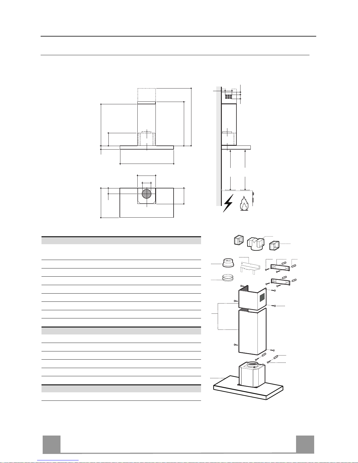
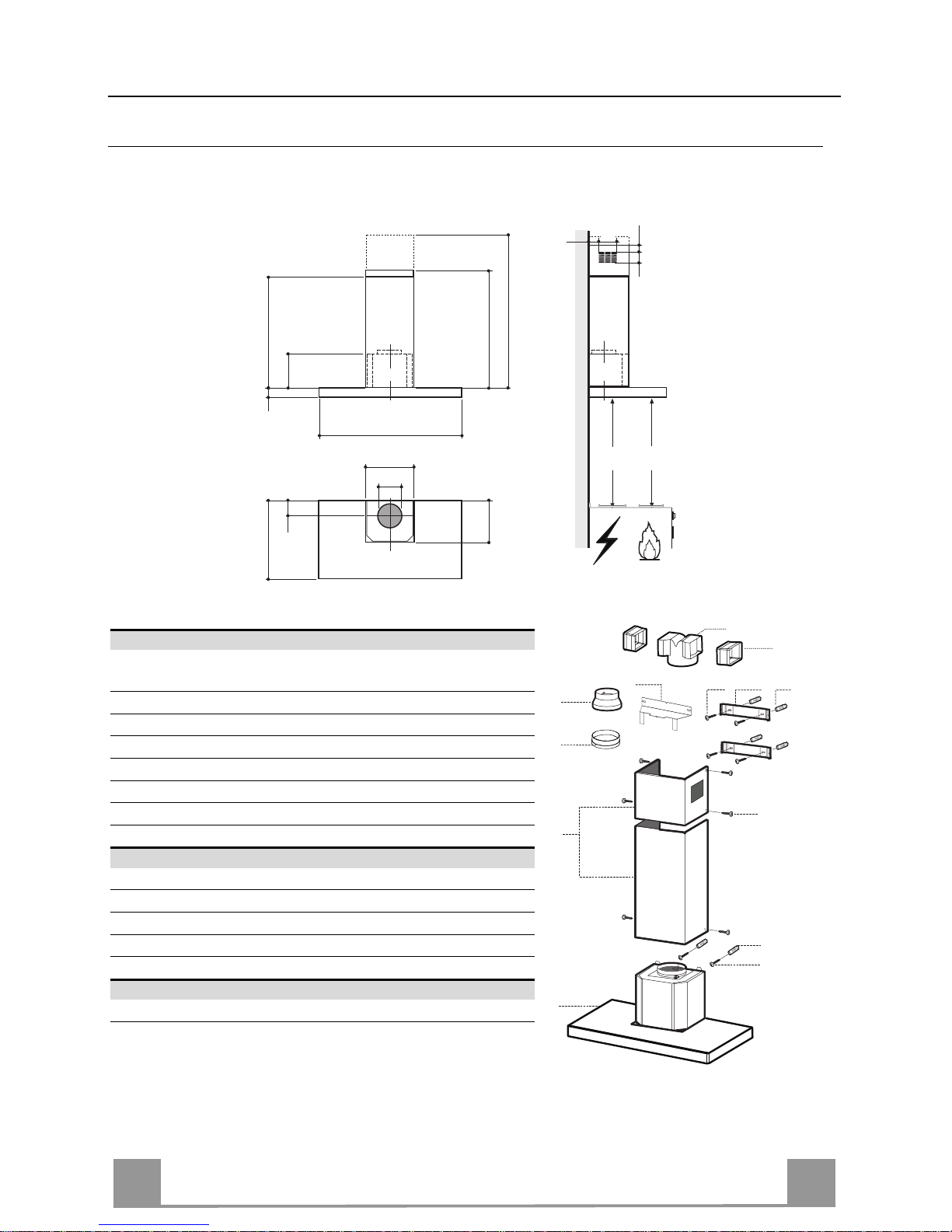
CARATTERISTICHE
Ingombro
490
60
108 259
150
min. 670
max. 1000
545
260
300
598-898-1198
Min.
500mm
Min.
650mm
81
6341126
Componenti
Rif. Q.tà Componenti di Prodotto
1 1 Corpo Cappa completo di: Comandi, Luce, Gruppo
Ventilatore, Filtri
2 1 Camino Telescopico formato da:
2.1 1 Camino Superiore
2.2 1 Camino Inferiore
9 1 Flangia di Riduzion e ø 150-120 m m
10 1 Anello di Maggiorazione ø 120-125 mm
14.1 2 Prolunga Raccordo Uscita Aria
15 1 Raccordo Uscita Aria
Rif. Q.tà Componenti di Installazione
7.2.1 2 Staffe Fissaggio Cami no Su periore
7.3 1 Staffa Sostegno Raccordo
11 6 Tasselli
12a 6 Viti 4,2 x 44,4
12c 6 Viti 2,9 x 9, 5
Q.tà Documentazione
1 Libretto Istruzioni
2.1
2.2
2
12c
12a
7.2.1 11
11
12a
1
9
7.3
14.1
15
10
Page 6
IT
6
6
7.3
11
12a
320
X
116
1÷2
116
650 min.
7.2.1
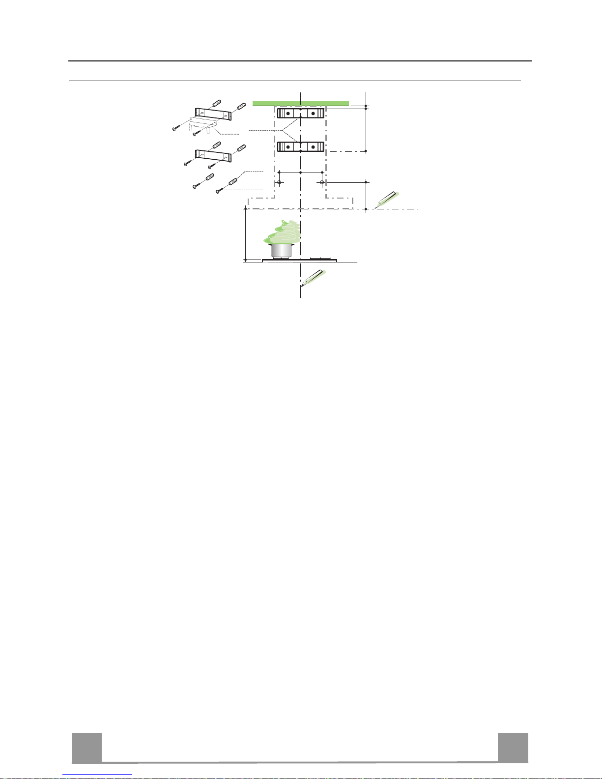
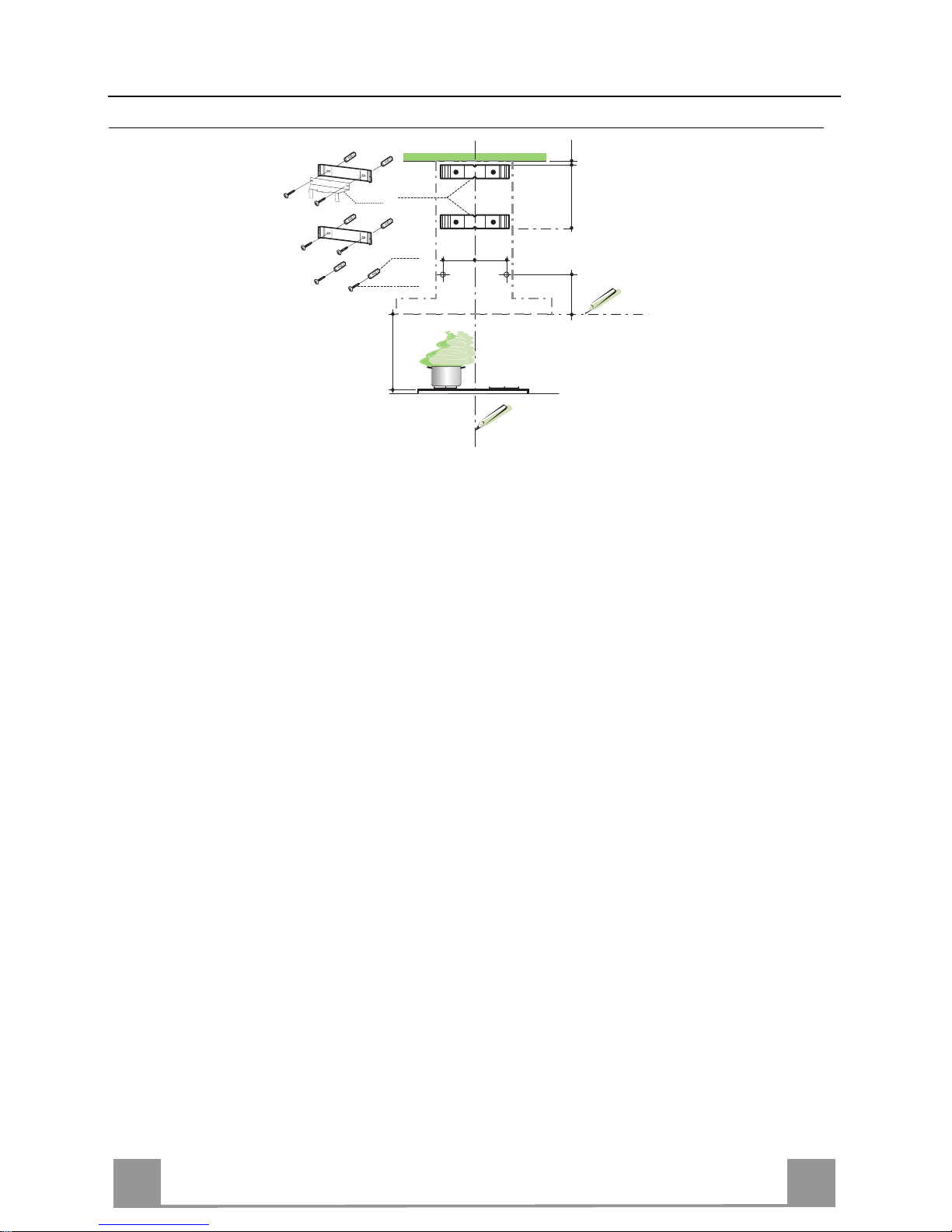
INSTALLAZIONE
Foratura Parete e Fissaggio Staffe
Tracciare sulla Parete:
• una linea Verticale fino al soffitto o al limite superiore, al centro della zona prevista per il
montaggio della Cappa;
• una linea Orizzontale a: 650 mm min. sopra il Piano di Cottura.
• Appoggiare co me ind icat o l a Staffa 7.2.1 a 1-2 mm dal soffitto o dal limite superiore, allineando il suo centro (intagli) sulla linea Verticale di riferimento.
• Segnare i centri dei Fori della Staffa.
• Appoggiare come ind icato la Staffa 7.2.1 a X mm sotto la p rima staffa (X = altezza Ca mino
Superiore in dotazione), allineando il suo centro (intagli) sulla linea Verticale di riferimento.
• Segnare i centri dei Fori della Staffa.
• Segnare come indicato, un punto di riferimento a 116 mm dalla linea Verticale di riferimento, e 320 mm sopra la linea Orizzontale di riferimento.
• Ripetere questa operazione dalla parte opposta.
• Forare ø 8 mm i punti segnati.
• Inserire i tasselli 11 nei fori.
• Fissare la Staffa inferiore 7.2.1 utilizzando le Viti 12a (4,2 x 44,4 ) in dotazione.
• Fissare insieme la Staffa superiore 7.2.1 e la Staffa sostegno racc ordo 7.3 utilizzando le 2
viti 12a (4,2 x 44,4) in dotazione.
• Avvitare 2 Viti 12a (4,2 x 44,4) in dotazione nei fori per il fissaggio del corpo Cappa, la-
sciando uno spazio di 5-6 mm fra la parete e la testa della vite.
Page 7
IT
7
7
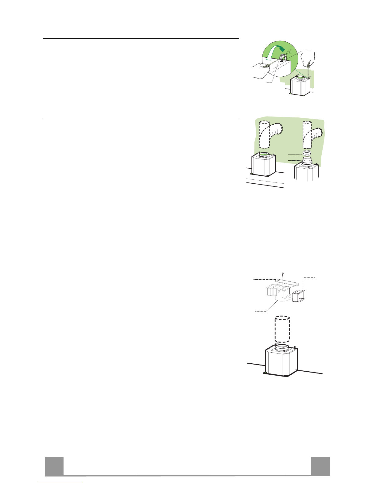
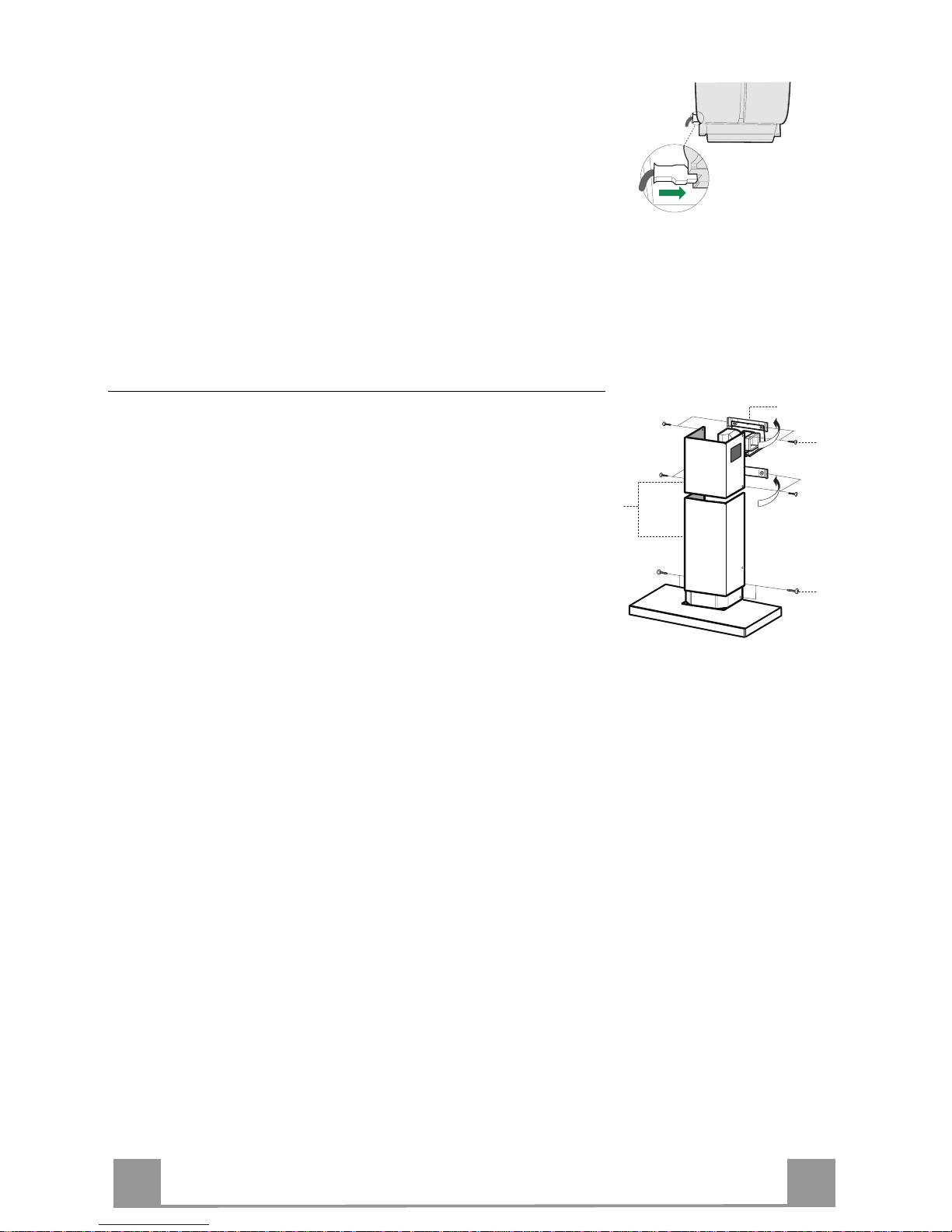
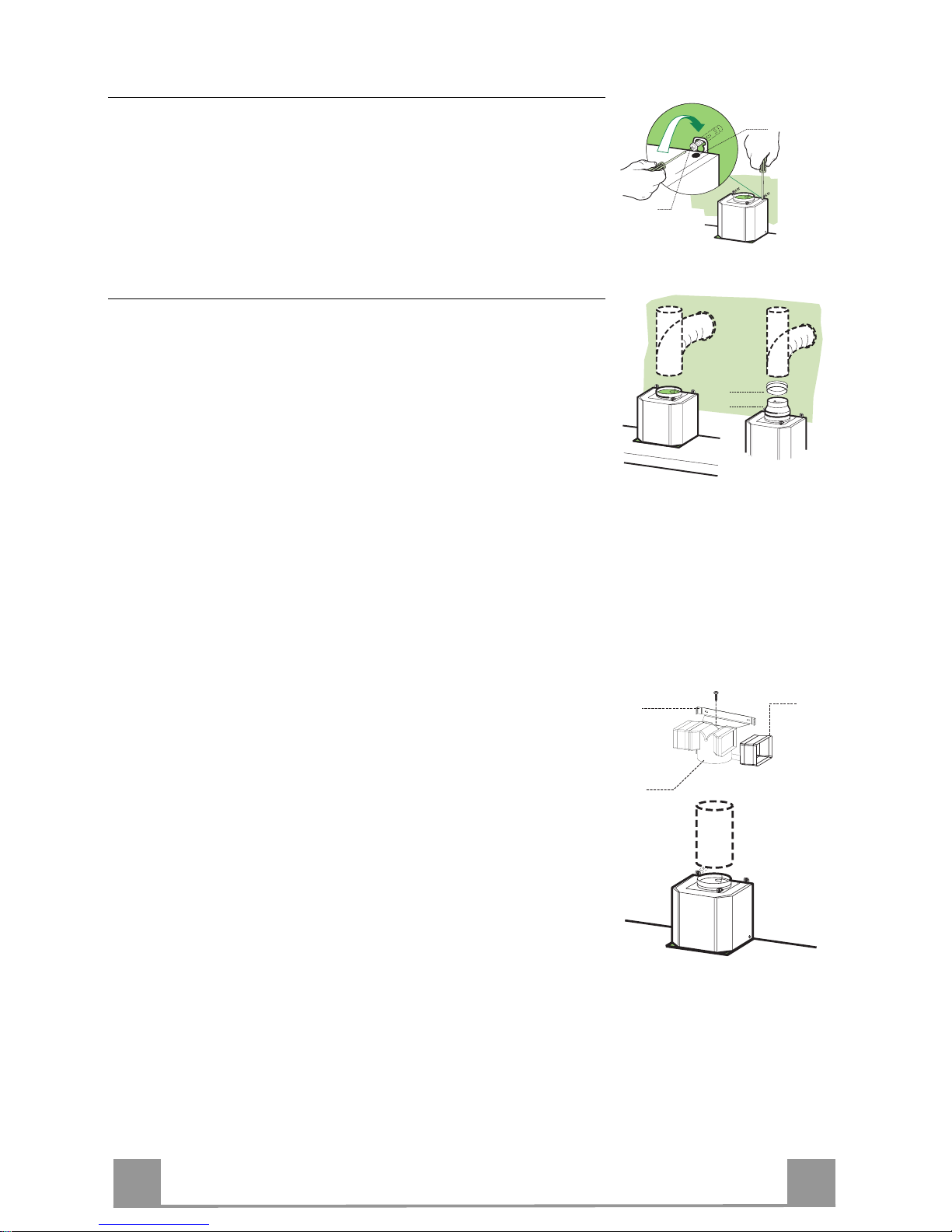
Montaggio Corpo Cappa
• Prima di agganciare il Corpo Cappa, serrare le 2 Viti Vr situate
sui punti di aggancio del Corpo Cappa.
• Agganciare il Corpo Cappa alle Viti 12a.
• Serrare definitivamente le Viti 12a di supporto.
• Agire sulle Viti Vr per livellare il Corpo Cappa.
12a
Vr
Connessioni
USCITA ARIA VERSIONE ASPIRANTE
Per installazione in Versione Aspirante collegare la Cappa alla
tubazione di uscita per mezzo di un tubo rigido o flessibile di
ø150 o 125 mm, la cui scelta è lasciata all'installatore.
• Per collegamento con tubo ø125 mm, inserire la Flangia di riduzione 9 sull’Uscita del Corpo Cappa e l’anello di maggiorazione 10 ø120-12 5 sulla Fla ng ia .
• Fissare il tubo con adeguate fascette stringitubo. Il materiale
occorrente non è in dotazione.
• Togliere eventuali Filtri Antiodore al Carbone attivo.
9
ø 125ø 150
10
USCITA ARIA VERSIONE FILTRANTE
• In serire lateralmente le P rolunghe Racco rdo 14.1 sul Raccordo
15.
• Inserire il Raccord o 15 nella Staffa di Sostegno 7.3 fissandolo
con una Vite.
• Assicurarsi che l’uscita delle Prolunghe Raccordo 14.1 risulti
in corrispondenza delle bocchette del Camino sia in orizzontale
che in verticale.
• Collegare i l Raccordo 15 all’Uscita del Corpo Cappa per mezzo di un tubo rigido o flessibile di ø150 mm, la cui scelta è lasciata all'installatore.
• Assicurarsi della presenza del Filtro Antiodore al Carbone attivo.
ø 150
15
14.1
7.3
Page 8
IT
8
8
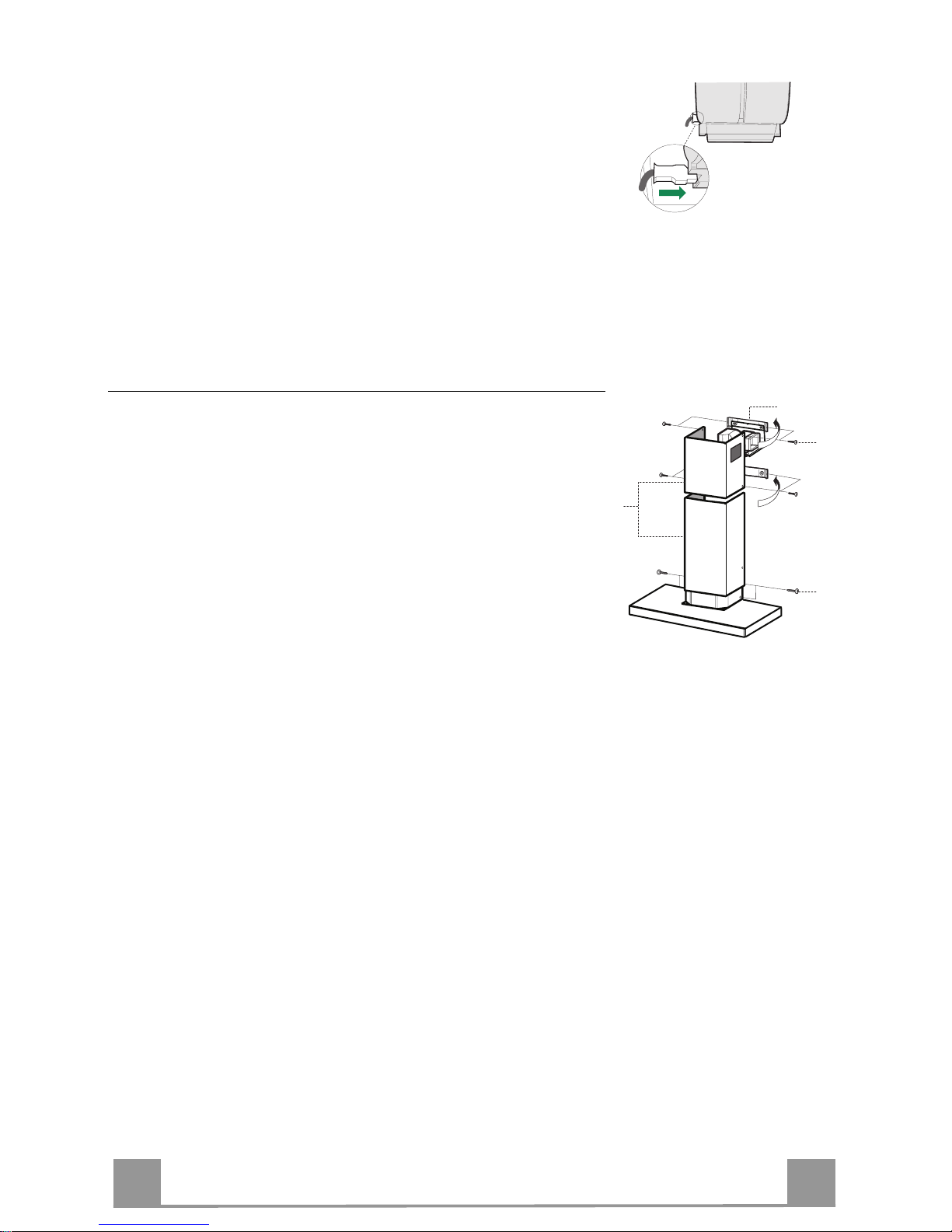
CONNESSIONE ELETTRICA
• Collegare la Cappa all’Alimentazione di Rete interponendo un
Interruttore bipolare con apertura dei contatti di almeno 3 mm.
• Rimuovere i Filtri antigrasso (vedi par. “Manutenzione”) e assicurarsi che il connettore del Cavo di alimentazione sia correttamente inserito nella presa dell’Aspiratore
Montaggio Camino
Camino superiore
• Allargare leggermente le due falde laterali, agganciarle dietro
le Staffe 7.2.1 e richiuderle fino a battuta.
• Fissare lateralmente alle Staffe con 4 Viti 12c (2,9 x 9,5) in
dotazione.
• Assicurarsi che l’uscita delle Prolungh e Raccordo risulti in corrispondenza delle boc che tte de l Camino.
Camino inferiore
• Allargare leggermente le due falde laterali del Camino, agganciarle tra il Camino superiore e la parete e richiuderle fino a
battuta.
• Fissare lateralmente la parte inferiore al Corpo Cappa, con 2
Viti 12c (2,9 x 9, 5) in dotazione.
12c
2.1
2.2
2
7.2.1
12c
Page 9
IT
9
9
USO
T2
T1
L
T3
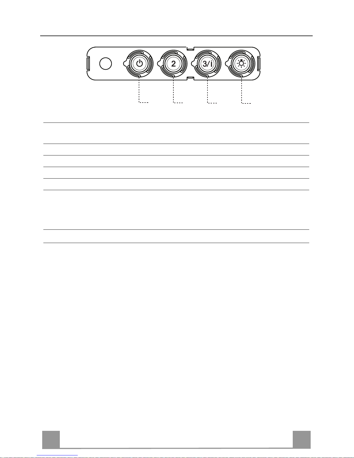
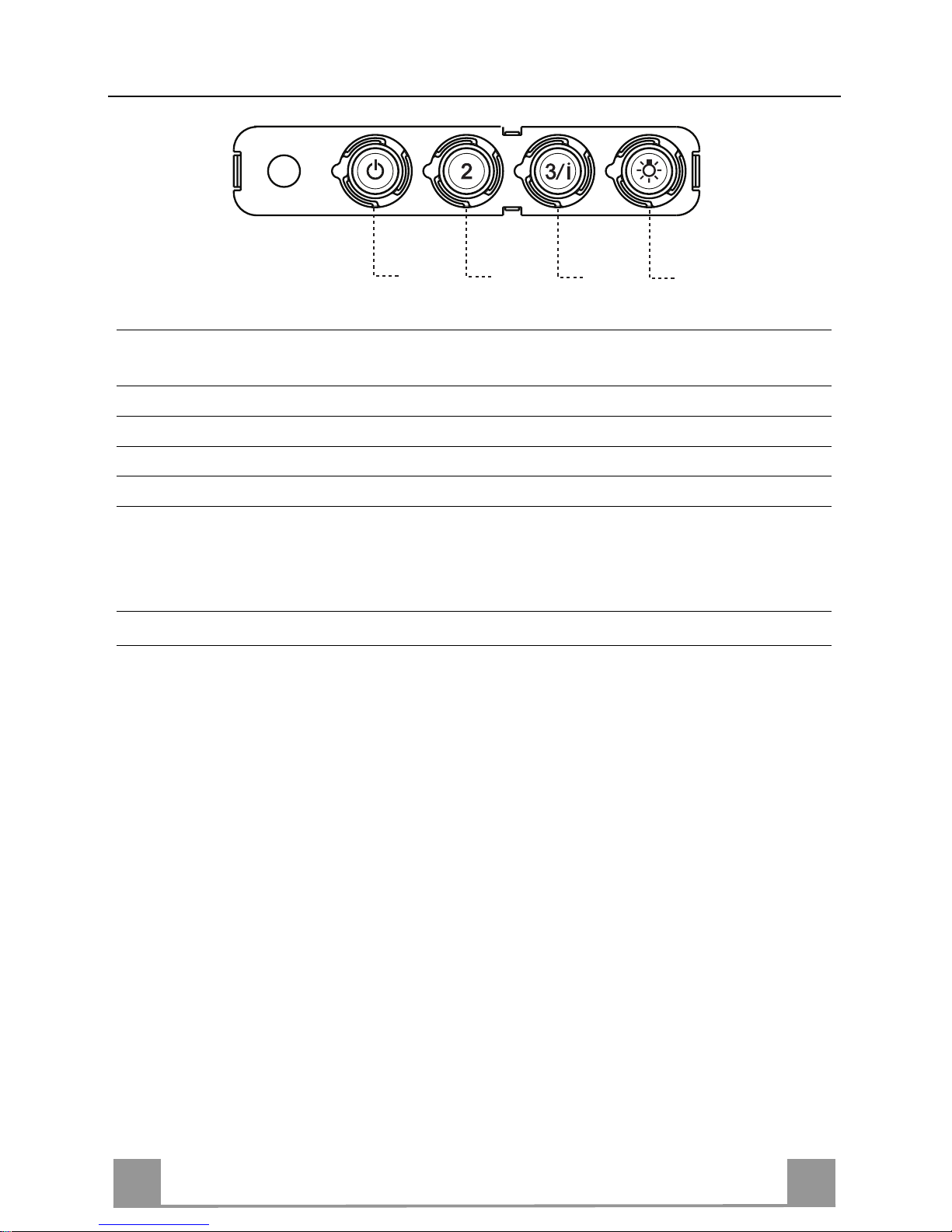
Quadro comandi
TASTO LED FUNZIONI
T1 Velocità Acceso Accende il Motore alla Prima velocità.
Spegne il Motore.
T2 Velocità Acceso Accende il Motore alla Seconda velocità.
T3 Velocità Fisso Premuto brevemente Accende il Motore alla Terza velocità.
Lampegg ia nte Premuto per 2 Second i .
Attiva la Quarta velocità temporizzata a 10 minuti, al termine
dei quali ritorna alla velocità precedentemente impostata. Adatta a fronteggiare le massime emissioni di fumi di cottura.
L Luce Accende e spegne l’Impianto di Illuminazio ne.
Attenzione: Il tasto T1 spegne il motore passando sempre per la prima velocità.
Page 10
IT 110
MANUTENZIONE
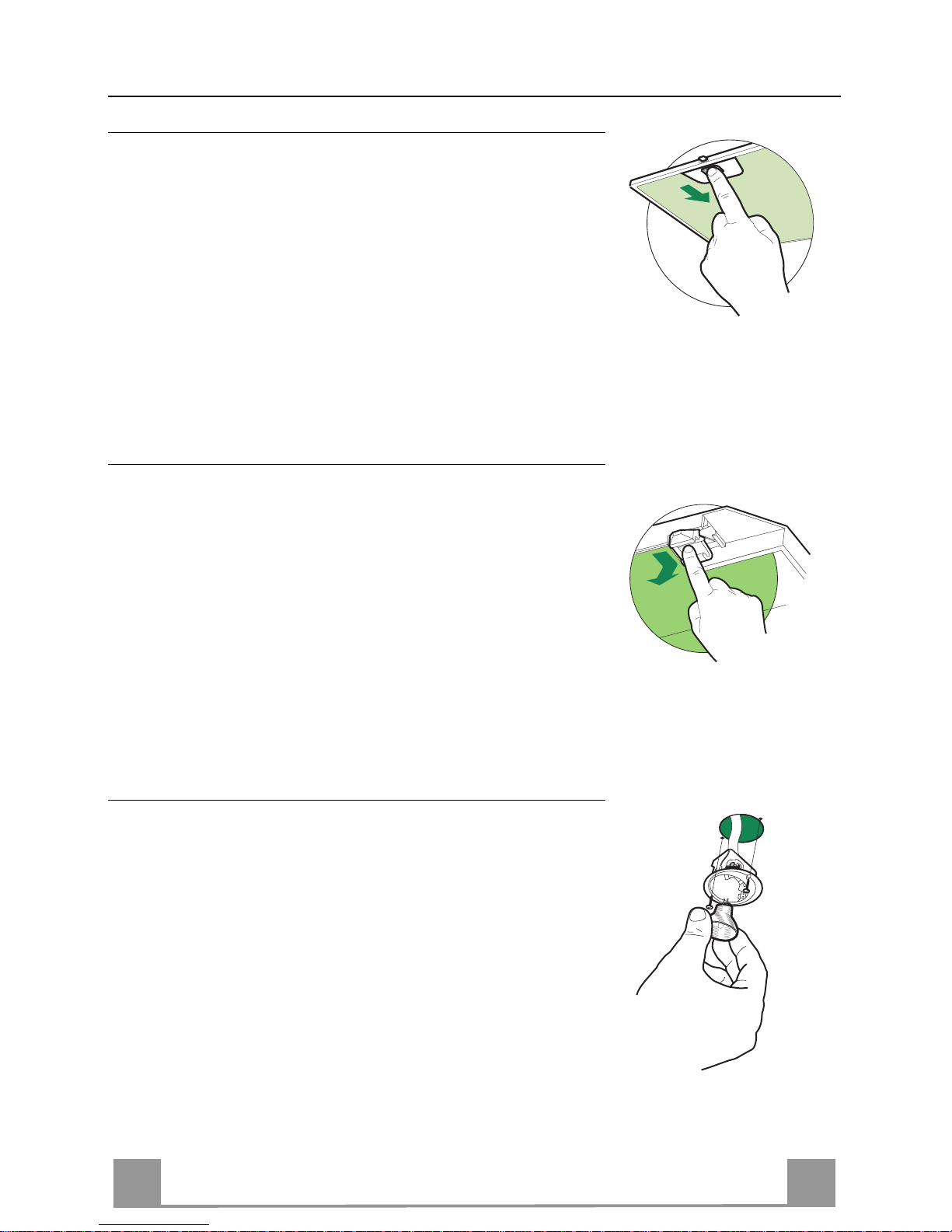
Filtri antigrasso
PULIZIA FILTRI ANTIGRASSO METALLICI AUTOPORTAN TI
• Sono lavabili anche in lavastoviglie, e necessitano di essere
lavati ogni 2 mesi circa di utilizzo o più frequentemente, per un
uso particolarmente intenso.
• Togliere i Filtri uno alla volta, spingendoli verso la parte posteriore del gruppo e tirando contemporaneamente verso il b asso.
• Lavare i Filtri evitando di piegarli, e lasciarli asciugare prima
di rimontarli.
• Rimontarli facendo attenzione a mantenere la maniglia verso la
parte visibile esterna.
Filtro antiodore (Versione Filtrante)
SOSTITUZIONE FILTRO ANTIODORE AL CARBONE ATTIVO
• Non è lavabile e non è rigenerabile, va sostituito almeno ogni 4
mesi o più frequentemente, per un uso particolarmente intenso.
• Togliere i Filtri antigrasso metallici.
• Rimuovere il Filtro antiodore al Carbone attivo saturo, agendo
sugli appositi agganci.
• Montare il nuovo Filtro agganciandolo nella sua sede.
• Rimontare i Filtri antigrasso metallici.
Illuminazione
SOSTITUZIONE LAMPADE
Lampade alogene d a 20 W.
• Togliere le due viti che fissano il Supporto illuminazione e sfilarlo dalla Cappa.
• Estrarre la Lampada dal Supporto.
• Sostituirla con una nuova di uguali caratteristiche, facendo attenzione di inserire correttamente i due spinotti nella sede del
Supporto.
• Rimontare il Supporto fissandola con le due Viti precedentemente tolte.
Page 11
EN
111
RECOMMENDATIONS AND SUGGESTIONS
The Instructi ons for Us e appl y t o seve ral ver sio ns of this appli anc e. Ac cor
d-
ingly, you may find descriptions of in dividual features th at do not apply to
your specific appliance.
INSTALLATION
• The manuf acturer will not be hel d liable for any dama ges resulting from incorrect or i mpr op er ins tal lat ion .
• The minimum safety distance between the cooker top and the extractor
hood is 650 m m (som e m od el s c an be installe d at a lower hei gh t, p l ea se refer to the paragraphs on working dimensions and installation).
• Check that the mains voltage corresponds to that indicated on the rating
plate fixed to the inside of the hood.
• F or Class I appliances, check th at the domestic power suppl y guarantees
adequate earthing.
Connect the extr act or to the e xhaus t flu e throu gh a pi pe of m inimum diam e-
ter 120 mm. The route of the flue must be as short as possible.
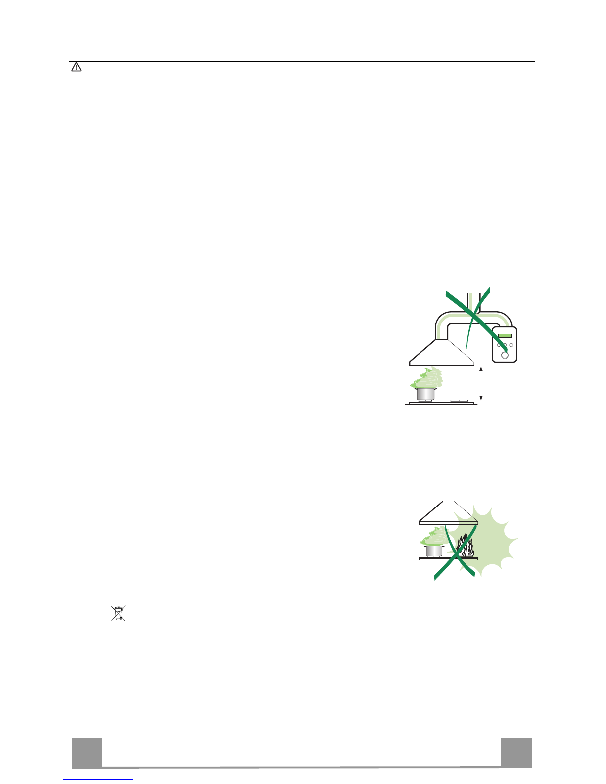
• Do not connect the extractor hood to exhaust ducts carrying combustion
fumes (boilers, fireplaces, etc.).
• If the extractor is us ed in conjunctio n wit h no n-electrical appliances ( e. g. g as
burning appl iances), a s ufficient degree of aeration mu st be guarant eed in
the room in orde r to preve nt the backflow of ex haust gas. The kit chen mus t
have an open ing com municating directly wi th the o pen air in order t o guarantee the entry of clean air.
USE
• The extractor hood has been designed exclusively for domestic use to eliminate kitchen smells.
• Never use the hood for purposes other than for which it has been designed.
• Never le a ve hi gh na ke d fl a me s unde r the ho od wh en i t is in op er at ion .
• Adjust the flame in te nsity to direct it onto the bottom o f t he pa n o nl y, m aki ng
sure that it does not engulf the sides.
• Deep fat f ryers must be conti nuously monit ored during use: overheated oil
can burst into flames.
• Do not flambè under the range hood; risk of fire
• This appli ance is not inten ded for use by pers ons (including chi ldren) with
reduced physi cal, sensory or m ental capabi lities, or lack o f experience an d
knowledge, unl ess th ey have been g iven su pervis ion o r instr ucti on con cern ing use of the appliance by a person responsible for their safety.
• Children should be s up ervised to ens ur e that they do not play with the appliance.
MAINTENANCE
• Switch off or unplug t he a ppliance from the m ains supply before ca rr yi n g ou t
any maintenance work.
• Clean and/or replace the Filters after the specified time period (Fire hazard).
• Clean the hood using a damp cloth and a neutral liquid detergent.
The symbol on the product or on its packaging indicates that this product may not be treated
as household waste. Instead it shall be handed over to the applicable collection point for the
recycling of el ectr i cal and electro ni c equipment. By ensurin g t hi s product i s di s p osed of c or rectly,
you will help prevent potential negative consequences for the environment and human health,
which could otherwise be caused by inappropriate waste handling of this product. For more
detailed information about recycling of this product, please contact your local city office, your
household waste disposal service or the shop where you purchased the product.
650 mm min.
Page 12
EN
112
CHARACTERISTICS
Dimensions
490
60
108 259
150
min. 670
max. 1000
545
260
300
598-898-1198
Min.
500mm
Min.
650mm
81
6341126
Components
Ref. Q.ty Product Components
1 1 Hood Body, complete with: Controls, Light, Blower,
Filters
2 1 Telescopic Chimney comprising:
2.1 1 Upper Section
2.2 1 Lower Section
9 1 Reducer Flange ø 150-120 mm
10 1 Adapting ring ø 120-125 mm
14.1 2 Air Outlet Conn ection Ext ension
15 1 Air Outlet C onnection
Ref. Q.ty Installation Components
7.2.1 2 Upper Chimney Section Fixing Brackets
7.3 1 Air Outlet Connect ion Support
11 6 Wall Plugs
12a 6 Screws 4,2 x 44,4
12c 6 Screws 2,9 x 9,5
Q.ty Documentation
1 Instruction Manual
2.1
2.2
2
12c
12a
7.2.1 11
11
12a
1
9
7.3
14.1
15
10
Page 13
EN
113
7.3
11
12a
320
X
116
1÷2
116
650 min.
7.2.1
INSTALLATION
Wall drilling and bracket fixing
Wall marking:
• Draw a vertical line on the supporting wall up to the ceiling, or as high as practical, at the
centre of the area in which the hood will be installed.
• Draw a horizontal line at 650 mm above the hob.
• Place bracket 7.2.1 on the wall as shown about 1-2 mm from the ceiling or upper limit aligning the centre (n otch) with the vertical reference line.
• Mark the wall at the centres of the h oles in the bracket.
• Place bracket 7.2.1 on the wall as shown at X mm below the first bracket (X = height of the
upper chimney section supplied), aligning the centre (notch) with the vertical line.
• Mark the wall at the centres of the h oles in the bracket.
• Mark a reference poi nt as indicated at 116 mm from the vertical referen ce line and 320 mm
above the horizontal reference line.
• Repeat this operation on the other side.
• Drill ø 8 mm holes at all the centre points marked.
• Insert the wall plugs 11 in the holes.
• Fix the lower bracket 7.2.1 using the 12a screws (4,2 x 44,4) supplied.
• Fix the upper bracket 7.2.1 and the air outlet connection support 7.3 together using the 2
screws 12a (4,2 x 44,4) supplied.
• Insert the two screws 12a (4,2 x 44,4) supplied in the hood body fixing holes, leaving a gap
of 5-6 mm between the wall and the head of the screw.
Page 14
EN
114
Mounting the hood body
• Before attaching the hood body, tighten the two screws Vr located on the hood body mounting points.
• Hook the hood body onto the screws 12a.
• Fully tighten the support screws 12a.
• Adjust the screws Vr to level the hood body.
12a
Vr
Connections
DUCTED VERSION AIR EXHAUST SYSTEM
When installing the ducted version, connect the hood to the
chimney using either a flexible or rigid pipe ø 150 or 125 mm,
the choice of which is left to the in staller.
• To install a ø 125 mm air exhaust connection, insert the reducer flange 9 on the hood body air outlet and the adapting
ring ø120-125 10 on the reducer flange.
• Fix the pipe in position using sufficient pipe clamps (not supplied).
• Remove an y activated charcoal filters.
9
ø 125ø 150
10
RECIRCULATION VERSION AIR OUTLET
• Insert the conn ection exten sion pieces lat erally 14.1 in co nnection 15.
• Insert the Co nnector 15 into t he Support bracket 7.3 and fix it
with a screw.
• Make sure that the out let of the extension pieces 14.1 is horizontally and vertically aligned with the chimney outlets.
• Connect the air outlet connection 15 to the hood body outlet
using either a flexible or rigid pipe ø 150 mm, the choice of
which is left to the installer.
• Ensure that the activated charcoal filters have been inserted.
ø 150
15
14.1
7.3
Page 15
EN
115
ELECTRICAL CONNECTION
• Connect the hood to the mains through a two-pole switch having a contact gap of at least 3 mm.
• Remove the grease filters (see paragraph Maintenance) being
sure that the co nnector of the feeding cable is correctly inserted
in the socket placed on the side of th e fan.
Flue assembly
Upper exhaust flue
• Slightly widen the two sides of the upper flue and hook them
behind the brackets 7.2.1, making sure that they are well
seated.
• Secure the sides to the brackets by using the 4 screws 12c (2,9
x 9,5) supplied.
• Make sure that the outlet of the extensions pieces is aligned
with the chimney outlets.
Lower exhaust flue
• Slightly widen the two sides of the flue and hook them between the upper flue and the wall, making sure t hat they are
well seated.
• Fix the lower part laterally to the hood body by using the 2
screws 12c (2,9 x 9,5) supplied.
12c
2.1
2.2
2
7.2.1
12c
Page 16
EN
116
USE
T2
T1
L
T3
Control panel
BUTTON LED FUNCTIONS
T1 Speed On Turns the Motor on at Speed one.
Turns the Motor off.
T2 Speed On Turns the Moto r on at Speed two.
T3 Speed Fixed When pressed briefly, turns t he Motor on at Speed three.
Flashing Pressed for 2 Seconds.
Activates Speed four with a timer set to 10 minutes, after
which it returns to the speed that was set previously. Suitable
to deal with maximum levels of c ooking fumes.
L Light Turns the Lighting S ystem on and off.
Warning: Button T1 turns the motor off, after first passing to speed one.
Page 17

EN
117
MAINTENANCE
Grease filters
CLEANING METAL SELF- SUPPORTI NG GREASE FILTERS
• The filters must be cleaned every 2 months of operation, or
more frequently for particularly heavy usage, and can be
washed in a dishwasher.
• Remove the filters one at a time by pushing them towards the
back of the group and pulling down at the same time.
• Wash the filters, taking care not to bend them. Allow them to
dry before refitting.
• When refitting the filters, ma ke sure that the handle is visible
on the outside.
Activated charcoal filter (Recirculation version)
REPLACING THE ACTIVATED CHARCOAL FIL T ER
• The filter is not washable and cannot be regenerated, and must
be replaced approximately every 4 months of operation, or
more frequently for particularly heavy usage.
• Remove the metal grease filters.
• Remove the saturated activated carbon filter by releasing the
fixing hooks.
• Fit the new filter by hooking it into its seating.
• Refit the metal grease filters.
Lighting
LIGHT REPLACEMENT
20 W halogen light.
• Remove the 2 screws fixing the Lighting support, and pull it
out of from the Hood.
• Extract the lamp from the Support.
• Replace with another of the same type, making sure that the
two pins are properly inserted in the lamp holder socket holes.
• Refit the Support, fixing it in place with the two screws removed as above.
Page 18

FR
118
CONSEILS ET SUGGESTIONS
La présente notice d'emploi vaut pour plusieurs versions de l'appareil. Elle peut conte-
nir des descriptions d'access oir es ne fi gurant pas dan s vot re apparei l.
INSTALLATION
• Le fabricant décline toute responsabilité en cas de dommage dû à une ins talla tion non
correcte ou non conforme aux règl es d e l’ art.
• La distance minimale de sécurité entre le plan de cuisson et la hotte doit être de 650
mm au moins (certains modèles peuvent être installés à une hauteur inférieure : se reporter aux paragraphe s « Encombrem ent » et « Instal lati on »).
• Vérifier que la tension du secteur correspond à la valeur qui figure sur la plaquette
apposée à l’intérieur de la hotte.
• Pour les Appareils appartenant à la Ière Classe, veiller à ce que la mise à la te rre de
l’installation électrique domestique ait été effectuée conformément aux normes en vigueur.
• Connecter la hotte à la sortie d’air aspir é à l’aide d’une tuyauterie d’ un diamètre égal ou
supérieur à 120 mm. Le parcours de l a tuyaut eri e doit être le plus court possibl e.
• Ne pas connecter la hotte à des conduites d’évacuation de fumées issues d’une combustion tel que (Chaudi ère, chemi née, et c…).
• Si vous utilisez des appareils qui ne foncti onnent pas à l’électricité dans l a pièce ou est
installée la hotte (par exemple: des appareils fonctionnant au gaz), vous devez prévoir
une aération suffisante du milieu. Si la cuisine en est dépourvue, pratiquez une ouverture qui communique avec l ’ext érieur pour garant ir l’infil trati on de l’ai r pur.
UTILISATION
• La hotte a été conçue exclusivement pour l’usage domestique, dans le but d’éliminer
les odeurs de la cuisine.
• Ne jamais utiliser abusi vement l a hott e.
• Ne pas laisser les flammes li bres à forte int ensit é quand la hott e est en ser vice.
• Toujours régler les flammes de manière à éviter toute sortie latérale de ces dernières
par rapport au fond des marmit es.
• Contrôler les frit euses lors de l ’uti lisat ion car l’huile sur chauff ée pourrai t s’ enfl ammer.
• Ne pas préparer d’alim ents fl ambés sous la hot te de cui sine : ri sque d’ incendi e
• Cet appareil ne doit pas être utilisé par des personnes (y compris les enfants) ayant
des capacités psychiques, sensorielles ou mentales réduites, ni par des personnes
n’ayant pas l’expérience et la connaissance de ce type d’apparei ls, à moins d'être sous
le contrôle et la formati on de personn es respo nsables de l eur sécuri té.
• Les enfants doivent être surveillés pour s'assurer qu'ils ne jouent pas avec l'appareil.
ENTRETIEN
• Avant de procéder à toute opération d’entretien, débrancher la hotte en retirant la fiche
ou en actionnant l’int err upteur génér al.
• Effectuer un entretien scrupuleux et en temps dû des Filtres, à la cadence conseillée
(Risque d’incendie) .
• Pour le nettoyage des surfaces de la hotte, il suffit d’utiliser un chiffon humide et détersif liquide neutre.
Le symbole sur le produit ou son emballage indique que ce produit ne peut être traité comme
déchet ménager. Il doit plutôt être remis au point de ramassage concerné, se chargeant du recyclage du matériel électrique et électronique. En vous assurant que ce produit est éliminé correctement, vous favorisez la prévention des conséquences négatives pour l’environnement et la santé
humaine qui, sinon, seraient le résultat d’un traitement inapproprié des déchets de ce produit. Pour
obtenir plus de détails sur le recyclage de ce produit, veuillez prendre contact avec le bureau municipal de votre région, votre service d’élimination des déchets ménagers ou le magasin où vous avez
acheté le produit.
650 mm min.
Page 19

FR
119
CARACTERISTIQUES
Encombrement
490
60
108 259
150
min. 670
max. 1000
545
260
300
598-898-1198
Min.
500mm
Min.
650mm
81
6341126
Composants
Réf. Q.té Composants de Produit
1 1 Corps Hotte équipé de:Comandes, Lumière,Groupe
Ventilateur,Filtres
2 1 Cheminée Télescopique formée de :
2.1 1 Cheminée Supérieure
2.2 1 Cheminée Inférieure
9 1 Flasque de Réduction ø 150-1 20 mm
10 1 Anneau de raccord Ø 12 0 - 125 mm
14.1 2 Rallonge Raccord Sortie Air
15 1 Raccord Sortie Air
Réf. Q.té Composants pour l ’installation
7.2.1 2 Brides Fixation Ch emi né e Su péri eur e
7.3 1 Bride Support Raccord
11 6 Chevilles
12a 6 Vis 4,2 x 44,4
12c 6 Vis 2,9 x 9,5
Q.té Documentation
1 Manuel d’instructions
2.1
2.2
2
12c
12a
7.2.1 11
11
12a
1
9
7.3
14.1
15
10
Page 20

FR
220
7.3
11
12a
320
X
116
1÷2
116
650 min.
7.2.1
INSTALLATION
Perçage Paroi et Fixation Brides
Tracer sur la paroi:
• une ligne verticale allant jusqu’au plafond ou à la limite supérieure, au centre de la zone
prévue pour le montage de la hotte;
• une ligne horizontale à 650 mm min. au-dessus du plan de cuisson.
• Poser comme indiqué une bride 7.2.1 sur la paroi à 1-2 mm du plafond ou de la limite supé-
rieure, en alignant son centre (découpes) su r la ligne verticale de repère.
• Marquer les centres des trous rainurés de la bride.
• Poser comme indiqué la bride 7.2.1 à X mm sous la première bride (X = hauteur cheminée
supérieure fournie), en alignant son cent r e (découpes) sur la ligne verticale de repère.
• Marquer les centres des trous rainurés de la bride.
• Marquer comme indiqué, un point de référence à 116 mm de la ligne verticale de repère, et
320 mm au-dessus de la ligne horizontale de repère.
• Répéter cette opération sur le cô té opposé.
• Percer de ø 8 mm tous les points marqués.
• Insérer les chevilles 11 dans les trous.
• Fixer la bride inférieure 7.2.1 en utilisant les vis 12a (4,2 x 44,4) fournies.
• Fixer ensemble la bride supérieure 7.2.1 et le support 7.3 en utilisant les vis 12a (4,2 x 44,4)
fournies.
• Visser les 2 vis 12a (4,2 x 44,4) fournies dans les trous de fixation du corps hotte, en laissant
un le espace de 5-6 mm entre le mur et la tête de la vis
Page 21

FR
221
Montage Corps Hotte
• Avant d’accrocher le corp s hotte, serrer les deux vis Vr situées
sur les points d’accro chage du corps hott e.
• Accrocher le corps hotte aux vis 12a prévues à cet effet.
• Serrer définitivement les vis 12a de support.
• Agir sur les vis Vr pour niveler le corps hotte.
12a
Vr
Connexions
SORTIE DE L'AIR EN VERSION EVACUATION
Pour l’installation dans la Version Aspirante, connecter la hotte au tuyau
d’évacuation, au moyen d’un tuyau rigide ou flexible de ø 150 ou 125
mm, que l’installateur pourra choisir à son propre gré.
• Pour raccord de ø 125 mm, insérer la bride de réduction 9 sur la sorti e
du corps de hotte et l’anneau d’agrandissement 10 de ø 120-125 mm
sur la bride.
• Fixer le tuyau à l’aide du collet serre-tuyaux. Le matériel nécessaire
n'est pas fourni avec l'appareil.
• Retirer les filtres anti-odeur au charbon actif, s’ils sont montés.
9
ø 125ø 150
10
SORTIE AIR VERSION FILTRANTE
• Insérer latéralement les rallonges raccord 14.1 sur le raccord
15.
• Placer le raccord 15 dans l’étrier de soutien 7.3 en le fixant
avec une vis.
• S’assurer que la sort ie des rallonges raccord 14.1 se trouve au
niveau des bouches de la cheminée aussi bien en horizontal
qu’en vertical.
• Brancher l e raccord 15 à la sortie du corps de la hotte avec un
tube rigide ou flexible de ø 150 mm, selon le choix de
l’installateur.
• S’assurer de la présence des filtres anti-odeur au charbon actif.
ø 150
15
14.1
7.3
Page 22

FR
222
BRANCHEMENT ELECTRIQUE
• Bran cher la hotte sur le secteur en interposant un interrupteur
bipolaire avec ouverture des contacts d’au moins 3 mm.
• Enlever les filtres à graisse (voir § "Entretien") et s 'assurer que
le connecteur du câb le d 'alimentati on so it bi en bran ché dan s la
prise du diffuseur.
Montage Cheminée
Cheminée supérieure
• Elargir légère ment les deux bords latériaux, et les accrocher
derrières les brides 7.2.1 ; refermer
jusqu’à la butée.
• Fixer latéralement aux brides à l’aide des 4 vis
12c fournies.
• S’assurer que la sortie des rallonges raccord se trou ve au niveau des bouches de la cheminée.
Cheminée inférieure
• Elargir légèrement les deux bords latériaux de la Cheminée et
les accrocher entre la Cheminée s upérieure et la paroi; refermer
jusqu’à la butée.
• Fixer latéralement la partie inférieure au corps
hotte, à l’aide des deux 2 vis 12c fournies.
12c
2.1
2.2
2
7.2.1
12c
Page 23

FR
223
UTILISATION
T2
T1
L
T3
Tableau des commandes
TOUCHE VOYANT FONCTIONS
T1 Vitesse Allumé Démarre le moteur en première vitesse.
Coupe le moteur.
T2 Vitesse Allumé Démarre le moteur en deuxième vitesse.
T3 Vitesse Fixe Appuyée brièvement, démarre le moteur en troisième vitesse.
Clignotant Appuyée pendant 2 secondes.
Démarre la quatrième vitesse avec une temporisation de 10 mi-
nutes, après lesquel les le moteur retourne à la vitesse précéd emment programmée. Fonction indiquée pour faire face aux pointes
d’émission de fumées de cuisson.
L Lumière Branche et débranche l’éclairage.
Attention : La touche T1 coupe le moteur en passant toujours par la première vitesse.
Page 24

FR
224
ENTRETIEN
Filtres anti-graisse
NETTOYA GE FILTRES AN TI-GR AISSE M ETALLIQ UES AU TOPORTE URS
• Lavables au lave-vaisselle, ils doivent être lavés environ tous
les 2 mois d’emploi ou plus fréquemment en cas d’emploi particulièrement intense.
• Retirer les filtres l’un aprés l’autre, en les poussant vers la partie arrière du groupe et en tirant simultanément vers le bas.
• Laver les filtres en évitant de les plier et les laisser sécher avant
de les remonter.
• Remonter les filtres en veillant à ce que la poignée reste vers la
partie visible externe
Filtre anti-odeur (Version filtrante)
REMPLACEMENT FILTRE AU CHARBON ACTIF
• Ni lavable, ni régénérable, le remplacer au moins tous les 4
mois d’emploi ou plus fréquemment en cas d’emploi particulièrement intense.
• Retirer les filtres anti-graisse métalliques.
• Retirer le filtre anti-odeur au charbon actif colmaté, en agissant
sur les crochets prévu s à cet effet.
• Monter le nouveau filtre anti-odeur au charbon actif.
• Remonter les filtres anti-graisse métalliques.
Eclairage
REMPLACEMENT LAMPES
Lampe halogène de 20 W.
• Retirer les 2 Vis qui fixent le Support éclairage et ôter ce dernier de la Hotte.
• Extraire la Lampe du Support.
• Re mplacer par un e nouvelle lampe possédant les mêmes caractéristiques, en veillant à ce que les deux fiches soient correctement insérées dans le logement de la Douille.
• Remonter le Support en le fixant à l’aide des deux Vis précédemment retirées.
Page 25

DE
225
EMPFEHLUNGEN UND HINWEISE
Diese Gebrauchsanleitung gilt für mehrere Geräte
-
Ausführungen. Es ist möglich, dass
einzelne Ausstattungsmer kmal e besc hrieben si nd, di e nicht auf Ihr Ger ät zutref fen.
MONTAGE
• Der Hersteller haftet nicht für Schäden, die auf eine fehlerhafte und unsachgemäße
Montage zurückzuführen si nd.
• Der minimale Sicherheitsabstand zwischen Kochmulde und Haube muss 650 mm
betragen (einige Modelle können an einer geringeren Höhe installiert werden, beziehen
Sie sich dazu auf den Absatz R aumbed arf und I nstall ation) .
• Prüfen, ob die Netzspannung mit dem Wert auf dem im Haubeninneren angebrachten
Schild übereinsti mmt.
• Bei Geräten der Klasse I ist sicherzustellen, dass die elektrische Anlage des Wohnhauses über eine vorschr if tsmäßi ge Er dung ver fügt.
• Das Anschlussrohr der Haube zur Luftaustrittsöffnung muss einen Durchmesser von
120 mm oder darüber aufweisen. Der Rohrver lauf muss so kur z wi e mögli ch sein.
• Die Haube darf an keine Entlüftungsschächte angeschlossen werden, in die Verbrennungsgase (Heizkessel , K amine usw .) gel eitet wer den.
• Werden im Raum außer der Dunstabzugshaube andere, nicht elektrisch betriebene
(z.B. gasbetriebene) Geräte verwendet, muss für eine ausreichende Belüftung gesorgt
werden. Sollte die Küche diesbezüglich nicht entsprechen, ist an einer Aussenwand
eine Öffnung anzubri ngen, di e Fri schluf tzuf uhr gew ährlei stet .
BEDIENUNG
• Die Dunstabzugshaube ist ausschließlich zum Einsatz im privaten Haushalt und zur
Beseitigung von Küchen gerüc hen v orgese hen.
• Unsachgemäßer Einsat z der H aube ist zu unterl assen.
• Große Flammen bei eingesch al teter Haube ni emals unbe deckt l assen.
• Die Intensivität der Flamme ist so zu regulieren, dass sie den Topfboden nicht überragt.
• Frittiergeräte müssen während des Gebrauchs stets beaufsichtigt werden: überhitztes
Öl kann sich entzünden.
• Keine flambiert en Spei sen unter der A bzugshaube zub erei ten: Br andgefahr.
• Dieses Gerät darf nicht von Personen, auch Kindern, mit verminderten psychischen,
sensorischen und geistigern Fähigkeiten, oder von Personen ohne Erfahrung und
Kenntnisse benutzt werden, sofern sie nicht von für ihre Sicherheit verantwortlichen
Personen beaufsichti gt und bei m Gebr auch de s Ger äts angel eit et w erden.
• Kinder dürfen sich nicht unbeaufsichtigt in der Nähe des Geräts aufhalten und auf
keinen Fall mit dem Gerät spielen.
WARTUNG
• Bevor Wartungsarbeiten durchgeführt werden, muss die Stromzufuhr zur Haube unterbrochen werden, indem der Stecker gezogen oder der Hauptschalter abgeschaltet
wird.
• Bei der Filterwartung müssen die vom Hersteller empfohlenen Zeiträume zum Austauschen der Filter genauest ens eing ehal ten w erden (B randgef ahr ).
• Zur Reinigung der Haubenflächen Wir empfehlen ein feuchtes Tuch und ein mildes
Flüssigreinigungsmit t el .
Das Symbol auf dem Produkt oder seiner Verpackung weist darauf hin, dass dieses Produkt nicht
als normaler Haushaltsabfall zu behandeln ist, sondern an einem Sammelpunkt für das Recycling von
elektrischen und elektronischen Geräten abgegeben werden muss. Durch Ihren Beitrag zum korrekten
Entsorgen dieses Produkts schützen Sie die Umwelt und die Gesundheit Ihrer Mitmenschen. Umwelt
und Gesundheit werden durch falsches Entsorgen gefährdet. Weitere Informationen über das Recycling
dieses Produkts erhalten Sie von Ihrem Rathaus, Ihrer Müllabfuhr oder dem Geschäft, in dem Sie das
Produkt gekauft haben.
650 mm min.
Page 26

DE
226
CHARAKTERISTIKEN
Platzbedarf
490
60
108 259
150
min. 670
max. 1000
545
260
300
598-898-1198
Min.
500mm
Min.
650mm
81
6341126
Komponenten
Pos. St. Produktkomponenten
1 1 Haubenkörper mit Schaltern, Beleuchtung, Gebläse-
gruppe, Filter
2 1 Teleskopkamin bestehend aus:
2.1 1 oberer Kaminteil
2.2 1 unterer Kaminteil
9 1 Reduzierflans ch ø 150-120 mm
10 1 Anschlussflansch ø 125 mm
14.1 2 Verlängerung Luftaustritt-Anschlussstück
15 1 Luftaustritt-Anschlussstück
Pos. St. Montagekomponenten
7.2.1 2 Befes tigungsbü gel oberer K aminteil
7.3 1 Bügel für Anschlusshalter
11 6 Dübel
12a 6 Schrauben 4,2 x 44,4
12c 6 Schrauben 2,9 x 9,5
St. Dokumentation
1 Bedienungsanleitung
2.1
2.2
2
12c
12a
7.2.1 11
11
12a
1
9
7.3
14.1
15
10
Page 27

DE
227
7.3
11
12a
320
X
116
1÷2
116
650 min.
7.2.1
MONTAGE
Bohren der Befestigungslöcher und Fixieren der Befestigungsbügel
Nachstehende Lin ien an die Wand zeichn en:
• Eine vertikale Linie bis zur Decke oder oberen Begrenzung, und zwar in der Mitte des Bereiches,
in dem die Haube montiert werden soll;
• Eine horizontale Li nie: mit einem minimalen Abstand von 650 mm zur Kochfläche.
• Einen Bügel 7.2.1 zirka 1-2 mm unter der Decke oder oberen Begrenzung an die Wa nd legen und
seinen Mittelpunkt (Einschnitte) auf die vertikale Bezugslinie ausrichten.
• Die Mitte der beiden Bügellöcher an der Wand markieren.
• Den zweiten Bügel 7.2.1 an die Wand legen, wobei ein Abstand X mm vom oberen B ügel einzuhalten ist (X = Höhe des jeweiligen oberen Kaminteils); den Mittelpunkt (Einschnitte) auf die vertikale Bezugslin ie aus ri ch te n .
• Die Mitte der Bügellöcher an der Wand markieren.
• Wie beschrieben einen Bezugspunkt 116 mm von der vertikal en Bezugslinie und 320 mm oberhalb der horizontalen Bezugslinie kennzeichnen.
• Gleichermaßen an der gegenüberliegenden Seite vorgehen.
• Mit einem Bohr er ø 8 mm die markierten Punkte bohren.
• Di e Dübel 11 in die Bohrungen einfügen.
• Den unt eren Bügel mit den mitgelieferten Schrauben 12a (4,2 x 44,4) fixieren.
• Den Bügel für Anschlusshalter mit den 2 mitgelieferten Schrauben 12a (4,2 x 44,4) auf den beren
Bügel 7.2.1 befestigen.
• 2 der mitgelieferten Schrauben 12a(4,2 x 44,4)bei den Befestigungslöchern des Haub enkörpers
einschrauben, wobei zwi schen Wand und Schraubenkopf ein Freiraum von 5-6 mm zu belassen
ist.
Page 28

DE
228
Montage des Haubenkörpers
• Bevor der Haubenkörper eingehakt wird, die 2 Schrauben Vr
bei den Haubenkörper-Anhakpunkten festziehen.
• Den Haubenkörper bei de n Sc hraube n 12a einhängen.
• Die Halteschrauben 12a definitiv festziehen.
• Den Haubenkörper mit Hilfe der Schrauben Vr ausrichten.
12a
Vr
Anschlüsse
LUFTAUSTRITT BEI DER ABSAUGVERSION
Für die Installation als Absaugversion die Haube mittels eines starren
oder flexibl en Rohrs mit ø 150 oder 125 mm ansc hließen, das vom
Installateur ausgewählt wird.
• Für den Ansc hluss an ø 125 mm, den Reduz ierfla nsch 9 am Ausgang des Haubenkörpers und den Vergrößerungsring 10 ø 120-
125 mm am Flansch einsteck en.
• Da s Rohr mit geeignet en Rohrschell en fixieren. Das hi erzu erforderliche Material wird nicht mitgeliefert.
• Die eventuell vorhandenen Aktivkohlefilter ausbauen.
9
ø 125ø 150
10
Anschluss der Umluftversion
• Die Verl ängeru ngen 14.1 beim Anschluss 15 seitlich einfügen.
• Den Anschluss 15 am Haltebügel 7.3 ein setzen und mit einer
Schraube fixieren.
• Überprüfen, ob die Verlän gerungen 14.1 mit den entsprechenden Kaminstutzen sowohl horizontal wie auch vertikal übereinstimmen.
• Vom Installateur wahlweise mittels Rohr oder Schlauch (ø 150
mm), den Anschluss 15 am Haubenaustritt anbringen.
• Kontrollieren, ob der Aktivkohle-Geruchsfilter montiert ist.
ø 150
15
14.1
7.3
Page 29

DE
229
ELEKTROANSCHLUSS
• Bei Anschluss der Haube an das Stromn etz muss ein zweipoliger Schalter mit einem Öffnungsweg von mindestens 3 mm
zwischengeschaltet werden .
• Entfernen Sie die Fettfilter (s. Abschnitt „Wartung“) und versichern Sie sich, d aß die Kabelverbindung in di e Steckdose des
Gebläses einwandfrei ein gest eckt wird.
Kaminmontage
Oberer Kaminteil
• Die beiden seitlichen Schenkel leicht auseinanderbiegen, hinter
den Bügeln 7.2.1 einhängen und bis zum Anschlag wieder
schließen.
• Bei den Bügeln 7.2.1 mit Hilfe der 4 mitgelieferten Schrauben
12c fixieren.
• Überprüfen, ob die Verlängerungen mit den entsprechenden
Kaminstutzen üb ereinstimmen.
Unterer Kaminteil
• Die beiden seitlichen Schenkel des Kaminteils leicht auseinander biegen, zwischen dem oberen Kaminteil und der Wand
einhängen und bis zum Anschlag wieder schließen.
• Den unteren Teil seitlich am Haubenkörper mit 2 der mitgelieferten Schrauben 12c fixieren.
12c
2.1
2.2
2
7.2.1
12c
Page 30

DE
330
BEDIENUNG
T2
T1
L
T3
Schalttafel
TASTE LED FUNKTIONEN
T1 Betriebsgeschwindigkeit Eingeschaltet Schaltet den Motor bei der ersten
Betriebsgeschwindigkeit ein.
Stellt den Motor ab.
T2 Betriebsgeschwindigkeit Eingeschaltet Schaltet den Motor bei der zweiten
Betriebsgeschwindigkeit ein.
T3 Betriebsgeschwindigkeit Bleibend Schaltet den Motor bei der dritten
Betriebsgeschwindigkeit ein.
Blinkend Bei 2 Sekunden langem Drücken:
Aktiviert die auf 10 Minuten geregelte vierte
Betriebsgeschwindigkeit, nach deren Ablauf
zu der zuvor eingestellten Geschwindigkeit
zurückgekehrt wird. Für die Beseitigung von
sehr intens iven Kochdünst en geeignet.
L Licht Schaltet die Beleuchtung ein und aus.
Achtung: Mit der Taste T1 wird von der ersten Betriebsgeschwindigkeit aus der Motor
abgestellt.
Page 31

DE
331
WARTUNG
Fettfilter
SELBSTTRAGENDER METALLFET TFILTER REINIGUNG
• Sie müssen nach 2-monatigem Betrieb bzw. bei starkem Einsatz auch häufiger gereinigt werden, was im Geschirrspüler
möglich ist.
• Die Filter nacheinander aushaken, indem sie auf die Rückseite
der Gruppe geschoben und gleichzeitig nach unten gezogen
werden.
• Die Filter reinigen (darauf achten, sie nicht zu verbiegen) und
vor der Remontage trocknen lassen.
• Bei der Remontage ist darauf zu achten, dass sich der Griff auf
der sichtbaren Außenseite befindet.
Geruchsfilter (Umluftversion)
AUSTAUSCHEN DER AKTIVKOHLE FI LTER
• Dieser Filter kann weder gewaschen noch wiederverwendet
werden und ist alle 4 Betriebsmonate bzw. bei starkem Einsatz
auch häufiger auszutauschen.
• Die Metallfettfilter entfernen.
• Den gesättigten Aktivkohle-Geru chsfilter aushaken.
• Den neuen Filter in seinem Sitz einhaken.
• Die Metallfettfilter wieder montieren.
Beleuchtung
AUSWECHSELN DER LAMPEN
Halogenlampe 20 W
• Vor dem Auswechseln der Lampen, die beiden Schrauben der
Lampenhalterung loesen und die Lampenhalterung aus der
Dunstabzugshaube ziehen.
• Die Lampe aus der Halterung nehmen.
• Die Lampe durch eine gleichwertige ersetzen und bei der Remontage darauf achten, daß die beiden Steckerstifte vorschriftsmäßig in die Lamp enfassung eingeführt werden.
• Die Lampenhalterung wieder montieren, indem die beiden zuvor entfernten Schrauben wieder angezogen werden.
Page 32

NL
332
ADVIEZEN EN SUGGESTIES
Deze gebruiksaanwijzing geldt voor verschillende uitvoeringen van het apparaat.
Het is mogelijk dat er een aantal kenmerken worden beschreven die niet van toepassing zijn op uw apparaat.
INSTALLATIE
• De fabrik an t aanvaardt geen enke le aansp r ak e lijk h eid voor schade die voo r tko mt uit
onjuiste of ni et overeenkomstig de regels der kunst uitg evoerde installaties.
• De minimale veiligheidsafstand tussen de kookplaat en de wasemkap bedraagt 650
mm (sommige modellen kunnen lager worden geïnstalleerd, raadpleeg de paragrafen afmetingen en installatie).
• Controleer of de netspanning correspondeert met de spanning die aangegeven is
op het plaatje aan de binnenkant van de wasemkap.
• Voor apparaten van klasse I dient u zich ervan te verzekeren dat het elektriciteitsnet
in uw huis over e en goede aarding beschikt.
• Verbind de wasemkap met de luchtuitlaat door middel van een leiding met een
diameter van 120 mm of g roter. De leiding mo et een zo kort mogelijke route afleggen.
• Sluit de wasemkap niet aan op afvoerpijpen van rook die geproduceerd is door
verbranding (verwarmingsketels, op en haarden etc.).
• Als er in het vertrek zowel de wasemkap als apparaten die niet op elektriciteit werken (bijvoorbeeld gasapparaten) worden gebruikt, moet ervoor worden gezorgd dat
het vertrek voldoende geventileerd wordt. Indien de keuken geen gat in de buitenmuur heeft om de aanvoer van schone lucht te garanderen, dient dit gemaakt te
worden.
GEBRUIK
• De wasemkap is uits luite nd ontwo rpen voo r huisho udelijk gebr uik, voor he t elim ineren van kookgeuren. Gebruik de kap nooit op oneigenlijke wijze.
• Laat geen hoog brandende branders onbedekt onder de wasemkap
terwijl deze in werking is.
• Regel de vlamme n altijd zo dat ze niet langs de p annen omhoogkomen.
• Controleer frituurpannen tijdens het gebruik: de oververhitte olie zou vlam kunnen
vatten.
• Er mag niet onder de af zuigkap geflambeerd worde n; brandgevaar
• Dit apparaat mag niet worden gebruikt door personen (inclusief kinderen) met beperkte psy chis che , sens orisc he en gees telijk e ve rmog ens , of doo r pe rsone n zon der
ervaring en kennis, tenzij ze on der toezich t staan of w orden geïn strueerd ov er het
gebruik van het apparaat door personen die verantwoordelijk zijn voor hun veiligheid.
• Kinderen moeten worden gecontroleerd om er zeker van te zijn dat ze niet met het
apparaat spelen.
ONDERHOUD
• Alvorens onderhoudswerkzaamheden uit te voeren, moet de wasemkap uitgeschakeld worden door de stekker uit het stopcontact te halen of de hoofdschakelaar om
te zetten.
• Voer het onderhoud van de filters altijd tijdig en nauwgezet uit,volgens de aanbevolen intervallen (Brandgevaar).
• Om de oppervlakken van de kap schoon te maken is het voldoende een vochtige
doek en een neut r aal reinigingsmiddel te gebruiken.
Het symbool op het product of op de verpakking wijst erop dat dit product niet als huishoudafval
mag worden behandeld. Het moet echter naar een plaats worden gebracht waar elektrische en
elektronische apparatuur wordt gerecycled. Als u ervoor zorgt dat dit product op de correcte manier
wordt verwijderd, voorkomt u mogelijk voor mens en milieu negatieve gevolgen die zich zouden kunnen
voordoen in geval van verkeerde afvalbehandeling. Voor meer details in verband met het recyclen van
dit product, neemt u het best contact op met de gemeentelijke instanties, het bedrijf of de dienst belast
met de verwijdering van huishoudafval of de winkel waar u het product hebt gekocht.
650 mm min.
Page 33

NL
333
EIGENSCHAPPEN
Buitenafmetingen
490
60
108 259
150
min. 670
max. 1000
545
260
300
598-898-1198
Min.
500mm
Min.
650mm
81
6341126
Onderdelen
Ref. Productonderdelen
1 1 Wasemkap compleet met:Bedieningen, Licht, Ventilat-
orgroep, Filters
2 1 Telescopische Schouw Bestaande uit:
2.1 1 Bovenstuk
2.2 1 Onderstuk
9 1 Reductieflens ø 150-120 mm
10 1 Flens ø 120 mm
14.1 2 Verlengst uk Verbindingsstuk Luchtuitlaat
15 1 Verbindingsstuk Luchtuitlaat
Ref. Installatieonderdelen
7.2.1 2 Bevestigingsbeugels Bovenstuk van de Schouw
7.3 1 Draagbeugel verbindingsstuk
11 6 Pluggen
12a 6 Schroeven 4,2 x 4 4,4
12c 6 Schroeven 2,9 x 9,5
Documentatie
1 Gebruiksaanwijzing
2.1
2.2
2
12c
12a
7.2.1 11
11
12a
1
9
7.3
14.1
15
10
Page 34

NL
334
7.3
11
12a
320
X
116
1÷2
116
650 min.
7.2.1
INSTALLATIE
Boren van gaten in de wand en bevestiging van de draagbeugels
Trek de volgende lijnen op de wand:
• een verticale lijn tot aan het plafond of tot aan de bovenli miet, in het midden van de zone waar u
de wasemkap wilt installeren;
• een hor izontale lijn op: 650 mm min. boven de kook plaat.
• Plaats, zoals aangegeven, de beugel 7.2.1 op 1-2 mm van het plafond of van de bovenlimiet , en
lijn het midden ervan (inkepingen) uit op de verticale referentielijn.
• Teken d e mi ddelpunten van de gaten in de beugel af .
• Plaats, zoals aangegeven, de beugel 7.2.1 op X mm onder de eerste beugel ( X = hoogte bijgeleverde bovenstuk van de schouw), en lijn het midden ervan (inkepingen) uit op de verticale referentielijn.
• Teken d e mi ddelpunten van de gaten in de beugel af .
• Teken, zoals aangegeven, een referentiepunt af op 116 mm van de verticale referentielijn en op
320 mm boven de horizontale referentielijn.
• Herha al deze handel ing aan de andere kant.
• Boor op de afgetek ende punten gaten van ø 8 mm.
• Schuif de pluggen 11 in de gaten.
• Bevestig de onderste beugel 7.2.1 met behulp van de bijgeleverde schroeven 12a (4,2 x 44,4).
• Bevestig de bovenste beugel 7.2.1 met de draa gbeugel van het verbindingsstuk 7.3 met behulp
van de bijgel everde schroeven 12a (4,2 x 44,4).
• Schr oef 2 van de bijgeleverde sc hroeven 12a (4,2 x 44,4 ) in de gaten voor bevestiging van de wasemkap en laat hierbij een ruimte van 5-6 mm tussen de wand en de kop van de schroef.
Page 35

NL
335
Montage van de Wasemkap
• Alvorens de wasemkap vast te haken, de 2 schroeven Vr, die
zich op de bevestigingspunten van de wasemkap bevinden,
aanhalen.
• Haak de wasemkap vast aan de schroeven 12a.
• De dragende schroeven 12a de finitief aanhalen.
• Draai aan de schroeven Vr om de wasemkap recht te hangen.
12a
Vr
Aansluitingen
LUCHTUITGANG – AANZUIGENDE UITVOERING
Voor de installatie van de Aanzuigende Uitvoering de Kap aansluiten op de uitgaande leiding met behulp van een onbuigzame
of buigzame buis van ø150 of 125 mm, de keuze wordt overgelaten aan de installateur.
• Voor de aansluiting van ø125 mm, de reductieflens 9 op de
uitgang van de behuizing van de kap schuiven en de vergrotingsring 10 ø120-125 mm op de flens.
• Maak de buis vast met ges chikte slangbeugel strips. Het benodigde materiaal is niet bijgeleverd.
• Verwijder eventuale actieve koolstof geurfilters.
9
ø 125ø 150
10
LUCHTUITLAAT FILTERVERSIE
• Monteer de verlengstukken van het verbindingsstuk 14.1 zijdelings op het verbindingsstuk 15.
• Den Anschluss 15 am Haltebügel 7.3 ein setzen und mit einer
Schraube fixieren.
• Verzeker u ervan dat de uitlaat van de verlengstukken van het
verbindingsstuk 14.1 zowel horizontaal als verticaal correspondeert met de mondstukken van de schouw.
• Sluit het verbindingsstuk 15 aan op de uitgang van de kap met
behulp van een starre of buigzame leiding van 150 mm, naar
keuze van de installateur.
• Verzeker u ervan dat het geurfilter met actieve
koolstof geïnstalleerd is.
ø 150
15
14.1
7.3
Page 36

NL
336
ELEKTRISCHE AANSLUITING
• Sluit de wasemkap aan op de netspanning met een tweepolige
schakelaar ertussen met een opening tussen de contacten van
tenminste 3 mm.
• Verwijder de vetfilters (zie par. "Onderhoud") en verzeker u
ervan dat de stekker van de voedingskabel goed in de contactdoos van de afzuigkap is gestoken.
Montage van de schouw
Bovenstu k van de sc ho uw
• De twee zijp l aten enigszins openen, ze vasthaken achter de
beugels 7.2.1 en ze weer zo ver mogelijk sluiten.
• Aan de zijkant aan de beugel bevestigen met de 4 bijgeleverde
schroeven 12c.
• Verzeker u ervan dat de uitlaat van de verlengstukken van het
verbindingsstuk 14.1 correspondeert met de mondstukken van
de schouw.
Onderstuk van de schouw
• De twee zijplaten van de schouw en igszins openen, ze vasthaken tussen het bovenstuk van de schouw en de wand en ze weer zo ver mogelijk sluiten.
• Bevestig het onderstuk aan de zijkanten aan de wasemkap met
2 van de bijgeleverde schroeven 12c.
12c
2.1
2.2
2
7.2.1
12c
Page 37

NL
337
GEBRUIK
T2
T1
L
T3
Bedieningspaneel
TOETS LED FUNCTIES
T1 Snelheid Aan Schakelt de motor op de eerste snelheid in.
Zet de motor uit.
T2 Snelheid Aan Schakelt de motor op de tweede snelheid in.
T3 Snelheid Vast Schakelt de motor bij een korte druk op de toets op de derde
snelheid in.
Knipperend Als deze toet s 2 seconden wordt in gedrukt,
wordt de vierde snelheid gedurende 10 minuten ingeschakeld,
waarna weer op de eerder ingestelde snelheid wordt
overgegaan. Geschikt voor het opvangen van de maximale
uitstoot van kookdampen.
L Verlichting Schakelt de verlichtingsinstallatie in en uit.
Let op: de toets T1 schakelt de motor altijd via de eerste snelheid uit.
Page 38

NL
338
ONDERHOUD
Vetfilters
REINIGING VAN DE ZELFDRAGENDE METALEN VETFI LTERS
• De filters moeten eens in de 2 maanden of, bij bijzonder intensief gebruik, vaker gereinigd worden, en kunnen ook in de
vaatwasmachine worden gewassen .
• Verwijder de filters één voor één door ze naar de achterkant
van de groep te duwen en ze tegelijkertijd omlaag te trekken.
• Was de filters en vermijd hierbij ze te buigen, en laat ze drogen
alvorens ze terug te plaatsen.
• Plaats de vetfilters terug en let er hierbij op dat de handgreep
zichtbaar blijft.
Geurfilter (filterversie)
VERVANGING FILTER MET ACTIEVE KOOLSTOF
• Het filter kan niet gewassen en niet geregenereerd worden en
moet minstens eens in de 4 maanden worden vervangen, of, bij
bijzonder intensief gebruik, zelfs nog vaker.
• Verwijder de metalen vetfilters.
• Verwijder het verzadigde geurfilter met actieve koolstof door
de bevestigingen los te maken.
• Monteer het nieuwe filter door het op zijn plaats vast te drukken.
• Plaats de metalen vetfilters terug.
Verlichting
VERVANGING VAN DE LAMPEN
Halogeenlamp van 20 W.
• Verwijder de 2 schroeven waarmee de lamphouder is bevestigd
en verwijder de houder uit de kap.
• Trek de lamp uit de houder.
• Vervang de lamp door een nieuwe lamp met dezelfde eigenschappen en let er hierbij op dat de twee pinnen correct in de
behuizing van de worden gestoken.
• Monteer de houder door hem te bevestigen met de twee eerder
verwijderde schroeven.
Page 39

ES
339
CONSEJOS Y SUGERENCIAS
Las presentes instrucciones de servicio son válidas para diferentes modelos de
aparato; por ello puede ser posible que se describan detalles y características de
equipamiento qu e no c onc uer den ínt e gram ent e c on las de s u aparat o conc r eto.
INSTALACIÓN
• El fabricante declina cualquier responsabilidad debida a los daños provocados por
una instalaci ón inc orr ec ta o no c onf orme c on las r eglas .
• La distancia mínima de seguridad entre la encimera y la campana debe ser de
650mm (algunos modelos pueden ser instalados a una altura por debajo, se refieren a los párraf os huell a y l a inst alac i ón).
• Comprobar que la tensión de red corresponda a la indicada en la placa situada en
el interior de l a c ampana.
• Para los aparatos de 1ª cl ase asegurarse de que la instalación eléctrica doméstica
posea una toma de t ier ra ef i caz .
• Conectar la campana a la salida del aire de aspiración mediante un tubo de
120mm de diámetro como mínimo. El recorrido del tubo debe ser lo más corto posible.
• No conectar la campana a tubos de descarga de humos producidos por combustión (calder as, chim eneas, etc . ).
• En el caso que en la cocina se utilice de manera silmultánea la campana y otros
aparatos no eléctricos (por ejemplo aparatos de gas), debe existir un sistema de
ventilación suficiente para todo el ambiente. Si la cocina no posee un orificio que
comunique con el ex t eri or, hay que real iz ar lo para gar ant iz ar el r ecambi o del ai re.
USO
• La campana ha sido concebida exclusivamente para un uso doméstico, para eliminar los olores de la cocina. No utilizarla de manera inadecuada.
• No dejar llamas li bres de fuer t e int ensi dad mient ras l a campana es té f unc ion and o.
• Regular siempre las llamas de manera que éstas no sobresalgan l ateralmente c on
respecto al f ondo de las ol las .
• Controlar las f reí dor as dur ante s u us o: el aceit e muy cali ente s e pued e inf lamar .
• No preparar alimentos flambè debajo de la campana de la cocina; peligro de incendio
• Este aparato no tiene que ser utilizado por personas (niños incluídos) con capacidades psíquicas, sensoriales o mentales reducidas, o bien por personas sin experiencia y conocimientos en la materia, a menos que no lo hagan bajo el control, o
instruídos , por per sonas r espons abl es de su s egur idad.
• Controlar que los ni ños no j uegu en con el a parat o.
MANTENIMIENTO
• Antes de efectuar cualquier operación de mantenimiento, desenchufar la campana
de la red eléctr ic a o apagar el i nter rupt or ge ner al.
• Efectuar un mantenimiento escrupuloso e inmediato de los filtros, según los intervalos de tiempo ac ons ejad os (r ies go de incendi o) .
• Para limpiar las superficies de la campana es suficiente utilizar un trapo mojado y
detergente lí quido n eut ro.
El símbolo en el producto o en su embalaje indica que este producto no se puede tratar como
desperdicios normales del hogar. Este producto se debe entregar al punto de recolección de equipos eléctr icos y electróni cos p ara recicl aje. Al asegurar se de q ue este pr oducto s e desec he correctam ente, us te d ayudará a ev itar pos i bles con s ecuenci as negativas para el ambien t e y l a salud
públic a, lo cual podrí a ocurri r si est e prod ucto no se mani pula d e forma ad ecua da. Par a obten er
inform ación m ás detal lad a sobr e el recic laj e de e ste pr oduc to, p óng ase en c ont acto c on l a adm inistración de su ciudad, con su s ervicio de desechos del hogar o con la tienda donde compró el
producto.
650 mm min.
Page 40

ES
440
CARACTERÍSTICAS
Dimensiones
490
60
108 259
150
min. 670
max. 1000
545
260
300
598-898-1198
Min.
500mm
Min.
650mm
81
6341126
Onderdelen
Ref. Productonderdelen
1 1 Wasemkap compleet met: Bedieningen, Licht, Ventilat-
orgroep, Filters
2 1 Telescopis che Schouw Bestaande uit:
2.1 1 Bovenstuk
2.2 1 Onderstuk
9 1 Reductieflens ø 150-120 mm
14.1 2 Verlengstuk Verbindingsstuk Luchtuitlaat
15 1 Verbindingsstuk Lucht ui tl aat
Ref. Installatieonderdelen
7.2.1 2 Bevestigingsbeugels Bovenstuk van de Schouw
7.3 1 Draagbeugel verbindingsstuk
11 6 Pluggen
12a 6 Schroeven 4,2 x 4 4,4
12c 6 Schroeven 2,9 x 9, 5
Documentatie
1 Gebruiksaanwijzing
2.1
2.2
2
12c
12a
7.2.1 11
11
12a
1
9
7.3
14.1
15
10
Page 41

ES
441
7.3
11
12a
320
X
116
1÷2
116
650 min.
7.2.1
INSTALACIÓN
Taladrado pared y fijación de las bridas
Trazar en la pared:
• una línea vertical hasta el cielorraso o límite superior, al centro de la zona prevista para el
montaje de la campan a;
• una línea horizontal a 650 mm mín. sobre el plano de cocción.
Apoyar como s e indica l a brida 7.2.1 a 1-2 mm del cielo o del límite superior, alineando su
centro (muescas) con la línea vertical de referencia.
• Marcar los centros de los orificios de la brida.
• Apoyar como se indica l a brid a 7.2.1 a X mm debajo de l a primera br ida (X = altu ra chimenea superior en dot aci ón), alineando su centro (muescas) co n la línea vertical d e referencia.
• Marcar los centros de los orificios de la brida.
• Marcar como se indica, un punto de referencia a 116 mm de la línea vertical de referencia, y
320 mm sobre la línea horizontal de referencia.
• Repetir esta operación en la parte opuesta.
• Perforar ø 8 mm los puntos marcados.
• Introducir los tacos 11 en los orificios.
• Sujetar la brida inferior 7.2.1 usando los tornillos 12a (4,2x44,4) en dotación.
• Sujetar la brida superior 7.2.1 a la brida sujeción empalme 7.3 usando los do s tornillos 12a
(4,2x44,4) en dotación.
• Atornillar 2 tornillos 12a (4,2x44,4) en dotación en los agujeros de sujeción del cuerpo de la
campana, dejando un espacio de 5-6 mm entre la pared y la cabeza del tornillos.
Page 42

ES
442
Montaje del cuerpo de la campana
• Antes de enganchar el cuerpo de la campana,apretar los 2
tornillos Vr situados en los puntos de enganche del cuerpo de
la campana .
• Enganchar el cuerpo de la campana en los tornillos 12a predispuestos.
• Apretar definitivamente los tornillos 12a de soporte.
• Operar en los tornillos Vr para nivelar el cuerpo de la ca mpana.
12a
Vr
Conexiones
SALIDA DEL AIRE VERSIÓN ASPIRANTE
Para la instalaci ón de l a versión asp iran te, co nect ar la ca mpana a l
tubo de salida mediante un tubo rígido o flexible de ø150 o 125
mm, a discreción del instalador.
• Para conectarlo a un tubo de ø 125mm, colocar la arandela de
reducción
9 en la salida del cuerpo de la campana y el anillo de
aumento 10 ø 120-125 en la arandela.
• Fijar el tubo con abrazaderas adecuadas. Este material no se
proporciona en dotación.
• Quitar los filtros antiolor al carbón activo.
9
ø 125ø 150
10
SALIDA DEL AIRE VERSIÓN FILTRANTE
• Introducir lateralmente las extensiones del racor 14.1 en el racor 15.
• Insertar el raco r 15 en la brida de soporte 7.3 fijándolo con un
tornillo.
• Comprobar que la salida de las extensiones del racor 14.1 resulte en el punto correspondiente a las bocas de la chimenea
tanto en horizontal como en vertical.
• Conectar el raco r 15 a la salida del cuerpo d e la campana mediante un tubo rígido o flexible de Ø 150 mm, cuya elección se
deja al instalador.
• Comprobar la presencia del filtro antiolor de carbón activo.
ø 150
15
14.1
7.3
Page 43

ES
443
CONEXIÓN ELÉCTRICA
• Conectar la campana a la red de alimentación eléctrica instalando un interruptor bipolar con apertura de los contactos de 3
mm co mo mínimo.
• Quitar los Filtros antigrasa y asegurase de que el conector del
Cable de acometida esté co locado correctamente en el enchufe
del Aspirador.
Montaje de la chimenea
Chimenea superior
• Ensanchar ligeramente las dos faldas laterales, engancharlas
detrás de las bridas 7.2.1 cerrarlas hasta el tope.
• Fijar a los lados de las bridas con los 4 tornillos 12c (2,9 x 9,5)
en dotación.
• Asegurarse que la salida de las extensiones del racor coincida
con las boquillas de la chimenea.
Chimenea inferior
• Ensanchar ligeramente las dos faldas laterales de la chimenea,
engancharlas entre la ch imenea superior y la pared y cerrarlas
hasta el tope.
• Fijar lateralmente la parte inferior en el cuerpo de la campana,
con los 2 tornillos 12c (2,9 x 9,5) en dotación.
12c
2.1
2.2
2
7.2.1
12c
Page 44

ES
444
USO
T2
T1
L
T3
Tablero de mandos
TECLA LED FUNCIONES
T1 Velocidad Encendido Enciende el moto r a la p r imera velocidad.
Apaga el motor
T2 Velocidad Encendido Enciende el motor a la segunda velocidad
T3 Velocidad Fijo Presionada brevemente enciende el motor a la tercera
velocidad.
Interm ite nte Presionada por 2 seg un dos .
Activa la cuarta velocidad temporizada a 10 minutos, al final
de los cuales vuelve a la velocidad implementada
precedentemente. Adecuada a enfrentar las máximas
emisiones de humos de cocción.
L Luz Enciende y apaga la instalación de iluminación.
Atención : La tecla T1 apaga el motor pasando siempre por la p r imera velocidad.
Page 45

ES
445
MANTENIMIENTO
Filtros antigrasa
LIMPIEZA DE LOS FILTROS ANTIGRASA METÁLICOS
• Se pueden lavar en el lavavajillas y requieren un lavado cada 2
meses aproximadamente o más a menudo si su uso es muy intenso.
• Quitar los filtros uno por vez, operando en los enganches correspondientes.
• Lavar los filtros evitando que se doblen y dejarlos secar antes
de volverlos a montar.
• Montar los filtros prestando atención en mantener la manija
hacia la parte visible exterior..
Filtro antiolor (Versión filtrante)
SUSTITUCIÓN DEL FILTRO DE CARBÓN ACTIVO
• No se puede lavar ni regenerar, se debe cambiar cada 4 meses
aproximadamente o más a menudo si su uso es muy intenso.
• Quitar el filtro antigrasa metálico.
• Quitar el filtro antiolor de carbón activo saturado, operando en
los enganches correspondientes.
• Montar el nuevo filtro enganchándolo en su asiento.
• Montar nuevamente el filtro antigrasa.
Iluminación
SUSTITUCIÓN DE LAS BOMBILLAS
Lámparas halógenas de 20 W
• Quitar los dos tornillos que fijan el soporte.
• Extraer la lámpara desde el soporte.
• Sustituirla con una nueva con las mismas características, poniendo cuid ado en insertar correcta mente los dos en chufes en
el asiento del soporte.
• Montar nuevamente el soporte fijándolo con los dos tornillos
que se habían quitado precedentement e.
Page 46

PT
446
CONSELHOS E SUGESTÕES
Estas instr uç ões de serv i ço apl icam
-
se a vários modelos de ap
a
relhos.
É por isso, possível que se encontrem descritas várias características de equi-
pamento que não di zem r es peit o ao seu a p ar elho.
INSTALAÇÃO
• O fabricante declina toda e qualquer responsabilidade pelos danos decorrentes
de uma instal ação não correcta ou feita não em conformidade co m as normas da
boa técnica.
• A distância mínima de segurança entre a placa de cozedura e o exaustor deve
ser de 650 mm (alguns modelos podem ser instalados a uma altura inferior, números referem- se a pega da e i nst alaç ão) .
• Verifique se a tensão da rede coincide com a indicada na placa de características aplicada no i nter i or do ex aus tor .
• Para os aparelhos de Classe Ia, certifique-se de que a instalação doméstica
garanta uma des c arga c or rec t a à terr a.
• Ligue o exaustor à saída do ar aspirado utilizando um tubo de diâmetro igual ou
superior a 120 mm. O per cur s o do tub o dev e s er o mais brev e pos sív el.
• Não ligue o exaustor a tubos de descarga de fumaça produzida porcombustão
(caldeiras, lareiras, etc...).
• Caso no mesmo local sejam utilizados quer o exaustor, quer aparelhos não accionados pela corrente eléctrica (por exemplo, aparelhos alimentados a gás), será
preciso providenciar uma ventilação suficiente do aposento. Se a cozinha não
possuir uma abertura que comunique com o exterior, providencie a sua realização para garanti r a entr ada de ar l impo.
USO
• O exau stor foi projectado para ser u tilizado exclusivamente em ambientes domésticos, sendo a sua finalidade a de reduzir os odores de cozedura. Não utilize
o aparelho de man eir a im própr ia.
• As chamas de forte intensidade não devem ficar descobertas enquanto o exaustor estiver a funci onar.
• Regule sempre as chamas de maneira que não sobressaiam do fundo das panelas.
• Mantenha as frigideiras sob controlo durante o uso: o óleo excessivamente
aquecido pode inf l amar- se.
• No prepare alimentos f lamej ados s ob o ex aus t or. Peri go de inc êndi o!
• Este aparelho não deve ser utilizado por pessoas (incluindo crianças) diminuídas
psíquica, sensorial ou mentalmente nem por indivíduos sem experiência e conhecimento, salvo se vigiados ou instruídos para utilização do aparelho por pessoas respons ávei s pela r espec t iva s eguran ç a.
• As crianças devem ser vigiadas no sentido de assegurar que não brinquem com
o aparelho.
MANUTENÇÃO
• Antes de efectuar qualquer operação de manutenção, desligue o exaustor tirando a ficha da tomada de c or rent e o u desl igand o o i nter rupt or ger al.
• Faça uma manutenção atenta e rápida dos filtros, respeitando os intervalos
aconselhados (r isc o de i ncêndi o).
• Para limpar as superfícies do exaustor, é suficiente utilizar um pano húmido e
detergente lí quido n eut ro.
O símbol o no produto ou na embalagem indica que este produto não pode ser tratado
como lixo doméstico. Em vez disso, deve ser entregue ao centro de recolha selectiva para a
recicla gem de e quip ame nto eléc tric o e elec tróni co. A o garan tir um a elim inaç ão ad equa da dest e
produto, irá ajudar a evitar eventuais consequências negativas para o meio ambiente e para a
saúde pública, que, de outra forma, poderiam ser provocadas por um tratamento incorrecto do
produto. Para obter informações mais pormenorizadas sobre a reciclagem deste produto, contacte os serviços munici p alizados l ocais, o centro de r ec olha sel ec ti va da sua área de res i d ê nc ia
ou o estabe lec i mento onde adquiriu o produto.
650 mm min.
Page 47

PT
447
CARACTERÍSTICAS
Dimensões
490
60
108 259
150
min. 670
max. 1000
545
260
300
598-898-1198
Min.
500mm
Min.
650mm
81
6341126
Componentes
Ref. Qtd Componentes do produto
1 1 Corpo do exaustor equipado com: Comandos, ilumina-
ção, grup o do ventilador e filtros
2 1 Chaminé telescópi ca formada por:
2.1 1 Chaminé Superior
2.2 1 Chaminé Inferior
9 1 Flange de redução ø 150-120 mm
10 1 Flange ø 120-125 mm
14.1 2 Extensão de conexão da saída de ar
15 1 Conexão da saída de ar
Réf. Qtd Componentes de instalação
7.2.1 2 Suportes de fixação da chaminé superior
7.3 1 Suportes de fixação de Conexão
11 6 Buchas
12a 6 Parafusos 4,2 x 44,4
12c 6 Parafusos 2,9 x 9,5
Qtd Documentação
1 Manual de Instruções
2.1
2.2
2
12c
12a
7.2.1 11
11
12a
1
9
7.3
14.1
15
10
Page 48

INSTALAÇÃO
Perfuração da parede e fixação dos suportes
Marque na parede:
• uma linha vertical que vá até ao tecto ou ao limite superior, ao centro da zona destinada à
montagem do exaustor;
• uma linha horizontal a, pelo menos, 650 mm de distância acima da placa do fogão.
Apoie o sup orte 7.2.1 como indi cado, a 1-2 mm de di stância do tecto ou do limite superior,
alinhando o centro deste (entalhes) sobre a linha de referência vertic al.
• Marque os centros dos furos do suporte.
• Apoie o supor te 7.2.1 como indicado, X mm abaixo do p rimeiro sup orte (X = altura da chaminé
superior fornecida de série), ali nhando o seu centro (entalhes) sobre a linha de referência vertical.
• Marque os centros dos furos do suporte.
• Marque, com indicado, um p onto de referência a 116 mm de distância da linha de referência
vertic al, e 320 mm acima da linha de referência horizontal.
• Repita esta operaçã o do lado oposto.
• Fure os pontos marcados com ø 8 mm .
• Introduza as buchas 11 nos furos.
• Fixe o Suporte inferior 7.2.1 utilizando os Parafusos 12a (4,2 x 44,4 ) fornecidos com o aparelho.
• Fixe juntos os Suportes superior, 7.2.1, e de Sustentação da conexão, 7.3, utilizando os dois
parafusos 12a (4,2 x 44,4 ) fornecidos com o aparelho.
• Aperte doi s dos pa raf usos 12a (4,2 x 44, 4) que a companha m o apa relho, nos orifí cios de fixaçã o
da estrut ura do exaustor, deixando um esp aço de 5-6 mm entre a parede e a cab eça do parafus o.
7.3
11
12a
320
X
116
1÷2
116
650 min.
7.2.1
Page 49

PT
449
Montagem do corpo do extractor
• Antes de fixar o corpo do extractor, aperte os dois parafusos
Vr situados nos pontos de montagem do corpo do extractor.
• Pendure o corpo do extractor nos dois parafusos 12a.
• Aperte totalmente os parafusos do suporte 12a.
• Ajuste os parafusos Vr para nivelar o corpo do extractor.
12a
Vr
Ligações
SAÍDA DO AR PARA A VERSÃO ASPIRANTE
Para a instalação na Versão Aspirante, ligue o exaustor ao tubo
de saída utilizando um tubo rígido ou flexível de ø150 ou 125
mm; esta escolha deve ser feita pelo instalador.
• P ara a ligação com um tubo de ø125 mm, instale a flange de
redução 9 na saída do corpo do exaustor e o anel ø120-125 10
na flange.
• Fixe o tubo com braçadeiras de aperto adeq uadas. O material
necessário não é forneci do com o aparelho.
• Tire os filtros anti-odor de carvão activo, se presente s.
9
ø 125ø 150
10
SAÍDA DE AR VERSÃO COM RECIRCULAÇÃO
• In troduza lat eralmente as peças de extensão d a ligação 14.1 na
ligação 15.
• Introduza a con exão 15 no suporte de apoio 7.3, fixando-o com
um parafuso.
• Certifique-se de que a saída das peças da extensão 14.1 está
alinhada horizontal e verticalmente com as saídas da chaminé.
• Ligu e a ligação da saíd a de ar 15 à saída do corpo do extr actor
utilizando um tubo flexível ou um tubo rígido de ø 150 mm,
sendo a escolha deixada ao critério do responsável pela instalação.
• Certifique-se de que os filtros de carvão activado foram instalados.
ø 150
15
14.1
7.3
Page 50

PT
550
LIGAÇÃO ELÉCTRICA
• Ligue o extractor à alimentação utilizando um interruptor de
dois pólos com uma folga de contacto de pelo menos 3 mm.
• Retire os filtros contra gordura (ver parágrafo da Manutenção)
certificando-se de que o conector do cabo de alimentação está
correctamente instalado na tomada existente do lado do ventilador.
Montagem da chaminé
Chaminé de exaustão superior
• Alargue ligeiramente os dois lados da chaminé superior e pendure-os por trás dos suportes 7.2.1, certificando-se de que fi-
cam correctamente assentes.
• Fixe os lados nos suportes utilizando os 4 parafusos 12c (2,9 x
9,5) fornecidos.
• Certifique-se de que a saída das peças das extensões fica alinhada com as saídas da chaminé.
Chaminé de exaustão inferior
• Alargue ligeiramente os dois lados da chaminé e pendure-os
entre a chaminé superior e a parede, certificando-se de que ficam correctamente assentes.
• Fixe a parte inferior lateralmente ao corpo do extractor utilizando os 2 paraf us os 12c (2,9 x 9,5) fornecidos.
12c
2.1
2.2
2
7.2.1
12c
Page 51

PT
551
UTILIZAÇÃO
T2
T1
L
T3
Quadro de comandos
TECLA LED FUNÇÕES
T1 Velocidade Aceso Liga o motor com velocidade I.
Desliga o motor.
T2 Velocidade Aceso Liga o motor com velocidade II.
T3 Velo cidade Fixo Premida breves instan tes, liga o motor com velo cidade
III.
Intermitente Premida durante 2 segundos.
Activa a velocidade IV durante 10 minutos. No fim
deste período de tempo o sistema retoma a velocidade
anterior. Indicada para condições de máxima emissão
de fumos de cozedura.
L Luz Liga e deslig a o sistema de iluminação.
Atenção: A tecla T1 desliga o motor, passando sempre para a velocidade I.
Page 52

PT
552
MANUTENÇÃO
Filtros contra gordura
LIMPAR OS FILTROS METÁLICOS CONTRA GORDURA
• Os filtros deverão ser limpos de 2 em 2 meses de funcionamento,
ou mais frequentemente em situações de utilização extrema e
podem ser lav a dos na má quina de la va r louç a .
• Retire os filtros, um de cada vez, empurrando-os para trás e puxando-os ao m esmo tempo.
• Lave os filtros, tendo cuidado para não os dobrar. Antes de os
instalar novamente, certifique-se de que ficam bem secos.
• Ao instalar novamente os filtros, certifique-se de que a pega fica
visível do exter ior .
Filtro de carvão activado (Versão com recirculação)
SUBSTITUIR O FILTRO DE CARVÃO ACTIVADO
• O filtro não é lavável e não pode ser regenerado e deverá ser
substituído aproximadamente de 4 em 4 meses, ou mais frequentemente em casos de grande utilização.
• Retire os filtros metálicos contra gordura.
• Retire o filtro de carvão activado que está saturado soltando os
ganchos de fixação.
• Instale o novo filtro encaixando-o no respectivo lugar.
• Instale novamente os filtros metálicos contra go rdura.
Iluminação
SUBSTITUIÇÃO DAS LÂMPADAS
Lâmpadas de halogéneo de 20 W
• Tire os 2 parafusos que fixam o suporte de iluminação e extraia-o do exaustor.
• Extraia a lâmpada do supo rte.
• Substitua-a por uma nova de características iguais lembrandose de introduzir correctamente os dois pinos na sede do suporte.
• Reinstale o suporte fixando-o com os dois parafusos tirados na
operação anterior.
Page 53

Page 54

Page 55

436004903_ver1
AGA RANGEMASTER GROUP PLC
Falcon is a business name of AGA RANGEMASTER GROUP PLC
 Loading...