

Fairchild Semiconductor KSC2310 Datasheet
High Voltage Power Amplifier
• Collector-Base Voltage : V
• Current Gain Bandwidth Product : f
CBO
=200V
=100MHz
T
KSC2310
KSC2310
1
1. Emitter 2. Collector 3. Base
TO-92L
NPN Epitaxial Silicon Transistor
Absolute Maximum Ratings
Symbol Parameter Ratings Units
V
V
V
I
P
T
T
CBO
CEO
EBO
C
C
J
STG
Collector-Base Voltage 200 V
Collector-Emitter Voltage 150 V
Emitter-Base Voltage 5 V
Collector Current 50 mA
Collector Power Dissipation 800 mW
Junction Temperature 150 °C
Storage Temperature -55 ~ 150 °C
Electrical Characteristics
Symbol Parameter Test Condition Min. Typ. Max. Units
BV
CBO
BV
CEO
BV
EBO
I
CBO
h
FE
(sat) Collector-Emitter Saturation Voltage IC=10mA, IB=1mA 0.5 V
V
CE
f
T
C
ob
Collector-Base Breakdown Voltage IC=100µA, IE=0 200 V
Collector-Emitter Breakdown Voltage IC=5mA, IB=0 150 V
Emitter-Base Breakdown Voltage IE=100µA, IC=0 5 V
Collector Cut-off Current VCB=200V, IE=0 0.1 µA
DC Current Gain VCE=5V, IC=10mA 40 240
Current Gain Bandwidth Product VCE=30V, IC=10mA 100 MHz
Output Capacitance VCB=10V, IE=0, f=1MHz 3.5 5 pF
Ta=25°C unless otherwise noted
Ta=25°C unless otherwise noted
hFE Classification
Classification R O Y
h
FE
©2002 Fairchild Semiconductor Corporation Rev. A2, September 2002
40 ~ 80 70 ~ 140 120 ~ 240
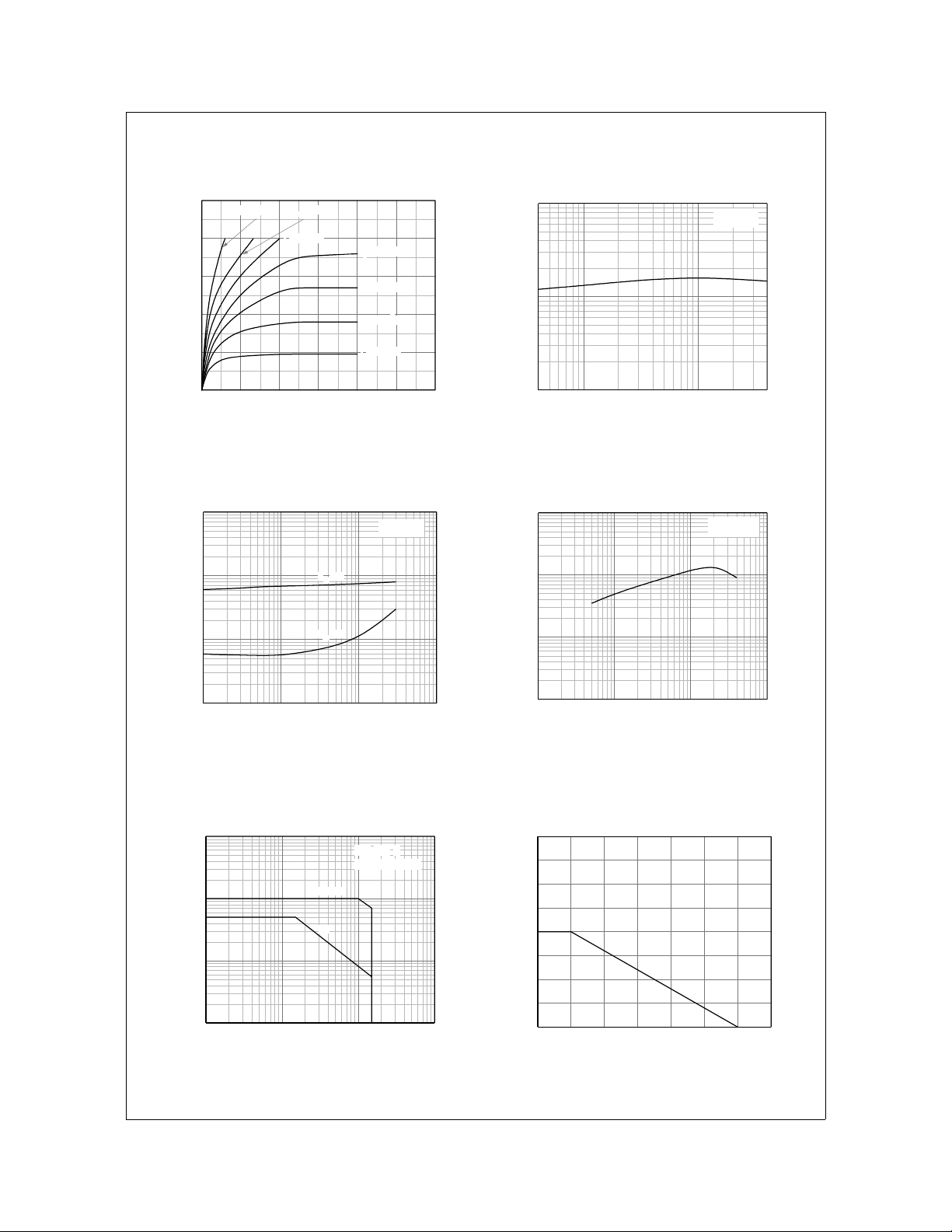
Typical Characteristics
KSC2310
50
IB = 1000µA
40
IB = 500µA
IB = 400µA
IB = 300µA
30
20
[mA], COLLECTOR CURRENT
10
C
I
0
024681012
IB = 200µA
IB = 150µA
IB = 100µA
VCE[V], COLLECTOR-EMITTER VOLTAGE
Figure 1. Static Characteristic Figure 2. DC current Gain
10
1
0.1
(sat)[V], SATURATION VOL TA GE
CE
IC = 10 I
VBE(sat)
VCE(sat)
1000
VCE = 5V
100
, DC CURRENT GAIN
FE
h
10
110
IC[mA], COLLECTOR CURRENT
1000
B
100
10
VCE = 30V
(sat), V
BE
V
0.01
0.1 1 10 100
IC[mA], COLLECTOR CURRENT
Figure 3. Base-Emitter Saturation Voltage
Collector-Emitter Saturation Voltage
1000
100
10
[mA], COLLECTOR CURRENT
C
I
1
1 10 100 1000
VCE[V], COLLECTOR-EMITTER VOLTAGE
1. Ta=25oC
2. *Single Pulse
*300ms
DC
Figure 5. Safe Operating Area Figure 6. Power Derating
1
0.1 1 10 100
[MHz], CURRENT GAIN BANDWIDTH PRODUCT
T
f
IC[mA], COLLECTOR CURRENT
Figure 4. Current Gain Bandwidth Product
1.6
1.4
1.2
1.0
0.8
0.6
0.4
[W], POWER DISSIPATION
C
P
0.2
0.0
25 50 75 100 125 150 175
0
Ta[oC], AMIBIENT TEMPERATURE
©2002 Fairchild Semiconductor Corporation
Rev. A2, September 2002
 Loading...