


Fairchild Semiconductor KSC2001 Datasheet
General Purpose Applications
• High hFE and Low V
CE
(sat)
KSC2001
KSC2001
1
TO-92
1. Emitter 2. Collector 3. Base
NPN Epitaxial Silicon Transistor
Absolute Maximum Ratings
Symbol Parameter Value Units
V
V
V
I
I
P
T
T
CBO
CEO
EBO
C
B
C
J
STG
Collector-Base Voltage 30 V
Collector-Emitter Voltage 25 V
Emitter-Base Voltage 5 V
Collector Current 700 mA
Base Current 150 mA
Collector Power Dissipation 600 mW
Junction Temperature 150 °C
Storage Temperature -55 ~ 150 °C
Electrical Characteristics
Symbol Parameter Tes t Condition Min. Typ. Max. Units
V
(on) * Base Emitter On Voltage VCE=6V, IC=10mA 600 640 700 mV
BE
I
CBO
I
EBO
h
FE1
h
FE2
(sat) * Collector-Emitter Saturation Voltage IC=700mA, IB=70mA 0.2 0.6 V
V
CE
(sat) * Base-Emitter Saturation Voltage IC=700mA, IB=70mA 0.95 1.2 V
V
BE
C
ob
f
T
* Pulse test: PW≤350µs, Duty cycle≤2%
Collector Cut-off Current VCB=30V, IE=0 100 nA
Emitter Cut-off Current VEB=5V, IC=0 100 nA
* DC Current Gain VCE=1V, IC=100mA
Output Capacitance VCB=6V, IE=0, f=1MHz 13 25 pF
Current Gain Bandwidth Product VCE=6V, IC=10mA 50 170 MHz
Ta=25°C unless otherwise noted
Ta=25°C unless otherwise noted
V
=1V, IC=700mA
CE
90
50
200
140
400
hFE Classification
Classification O Y G
h
FE1
©2002 Fairchild Semiconductor Corporation Rev. A2, September 2002
90 ~ 180 135 ~ 270 200 ~ 400
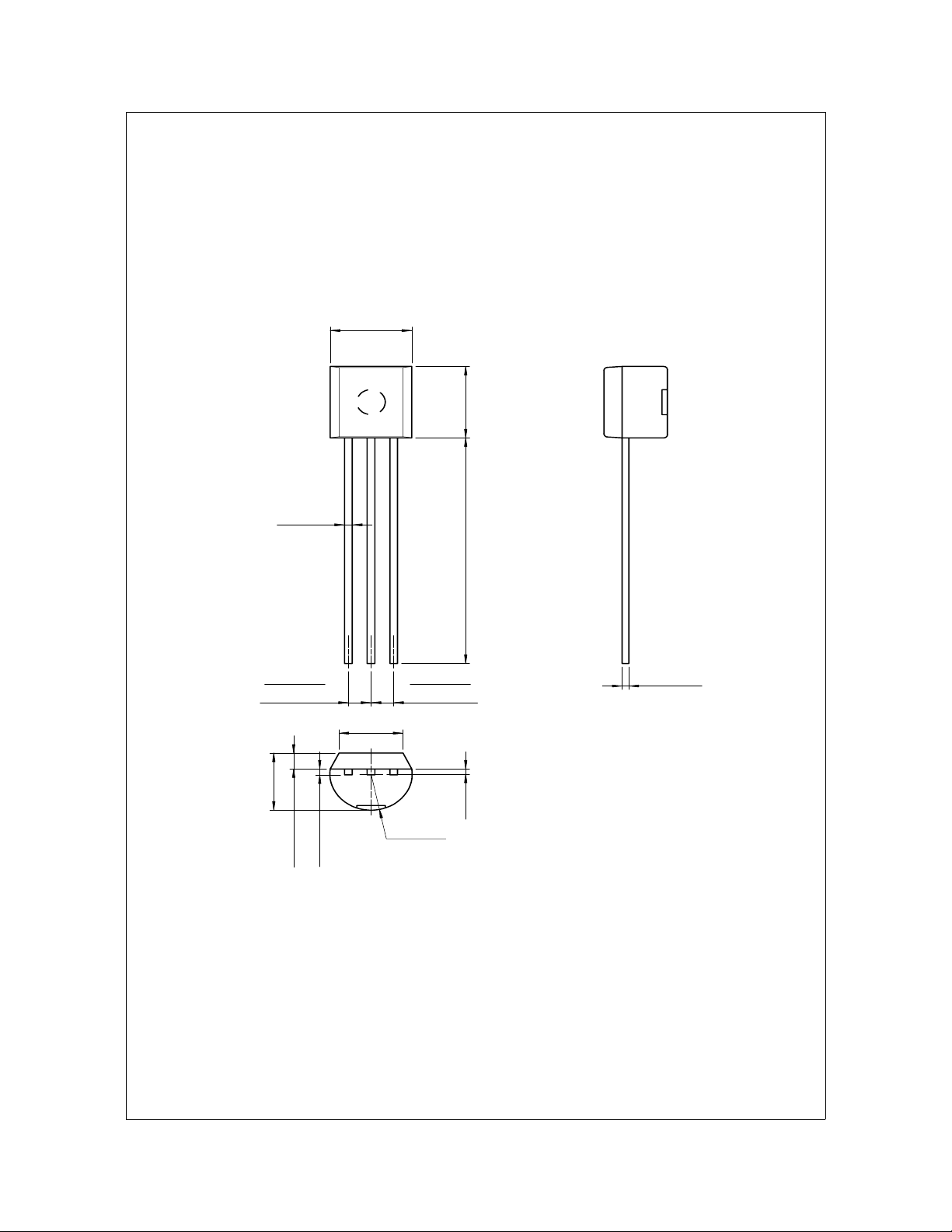
Package Dimensions
0.46
±0.10
4.58
+0.25
–0.15
KSC2001
TO-92
±0.20
4.58
±0.40
1.27TYP
[1.27
±0.20
3.86MAX
±0.10
1.02
+0.10
–0.05
0.38
14.47
1.27TYP
]
3.60
±0.20
[1.27
±0.20
]
0.38
+0.10
–0.05
(0.25)
(R2.29)
Dimensions in Millimeters
©2002 Fairchild Semiconductor Corporation Rev. A2, September 2002