

Fairchild Semiconductor KSA708 Datasheet
KSA708
Low Frequency Amplifier & Medium Speed
Switching
• Complement to KSC1008
• Collector-Base Voltage : V
• Collector Power Dissipation : P
• Suffix “-C” means Center Collector (1. Emitter 2. Collector 3. Base)
PNP Epitaxial Silicon Transistor
CBO
= -80V
=800mW
C
1
1. Emitter 2. Base 3. Collector
TO-92
KSA708
Absolute Maximum Ratings
Symbol Parameter Ratings Units
V
V
V
I
P
T
T
CBO
CEO
EBO
C
C
J
STG
Collector-Base Voltage -80 V
Collector-Emitter Voltage -60 V
Emitter-Base Voltage -8 V
Collector Current -700 mA
Collector Power Dissipation 800 mW
Junction Temperature 150 °C
Storage Temperature -55 ~ 150 °C
Electrical Characteristics
Symbol Parameter Tes t Condition Min. Typ. Max. Units
BV
CBO
BV
CEO
BV
EBO
I
CBO
I
EBO
h
FE
(sat) * Collector-Emitter Saturation Voltage IC= -500mA, IB= -50mA -0.3 -0.7 V
V
CE
(sat) * Base-Emitter Saturation Voltage IC= -500mA, IB= -50mA -0.9 1.1 V
V
BE
f
T
C
ob
* Pulse Test: PW≤350µs, Duty cycle≤2%
Collector-Base Breakdown Voltage IC= -100µA, IE=0 -80 V
Collector-Emitter Breakdown Voltage IC= -10mA, IB=0 -60 V
Emitter-Base Breakdown Voltage IE= -100µA, IC=0 -8 V
Collector Cut-off Current VCB= -60V , IE=0 -0.1 µA
Emitter Cut-off Current VEB= -5V, IC=0 -0.1 µA
* DC Current Gain VCE= -2V, IC= -50mA 40 240
Current Gain Bandwidth Product VCE= -10V , IC= -50mA 50 MHz
Output Capacitance VCB= -10V , IE=0, f=1MHz 13 pF
Ta=25°C unless otherwise noted
Ta=25°C unless otherwise noted
hFE Classification
Classification R O Y
h
FE
©2001 Fairchild Semiconductor Corporation Rev. A1, August 2001
40 ~ 80 70 ~ 140 120 ~ 240
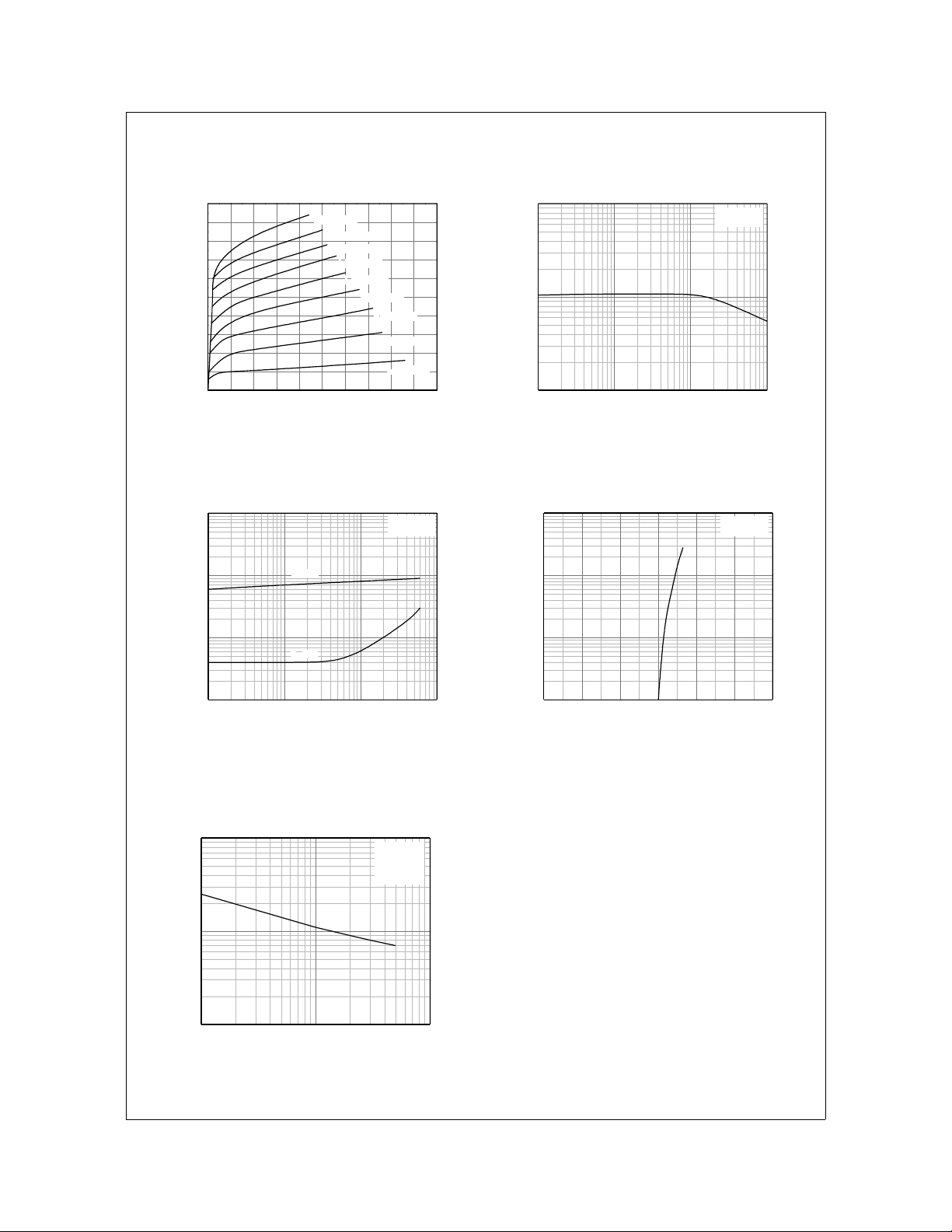
Typical Characteristics
KSA708
-500
-450
-400
-350
-300
-250
-200
-150
-100
[mA], COLLECTOR CURRENT
C
I
-50
0
0 -5 -10 -15 -20 -25 -30 -35 -40 -45 -50
IB = -1.8mA
IB = -1.6mA
IB = -1.4mA
IB = -1.2mA
IB = -1.0mA
VCE[V], COLLECTOR-EMITTER VOLTAGE
Figure 1. Static Characteristic Figure 2. DC current Gain
-10
-1
-0.1
(sat)[V], SATURATION VOLTAGE
CE
(sat), V
BE
V
-0.01
-1 -10 -100 -1000
IC[mA], COLLECTOR CURRENT
VBE(sat)
VCE(sat)
IB = -0.8mA
IB = -0.6mA
IB = -0.4mA
IB = -0.2mA
IC = 10 I
1000
VCE = -2V
100
, DC CURRENT GAIN
FE
h
10
-1 -10 -100 -1000
IC[mA], COLLECTOR CURRENT
B
-1000
-100
-10
[mA], COLLECTOR CURRENT
C
I
-1
0.0 -0.2 -0.4 -0.6 -0.8 -1.0 -1.2
VCE = -2V
VBE[V], BASE-EMITTER VOLTAGE
Figure 3. Base-Emitter Saturation Voltage
Collector-Emitter Saturation Voltage
100
10
Cob [pF], CAPACITANCE
1
-1 -10 -100
VCB [V], COLLECTOR-BASE VOLTAGE
Figure 5. Collector Output Capacitance
©2001 Fairchild Semiconductor Corporation
Figure 4. Base-Emitter On Voltage
IE = 0
f = 1MHz
Rev. A1, August 2001
 Loading...