

Fairchild Semiconductor DM9324N Datasheet
October 1988
Revised February 2000
DM9324
5-Bit Comparator
General Description
The DM9324 expandable comparators provide comparison
between two 5-bit words and give three outputs—“less
than”, “greater than” and “equal to”. A HIGH on the active
LOW Enable Input forces all three outputs LOW.
Ordering Code:
Order Number Package Number Package Description
DM9324N N16E 16-Lead Plastic Dual-In-Line Package (PDIP), JEDEC MS-001, 0.300 Wide
DM9324 5-Bit Comparator
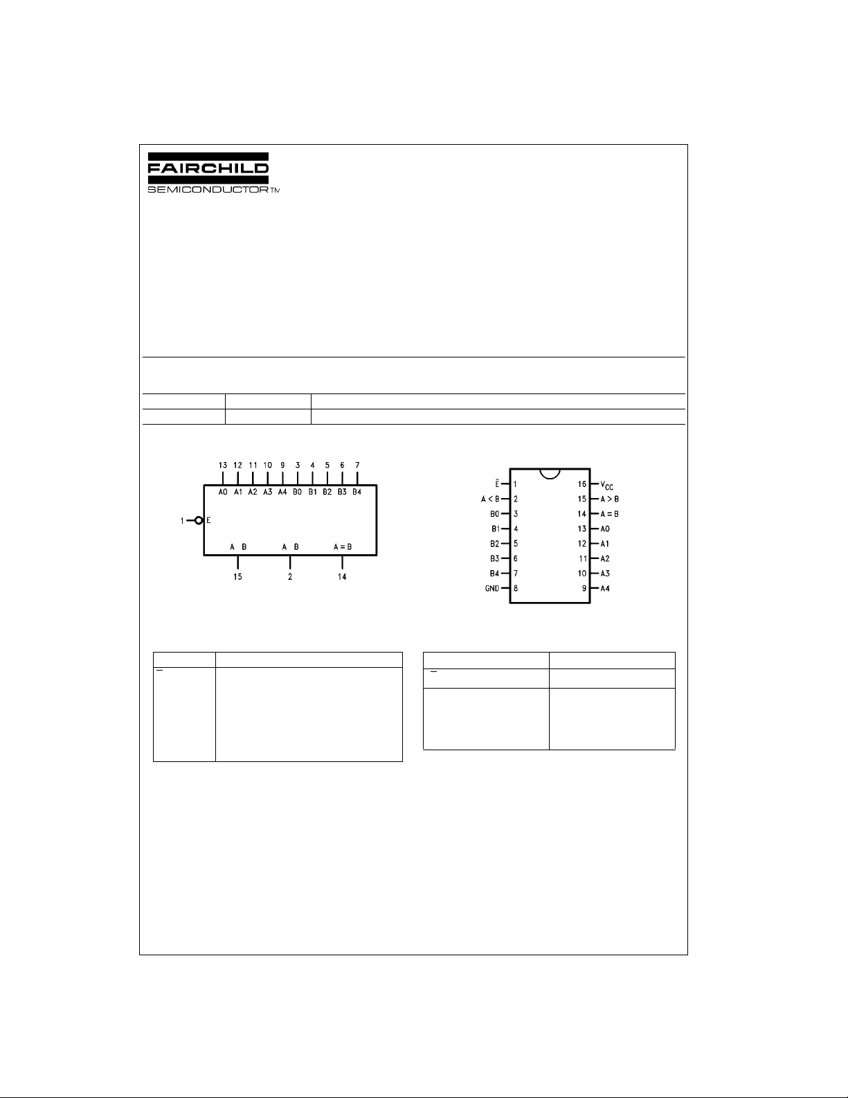
Logic Symbol
VCC = Pin 16
GND = Pin 6
Pin Descriptions
Pin Names Description
E
A0–A4 Word A Parallel Inputs
B0–B4 Word B Parallel Inputs
A < B A Less than B Output (Active HIGH)
A > B A Greater than B Output (Active HIGH)
A = B A Equal to B Output (Active HIGH)
Enable Input (Active LOW)
Connection Diagram
Truth Table
Inputs Outputs
A
E
HX X LL L
LWord A = Word B L L H
LWord A > Word B L H L
LWord B > Word A H L L
H = HIGH Voltage Level
L = LOW Voltage Level
X = Immaterial
n
B
A < BA > B A = B
n
© 2000 Fairchild Semiconductor Corporation DS009792 www.fairchildsemi.com
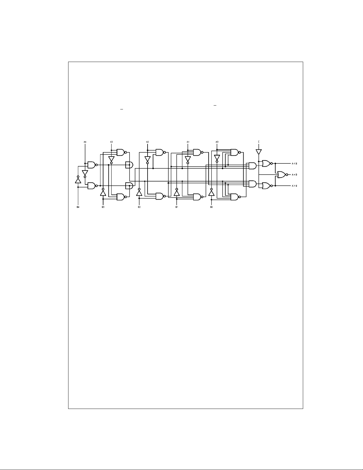
Functional Description
The ’24 5-bit comparators use combinational circuitry to
directly generate “A greater than B” and “A less than B”
DM9324
outputs. As evident from the logic diagram, these outputs
are generated in on ly three gate dela ys. The “A equals B”
output is generated in one additional gate delay by decoding the “A neither less than nor greater th an B” condition
with a NOR gate. All three outputs are activated by the
active LOW Enable Input (E
).
Logic Diagram
Tyi n g t he A > B output from one device into an A input on
another device and the A < B output into the corresponding
B input permits easy expansion.
The A4 and B4 inputs are the most significant inputs and
A0, B0 the least significant. Thus if A4 is HIGH and B4 is
LOW, the A > B output will be HIGH regardless of all other
inputs except E
.
www.fairchildsemi.com 2
 Loading...