

Page 1
Page 2
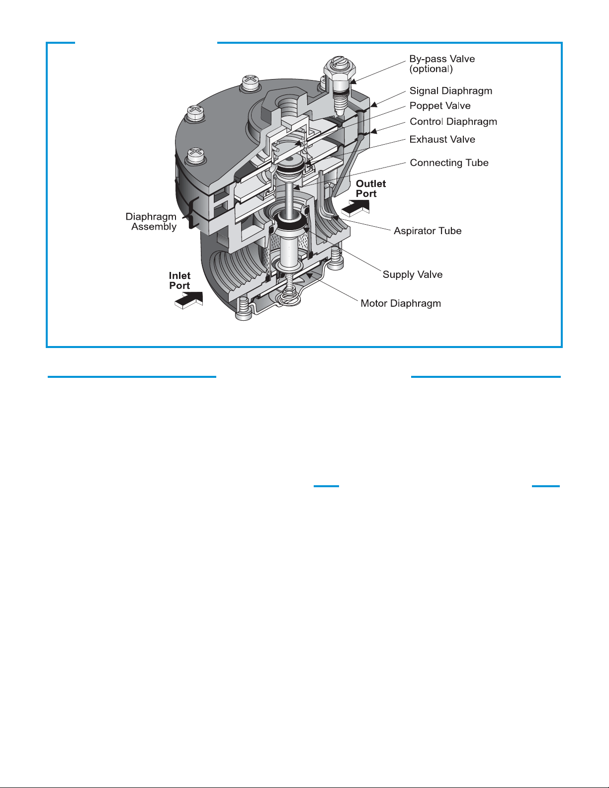
CROSS SECTION
Figure 1. Model 4500A Detail Drawing
GENERAL INFORMATION
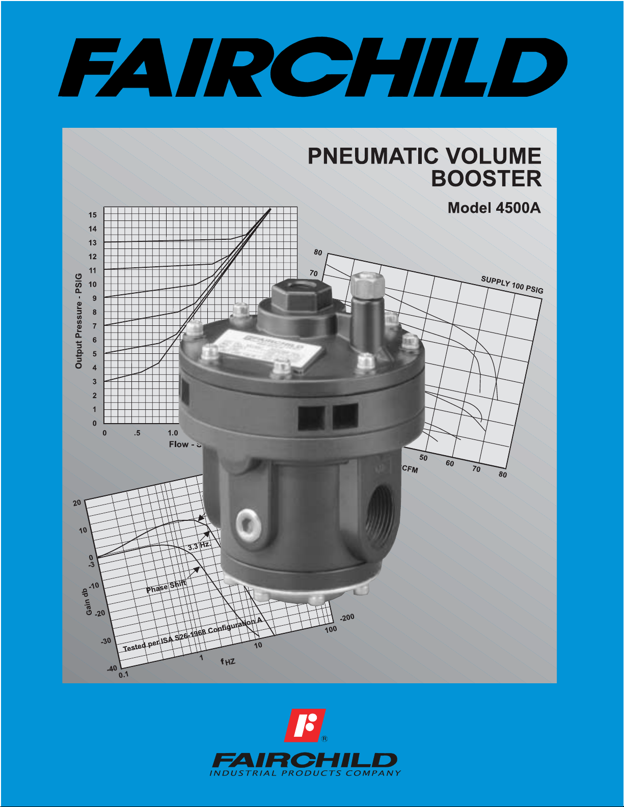
The Model 4500A Pneumatic Volume Booster reproduces a pneumatic signal in a 1:1 ratio or in multiplying
or dividing ratios. It is ideal for systems requiring input
isolation or increased flow capacity.
The Model 4500A has the following features:
Five (5) signal to output ratios meet most control element
•
requirements.
Control sensitivity of 1" water column allows use in
•
precision applications.
Large Supply and Exhaust V alves provide high forward
•
and exhaust flows.
Soft Supply and Exhaust Valve seats minimize air con-
•
sumption.
A balanced Supply Valve minimizes the effect of supply
•
pressure variation.
An Aspirator Tube compensates downstream pressure
•
droop under flow conditions.
A separate Control Chamber isolates the diaphragm
•
from the main flow to eliminate hunting and buzzing.
Optional remote feedback port minimizes pressure drop
•
at final control element under flow conditions.
1 Model 4500A
The optional adjustable By-pass Valve lets you tune for
•
optimum dynamic response. (1:1 Ratio Only)
Unit construction lets you service the Model 4500A without
•
removing it from the line.
OPERATING PRINCIPLES
When signal pressure on the top of the Signal Diaphragm creates a downward force on the Diaphragm
Assembly , the Supply Valve opens. Output pressure
flows through the Outlet Port and the Aspirator Tube
to the Control Chamber to create an upward force on
the bottom of the Control Diaphragm. When the
setpoint is reached, the force of the signal pressure
that acts on the top of the Signal Diaphragm balances
with the force of the output pressure that acts on the
bottom of the Control Diaphragm to close the Supply
Valve.
When the output pressure increases above the signal pressure, the Diaphragm Assembly moves upward to close the Supply V alve and open the Exhaust
V alve. Because the Poppet V alve is closed, pressure
flows down the Connecting Tube to the bottom of the
Motor Diaphragm. This pressure keeps the Supply
Valve tightly closed while in the exhaust mode. The
Poppet Valve opens and excess output pressure
exhausts through the vent in the side of the unit until
it reaches the setpoint. For more information, see
Figure 1.
Page 3

3/8
9.5
5/16
8.1
By-pass Valve
1:1 Ratio Only
(optional)
1/4 NPT
Signal Port
43/64
20.4
31/64
12.2
By-pass
Valve Open
By-pass
Valve Closed
OUTLINE DIMENSIONS
Hex.
1
25.4
1 13/32
35.9
1/2 NPT Tapped
Exhaust Port
(optional)
5 5/64
128.8
3 19/64
83.8
3/8 NPT
Inlet Port
3 1/2
Face Dim.
88.9
(typical)
3 13/32
86.6
FUNCTIONAL SPECIFICA TIONS
Maximum
Output
Pressure
Maximum
Supply
Pressure
Ratio
[BAR]
(kPa)
[BAR]
(kPa)
1:1 1:2 1:3
psig
150
[10.0]
(1000)
psig
250
[17.0]
(1700)
(1000)
(1700)
Flow Capacity
100 psig, [7.0 BAR],
(700kPa) supply,
SCFM
150
20 psig, [1.5 BAR],
(150 kPa) set point.
(m3/HR)
(255)
Exhaust
Vents (8)
(keep clear)
1/8 NPT
Remote
Feedback
Port
(optional)
3/8 NPT
Outlet Port
(typical)
1/4 NPT
Gage Ports (2)
(typical)
2 19/64
58.5
1 9/16
39.6
Figure 2. Model 4500A Outline Dimensions
SPECIFICATIONS
PERFORMANCE SPECIFICATIONS
2:1
3:1
150
[10.0]
250
[17.0]
150
(255)
150
[10.0]
(1000)
250
[17.0]
(1700)
150
(255)
75
[5.0]
(500)
250
[17.0]
(1700)
150
(255)
50
[3.5]
(350)
250
[17.0]
(1700)
150
(76.5)
Sensitivity
Water Column
Ratio Accuracy
% of 100 psig, [7.0 BAR],
(700 kPa) output span.
% of output span with
100 psig, [7.0 BAR],
(700kPa) input span.
Supply
Pressure Effect
for change of 100 psig
[7.0 BAR], (700 kPa).
Ratio
(cm)
psig
[BAR]
(kPa)
4 1/2
114.3
1:1 1:2 1:3
1"
2"
(2.54)
(5.08)
3.0 3.0 3.0
0.10
0.20
[.007]
[.014]
(0.7)
(1.4)
3"
(7.62)
0.30
[.021]
(2.1)
5 53/64
148.2
2 53/64
71.8
2:1
2"
(5.08)
3.0 3.0
0.10
[.007]
(0.7)
3:1
2"
(5.08)
0.10
[.007]
(0.7)
Exhaust Capacity
Downstream Pressure
5 psig, [.35 BAR],
(35 kPa) above
20 psig, [1.5 BAR],
(150 kPa) set point.
SCFM
(m3/HR)
40
(65.2)
40
(65.2)
40
(65.2)
40
(65.2)
40
(18.7)
Ambient
Temperature
Materials
of Construction
Body & Housing . . . . . . . . . . . . . . . . . .
Trim . . . . . . . . . . . . . . . .
Diaphragm . . . . . . . . . . . . . . . .
-40
-0
F to 200
-0
F
(-400C to 93.30C)
Aluminum
Zinc Plated Steel, Brass
Nitrile on Dacron
Model 4500A 2
Page 4

TYPICALAPPLICATION
1
4
E
VRG CONTROLS USE MODEL 4514AE
x
x
x
4-20 mA
120 psig,
[8.0 BAR],
(800 kPa)
Supply
Pneumatic
Electrical
Controller
4-20 mA Feedback
Model
T8000
30 psig, [2.0 BAR], (200 kPa) or
50 psig, [3.5 BAR], (350 kPa)
Model
T6000
Tire
B
Model
4516A
Figure 3. Model 4500A Inflation and Test Pressure Application
TYPICAL APPLICATION
The Model 4500A controls inflation and test pressures of a tire testing machine. An electronic controller transmits a 4-20 mA signal to a TA6000-405
transducer. The transducer sends an output signal
to a Model 4516A Booster. The booster provides a
set pressure to set the tire on the bead. The booster
also reduces and maintains the pressure during
testing. The T8000 senses the tire pressure and
sends a 4-20mA signal to the Controller to close the
loop. For more information, see Figure 3.
INST ALLA TION
For installation instructions, see the Model 4500A Pneumatic Volume Booster IOM, IS-2004500A.
ORDERING INFORMATION
ORDERING INFORMATION
Catalog Number
Ratio
1:1
1:2
1:3
2:1
3:1
Pipe Size
3/8 NPT
1/2 NPT
3/4 NPT
Options
T apped Exhaust
By-pass V alve
Feedback
BSPT(T apered)
BSPP (Parallel)
1
For 1:1 Ratio Only.
2
BSPP Threads in Inlet & Outlet. Others BSPT.
1
2
45
(1)
(2)
(3)
(4)
(5)
A
(3)
(4)
(6)
(E)
(I)
(P)
(U)
(H)
CS-2004500A
Litho in USA
Rev. B 11/02
 Loading...