


Fagor Automation S. Coop.
Manual code: 14460053
Manual version: 0703
Software version: 4.xx
20i-M / 30i-M
20i-M B / 30i-M B
Installation/Operation Manual

INDEX
1 DRO description ..........................................................................................3
1.1 Front panel ........................................................................................................................ 3
1.2 Turning the unit on and off .............................................................................................. 4
2 DRO operation .............................................................................................5
2.1 Display modes .................................................................................................................. 5
2.2 Incremental, absolute and with respect to Machine Reference Zero .......................... 6
2.2.1 Example .............................................................................................................................. 7
2.2.1.1 Absolute mode .................................................................................................................... 7
2.2.1.2 Incremental mode ............................................................................................................... 8
2.3 Machine Reference selection and search ...................................................................... 9
2.3.1 Home search sequence: .....................................................................................................9
2.4 Operating with tools ....................................................................................................... 10
2.4.1 Entering tool dimensions ..................................................................................................10
2.4.2 Tool dimension compensation while machining ............................................................... 10
2.4.3 Datum point (part zero) to work with tool compensation .................................................. 10
2.5 Special operations.......................................................................................................... 11
2.5.1 Scaling factor .................................................................................................................... 11
2.5.2 Part centering ................................................................................................................... 12
2.6 Examples of how to operate with tool compensation ................................................. 12
2.6.1 Inside pocket .................................................................................................................... 12
2.6.2 Outside pocket .................................................................................................................. 13
2.7 Access to special modes ............................................................................................... 14
2.7.1 Linear and bolt-hole drilling .............................................................................................. 15
2.7.1.1 Work plane selection: ....................................................................................................... 15
2.7.1.2 Bolt-hole drilling ................................................................................................................ 15
2.7.1.3 Execution of bolt-hole drilling ............................................................................................ 16
2.7.1.4 Linear drilling .................................................................................................................... 17
2.7.2 Coordinate freeze (HOLD). ............................................................................................... 17
2.7.3 Calculator ......................................................................................................................... 18
2.7.3.1 Operating with the calculator. ........................................................................................... 18
2.7.3.2 Recall and Reset modes ..................................................................................................19
2.7.4 Part angle measuring ....................................................................................................... 20
2.7.5 Corner rounding ................................................................................................................ 21
3 DRO installation ........................................................................................22
3.1 Installation of the built-in model ................................................................................... 22
3.2 Rear panel ....................................................................................................................... 23
3.3 General technical characteristics ................................................................................. 24
3.4 Connections .................................................................................................................... 24
3.4.1 Connection of the feedback systems ................................................................................ 24
3.5 Easy setup....................................................................................................................... 25
3.5.1 Accessing the "Easy Setup" mode ................................................................................... 25
3.5.2 Operating mode. ............................................................................................................... 25
3.5.3 Power and machine connection ....................................................................................... 26
3.6 Installation parameters .................................................................................................. 26
3.7 Parameters to configure axis position reading and display....................................... 28
4 Appendix ....................................................................................................35
4.1 UL seal............................................................................................................................. 35
4.2 CE seal............................................................................................................................. 35
4.2.1 Declaration of conformity .................................................................................................. 35
4.2.2 Safety conditions .............................................................................................................. 36
4.2.3 Warranty terms ................................................................................................................. 38
4.2.4 Material returning terms .................................................................................................... 38
4.3 Error codes ..................................................................................................................... 39
4.4 Maintenance .................................................................................................................... 40
(2/40) - Installation/Operation - 20i-M / 30i-M - V0703
1.1 Front panel
Each axis display has eight 14.1mm high LEDs and another one for the minus
sign (-).
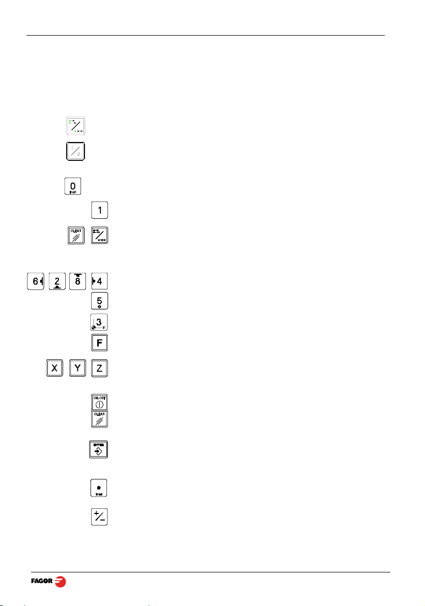
Description of LED's and keys:
ABS It stays on when operating in absolute mode and off when in incremental
mode. To access it or quit it, press this key.
Φ It stays on when operating in diameter mode. In this mode, the DRO displays
twice the actual axis movement. To access it or quit it, use this key if allowed
by installation parameter PAR04.
INCH It stays on when working in inches and off when doing it in millimeters. To
access it or quit it, press this key.
This key toggles the display format for the rotary axis [PAR00(4)=1] between
decimal degrees and Degrees.Minutes.Seconds.
To get into and out of home search mode.
TOOL It stays on when operating in tool radius compensation mode.
Activate tool radius compensation.
Cancel tool radius compensation.
Select the current reference.
To access the special functions (bolt-hole and linear drilling, hold, calculator,
part angle, corner rounding).
To select the axis or preset it with a certain value.
To zero the axis when the "quick zeroing" mode has been activated (see
PAR11 in the installation manual).
To turn the display off while keeping track of the axes position at all times.
To cancel or abort an operation already initiated.
1 DRO description
To validate a preset value or another operation.
Beginning of preset when the "quick zeroing" mode has been activated (see
PAR11 in the installation manual).
Editing the tool diameter
To change the sign of the entered value or change from fine to coarse
resolution and vice versa.
V0703 - 20i-M / 30i-M - Installation/Operation - DRO description - (3/40)

1.2 Turning the unit on and off
It turns on automatically when applying voltage or after pressing the on/off
key.
It shows Fagor dro or the corresponding error code. See the error table and
PAR11 for more options.
Turns the DRO on or off.
Precautions
Before disconnecting this unit from mains, press this key so it saves the
current position.
If the unit is turned off or there is a power outage, the DRO will try to save the
current position. If it does not have enough time to safe all the data, it will
display ERROR 2 when turned back on.
(4/40) - DRO description - Installation/Operation - 20i-M / 30i-M - V0703
2.1 Display modes
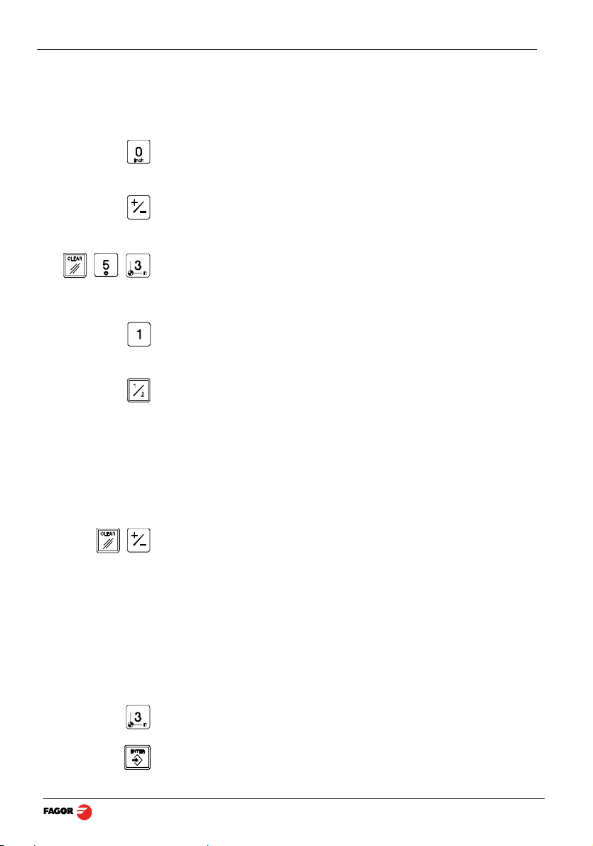
MM / INCH conversion
To display the position of the axes either in millimeters or inches by pressing
this key depending on whether the INCH led is off or on respectively.
Fine / coarse resolution
To turn off the last decimal digit (coarse resolution) for cases in which fine
resolution is excessive, simply by pressing this key.
Number of decimals
This keystroke sequence accesses parameter PAR53. The first digit
corresponds to the number of decimals to be displayed in mm and the second
digit in inches.
Decimal degrees / Degrees.Minutes.Seconds
This key toggles the display format for the rotary axis [PAR00(4)=1] between
decimal degrees and Degrees.Minutes.Seconds.
Radius / Diameter
When these models are used for measuring radii or diameters, one can
display twice the real displacement of the axis (diameter) by pressing this key.
The Φled will turn on or off to indicate the double or actual reading
respectively.
Notes: - This works in this way if bit 2 of installation parameter PAR04
(radius/diameter) of the axis has been preset as “1” (commutated).
Hysteresis or minimum position value
When carrying out certain operations such as drilling hard material, EDM, etc.
the position display may fluctuate annoyingly.
In these cases, the operator can eliminate this oscillation by selecting the
"hysteresis" mode or the "minimum coordinate" mode just by pressing this
keystroke sequence to toggle from one mode to the other.
Note: To have this option available, installation parameters PAR20 and PAR25
must be set accordingly.
Part references (datum points)
There are 20 references or datum points that may be set for the part when
using absolute coordinates. The possible reference points (datum points) are
from 0 to 19. The 20i-M model shows the active reference on the display at all
times, whereas the 30i-M model only shows it when it is selected, after
pressing the reference key.
Selects the current reference. It will show the text "Select ref".
2 DRO operation
[Ref number]
Key in the desired reference number and press [ENTER].
V0703 - 20i-M / 30i-M - Installation/Operation - DRO operation - (5/40)
2.2 Incremental, absolute and with respect to Machine Reference Zero
A coordinate DRO displays the present coordinate of one or several axes.
Coordinate means the distance from one point or position with respect with
another chosen as reference.
These DROs can display the position of the axes in incremental or absolute
mode or referring to home.
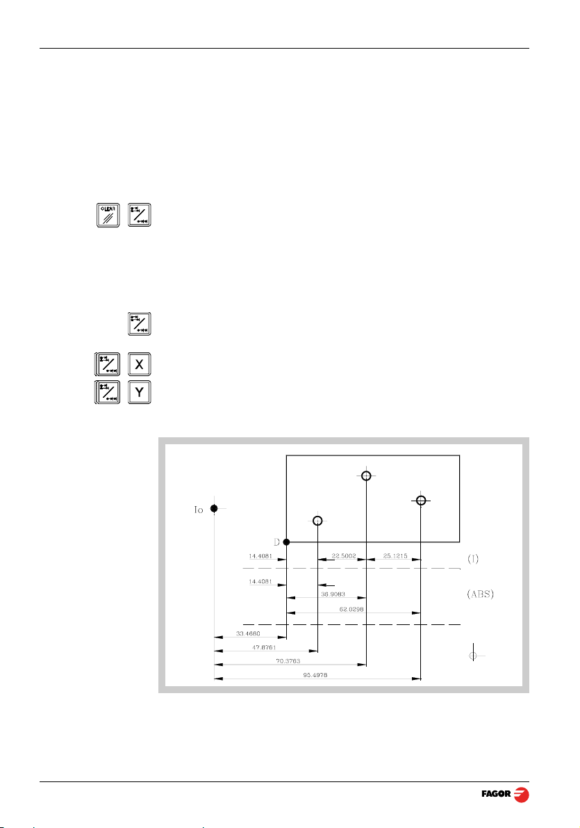
The next figure shows the different position display modes:
•In Home mode, it displays the distance from the current position of the axis
to the home point chosen in the feedback system (linear or encoder).
Press this sequence to access the Home Search mode.
(ABS) •In Absolute (ABS), when the ABS led is on , it displays the distance from
the present position of the axis to part zero (D).
(I) •In Incremental, when the ABS and "home" LEDs are off the distance from
the present position of the axis to the previous position is displayed.
Toggles between the ABS and incremental modes.
It could occur that the installation parameter PAR11(1) has been set to “0” for
this key to independently affect each axis so that one axis can display its
position in incremental mode while the other does this in absolute. In this
case, to change the display mode for a particular axis, press one of these two
sequences.
(6/40) - DRO operation - Installation/Operation - 20i-M / 30i-M - V0703

2.2.1 Example
We will drill the holes of the following part as moving examples in incremental
and absolute modes.
First, set the datum point on the part to be machined as described in the
section Datum point (part zero) to work with tool compensation
The axis must be positioned without tool compensation (canceled) because
the hole coordinates are referred to the center and no tool radius
compensation is needed.
2.2.1.1 Absolute mode
ABS
Set the dro in absolute mode
A
B
C
D
(B) [14.000]
(C) [37.000]
(D) [62.000]
Move the axis until the display reads [14.000] (B position) and drill the hole.
Move the axis until the display reads [37,000] (C position) and drill the hole.
Move the axis until the display reads [62,000] (D position) and drill the hole.
The displayed position value is always referred to the preset part zero
(datum).
V0703 - 20i-M / 30i-M - Installation/Operation - DRO operation - (7/40)

2.2.1.2 Incremental mode
“ABS” off
Set the dro in incremental mode. ABS LED off
First method: Presetting incremental zero after each drill.
Starting at point A.
(B) [14.000]
Move the axis until the display reads [14.000] (B position) and drill the hole.
Set the X axis to zero. See note.
(C) [23,000]
(D) [25,000]
Move the axis until the display reads [23,000] (C position) and drill the hole.
Sets the X axis to zero. See note.
Move the axis until the display reads [25,000] (D position) and drill the hole.
Note: If installation parameter PAR11=1, just press the axis key, ([X]) in this case, to
zero the axis.
Second method: Presetting the relative distance with respect to the next hole.
Starting at point A
-14
(B) [0.000]
-23
(C) 0.000
-25
(D) [0.000]
Preset the relative distance to the next hole. See note.
Move the axis until the display reads [0.000] (B position) and drill the hole.
Preset the relative distance to the next hole. See note.
Move the axis until the display reads [0.000] (C position) and drill the hole.
Preset the relative distance to the next hole. See note.
Move the axis until the display reads [0.000] (D position) and drill the hole.
Notes: If installation parameter PAR11=1, the presetting sequence is: [ENTER] [axis]
[value] [ENTER].
Switching over to [ABS] mode, displays the distance to part zero (datum).
The calculator function can also be used to preset an axis with the result of
the calculation. See section 2.7.3 Calculator.
(8/40) - DRO operation - Installation/Operation - 20i-M / 30i-M - V0703
2.3 Machine Reference selection and search
Although it is not absolutely necessary, it is recommended to use the
reference marks (Io) of the feedback system in order to set a machine zero
point.
This allows the user to reference the machine axes and restore the work
coordinates after having turned the dro off, moved the machine while the dro
was off, for safety or for any other reason.
Fagor linear encoders have reference marks every 50 mm all along its length.
In order to use these marks properly, choose an area on the axis, for example
in the middle of the measuring length or at one end. Approach this area and
carry out the home search. Once the reference mark has been found, mark
this area with a marker or sticker in order to carry out the home search in the
same area in later occasions and make sure that you are using the same
machine zero point (home).
Fagor also offers encoders with distance-coded reference marks every 20, 40
or 100 mm. When using these distance-coded reference marks, there is no
need to move to the 0 position to find the references, simply move a distance
equal to the gap between marks (20, 40 or 100 mm depending on the linear
encoder)
When using an absolute encoder, there is no need to search for the reference
marks (home).
The dro stores in its internal memory work coordinates such as machine zero,
absolute and incremental.
2.3.1 Home search sequence:
For encoders with regular reference marks, move the axis to the home area.
Access or exit the home search mode.
The axis displays blink showing " r " if the axis has not been homed or
" r on" if it has been homed.
Select the axis to be referenced (homed)
The selected axis blinks until a reference mark is detected. The reference
signal presets the axis display automatically with the value of PAR10, 0.000
mm by default.
If the encoder does not have a reference mark, move the axis to the desired
position and press this key.
V0703 - 20i-M / 30i-M - Installation/Operation - DRO operation - (9/40)

2.4 Operating with tools
It is possible to define a tool and later compensate for its dimensions while
machining.
2.4.1 Entering tool dimensions
The Y axis blinks waiting for the tool value to be entered.
20i-M.- It requests the tool diameter.
30i-M.- It requests the diameter on the Y axis and the length on the Z axis.
[Value]
2.4.2 Tool dimension compensation while machining
Enter this value pressing this keystroke sequence.
Note: Since only the diameter of a tool may be stored, when changing a tool, its
dimensions must be entered again.
To properly machine the part, the tool diameter must be compensated
depending on the machining direction.
Z
Y
X
Too l This led turns on when activating any of the compensations.
Cancels tool compensation and turns the Tool led off.
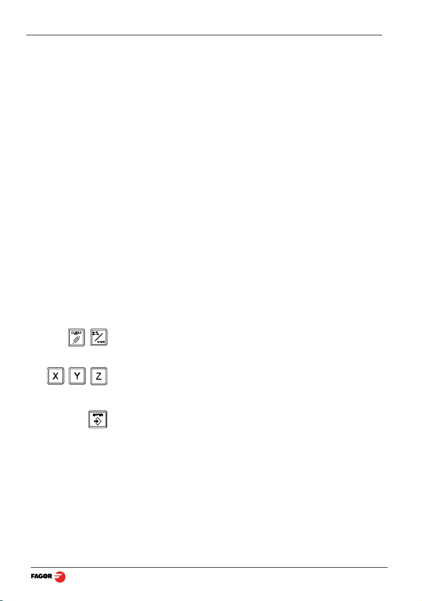
2.4.3 Datum point (part zero) to work with tool compensation
ABS
(10/40) - DRO operation - Installation/Operation - 20i-M / 30i-M - V0703
Set the dro in absolute mode.
Move the tool and touch the side of the part, activate the corresponding
compensation and set the axis to zero.

X
In the example of the figure, the sequence would be:
For the X axis, move the tool and touch it on the left side and press this key.
To preset this side to “0”. See note.
For the Y axis, move the tool and touch it on the lower side and press this key.
To preset this side to “0”. See note.
Y
Notes: If installation parameter PAR11=1, just press the axis key, [X] [Y] or [Z], to
zero it.
The tool diameter value must be previous entered in order to set the datum
(zero) point correctly.
2.5 Special operations
2.5.1 Scaling factor
It is possible to apply a scaling factor within ±9.999 for mold making
applications:
The DRO will then show the axis position resulting from multiplying its real
position by the 'value' of the scaling factor.
[factor]
V0703 - 20i-M / 30i-M - Installation/Operation - DRO operation - (11/40)

2.5.2 Part centering
Note: This feature is available when none of the axes have installation
parameter PAR04(2)=1 (radius/diameter commutable).
Part centering can be done as follows:
- Set the dro in absolute mode.
- Touch one side of the part with the tool.
- Set the reading to zero pressing for an axis [CLEAR] [X] for one axis or
[CLEAR] [Y] for the other one.
- Take the tool to the other side of the part and touch this with it.
- Press the sequence [1/2] [X] for one axis or [1/2] [Y] for the other. The DRO
will display half of the distance covered by the tool.
- Retract the axes until the displays read 0.0000, the tool can be placed
exactly at the center of the part.
2.6 Examples of how to operate with tool compensation
The following illustration displays the typical application of tool compensation
to make both an inside and outside pocket.
Tool compensation is applied by pressing either [6] , [4] , [8] or [2] and
canceled by pressing [5] .
After presetting the tool diameter, as was described in the previous section, it
is advisable to know how to apply the compensation before making said
movement.
2.6.1 Inside pocket
A
(12/40) - DRO operation - Installation/Operation - 20i-M / 30i-M - V0703
B
 Loading...