

Page 1
AD-21BDD
Instruction Manual
FAGOR GLASSWASHER WITH DRAIN PUMP AND
DETERGENT DISPENSER
Fagor Australasia Pty Ltd
7 Boola Place
Dee Why
NSW 2099
Phone: 02 9984 7533
Fax: 02 9984 7544
Email: info@fagor.com.au
Page 2
1. POSITIONING
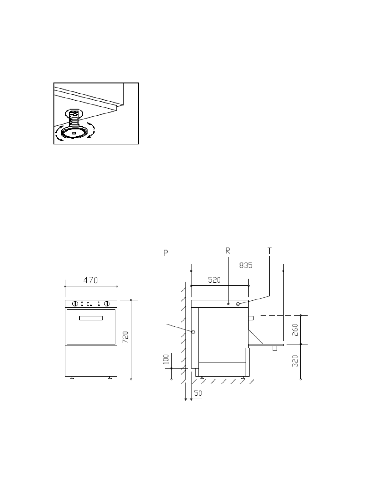
1.1 For the machine to work properly, you must ensure that it is level. Four
threaded bolts (legs) are supplied with your machine. These should be fitted to the
underside of the machine and adjusted to level the machine, as shown in Figure 1.
Figure 1
2. INSTALLATION
2.1 Connect the mains to the water supply, as shown in Figures 2 and 3. The
machine should be connected to a hot water supply of above 50°C but no more
than 60°C to allow the machine to operate efficiently. Inlet operating pressure is
400 kPa and maximum inlet supply temperature is 60°C.
2.2 If the pressure is more than 70 PSI, a pressure limiting valve should be fitted.
Figure 2
Page 3

A= Water inlet
D= Drain hose 25mm in diameter and must be installed in accordance with AS/NZS3500.2 (drainage) by means of
coupled connection to a DN40 or larger pipe.
E= Electric s. Cable
NOTE: must be installed in accordance with AS/NZS3500.1 (water
service supply) including installation of the supplied backflow
prevention device
Figure 3
S = Stopcock / F = Filter / H= Fagor supplied hose and backflow prevention device / E = Electrovalve /
B = Electropump / C= Drain collector / D= Drain hose
2.3 Dynamic pressure during rinse is 2÷4 Kg/cm2. If the pressure is less than 2
kg/cm2 (28 PSI), an electrical pressure pump should be installed, as shown in
Figure 4.
Page 4

Figure 4
S = Stopcock / F = Filter / H= Fagor supplied hose and backflow prevention device / E = Electrovalve / B
= Electropump / C= Drain collector / D= Drain hose
2.4 When the water hardness level is above 10º F, a water softener should be
installed.
2.5 A stopcock should be fitted below the machine’s water intake.
2.6 Fix the drain hose as shown in Figure 5 and fit a siphon pipe to prevent bad
smells. Please note the maximum height of the drain hose indicated on Figure 2.
Do not extend the length of the drain hose supplied with your machine.
Figure 5
A=Overflow / C=Drain collector / D=Drain hose / F =Filter
2.7 Connect the electrical connections, referring to Figures 2, 6 and 7.
2.8 For access to the connection strip (R), remove the cover (T) and the rear panel
(P).
Page 5

2.9 Fix the sheathed cable to (E), leaving enough cable to remove the electrical
panel from the front.
2.10 Connect the strip as shown in Figure 6.
2.11 Fit a general switch (I) independent of the appliance with a distance between
contact equal to or more than 3mm.
2.12 The machine must be earthed.
Figure 6
Figure 7
Figure 8: Technical Specifications of AD-21BDD
Model
Water
inlet
pressure
Supply
Voltage
Tank
Heating
Element
Boiler
Heating
Element
Max.
power
used
Basket
size
Cycle
duration
Tank
capacity
Rinse
water
consumed
Net
Weight
AD21B
DD
(200÷400
kPa)
(2÷4
Kg/cm2)
(28÷ 56
psi)
230-V-
1N
15 A 1
Phase
2 KW 2.8 KW
3.13
KW
400x400
mm
90”,
120”,
180”
15 litres
2,5
litres/rinse
39 KG
(220-240V-1N~)
am/ve=yellow-green
a= blue
m= brown
r= red
n= black
Page 6

3. USING YOUR AD-21 BDD GLASSWASHER WITH DRAIN PUMP AND
DETERGENT DISPENSER
3.1 Put the clear hose (located at the back of the machine), into a bottle of liquid,
non-foaming detergent. Make sure that the filter on the end of the pipe is fully
submerged and the pipe is not kinked.
3.2 Put the blue hose (located at the back of the machine), into a bottle of rinse aid.
Make sure that the filter on the ends of the pipe is fully submerged and the pipe is not
kinked.
3.3 Prepare crockery for washing by removing large bits of food before loading the
crockery into the baskets. Glassware should be washed first. Plates should not be
stacked on top of each other (see Figure 9). Cups and glasses should be washed
upside down. Cutlery should be washed in the yellow cutlery baskets with handles at
the bottom; each yellow basket should contain a mixture of spoons, forks and knives
for optimum washing conditions. The cutlery holders should be put into one of the
baskets.
Figure 9
3.4 Load the machine with a basket of dirty dishes/cutlery. Close the door and
press the switch button (1 on Figure 10) to turn machine on. Pilot light (2) will come
on and the boiler and wash tank will begin to fill up with water and heat up.
Figure 10
AD-21BDD
3.5 Wait for water to heat up to required temperature. The thermometer (9)
indicates the rinse temperature and the thermometer (10)indicates the wash
temperature. The machine is ready when the thermometer (9) indicates 85-90°C and
the thermometer (10) indicates 55-60°C. The glassw asher is fitted with a thermostop
to ensure a minimum rinse temperature of 85°C. The temperature of the incoming
water should be 50°C or more. Colder water may affect the machine’s performance.
Page 7

3.6 Press P1, P2 or P3 button to select the require length of the wash (90”, 120’’ or
180” respectively). The appropriate LED (4,6 & 8 on Figure 10) will light up.
3.7 When the cycle has finished, the LED will go off. The door can be opened and
the basket removed. Another basket of crockery can be inserted and button P1, P2 or
P3 pressed for another wash cycle to start. Never place a basket of washed dishes on
top of the machine; water could drip from the basket and damage the machine’s
electrical components.
3.8 The glasswasher drains automatically in each cycle. At the end of each day or
service, or as required, the glasswasher should be completely drained. See details
below:
Make sure the machine is
turned on.
1- Remove the upstand
(drain plug) by pulling it up
from inside the filter (See
photo and ‘A’ in Fig. 5).
2- Leave the door open and
press the button P1
for 5 seconds until the
green light flashes.
3- You will hear the pump
start to work and see the
drain out. When the pump
stops making a noise and
the water is drained out,
remove the suction filter (
‘F’ on Fig. 5) by turning it
anti-clockwise and pulling
out. Use soapy water to
clean the filter, ensuring
that all particles are
removed.
4- Replace suction filter and drainplug in machine. The machine is now ready to be
re-used or turned off, as appropriate.
Page 8

4.- MAINTENANCE
4.1 Check the detergent and rinse liquid containers on a daily basis to ensure
levels are sufficient and the filters on the ends of the pipes are fully submerged.
Check pipes leading from the containers for kinks.
4.2 Everyday, clean the suction filter (F on figure 5). To do this, remove the antioverflow device (drain plug) in the middle of the suction filter, turn (F) anticlockwise
and lift it up. Use soapy water for cleaning, not abrasive detergents. Never use jets of
water to clean the outside of the machine.
4.3 Check that all parts are securely fixed, in particular that the screws on the wash
and rinse arms have not worked loose.
4.4 If the machine is not going to be used for a long time, cover its surfaces with a
coating of petroleum jelly.
5 ELECTRICAL AND MECHANICAL PROBLEMS – (TROUBLESHOOTING)
The following should be checked before calling for technical service
5.1 If the machine has no power, check if it is plugged in to the power supply and
that the voltage coincides with that required by the machine.
5.2 If the machine has no power, check if the power cord is damaged, in which case
it should be replaced by the manufacturer or by its aftermarket service or by other
qualified personnel in order to prevent hazards.
5.3 If the water connection or the start up take too long check the water supply is
working at the required temperature and that the drain plug has been inserted.
5.4 If the machine is not rinsing or washing properly, check that the arms rotate
properly and the nozzles are not blocked. To remove the rise arm, unscrew the thumb
screw in the central support (using a coin). Wash the rinse arm in soapy water and
reposition. Tighten the screw.
5.5 If the machine is not washing or rinsing properly, check the levels of rinse aid
and detergent and check that the supply pipes are not kinked and do not have an air
bubble blocking them.
5.6 After sales service:
Fagor Australasia Pty. Ltd., 7 Boola Place, Dee Why, NSW.
Tel. 02 9984 7533
Email: info@fagor.com.au
Page 9

6. INFORMATION FOR TECHNICIANS
6.1 CONFIGURATION OF THE DIPS
FAGOR
ELECTRIC
ADVANCE
MODEL
DIP1 DIP2 DIP3 DIP4
CYCLE TIMES
(seconds)
AD 21 BDD OFF OFF OFF OFF
P1= 90 / P2=120 /
P3=180
DIP1= OFF, when the door is closed, the glasswasher continues washing only if the
cycle has not finished.
DIP2 = OFF
DIP1 + DIP3 , with the different possible combinations, we programme the cycle times.
DIP4 = OFF
6.2 ERROR DIAGNOSIS.
Faults are diagnosed with impulse trains from the ON/OFF LED. The trains are formed
by “x” impulses lasting 0.5 seconds. (ON) and a wait of 2 seconds, as shown in the
following figure:
1. ERROR: OPEN DOOR
This is indicated by a one-impulse train. That is, the ON/OFF LED lights up for 0.5
seconds and then remains unlit for 2 seconds before lighting up again. This continues
as long as the door is open and the selected cycle is unfinished.
2. TANK FILL ERROR.
This is indicated by a two-impulse train. That is, the ON/OFF LED lights up twice for
0.5 seconds each time and then remains unlit for 2 seconds, then lighting up again
twice. This continues while the water in the tank does not reach the correct level in
the specified time.
Page 10

3. TANK DRAINAGE ERROR.
This is indicated by a three-impulse train. That is, the ON/OFF LED lights up three
times for 0.5 seconds each time and then remains unlit for 2 seconds, then lighting up
again three times. This continues while the drainage pump does not drain the water in
the tank to the correct level in the specified time.
4. BOILER HEATING ERROR.
This is indicated by a four-impulse train. That is, the ON/OFF LED lights up four times
for 0.5 seconds each time and then remains unlit for 2 seconds, then lighting up again
four times. This continues while the water in the boiler does not reach the correct
temperature in the specified time.
5. TANK HEATING ERROR.
This is indicated by a five-impulse train. That is, the ON/OFF LED lights up five times
for 0.5 seconds each time and then remains unlit for 2 seconds, then lighting up again
five times. This continues while the water in the tank does not reach the correct
temperature in the specified time.
7. THE FINAL HOLDER OF THE CONTAINER IS RESPONSIBLE FOR ITS
MANAGEMENT.
The use of the WEEE symbol indicates that this product may not be
treated as household waste.
By ensuring this product is disposed of correctly, you will help
protect the environment.
For more detailed information about the recycling of this product,
please contact your local authority, your household waste disposal
service provider or the shop where you purchased the product.
 Loading...