

Page 1
Page 1 of 22
10/11/2009
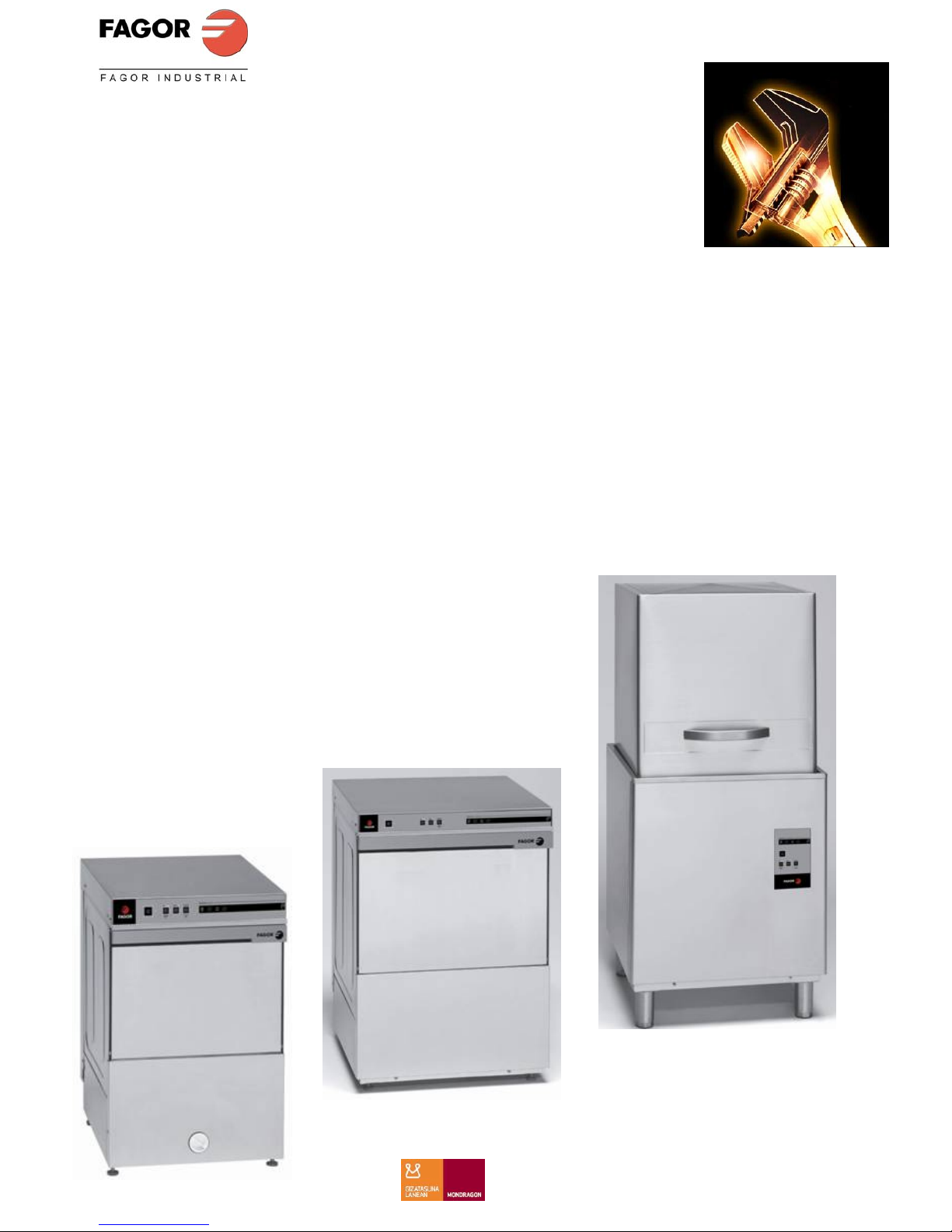
TECHNICAL MANUAL
DISH WASHER
“ADVANCE”
CSI INSTALACIONES
Page 2

Page 2 of 22
10/11/2009
PLATFORM
The platform used for controlling the low range, ADVANCE dishwasher (front loading, top loading
and glasswasher) is shown below.
ADVANCE
Serigraphy
Main
control
card
Temperature
Card
Card
Assembly
CSI INSTALACIONES
Page 3

Page 3 of 22
10/11/2009
As can be seen from the picture, the platform has 2 cards, the main controller card and the auxiliary
temperature card, in addition to a membrane keyboard with 4 buttons and 5 LEDs permitting
interaction with the appliance.
TEMPERATURE CARD
The temperature card is powered through the control card but does not have any communication
with this card. This card only displays the tank and boiler temperatures, making use of 2 external
thermostats linked to the card.
MAIN CONTROL CARD
The control card has 4 inputs and 5 outputs, in addition to 4 dip-switches for configuring the
appliance:
Inputs:
• TT / PC: Thermostat indicating whether the established tank temperature has been reached.
On the other hand, for a Clinic appliance, that is an appliance with break tank, this input
indicates the status of the boiler pressure switch
• PT Input displaying the status of the tank pressure switch
• TC: Displays the status of the boiler thermostat (CAUTION! The status of this input
signifies the opposite to that of the TT input)
• IP: Input indicating the status of the door
Outputs:
• V: Water inlet solenoid valve
• MBL: Wash pump
• Vreg: Regeneration solenoid valve. In a Clinic appliance, this valve is used to fill the boiler
• BD: Drainage pump
• RG: Main relay which disables the remaining outputs if not active
CSI INSTALACIONES
Page 4

Page 4 of 22
10/11/2009
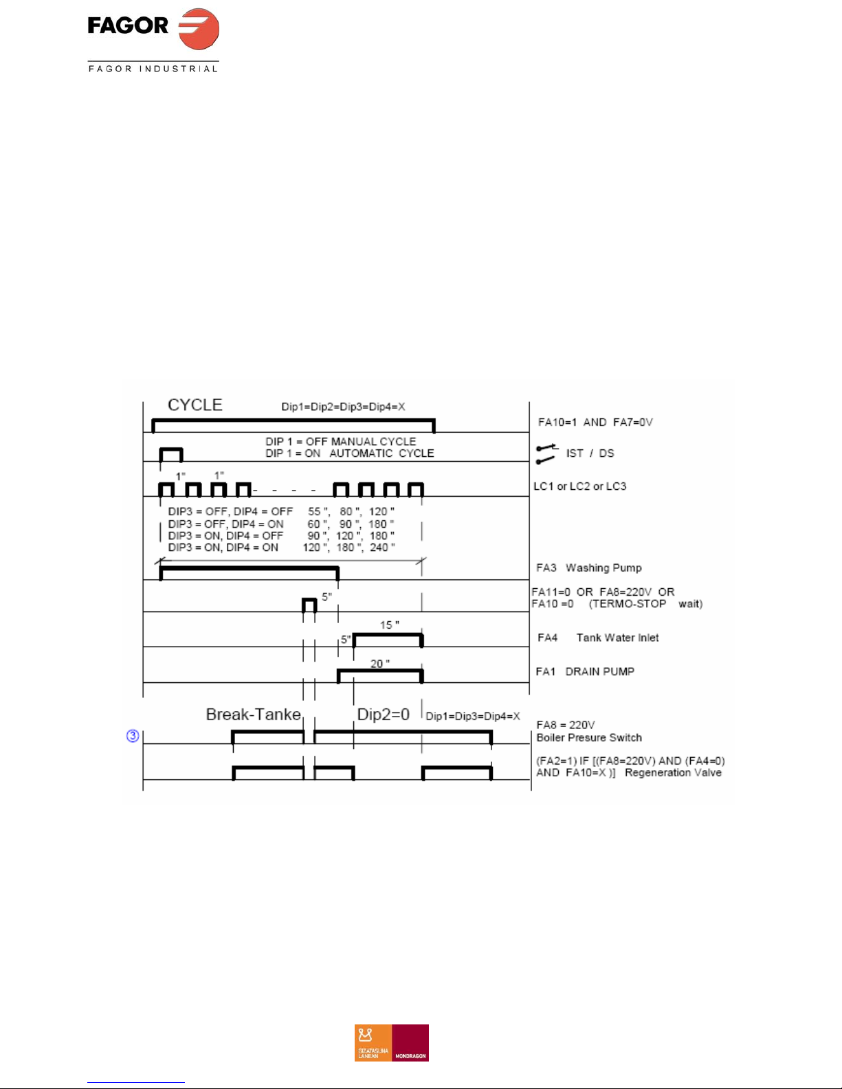
The configuration of the DIP-Switches is as follows:
o DIP1: Door
o If DIP1=0
Glass washer and front loading. To begin a new wash cycle, select the
required programme, the appliance is on stand-by meanwhile
o If DIP1=1
Top loading: To start a new wash cycle, just open and close the door, and
the last used programme is run
o DIP2: Regeneration
o If DIP2=0
The appliance does not have descaler
o If DIP2=1
The appliance has descaler Therefore, if B2 is pressed for 3 seconds, the
descaler cycle is activated
o DIP3: Time
o If DIP1=0& DIP3=0
P1=90 / P2=120 / P3=180
o If DIP1=0& DIP3=1
P1=60 / P2=90 / P3=180
o If DIP1=1& DIP3=0
P1=90 / P2=120 / P3=180
o If DIP1=1& DIP3=1
P1=55 / P2=80 / P3=120-∞
o DIP4: Clinic Line with break tank
o If DIP4=0: This is not a clinic line appliance
o If DIP4=1
Vreg (The output Vreg is used as a boiler filler valve)
For the thermostop, in addition to TC, TT should also be considered (PC in
this case). Do not end wash until TC=0 and TT=0
CSI INSTALACIONES
Page 5
Page 5 of 22
10/11/2009
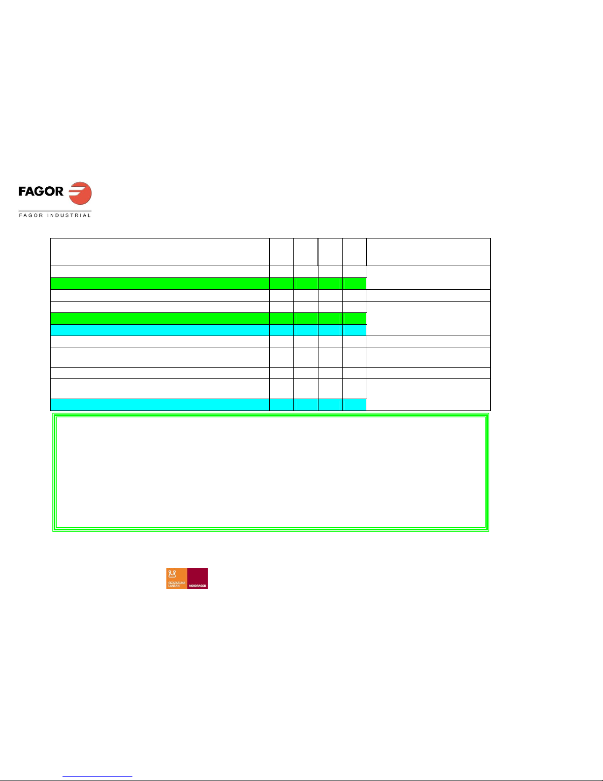
FAGOR ELECTRONIC ADVANCE MODEL DIP1 DIP2 DIP3 DIP4 CYCLE TIMES (s)
OTHER GLASSWASHER MODELS OFF OFF OFF OFF
AD-15 D , AD-21 D OFF ON OFF OFF
P1=90 / P2= 120 / P3=180
OTHER GLASSWASHER MODELS A.F. OFF OFF ON OFF
AD-48 D, AD-64 D OFF ON ON OFF
AD-48 HY, AD-64 HY OFF OFF ON ON
P1=60 / P2= 90 / P3=180
OTHER GLASSWASHER MODELS TOP LOADING
AD-90…. ON OFF OFF OFF
P1=75 / P2= 120 / P3=180
OTHER GLASSWASHER MODELS TOP LOADING
AD-120... ON OFF ON OFF
AD-120 HY ON OFF ON ON
P1=55 / P2= 80 / P3=120 - ∞
DIP1 = ON, when the door is closed or the cover lowered, the dishwasher st arts.
DIP1= OFF, when the door is closed or the cover lowered, the dishwasher conti nues washi ng ONLY IF THE CYCLES HAS NOT
FINISHED.
DIP2 = ON, For models fitted with WATER SOFTENER, version “D”.
DIP2 = OFF, For models with DRAINAGE PUMP, versions “B”.
DIP1 + DIP3 , with the different posible combinations, we programme the cycle times
DIP4 = ON, For models “HY”
DIP4 = OFF, For models wich do NOT have Break Tank “HY”
CSI INSTALACIONES
Page 6
Page 6 of 22
10/11/2009
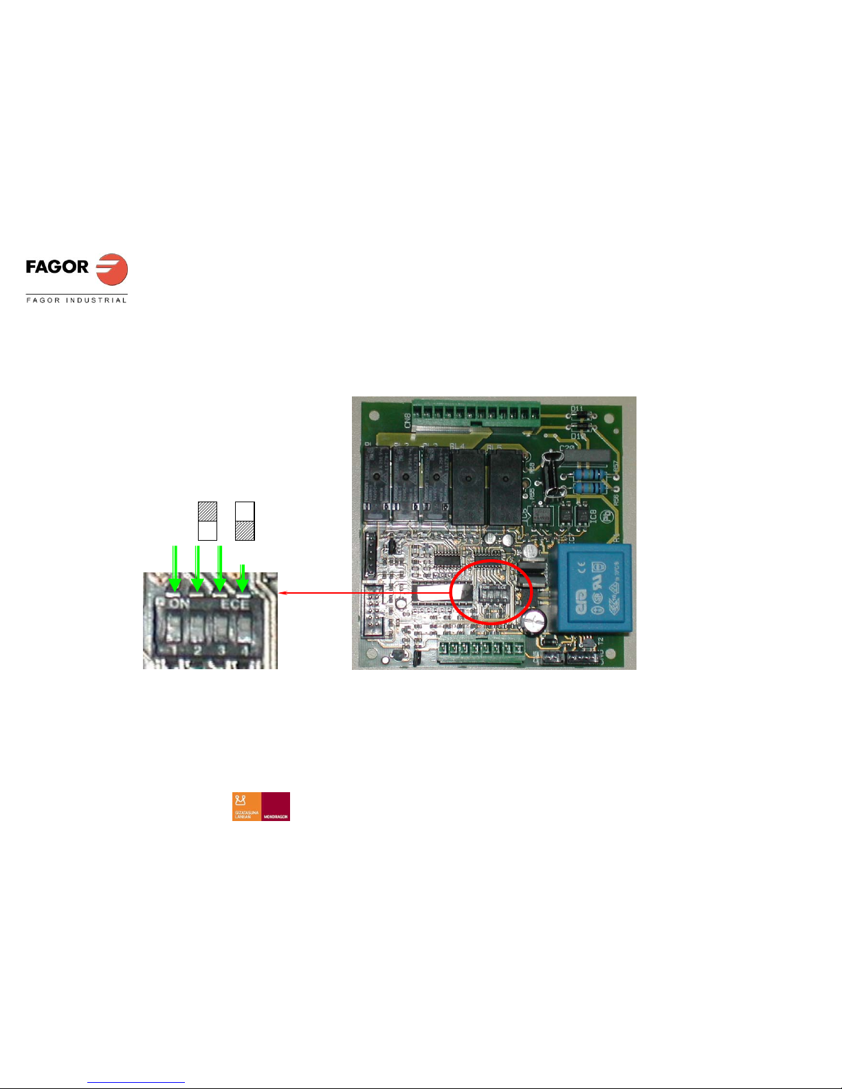
DIPS
ON
OFF
CSI INSTALACIONES
Page 7

Page 7 of 22
10/11/2009
INTERFACE
One of the possible serigraphic combinations (membrane keyboard) is shown below. This has been
designed to interact with the 5 RELAY card.
These are the components of the above combination:
B1 (ON/OFF button)
o Button for switching appliance on/off. The button should be pressed for 2 seconds
L1 (ON/OFF LED)
o LED indicating whether the appliance is ON or OFF. If the appliance is running, the LED is lit,
otherwise it is off
Note: Depending on the model, this button may have the auxiliary function of descaler or drainage
pump
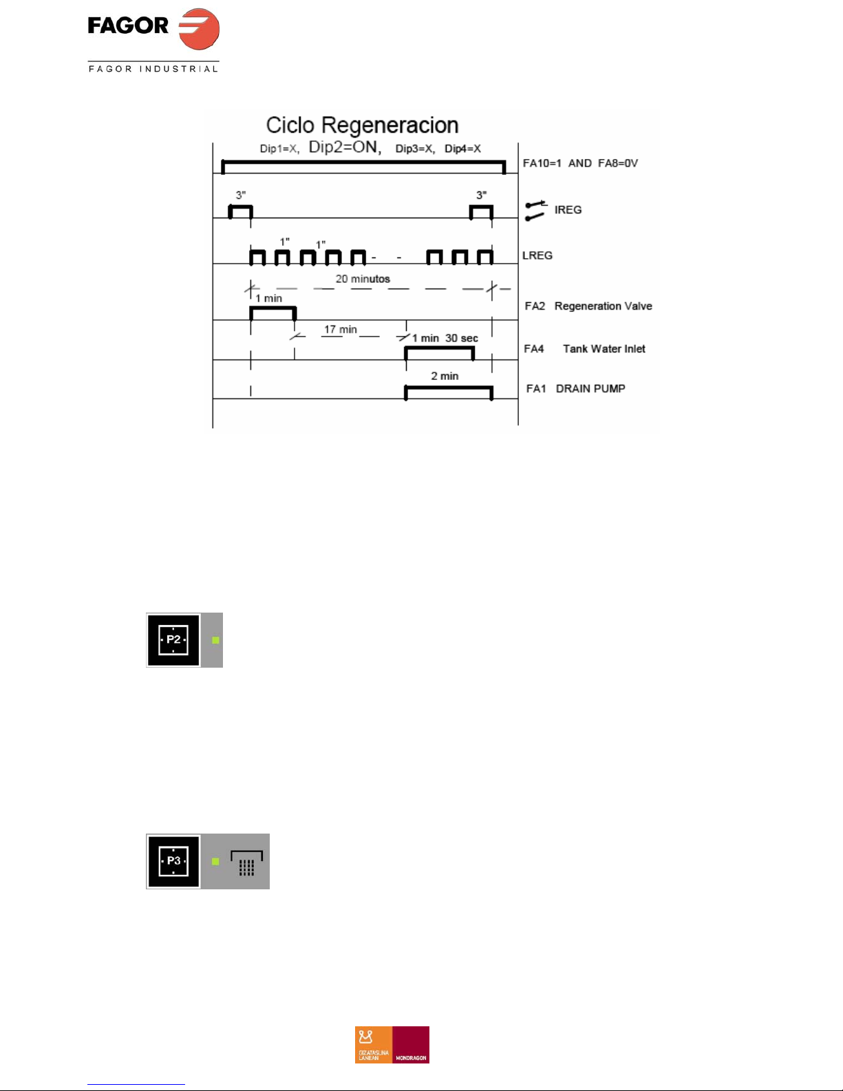
B2 (Button P1)
o If this button is pressed once, the dishwasher will start to wash with programme 1, provided
the door is closed
o If the button is pressed for 3 seconds, this activates the function corresponding to the right
icon (Descaler or drainage pump, depending upon the DIP2 configuration)
o If DIP2=0: Drainage pump If the door is open (relief valve removed) the drainage
pump is activated for 2 minutes (As with the EDESA software)
o If DIP2=1: Descaler: The regeneration cycle is run, as shown in the above graph.
CSI INSTALACIONES
Page 8
Page 8 of 22
10/11/2009
L2 (LED P1)
o If the appliance is washing, this LED remains lit. It is also lit if the appliance is in PAUSE
mode, i.e., if the door has been opened
o If the descaler or drainage pump function is activated, the LED flashes
o If the appliance is not washing, this LED is off.
B3 (Button P2)
o If this button is pressed once, the dishwasher starts to wash with programme 2
L3 (LED P2)
o If the appliance is washing, this LED remains lit. It is also lit if the appliance is in PAUSE
mode, i.e., if the door has been opened
o If the appliance is not washing, this LED is off.
Note: Depending on the model, this button may have the auxiliary function of cold rinse or indefinite
cycle
CSI INSTALACIONES
Page 9

Page 9 of 22
10/11/2009
B4 (Button P3)
o If this button is pressed once, the dishwasher starts to wash with programme 3
o If the button is pressed for 3 seconds, this activates the function corresponding to the right
icon (Cold rinse or indefinite cycle, depending upon the DIP1 configuration)
o If DIP1=0 and DIP2=0: Cold rinse: The cold rinse solenoid valve remains on while
the button is pressed
o If DIP1=1& DIP3=1: Indefinite cycle: The dishwasher remains on indefinitely. If the
indefinite cycle is active, pressing the button again for 3 seconds will deactivate it
L4 (LED P3)
o If the appliance is washing, this LED remains lit. It is also lit if the appliance is in PAUSE
mode, i.e., if the door has been opened
o If the cold rinse function or the indefinite cycle is on, the LED flashes
o If the appliance is not washing, this LED is off.
Note: Depending on the model, this LED may or may not exist
L5 (LED Machine Ready)
o If the tank thermostat has reached the programmed temperature, this LED lights up
o If the tank thermostat has not reached the programmed temperature, this LED is OFF
The models without a machine ready LED, there are 2 displays.
Rinse temperature
Washing temperature
CSI INSTALACIONES
Page 10
Page 10 of 22
10/11/2009
GENERAL OPERATION
To switch on the appliance, press button B1 (Button ON/OFF), when the required programme button
is pressed the dishwasher starts, provided that the tank has been filled with water.
When the programme is selected the machine starts and runs for the time established for this cycle,
starting the countdown to zero when the machine stops. If the door is opened at any moment, the
appliance and the countdown will PAUSE, and start operating normally again when the door is
stopped.
When a programmed cycle ends, the dishwasher remains in stand-by until:
• A new programme is selected in the case of a FRONT LOADING GLASSWASHER
• A new programme is selected or the door is opened or closed in the case of a TOP
LOADING DISHWASHER. In the latter case, the last used programme is run.
CSI INSTALACIONES
Page 11

Page 11 of 22
10/11/2009
DIAGNOSTICS
The software should also diagnose any faults, informing of the action via impulse trains of the
ON/OFF LED. The trains are formed of X 0.5” impulses (ON) and a wait of 2”, as shown in the
diagram below.
Example of a 2-impulse train
The diagnostics defined are listed below:
1. If DIP1=1 (Not top loading), Ip=0 (door open) and programme running (start or in middle):
This is indicated by a one-impulse train
2. If PT=1 (Tank not full) for 6 minutes, and BD=0 (Not draining): This is indicated by a two-
impulse train
3. If PT=0 (Tank full) for 1 minute, and BD=1 (draining): This is indicated by a three-impulse
train
4. If PT=0 (Tank full) and TC=1 (boiler temperature not reached) for 5 minutes: This is indicated
by a four-impulse train
5. If TT=0 (tank temperature not reached) for 60 minutes and MBL=V=0 (Wash pump motor
stopped and without entering water): This is indicated by a five-impulse train
CSI INSTALACIONES
Page 12

Page 12 of 22
10/11/2009
CSI INSTALACIONES
Page 13
Page 13 of 22
10/11/2009
CSI INSTALACIONES
Page 14

Page 14 of 22
10/11/2009
CSI INSTALACIONES
Page 15

Page 15 of 22
10/11/2009
CSI INSTALACIONES
Page 16

Page 16 of 22
10/11/2009
CSI INSTALACIONES
Page 17

Page 17 of 22
10/11/2009
Wate
r
Power(kW
)
Duration Capacit Consumptio Net
MODE
inlet Resisto
rMax
Min. of rinse weigh
pressure
Voltage
power
supply.
Dru Tub absorb
Basket
(mm)
cycle tub(l) water(l) (kg)
AD-15
2÷4 kg/cm
(28÷56psi)
AD15D
3.5÷5
Kg/cm
(42÷70psi)
2.4 2.66
350x35
0
11 2 36
AD-21
2÷4 Kg/cm
(28÷56psi
AD21D
3.5÷5
Kg/cm
(42÷70psi)
3.06
2 MAX.
(Controllable)
39
AD21B
AD21C
2÷4 Kg/cm
(28÷56psi)
220-240V - 1N
(50/60Hz)
2.8
2
3.14
400x40
0
2
(Fixed)
15 2.5
42
Wate
r
V
oltage Power(kW
)
Basket, Duratio Capacit Consumptio Net
MODEL
inlet
p
ower ResistorMa
x
square Min. of rinse weigh
pressure Dru Tub absorb
(mm) tub(l) water(l) (kg)
AD - 48
(200÷400 kPa)
(2÷4 Kg/cm
2)
(28÷56 psi)
AD-48D
(400÷500 kPa)
(4÷5 Kg/cm
2)
(56÷70 psi)
3.45
60
A
D-48B-BT
AD
-
48HY CLINIC
63
AD - 48B
(200÷400 kPa)
(2÷4 Kg/cm
2)
(28÷56 psi)
220-240-1N~
380-415-3N~
(50/60Hz.)
2.8
2.8
3.52
500x50
0
120’’
180’’
25
2.7
60
CSI INSTALACIONES
Page 18

Page 18 of 22
10/11/2009
Water Power(kW) Basket, Capacit Consumptio Net
MODEL
inlet Resistor Max square of rinse weigh
pressure
Drainage hose
Power supply
voltage
Dru Tub absorb (mm)
Cycle
duration
tub(l) water(l) (kg)
AD - 64
6.65 60
AD - 64B
AD - 64B-BT
AD – 64HY
CLINIC
AD – 64C
(200÷400 kPa)
(2÷4 Kg./cm)
(28÷56 psi)
6.72 66
AD – 64D
(400÷500 kPa)
(4÷5 Kg./cm)
(56÷70 psi)
65
AD - 72
(200÷400 kPa)
(2÷4 Kg./cm)
(28÷56 psi)
ø30xø25
380-415V-3N
220V-3
220-240V-1N
(50/60Hz)
6 2.8
6.65
500x50
0
90”
180”
25 2.7
69
Water Power(W) Basket,
Consumptio Net
MODEL
inlet Resistor Max square rinse
weigh
pressure
Drainage
hose
Voltage
supply
Drum Tub absorbe (mm) water(l) (kg)
AD – 90
AD – 90 B BT
6,000 11,100 108
108
AD – 100
AD – 100 B
AD – 100 C
AD – 100 B BT
9,000 14,700
116
AD – 120
AD – 120 B
AD – 120 C
200-400 kPa
(2÷4
Kg/cm)
(29-58psi)
ø30x ø25
380-415V-
3N
220-240V-
3N
220-240V-
1N
(50/60Hz.)
12,000
4,500
17,700
500x50
0
3
118
CSI INSTALACIONES
Page 19

Page 19 of 22
10/11/2009
NOTES
CSI INSTALACIONES
Page 20

Page 20 of 22
10/11/2009
NOTES
NOTES
CSI INSTALACIONES
Page 21

Page 21 of 22
10/11/2009
NOTES
CSI INSTALACIONES
Page 22

Page 22 of 22
10/11/2009
CSI INSTALACIONES
 Loading...