

Faber JELLING Installation Manual
JELLING
Installationguide
IRL U
K
40010705 - 0821
1 < < < <
UK IRL
General
1.1 1.2
1.3 1.4
1.5
> > > > 2
UK IRL
1.6
1.7 1.8

3 < < < <
UK IRL
Introduction
Note: these instructions should be read carefully and retained for future reference.
Please leave these instructions with the user.
Content
1 Safety and general information .................................................................. 4
2 Installation requirements ......................................................................... 5
2.1 Flue requirements............................................................................ 5
2.2 Flue restrictor ................................................................................ 5
2.3 Terminal position ............................................................................ 6
3 Instruction for Installation ........................................................................ 7
3.1 Gas connection ............................................................................... 7
3.2 Electric connection .......................................................................... 7
3.3 Preparing the appliance..................................................................... 7
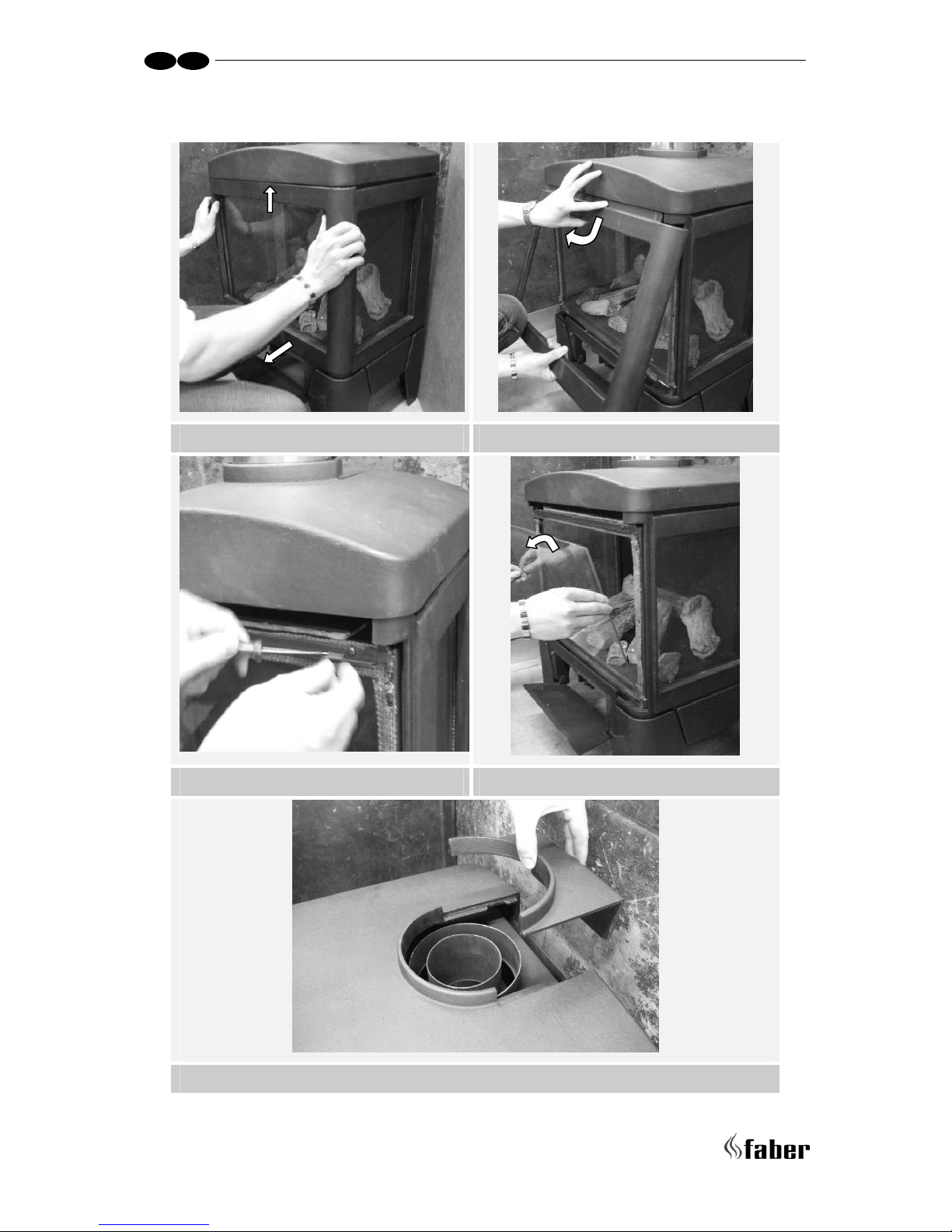
3.4 Removing of the glass ....................................................................... 7
3.5 Connection with use of concentric duct material ...................................... 8
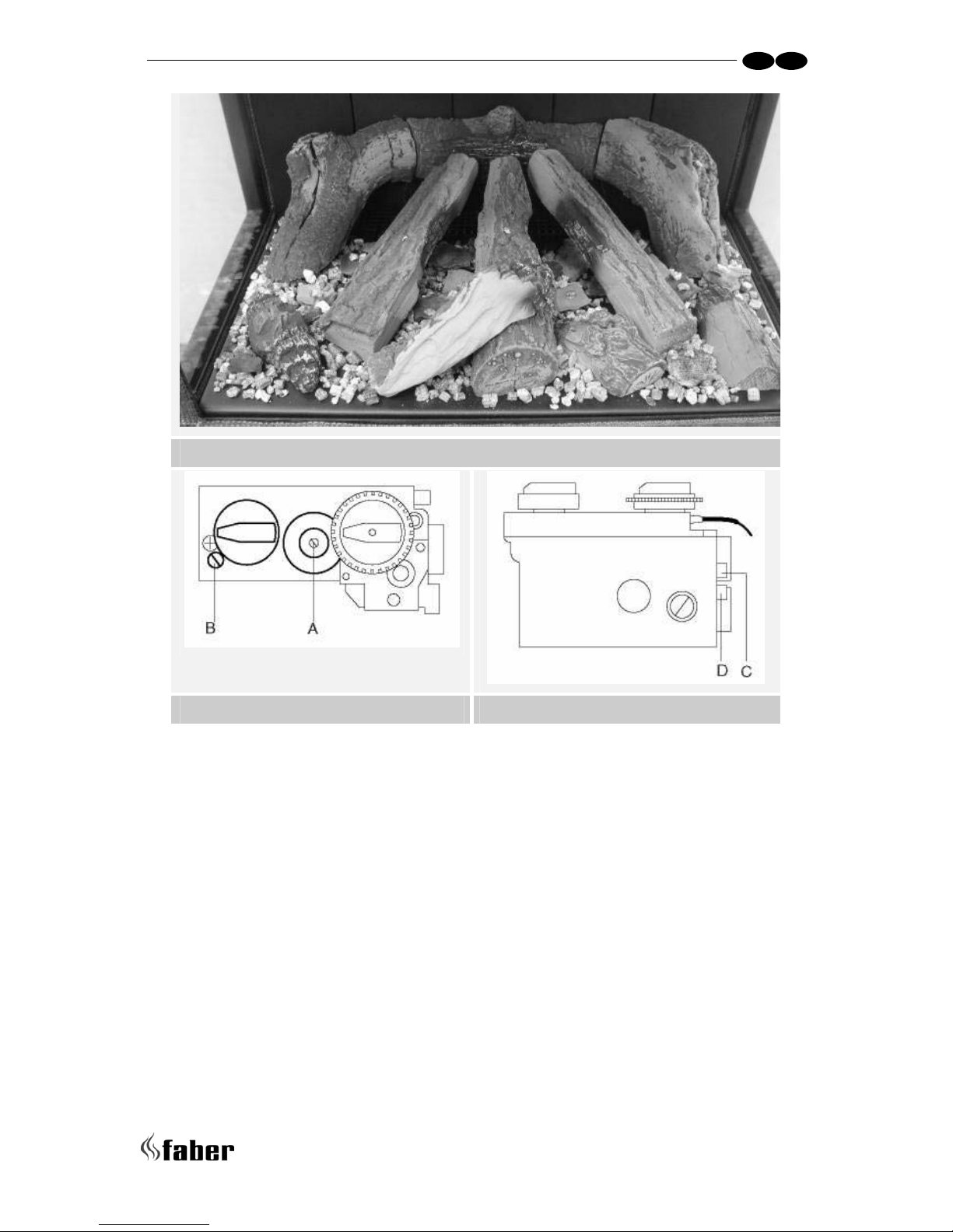
3.6 Placing the log set ........................................................................... 8
4 Commissioning (functional checks) .............................................................. 9
4.1 Pilot ignition check .......................................................................... 9
4.2 Check functional burner and pilot burner................................................ 9
5 Handing over (final check and customer briefing) ...........................................10
6 Service...............................................................................................10
6.1 Routine annual servicing...................................................................10
6.2 Cleaning the glass...........................................................................10
6.3 Cleaning the combustion chamber and burner.........................................11
6.4 Rebuild to other gas category (e.g. Propane/butane) ............................... 11
Appendix A: Example calculation..................................................................... 12
Appendix B: Flue restrictor............................................................................13
Appendix C : Technical specifications...............................................................14
Appendix D: Dimensions Jelling.......................................................................15

> > > > 4
UK IRL
1 Safety and general information
Before installation, ensure that the local distribution conditions (identification of the type
of gas and pressure) and the adjustment of the appliance are compatible.
This gas appliance is factory set and can not be adjusted.
This appliance does not contain any component manufactured from asbestos or any
asbestos related products.
Ventilation
This appliance is room-sealed and doesn't require purpose provided ventilation.
Never use the appliance if it has a broken glass.
General safety
It is the law in the UK that all gas appliances, are installed by a competent person in
accordance with the Gas Safety (Installation and Use) Regulations (as amended), the
relevant British Standards for Installation work, Building Regulations, Codes of Practice and
the manufacturers instructions.
Always use an additional guard if there are elderly, infirm or children in the same room of
the appliance.
The installation should also be carried out in accordance with the following where
relevant:
• BS5871 Part1
• BS5440 Parts 1 & 2
• BS1251
• Building Regulations Document J (as applicable)
• Building Regulations and Standards issued as relevant by the Department of the
Environment or the Scottish Development Department
• In the Republic of Ireland installation should be carried out in accordance with
IS813, ICP3, IS327, Building Regulations, Codes of Practice, the manufacturers
instructions and all other regulations in force
Failure to comply with the above could leave the installer liable to prosecution and
invalidate the appliance warranty.

5 < < < <
UK IRL
2 Installation requirements
Note: Since the appliance is a source of heat, circulation of air occurs. Therefore it is of
importance that you do not use the appliance shortly after a renovation of the home.
Because of the natural circulation of air, moist and volatile components from paint,
building materials, carpet etc. will be attracted. These components can settle onto cold
surfaces in the form of soot.
As on all heat producing appliances, soft furnishings such as blown vinyl wallpaper placed
too near to the appliance may become scorched or discoloured. This should be born in
mind when installing the appliance.
2.1 Flue requirements
• The appliance is of the type C31. The appliance will need to be supplied with the
approved flue pipes and terminal, it is not possible to supply your own
• a horizontal extension with elbows is allowed for a maximum of 6 meters
(depending on the situation)
• Vertical flue routing between 0.5 – 12 meter (depending on situation)
Determine on the base of the example calculations in Appendix A and on the base of the
table in Appendix B if the desired situation is possible. To establish this you will need to
calculate:
• The effective height (this is the real difference in height between the upper side of
the appliance and the terminal)
• The total horizontal extension. This is the total horizontal flue length where:
1. each elbow, which is in the horizontal area, counts for 2 meters
2. each 90-degree bend, which is in the horizontal area, counts for 2 meter
3. each 45-degree bend, which is in the horizontal area, counts for 1 meter
4. elbows and bends at the transition of horizontal to vertically are not to be
counted
5. the wall mounted terminal counts for 1 meter
2.2 Flue restrictor
If applicable, in the table of appendix B is also stated the size of a flue restrictor. This
restrictor needs to be fitted in the combustion chamber when placing the appliance.
Normally the smallest flue restrictor is fitted at production.
 Loading...