

Page 1
Instructions Manual
Manuel d’Instructions
Bedienungsanleitung
Manual de instrucciones
Εγχειρίδιο οδηγιών
Руководство по эксплуатации
Kullanim Kilavuzu
Naudojimosi instrukcija
Instrukcijas Grāmata
Kasutusjuhend
Page 2

INDEX
RECOMMENDATIONS AND SUGGESTIONS ..................................................................................................................... 4
CHARACTERISTICS ............................................................................................................................................................. 7
INSTALLATION...................................................................................................................................................................... 8
USE ...................................................................................................................................................................................... 11
MAINTENANCE................................................................................................................................................................... 12
EN
SOMMAIRE
CONSEILS ET SUGGESTIONS.......................................................................................................................................... 15
CARACTERISTIQUES......................................................................................................................................................... 18
INSTALLATION.................................................................................................................................................................... 19
UTILISATION .......................................................................................................................................................................22
ENTRETIEN......................................................................................................................................................................... 23
FR
INHALTSVERZEICHNIS
EMPFEHLUNGEN UND HINWEISE ................................................................................................................................... 26
CHARAKTERISTIKEN......................................................................................................................................................... 29
MONTAGE ...........................................................................................................................................................................30
BEDIENUNG........................................................................................................................................................................ 33
WARTUNG........................................................................................................................................................................... 34
DE
ÍNDICE
CONSEJOS Y SUGERENCIAS........................................................................................................................................... 37
CARACTERÍSTICAS ........................................................................................................................................................... 40
INSTALACIÓN ..................................................................................................................................................................... 41
USO...................................................................................................................................................................................... 44
MANTENIMIENTO............................................................................................................................................................... 45
ES
ΠΕΡΙΕΧΟΜΕΝΑ
ΣΥΜΒΟΥΛΕΣ ΚΑΙ ΣΥΣΤΑΣΕΙΣ............................................................................................................................................ 48
ΧΑΡΑΚΤΗΡΙΣΤΙΚΑ............................................................................................................................................................... 51
ΕΓΚΑΤΑΣΤΑΣΗ.................................................................................................................................................................... 52
ΧΡΗΣΗ ................................................................................................................................................................................. 55
ΣΥΝΤΗΡΗΣΗ........................................................................................................................................................................ 56
GR
УКАЗАТЕЛЬ
СОВЕТЫ И РЕКОМЕНДАЦИИ .......................................................................................................................................... 59
ХАРАКТЕРИСТИКИ............................................................................................................................................................ 62
УСТАНОВКА........................................................................................................................................................................ 63
ЭКСПЛУАТАЦИЯ................................................................................................................................................................ 66
УХОД.................................................................................................................................................................................... 67
RU
2
2
Page 3

IÇERIKLER
TAVSIYELER VE ÖNERILER.............................................................................................................................................. 70
ÖZELLIKLER........................................................................................................................................................................ 73
MONTAJ............................................................................................................................................................................... 74
KULLANIM ........................................................................................................................................................................... 77
BAKIM .................................................................................................................................................................................. 78
TR
TURINYS
PATARIMAI IR NUORODOS............................................................................................................................................... 81
PRIETAISO APRAŠYMAS .................................................................................................................................................. 84
MONTAVIMAS..................................................................................................................................................................... 85
NAUDOJIMAS...................................................................................................................................................................... 88
VALYMAS IR PRIEŽIŪRA ................................................................................................................................................... 89
LT
INDEKSS
IETEIKUMI UN PRIEKŠLIKUMI........................................................................................................................................... 92
TEHNISKIE DATI................................................................................................................................................................. 95
UZSTĀDĪŠANA.................................................................................................................................................................... 96
IZMANTOŠANA ................................................................................................................................................................... 99
APKOPE............................................................................................................................................................................. 100
LV
INDEKS
SOOVITUSED JA ETTEPANEKUD................................................................................................................................... 103
OMADUSED....................................................................................................................................................................... 106
PAIGALDAMINE ................................................................................................................................................................ 107
KASUTAMINE....................................................................................................................................................................110
HOOLDUS.......................................................................................................................................................................... 111
EE
3
3
Page 4
RECOMMENDATIONS AND SUGGESTIONS
The Instructions for Use apply to several versions of this appliance.
Accordingly, you may find descriptions of individual features that do not
apply to your specific appliance.
INSTALLATION
• The manufacturer will not be held liable for any damages resulting from
incorrect or improper installation.
• The minimum safety distance between the cooker top
and the extractor hood is 650 mm (some models can
be installed at a lower height, please refer to the
paragraphs on working dimensions and installation).
• Check that the mains voltage corresponds to that
indicated on the rating plate fixed to the inside of the
hood.
• For Class I appliances, check that the domestic
power supply guarantees adequate earthing.
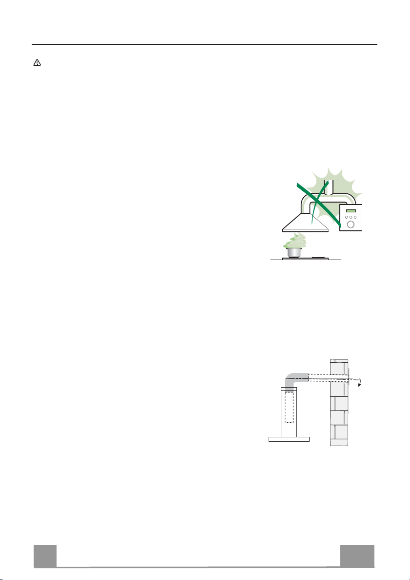
Connect the extractor to the exhaust flue through a pipe of minimum
diameter 120 mm. The route of the flue must be as short as possible.
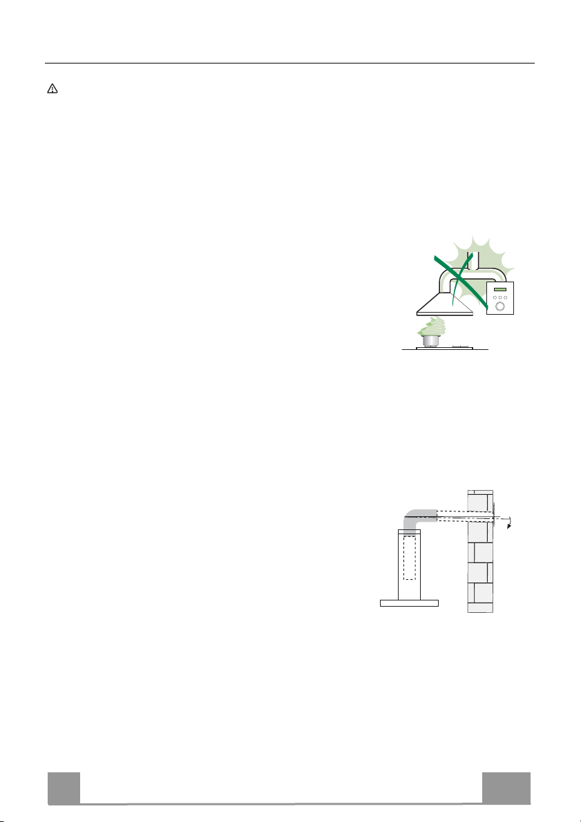
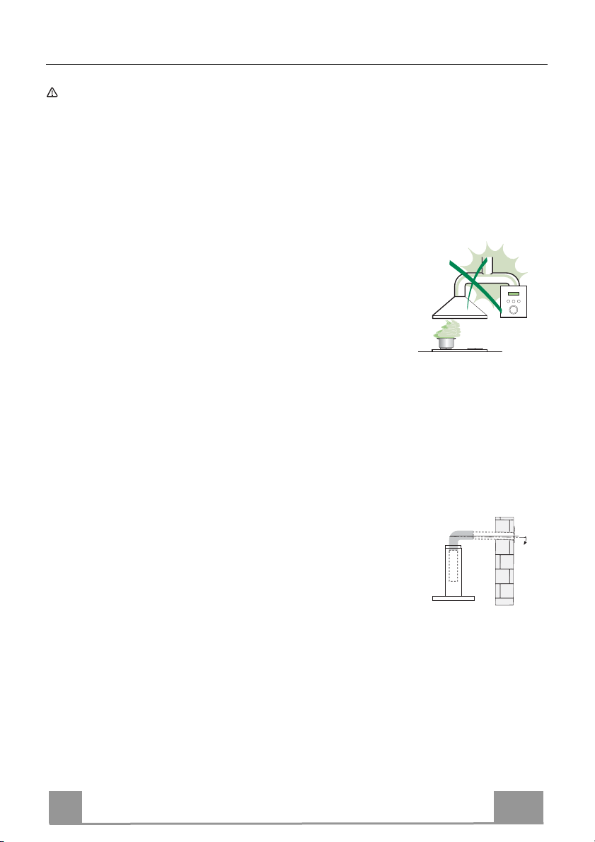
• Do not connect the extractor hood to exhaust ducts carrying combustion
fumes (boilers, fireplaces, etc.).
• If the extractor is used in conjunction with nonelectrical appliances (e.g. gas burning
appliances), a sufficient degree of aeration must
be guaranteed in the room in order to prevent the
backflow of exhaust gas. The kitchen must have
an opening communicating directly with the open
air in order to guarantee the entry of clean air.
When the cooker hood is used in conjunction with
appliances supplied with energy other than electric, the negative pressure in
the room must not exceed 0,04 mbar to prevent fumes being drawn back
into the room by the cooker hood.
• In the event of damage to the power cable, it must be replaced by the
manufacturer or by the technical service department, in order to prevent any
risks.
2°
EN
4
4
Page 5
• If the instructions for installation for the gas hob specify a greater distance
specified above, this has to be taken into account. Regulations concerning
the discharge of air have to be fulfilled.
• Use only screws and small parts in support of the hood.
Warning: Failure to install the screws or fixing device in accordance with
these instructions may result in electrical hazards.
• Connect the hood to the mains through a two-pole switch having a contact
gap of at least 3 mm.
USE
• The extractor hood has been designed exclusively for domestic use to
eliminate kitchen smells.
• Never use the hood for purposes other than for which it has been designed.
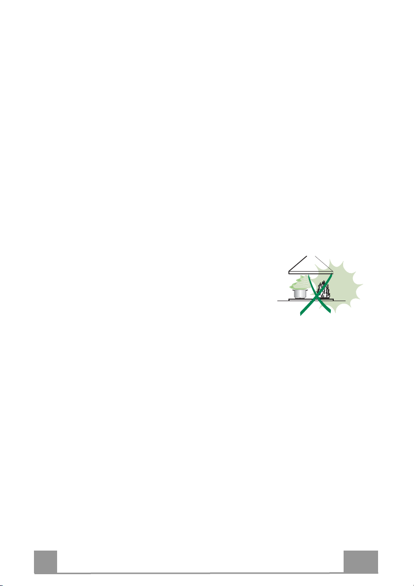
• Never leave high naked flames under the hood when it is in operation.
• Adjust the flame intensity to direct it onto the bottom of the pan only, making
sure that it does not engulf the sides.
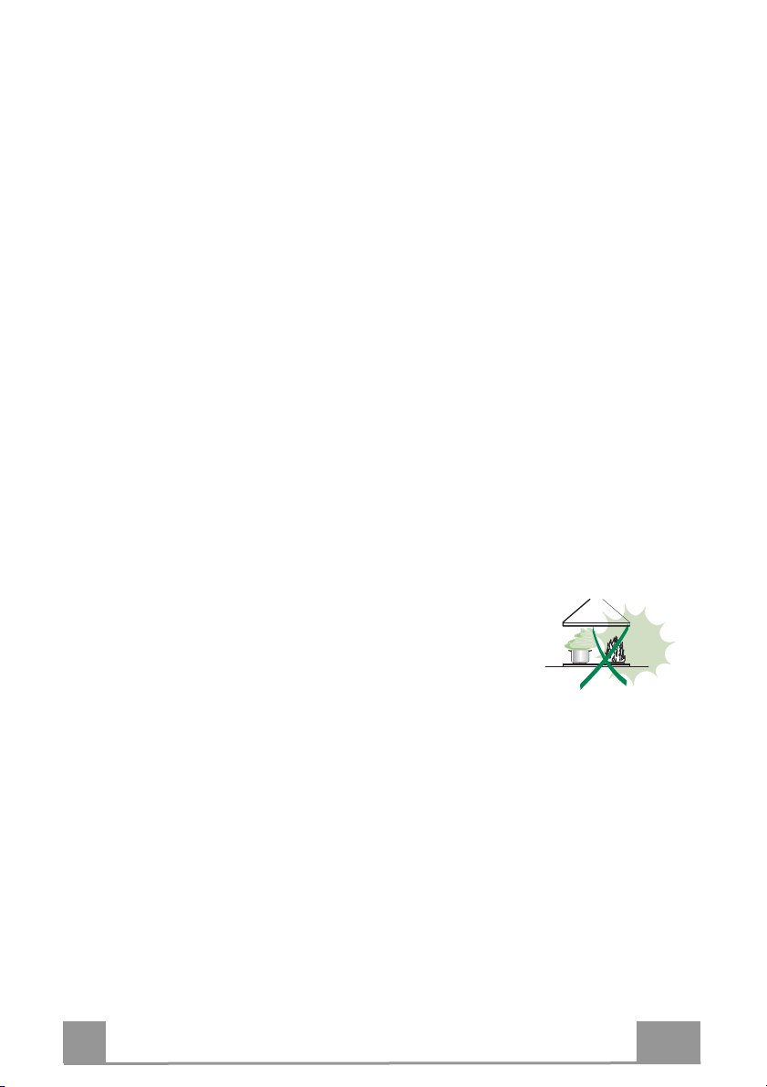
• Deep fat fryers must be continuously monitored
during use: overheated oil can burst into flames.
• Do not flambè under the range hood; risk of fire.
• This appliance can be used by children aged from
8 years and above and persons with reduced
physical, sensory or mental capabilities or lack of
experience and knowledge if they have been given supervision or instruction
concerning use of the appliance in a safe way and understand the hazards
involved. Children shall not play with the appliance. Cleaning and user
maintenance shall not be made by children without supervision.
EN
5
5
Page 6
• “CAUTION: Accessible parts may become hot when used with cooking
appliances.”
MAINTENANCE
• Switch off or unplug the appliance from the mains supply before carrying out
any maintenance work.
• Clean and/or replace the Filters after the specified time period (Fire hazard).
• The Grease filters must be cleaned every 2 months of operation, or more
frequently for particularly heavy usage, and can be washed in a dishwasher.
• The Activated charcoal filter is not washable and cannot be regenerated,
and must be replaced approximately every 4 months of operation, or more
frequently for particularly heavy usage.
• "Failure to carry out cleaning as indicated will result in a fire hazard".
• Clean the hood using a damp cloth and a neutral liquid detergent.
The symbol on the product or on its packaging indicates that this product
may not be treated as household waste. Instead it shall be handed over to the
applicable collection point for the recycling of electrical and electronic
equipment. By ensuring this product is disposed of correctly, you will help
prevent potential negative consequences for the environment and human
health, which could otherwise be caused by inappropriate waste handling of
this product. For more detailed information about recycling of this product,
please contact your local city office, your household waste disposal service or
the shop where you purchased the product.
EN
6
6
Page 7

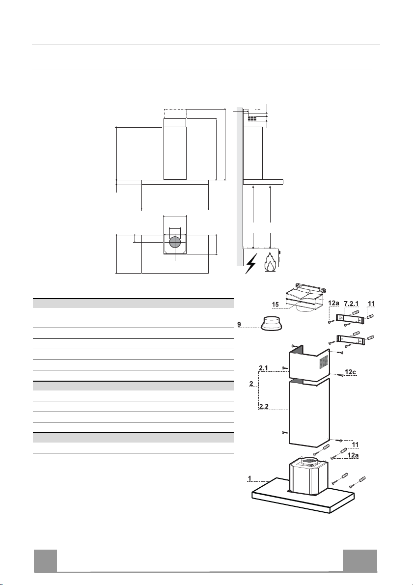
CHARACTERISTICS
Dimensions
1000
545
598-698-798-898-1198
300
150
108
470 45
730
260
Components
Ref. Q.ty Product Components
1 1 Hood Body, complete with: Controls, Light, Blower,
Filters
2 1 Telescopic Chimney comprising:
2.1 1 Upper Section
2.2 1 Lower Section
9 1 Reducer Flange ø 150-120 mm
15 1 Air Outlet Connection
Ref. Q.ty Installation Components
7.2.1 2 Upper Chimney Section Fixing Brackets
11 6 Wall Plugs
12a 6 Screws 4,2 x 44,4
12c 6 Screws 2,9 x 9,5
Q.ty Documentation
1 Instruction Manual
Min.
650mm
42
81
Min.
650mm
12b
64
EN
7
7
Page 8

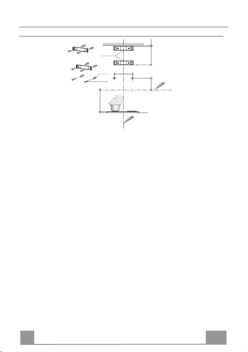
INSTALLATION
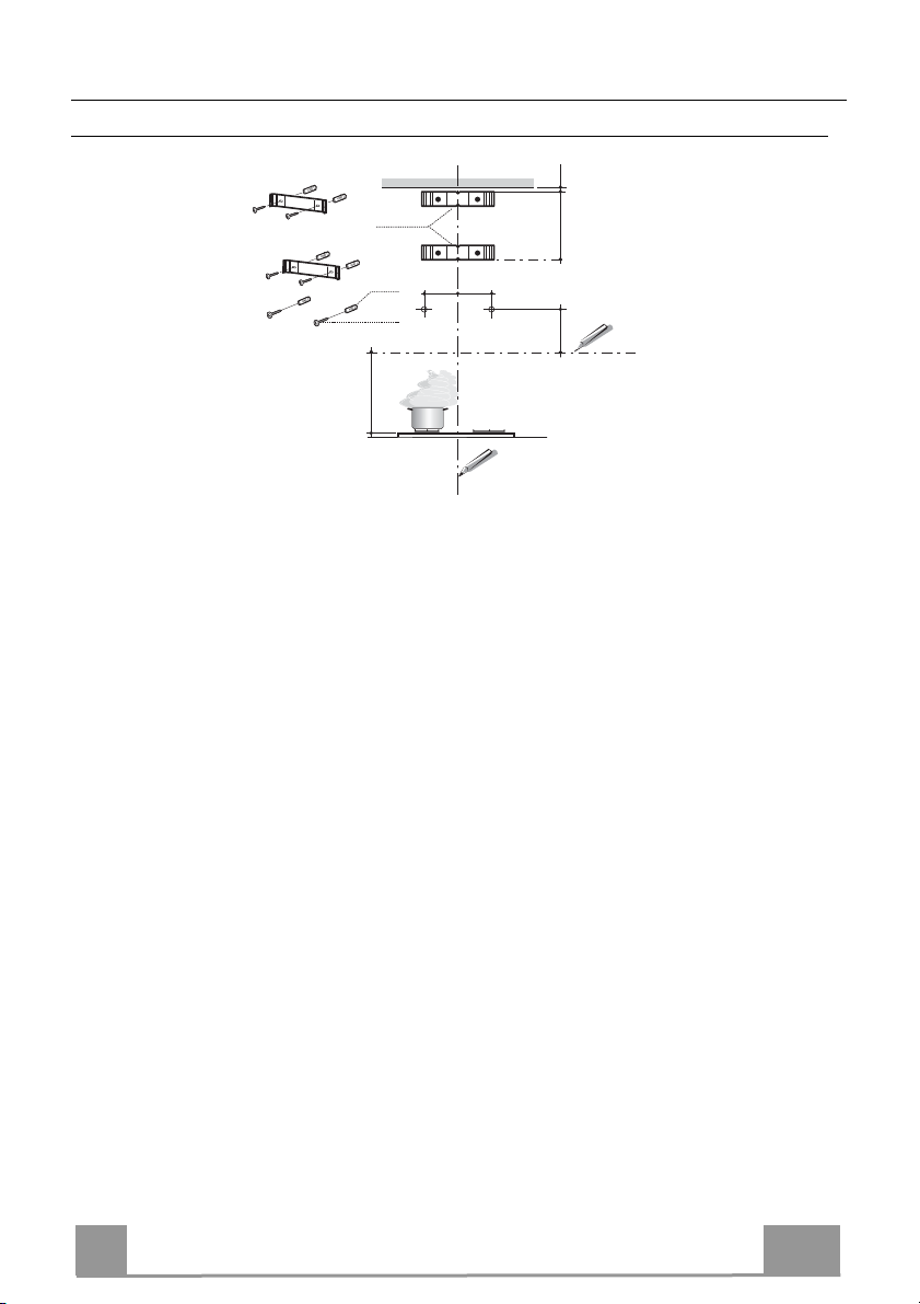
Wall drilling and bracket fixing
7.2.1
1÷2
X
11
12a
116
116
305
650 min.
Wall marking:
• Draw a vertical line on the supporting wall up to the ceiling, or as high as practical, at the
centre of the area in which the hood will be installed.
• Draw a horizontal line at 650 mm above the hob. Place bracket 7.2.1 on the wall as shown
about 1-2 mm from the ceiling or upper limit aligning the centre (notch) with the vertical
reference line.
• Mark the wall at the centres of the holes in the bracket.
• Place bracket 7.2.1 on the wall as shown at X mm below the first bracket (X = height of the
upper chimney section supplied), aligning the centre (notch) with the vertical line.
• Mark the wall at the centres of the holes in the bracket.
• Mark a reference point as indicated at 116 mm from the vertical reference line and 305 mm
above the horizontal reference line.
• Repeat this operation on the other side.
• Drill ø 8 mm holes at all the centre points marked.
• Insert the wall plugs 11 in the holes.
• Fix the brackets using the 12a (4,2 x 44,4) screws supplied.
• Insert the two screws 12a (4,2 x 44,4) supplied in the hood body fixing holes, leaving a gap
of 5-6 mm between the wall and the head of the screw.
EN
8
8
Page 9

Mounting the hood body
12a
Vr
9
ø 120ø 150
• Before attaching the hood body, tighten the two screws Vr located on the hood body mounting points.
• Hook the hood body onto the screws 12a.
• Fully tighten the support screws 12a.
• Adjust the screws Vr to level the hood body.
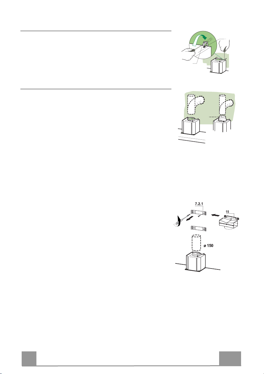
Connections
DUCTED VERSION AIR EXHAUST SYSTEM
When installing the ducted version, connect the hood to the
chimney using either a flexible or rigid pipe ø 150 or 120 mm,
the choice of which is left to the installer.
• To install a ø 120 mm air exhaust connection, insert the reducer flange 9 on the hood body outlet.
• Fix the pipe in position using sufficient pipe clamps (not supplied).
• Remove possible charcoal filters.
AIR OUTLET – RECIRCULATION VERSION
• Unfasten the 2 screws fixing the upper bracket 7.2.1.
• Fasten the air outlet connector 15 in its place, using the 2
screws removed as above.
• Join the Connector 15 to the Hood canopy outlet using a rigid
or flexible pipe ø150 mm, selection of which is at the
discretion of the installation technician.
• Make sure that the Activated charcoal odour filter has been
fitted.
EN
9
9
Page 10
ELECTRICAL CONNECTION
• Connect the hood to the mains through a two-pole switch having a contact gap of at least 3 mm.
• Remove the grease filters (see paragraph Maintenance) being
sure that the connector of the feeding cable is correctly inserted
in the socket placed on the side of the fan.
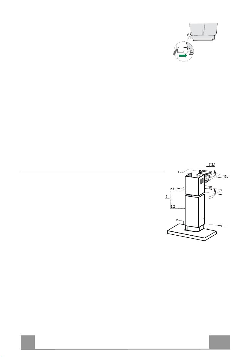
Flue assembly
Upper exhaust flue
• Slightly widen the two sides of the upper flue and hook them
behind the brackets 7.2.1, making sure that they are well
seated.
• Secure the sides to the brackets by using the 4 screws 12c (2,9
x 9,5) supplied.
• Make sure that the outlet of the extensions pieces is aligned
with the chimney outlets.
Lower exhaust flue
• Slightly widen the two sides of the flue and hook them between the upper flue and the wall, making sure that they are
well seated.
• Fix the lower part laterally to the hood body by using the 2
screws 12c (2,9 x 9,5) supplied.
12b
EN
10
1
Page 11

USE
L
T1 T2 T3 T4
L
T1 T4
Button Led Function
L
-
T1
Fixed Turns the motor on/off at speed one.
T2
Fixed Turns the Motor on at speed two.
T3
Fixed Turns the Motor on at speed three.
T4
Fixed Turns the Motor on at INTENSIVE Speed.
S1
Fixed Signals the Metal Grease Filter saturation alarm, indicating that it is necessary to
Flashing When this is activated, it signals the Activated Charcoal Filter saturation alarm,
Turns the lights on/off at maximum strength.
Press and hold the button for approximately 3 seconds, with all the loads turned
off (Motor and Lights), to turn the Activated Charcoal Filter alarm on. The
relevant LED flashes twice to confirm.
To turn the alarm off, press the button again and hold for at least 3 seconds. The
relevant LED flashes once.
Press and hold the button for approximately 3 seconds, with all the loads turned
off (Motor and Lights), to perform a reset of Filter saturation alarm. The LED S1
flashes three times.
This speed is timed to run for 6 minutes. At the end of this time, the system
returns automatically to the speed that was set before. If it is activated with the
motor turned off, the hood will switch to OFF at the end of the time.
Press and hold for 3 seconds to enable the remote control, indicated by the LED
flashing twice.
Press and hold for 3 seconds to disable the remote control, indicated by the LED
flashing just once.
wash the filters. The alarm is triggered after the Hood has been in operation for
100 working hours. (Reset see the parag. Maintenance)
indicating that the filter must be changed; the Metal Grease Filters must also be
washed. The Activated Charcoal Filter saturation alarm comes
into operation after the Hood has been working for 200 hours. (Activation and
Reset see the parag. Maintenance)
S1
T3S1T2
L
T1
T2
T3
T4
S1
Control panel
EN
11
1
Page 12

MAINTENANCE
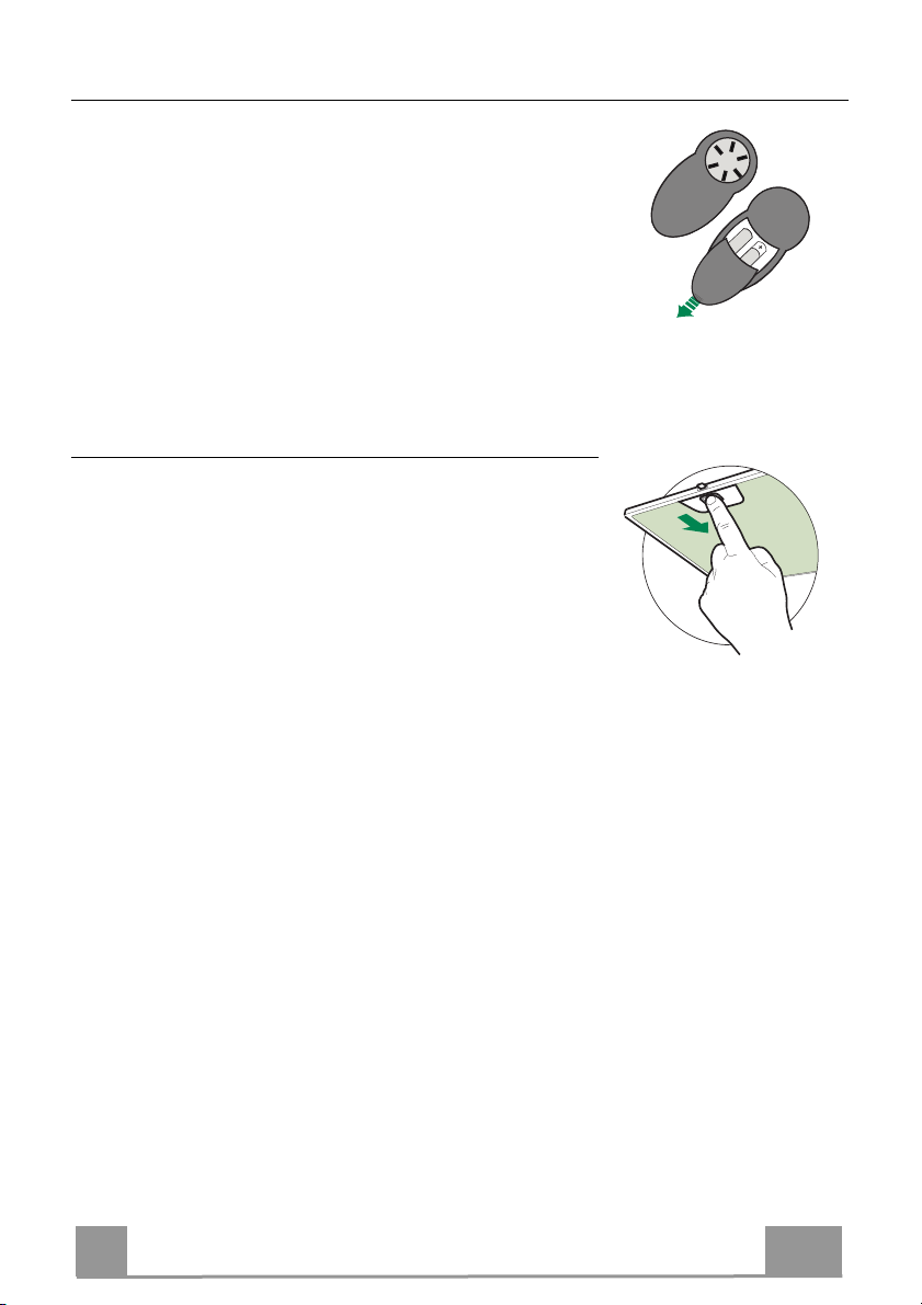
REMOTE CONTROL (OPTIONAL)
The appliance can be controlled using a remote control powered
by a 1.5 V carbon-zinc alkaline batteries of the standard LR03AAA type (not included).
• Do not place the remote control near to heat sources.
• Used batteries must be disposed of in the proper manner.
Metal grease filters
These can be washed in the dishwasher, and need to be cleaned
whenever the S1 Led comes on or at least once every 2 months
use, or more frequently if use is particularly intensive.
CLEANING THE FILTERS
Resetting the alarm signal
• Turn the Lights and the Suction Motor off.
• Press T3 and hold for at least 3 seconds, until LED flashes
three times in confirmation.
Cleaning the Filters
• Remove the Filter, pushing it towards the back of the unit and
at the same time pulling downward.
• Wash the filter without bending it, and leave it to dry thoroughly before replacing (if the surface of the filter changes
colour over time, this will have absolutely no effect on its efficiency).
• Replace, taking care to ensure that the handle faces forwards.
EN
12
1
Page 13

Activated Charcoal Filter (Recirculation Version)
This cannot be washed or regenerated, and must be changed when led S1 starts to flash, or at
least once every 4 months. The Alarm signal, if it has been activated, only appears when the
Suction motor is turned on.
Activating the alarm signal
• In Recirculation Version Hoods, the Filter Saturation Alarm must be activated on installation or at a later date.
• Turn the Lights and the Suction Motor off.
• Press button T2 and hold it for 5 seconds until the LED flashes twice in confirmation:
CHANGING
Resetting the alarm signal
• Turn the Lights and the Suction Motor off.
• Press T3 and hold for at least 3 seconds, until LED flashes
three times in confirmation.
Changing the Filter
• Remove the Metal Grease Filter
• Remove the saturated Activated charcoal filter, using the hooks
provided.
• Fit the new Filter, hooking it into place.
• Fit the Grease filter.
EN
13
1
Page 14
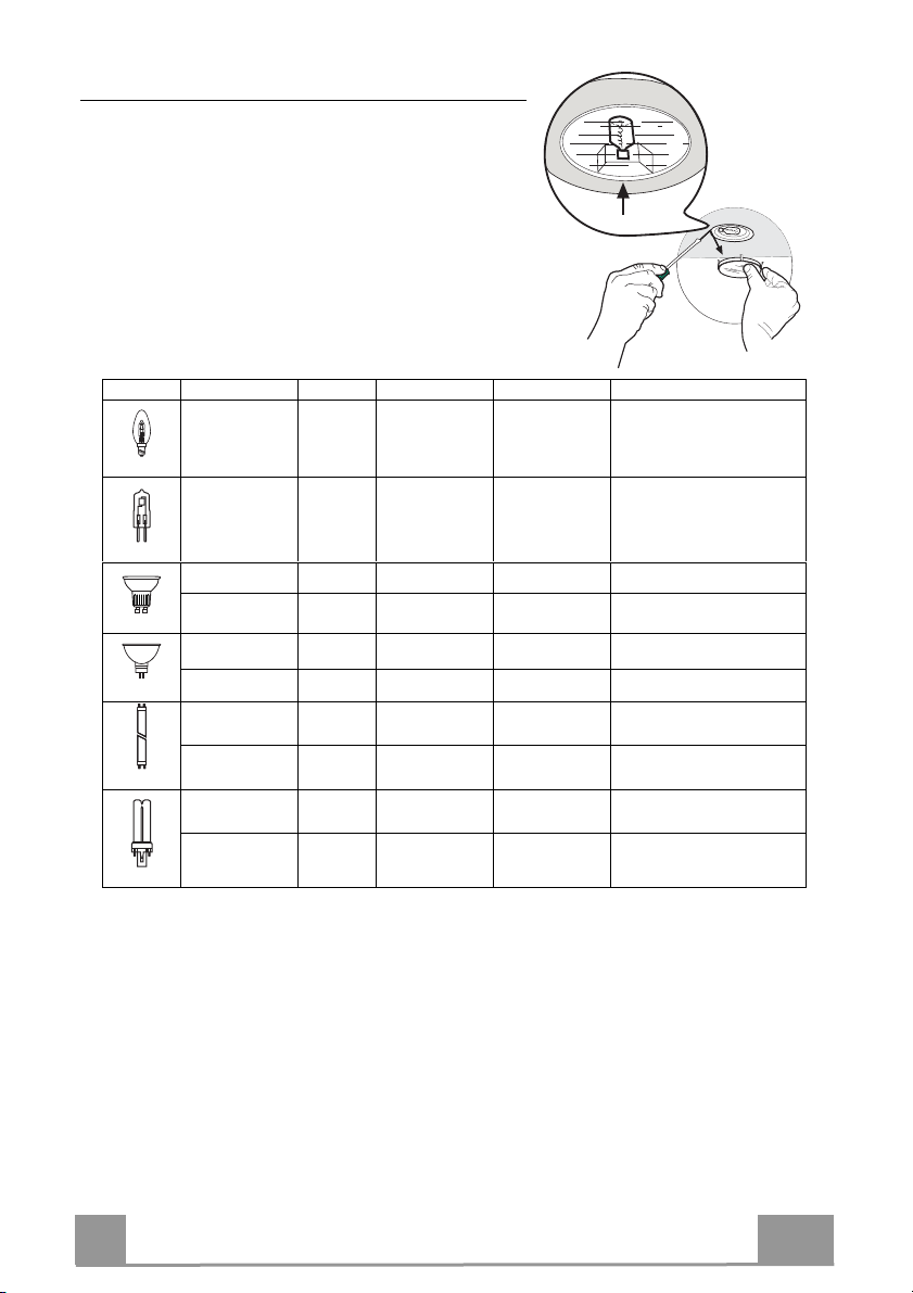
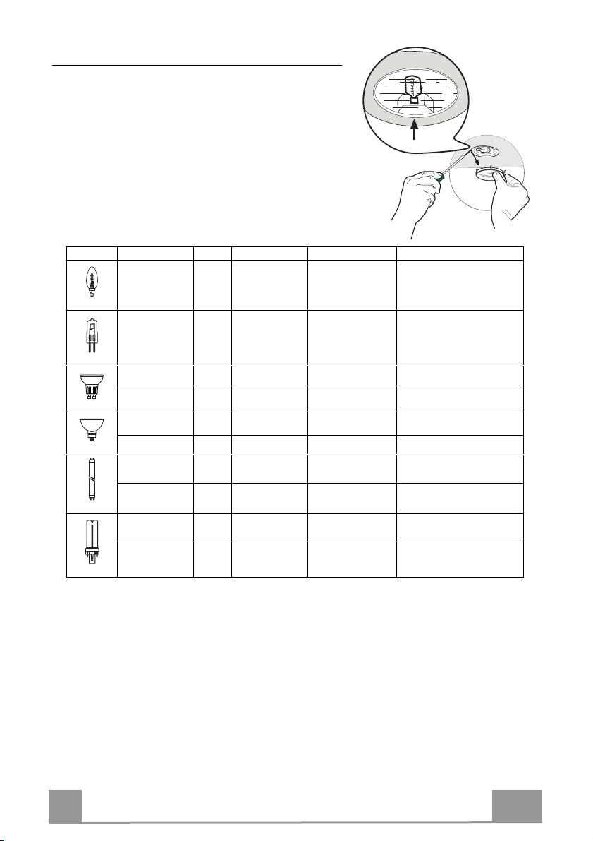
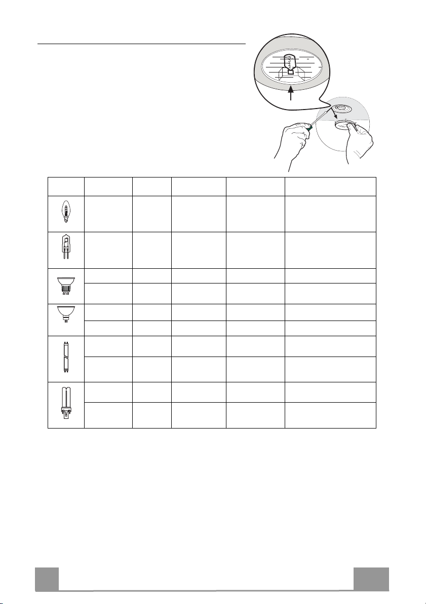
Lighting
LIGHT REPLACEMENT
20 W halogen light.
• Remove the snap-on lamp cover by levering it from
under the metal ring, supporting it with one hand.
• Remove the halogen lamp from the lamp holder by
pulling gently.
• Replace the lamp with a new one of the same type,
making sure that you insert the two pins properly into
the housings on the lamp holder.
• Replace the snap-on lamp cover.
Lamp Power (W) Socket Voltage (V) Dimension (mm) ILCOS Code
28 E14 220 – 240 104 x 35
20 G4 12 33 x 9 HSG/C/UB-20-12-G4
35 GU10 230 51 x 50,7 HAGS-35-230-GU10-51/40
50 GU10 230 51 x 50,7 HAGS-35-230-GU10-51/20
20 GU4 12 40 x 35 HRGS-20-12-GU4-35/30
20 GU5.3 12 46 x 51 HRGS-20-12-GU5.3-50/10
16 G13 95 720 x 26
18 G13 57 589,8 x 26
9 G23
11 G23
60 (lamp)
220-240 (starter)
91 (lamp)
220-240 (starter)
167 x 28 FSD-9/27/1B-I-G23
235,8 x 28 FSD-11/40/1B-I-G23
HSGSB/C/UB-28-220/240-E14
FD--16/40/1B-E--G13--26/720
FD--18/40/1B--E--G13--26/600
EN
14
1
Page 15
CONSEILS ET SUGGESTIONS
Les instructions pour l’utilisation se réfèrent aux différents modèles de cet
appareil. Par conséquent, certaines descriptions de caractéristiques
particulières pourraient ne pas appartenir spécifiquement à cet appareil.
INSTALLATION
• En aucun cas le fabricant ne peut être tenu pour responsable d’éventuels
dommages dus à une installation ou à une utilisation impropre.
• La distance de sécurité minimum entre le plan de
cuisson et la hotte aspirante est de 650 mm (certains
modèles peuvent être installés à une hauteur inférieure ;
voir le paragraphe concernant les dimensions de travail
et l’installation).
• Assurez-vous que la tension de votre secteur correspond
à celle indiquée sur la plaque des données appliquée à
l’intérieur de la hotte.
• Pour les appareils de Classe I, s’assurer que l’installation électrique de votre
intérieur dispose d’une mise à la terre adéquate.
Relier l’aspirateur au conduit de cheminée avec un tube d’un diamètre minimum
de 120 mm. Le parcours des fumées doit être le plus court possible.
• Ne pas relier la hotte aspirante aux conduits de cheminée qui acheminent les
fumées de combustion (par exemple de chaudières, de cheminées, etc.).
• Si vous utilisez l’aspirateur en combinaison avec des
appareils non électriques (par ex. appareils à gaz), vous
devez garantir un degré d’aération suffisant dans la pièce,
afin d’empêcher le retour du flux des gaz de sortie. La
cuisine doit présenter une ouverture communiquant
directement vers l’extérieur pour garantir l’amenée d’air
propre. Si vous utilisez la hotte de cuisine en combinaison avec des appareils
non alimentés à l’électricité, la pression négative dans la pièce ne doit pas
dépasser 0,04 mbar afin d’éviter que la hotte ne réaspire les fumées dans la
pièce.
• Si le cordon d’alimentation est endommagé, veuillez le faire remplacer par le
fabricant ou par un service après-vente agréé pour éviter tout risque d’accident.
2°
FR
15
1
Page 16
• Si les instructions d’installation du plan de cuisson à gaz spécifient une
distance supérieure à celle indiquée ci-dessus, veuillez impérativement en
tenir compte. Toutes les normes concernant l’évacuation de l’air doivent être
respectées.
• Utiliser exclusivement des vis et des petites pièces du type adapté pour la
hotte.
Attention : toute installation des vis et des dispositifs de fixation non
conforme aux présentes instructions peut entraîner des risques de
décharges électriques.
• Brancher la hotte à l’alimentation de secteur avec un interrupteur bipolaire
ayant une ouverture des contacts d’au moins 3 mm.
UTILISATION
• Cette hotte aspirante a été conçue exclusivement pour un usage
domestique, dans le but d’éliminer les odeurs de cuisine.
• Ne jamais utiliser la hotte pour des objectifs différents de ceux pour lesquels
elle a été conçue.
• Ne jamais laisser un feu vif allumé sous la hotte lorsque celle-ci est en
fonction.
• Régler l’intensité du feu de manière à l’orienter exclusivement vers le fond
de la casserole, en vous assurant qu’il ne déborde pas sur les côtés.
• Contrôler constamment les friteuses durant leur
utilisation : l’huile surchauffée risque de s’incendier.
• Ne pas flamber des mets sous la hotte : sous risque
de provoquer un incendie.
• Cet appareil n’est pas destiné à être utilisé par des
enfants d’un âge inférieur à 8 ans, ni par des personnes dont les capacités
physiques, sensorielles ou mentales sont diminuées ou qui ont une
expérience et des connaissances insuffisantes, à moins que ces enfants ou
ces personnes ne soient attentivement surveillés et instruits sur la manière
d’utiliser cet appareil en sécurité et sur les dangers que cela comporte.
Assurez-vous que les enfants ne jouent pas avec cet appareil. Le nettoyage
et l’entretien de la part de l’utilisateur ne doivent pas être effectués par des
enfants, à moins que ce ne soit sous la surveillance d’une personne
responsable.
FR
16
1
Page 17

• ATTENTION : les parties accessibles peuvent devenir très chaudes durant
l’utilisation des appareils de cuisson.
ENTRETIEN
• Avant d’effectuer toute opération de nettoyage et d’entretien, éteindre ou
débrancher l’appareil du secteur.
• Nettoyer et/ou remplacer les filtres après le délai indiqué (danger
d’incendie).
• Nettoyer les filtres à graisse tous les 2 mois de fonctionnement ou plus
souvent en cas d’utilisation particulièrement intense. Ces filtres peuvent être
lavés au lave-vaisselle.
• Le filtre à charbon actif ne peut être ni lavé ni régénéré et il doit être
remplacé environ tous les 4 mois de fonctionnement ou plus souvent en cas
d’utilisation particulièrement intense.
• Effectuer le nettoyage selon les instructions, sous risque d'incendie.
• Nettoyer la hotte avec un chiffon humide et un détergent liquide neutre.
Le symbole marqué sur le produit ou sur son emballage indique que ce
produit ne peut pas être éliminé comme déchet ménager normal. Lorsque ce
produit doit être éliminé, veuillez le remettre à un centre de collecte prévu pour
le recyclage du matériel électrique et électronique. En vous assurant que cet
appareil est éliminé correctement, vous participez à prévenir des
conséquences potentiellement négatives pour l'environnement et pour la
santé, qui risqueraient de se présenter en cas d’élimination inappropriée. Pour
toute information supplémentaire sur le recyclage de ce produit, contactez
votre municipalité, votre déchetterie locale ou le magasin où vous avez acheté
ce produit.
FR
17
1
Page 18

CARACTERISTIQUES
Encombrement
1000
545
598-698-798-898-1198
300
150
108
470 45
730
260
Composants
Réf. Q.té Composants de Produit
1 1 Corps Hotte équipé de:Commandes, Lumière, Groupe
Ventilateur,Filtres
2 1 Cheminée Télescopique formée de :
2.1 1 Cheminée Supérieure
2.2 1 Cheminée Inférieure
9 1 Flasque de Réduction ø 150-120 mm
15 1 Raccord Sortie Air
Réf. Q.té Composants pour l ’installation
7.2.1 2 Brides Fixation Cheminée Supérieure
11 6 Chevilles
12a 6 Vis 4,2 x 44,4
12c 6 Vis 2,9 x 9,5
Q.té Documentation
1 Manuel d’instructions
Min.
650mm
42
81
Min.
650mm
12b
64
FR
18
1
Page 19
INSTALLATION
Perçage Paroi et Fixation Brides
7.2.1
1÷2
X
11
12a
116
116
305
650 min.
Tracer sur la paroi:
• une ligne verticale allant jusqu’au plafond ou à la limite supérieure, au centre de la zone
prévue pour le montage de la hotte;
• une ligne horizontale à 650 mm min. au-dessus du plan de cuisson.
• Poser comme indiqué une bride 7.2.1 sur la paroi à 1-2 mm du plafond ou de la limite supérieure, en alignant son centre (découpes) sur la ligne verticale de repère.
• Marquer les centres des trous rainurés de la bride.
• Poser comme indiqué la bride 7.2.1 à X mm sous la première bride (X = hauteur cheminée
supérieure fournie), en alignant son centre (découpes) sur la ligne verticale de repère.
• Marquer les centres des trous rainurés de la bride.
• Marquer comme indiqué, un point de référence à 116 mm de la ligne verticale de repère, et
305 mm au-dessus de la ligne horizontale de repère.
• Répéter cette opération sur le côté opposé.
• Percer de ø 8 mm tous les points marqués.
• Insérer les chevilles 11 dans les trous.
• Fixer les brides en utilisant les vis 12a (4,2 x 44,4) fournies.
• Visser les 2 vis 12a (4,2 x 44,4) fournies dans les trous de fixation du corps hotte, en laissant
un espace de 5-6 mm entre le mur et la tête de la vis.
FR
19
1
Page 20
Montage Corps Hotte
12a
Vr
9
ø 120ø 150
• Avant d’accrocher le corps hotte, serrer les deux vis Vr situées
sur les points d’accrochage du corps hotte.
• Accrocher le corps hotte aux vis 12a prévues à cet effet.
• Serrer définitivement les vis 12a de support.
• Agir sur les vis Vr pour niveler le corps hotte.
Branchements
SORTIE AIR VERSION ASPIRANTE
Pour l’installation en version aspirante, relier la hotte au tube de
sortie au moyen d’un tube rigide ou flexible de ø 150 ou 120 mm
dont le choix est laissé à l’installateur.
• Pour la liaison avec le tube ø120 mm, insérer la buse de réduction 9 sur la sortie du corps de la hotte.
• Fixer le tube avec des colliers serre-tube appropriés. Le
matériel nécessaire n’est pas fourni.
• Retirer les filtres anti-odeur à charbon actif éventuels.
SORTIE AIR VERSION FILTRANTE
• Desserrer les 2 vis de fixation du support supérieur 7.2.1.
• Visser à sa place le raccord de sortie de l’air 15 avec les 2 vis
précédemment retirées.
• Relier le raccord 15 à la sortie du corps de hotte au moyen d’un
tube rigide ou flexible de ø 150 mm, au choix de l'installateur.
• S’assurer de la présence du filtre anti-odeur au charbon actif.
FR
2
20
Page 21

BRANCHEMENT ELECTRIQUE
• Brancher la hotte sur le secteur en interposant un interrupteur
bipolaire avec ouverture des contacts d’au moins 3 mm.
• Enlever les filtres à graisse (voir § "Entretien") et s'assurer que
le connecteur du câble d'alimentation soit bien branché dans la
prise du diffuseur.
Montage Cheminée
Cheminée supérieure
• Elargir légèrement les deux bords latéraux, et les accrocher
derrières les brides 7.2.1 ; refermer jusqu’en butée.
• Fixer latéralement aux brides à l’aide des 4 vis 12c fournies.
• S’assurer que la sortie des rallonges raccord se trouve au
niveau des bouches de la cheminée.
Cheminée inférieure
• Elargir légèrement les deux bords latéraux de la cheminée et
les accrocher entre la cheminée supérieure et la paroi; refermer
jusqu’en butée.
• Fixer latéralement la partie inférieure au corps de la hotte, à
l’aide des deux 2 vis 12c fournies.
12b
FR
21
2
Page 22

UTILISATION
L
T1 T2 T3 T4
L
T1 T4
Touche Led Fonction
L
- Allume/Éteint les lumières à la luminosité maximum.
T1
Fixe Démarre/Coupe le moteur à la première vitesse.
T2
Fixe Démarre le moteur à la deuxième vitesse.
Garder la touche appuyée pendant environ 5 secondes, lorsque toutes les
T3
Fixe Démarre le moteur à la troisième vitesse.
Garder la touche appuyée pendant environ 3 secondes, lorsque toutes les
T4
Fixe Démarre le moteur à la vitesse INTENSIVE.
Garder la touche appuyée pendant environ 5 secondes pour valider la
S1
Fixe Signale l’alarme saturation filtres à graisse métalliques et la nécessité de les
Clignotante Lorsque l’alarme de saturation du filtre anti-odeur est activée, c’est l’indice
T3S1T2
charges sont éteintes (Moteur+ Éclairage), l’alarme des filtres au charbon
actif s’active et la led correspondante clignotera 2 fois.
Pour la désactiver, appuyer de nouveau sur la touche pendant 5 secondes.
La led correspondante clignotera 1 fois.
charges sont éteintes (Moteur+ Éclairage), le reset est effectué et la led S1
correspondante clignotera 3 fois.
Cette vitesse est temporisée à 6 minutes. Après ce délai, Le système retourne automatiquement à la vitesse sélectionnée. Si activée avec le moteur
à l’arrêt, à la fin du délai le système passe en mode OFF.
télécommande. La led correspondante clignotera 2 fois.
Garder la touche appuyée pendant 5 secondes pour invalider la
télécommande. La led correspondante clignotera 1 seule fois
laver. L’alarme entre en fonction après 100 heures de travail effectif de la
hotte. (Reset voir paragraphe Entretien)
que le filtre doit être remplacé. Laver aussi les filtres à graisse métalliques.
L’alarme de saturation filtre anti-odeur au charbon actif entre en fonction
après 200 heures de travail effectif de la hotte. (Activation et Reset voir
paragraphe Entretien)
S1
Tableau de commande
L
T1
T2
T3
T4
S1
FR
22
2
Page 23

ENTRETIEN
TELECOMMANDE (FOURNIE SUR DEMANDE)
Il est possible de commander cet appareil au moyen d’une télécommande, alimentée avec des piles alcalines zinc-charbon 1,5 V
du type standard LR03-AAA (non compris).
• Ne pas ranger la télécommande à proximité de sources de chaleur.
• Ne pas jeter les piles; il faut les déposer dans les récipients de
récolte spécialement prévus à cet effet.
Filtres à graisse métalliques
Ils peuvent être lavés au lave-vaisselle et doivent être lavés quand
la led S1 s’allume ou au moins tous les 2 mois d’utilisation ou
plus fréquemment en cas d’utilisation particulièrement intensive.
NETTOYAGE FILTRES
Reset du signal d'alarme
• Éteindre les lumières et le moteur d’aspiration.
• Appuyer sur la touche T3 pendant au moins 3 secondes jusqu’au triple clignotement de confirmation de la led.
Nettoyage filtres
• Retirer le filtre en le poussant vers l’arrière du groupe et en
tirant en même temps vers le bas.
• Laver le filtre en évitant de le plier, et le laisser sécher avant de
le remonter (tout changement de couleur de la surface du filtre,
susceptible de se produire avec le temps, ne nuit en rien à
l’efficacité de ce dernier).
• Le remonter en faisant attention de garder la poignée vers la
partie visible externe.
FR
23
2
Page 24

Filtres anti-odeur à charbon actif (version filtrante)
Il n’est ni lavable, ni régénérable. Le remplacer lorsque la led S1 clignote ou au moins tous les
4 mois. Le signal d’alarme, si préalablement activé, se vérifie seulement lorsque le moteur
d’aspiration est en marche.
Activation du signal d’alarme
• Dans les hottes en version filtrante, activer le signal d’alarme de saturation filtres au
moment de l’installation ou après.
• Éteindre les lumières et le moteur d’aspiration.
• Appuyer pendant 5 secondes sur la touche T2 jusqu’à ce que la led de confirmation
clignote :
REMPLACEMENT
Reset du signal d'alarme
• Éteindre les lumières et le moteur d’aspiration.
• Appuyer sur la touche T3 pendant au moins 3 secondes
jusqu’au triple clignotement de confirmation de la led.
Remplacement du filtre
• Retirer le filtre à graisse
• Retirer le filtre anti-odeur au charbon actif colmaté, en agissant
sur les crochets prévus à cet effet.
• Monter le nouveau filtre anti-odeur au charbon actif.
• Remonter le filtre à graisse
FR
24
2
Page 25
Eclairage
REMPLACEMENT LAMPES
Lampe halogène de 20 W.
• Enlever le dispositif métallique de blocage du verre
par encliquetage en exerçant une pression sous
l’embout en le soutenant d’une main.
• Extraire la lampe du support
• Remplacer la lampe par une nouvelle ayant le mêmes
caractéristiques, en prenant soin d'insérer correctement les deux fiches dans le support.
• Remonter le dispositif de blocage du verre par encliquetage.
Ampoule Absorption (W) Culot Voltage (V) Dimensions (mm) Code ILCOS
28 E14 220 – 240 104 x 35
20 G4 12 33 x 9 HSG/C/UB-20-12-G4
35 GU10 230 51 x 50,7 HAGS-35-230-GU10-51/40
50 GU10 230 51 x 50,7 HAGS-35-230-GU10-51/20
20 GU4 12 40 x 35 HRGS-20-12-GU4-35/30
20 GU5.3 12 46 x 51 HRGS-20-12-GU5.3-50/10
16 G13 95 720 x 26
18 G13 57 589,8 x 26
9 G23
11 G23
60 (ampoule)
220-240 (starter)
91 (ampoule)
220-240 (starter)
167 x 28 FSD-9/27/1B-I-G23
235,8 x 28 FSD-11/40/1B-I-G23
HSGSB/C/UB-28-220/240-E14
FD--16/40/1B-E--G13--26/720
FD--18/40/1B--E--G13--26/600
FR
25
2
Page 26
EMPFEHLUNGEN UND HINWEISE
Diese Gebrauchsanleitungen beziehen sich auf die verschiedenen Modelle
der Abzugshaube. Darum kann es möglich sein, dass die Beschreibung
bestimmter Merkmale für das vorliegende Gerät nicht zutrifft.
INSTALLATION
• Der Hersteller haftet nicht für etwaige Schäden, die durch die fehlerhafte
Installation oder falschen Gebrauch entstehen könnten.
• Der min. Sicherheitsabstand zwischen Kochfeld
und Abzugshaube beträgt 650 mm (einige Modelle
können auch niedriger installiert werden; siehe
Absatz Installation).
• Kontrollieren Sie, ob die Netzspannung den Daten
des Typenschilds im Innern der Haube entspricht.
• Für Geräte der Klasse I muss kontrolliert werden,
ob das häusliche Versorgungsnetz korrekt geerdet
ist.
Die Absaughaube mit Hilfe eines Rohrs mit einem Mindestdurchmesser von
120 mm mit dem Rauchabzug verbinden. Der Verlauf des Rauchabzugs soll
so kurz wie möglich sein.
• Die Abzugshaube darf nicht an einen Schacht angeschlossen werden, in den
Rauchgase geleitet werden (z. B. von Heizkessel, Kaminen, usw.).
• Falls in dem Raum neben dem Abzug auch nicht
mit Strom betriebene Geräte (zum Beispiel
Gasgeräte) eingesetzt werden, muss für eine
ausreichende Belüftung gesorgt werden, damit der
Rückfluss der Abgase verhindert wird. Die Küche
muss eine direkte Öffnung nach Außen aufweisen,
damit ein ausreichender Luftaustausch
gewährleistet wird. Wird die Abzugshaube
zusammen mit nicht mit Strom betriebenen Geräte eingesetzt, darf der
Unterdruck im Raum 0,04 mbar nicht überschreiten, damit die Abgase nicht
wieder angesaugt werden.
• Schadhafte Kabel müssen durch den Hersteller oder vom Kundendienst
ausgewechselt werden, damit jedes Risiko ausgeschlossen wird.
2°
DE
26
2
Page 27
• Falls die Montageanweisungen für die gasbetriebene Kochmulde einen
größeren Abstand vorschreiben, als der oben angegebene, muss diese
Vorgabe befolgt werden. Es sind sämtliche Abluftvorschriften zu beachten.
• Nur für die Abzugshaube geeignete Schrauben und Kleinteile verwenden.
Achtung: Werden die Schrauben und Befestigungselemente nicht
entsprechend der vorliegenden Anleitungen verwendet, besteht
Stromschlaggefahr.
• Die Abzugshaube mittels zweipoligem Schalter mit einer Öffnung der
Kontakte von mindestens 3 mm an das Netz anschließen.
GEBRAUCH
• Die Abzugshaube wurde ausschließlich für den häuslichen Gebrauch
entwickelt, um Kochdünste zu beseitigen.
• Die Haube darf nur für die ihr zugedachten Zwecke benutzt werden.
• Unter der eingeschalteten Haube keine offenen Flammen benutzen.
• Die Flamme so regulieren, dass sie nicht über den Boden des Kochgeschirrs
hinausreicht.
• Fritteusen müssen während des Gebrauchs
ständig überwacht werden: überhitztes Öl könnte
sich entzünden.
• Auf keinen Fall unter der Haube flambieren:
Brandgefahr.
• Kinder ab 8 Jahren und Personen mit
eingeschränkten physischen, sensorischen oder psychischen Fähigkeiten,
oder mit mangelnden Erfahrungen oder Kenntnissen dürfen nicht mit dem
Gerät umgehen, es sei denn, sie werden von einer für ihre Sicherheit
verantwortlichen Person beaufsichtigt oder angeleitet. Sicherstellen, dass
Kinder nicht mit dem Gerät herumspielen können. Reinigungs- und
Wartungsarbeiten dürfen nicht von unbeaufsichtigten Kindern durchgeführt
werden.
DE
27
2
Page 28
• ACHTUNG: Die zugänglichen Teile können während des Gebrauchs der
Kochgeräte sehr heiß werden.
WARTUNG
• Vor Reinigungs- oder Wartungsarbeiten am Gerät, muss dieses
ausgeschaltet und spannungslos gemacht werden.
• Die Filter stets nach den angegebenen Intervallen reinigen oder
auswechseln (Brandgefahr).
• Die Fettfilter sind alle 2 Monate oder bei intensiver Nutzung öfter zu reinigen
und können in der Spülmaschine gespült werden.
• Der Aktivkohlefilter ist weder waschbar, noch regenerierbar und muss bei
normalem Betrieb zirka alle 4 Monate oder auch öfter ausgewechselt
werden, je nach Intensität des Gebrauchs.
• „Wenn die Reinigung nicht nach den Anweisungen durchgeführt wird,
besteht Brandgefahr“.
• Die Haube mit einem feuchten Lappen und einem neutralen
Reinigungsmittel abwischen.
Das Symbol am Produkt oder auf der Verpackung weist darauf hin, dass
das Gerät nicht als normaler Hausmüll entsorgt werden darf. Das ausrangierte
Gerät muss vielmehr bei einer speziellen Sammelstelle für elektrische und
elektronische Geräte abgegeben werden. Mit der vorschriftsmäßigen
Entsorgung des Gerätes trägt der Benutzer dazu bei, schädliche
Auswirkungen auf Umwelt und Gesundheit zu vermeiden. Weitere
Informationen zum Recycling dieses Produktes können bei der zuständigen
Behörde, der örtlichen Abfallbeseitigung oder bei dem Händler, der das Gerät
verkauft hat, eingeholt werden.
DE
28
2
Page 29
CHARAKTERISTIKEN
Platzbedarf
1000
545
598-698-798-898-1198
300
150
108
470 45
730
260
Komponenten
Pos. St. Produktkomponenten
1 1 Haubenkörper mit Schaltern, Beleuchtung, Gebläse-
gruppe, Filter
2 1 Teleskopkamin bestehend aus:
2.1 1 oberer Kaminteil
2.2 1 unterer Kaminteil
9 1 Reduzierflansch ø 150-120 mm
15 1 Luftaustritt-Anschlussstück
Pos. St. Montagekomponenten
7.2.1 2 Befestigungsbügel oberer Kaminteil
11 6 Dübel
12a 6 Schrauben 4,2 x 44,4
12c 6 Schrauben 2,9 x 9,5
St. Dokumentation
1 Bedienungsanleitung
Min.
650mm
42
81
Min.
650mm
12b
64
DE
29
2
Page 30
MONTAGE
Bohren der Befestigungslöcher und Fixieren der Befestigungsbügel
7.2.1
1÷2
X
12a
11
116
116
305
650 min.
Nachstehende Linien an die Wand zeichnen:
• eine vertikale Linie bis zur Decke oder oberen Begrenzung, und zwar in der Mitte des Bereiches, in dem die Haube montiert werden soll;
• eine horizontale Linie mit einem minimalen Abstand von 650 mm zur Kochfläche.
• Einen Bügel 7.2.1 zirka 1-2 mm unter der Decke oder oberen Begrenzung an die Wand legen und seinen Mittelpunkt (Einschnitte) auf die vertikale Bezugslinie ausrichten.
• Die Mitte der beiden Bügellöcher an der Wand markieren.
• Den zweiten Bügel 7.2.1 an die Wand legen, wobei ein Abstand X mm vom oberen Bügel
einzuhalten ist (X = Höhe des jeweiligen oberen Kaminteils); den Mittelpunkt (Einschnitte)
auf die vertikale Bezugslinie ausrichten.
• Die Mitte der Bügellöcher an der Wand markieren.
• Wie beschrieben einen Bezugspunkt 116 mm von der vertikalen Bezugslinie und 305 mm
oberhalb der horizontalen Bezugslinie kennzeichnen.
• Gleichermaßen an der gegenüberliegenden Seite vorgehen.
• Mit einem Bohrer ø 8 mm die markierten Punkte bohren.
• Die Dübel 11 in die Bohrungen einfügen.
• Die Bügel mit den mitgelieferten Schrauben 12a (4,2 x 44,4) fixieren.
• 2 der mitgelieferten Schrauben 12a (4,2 x 44,4) bei den Befestigungslöchern des Haubenkörpers einschrauben, wobei zwischen Wand und Schraubenkopf ein Freiraum von 5-6 mm
zu belassen ist.
DE
30
3
Page 31

Montage des Haubenkörpers
12a
Vr
9
ø 120ø 150
• Bevor der Haubenkörper eingehakt wird, die 2 Schrauben Vr
bei den Haubenkörper-Anhakpunkten festziehen.
• Den Haubenkörper bei den Schrauben 12a einhängen.
• Die Halteschrauben 12a definitiv festziehen.
• Den Haubenkörper mit Hilfe der Schrauben Vr ausrichten.
Anschluss im Abluftbetrieb
Bei Abluftbetrieb kann die Haube vom Installateur wahlweise
mittels Rohr oder Schlauch (ø 150 oder 120 mm) an die Außenrohrleitung angeschlossen werden.
• Bei Verwendung eines Anschlussrohres ø 120 den Reduzierflansch 9 am Haubenaustritt anbringen.
• Das Rohr mit geeigneten Rohrschellen fixieren. Das hierzu
erforderliche Material wird nicht mitgeliefert.
• Eventuell vorhandene Aktivkohlefilter entnehmen.
LUFTAUSTRITT BEI DER UMLUFTVERSION
• Die beiden Befestigungsschrauben des oberen Bügels 7.2.1.
aufschrauben.
• An ihrer Stelle mit den zuvor entfernten Schrauben ein
Anschlussstück an die Abzugsöffnung 15 anschrauben.
• Den Anschluss 15 mittels eines starren oder flexiblen Rohrs
mit ø150 mm, das vom Installateur ausgewählt wird, an den
Austritt des Haubenkörpers anschließen.
• Sicherstellen, dass der Aktivkohlefilter zur Geruchsbindung
vorhanden ist.
DE
3
31
Page 32

ELEKTROANSCHLUSS
• Bei Anschluss der Haube an das Stromnetz muss ein zweipoliger Schalter mit einem Öffnungsweg von mindestens 3 mm
zwischengeschaltet werden.
• Entfernen Sie die Fettfilter (s. Abschnitt „Wartung“) und versichern Sie sich, daß die Kabelverbindung in die Steckdose des
Gebläses einwandfrei eingesteckt wird.
Kaminmontage
Oberer Kaminteil
• Die beiden seitlichen Schenkel leicht auseinanderbiegen, hinter
den Bügeln 7.2.1 einhängen und bis zum Anschlag wieder
schließen.
• Bei den Bügeln 7.2.1 mit Hilfe der 4 mitgelieferten Schrauben
12c fixieren.
• Überprüfen, ob die Verlängerungen mit den entsprechenden
Kaminstutzen übereinstimmen.
Unterer Kaminteil
• Die beiden seitlichen Schenkel des Kaminteils leicht auseinander biegen, zwischen dem oberen Kaminteil und der Wand
einhängen und bis zum Anschlag wieder schließen.
• Den unteren Teil seitlich am Haubenkörper mit 2 der mitgelieferten Schrauben 12c fixieren.
12b
DE
32
3
Page 33

BEDIENUNG
S1
L
T1 T2 T3 T4
L
T1 T4
T3S1T2
Schalttafel
Taste LED Funktion
L
-
T1
Bleibend Schaltet den Motor bei der ersten Betriebsgeschwindigkeit ein/aus.
T2
Bleibend Schaltet den Motor bei der zweiten Betriebsgeschwindigkeit ein.
Schaltet die Beleuchtung bei maximaler Intensität ein/aus.
Mit zirka 5 Sekunden langem Gedrückthalten der Taste bei abgeschalteten
Verbrauchern (Motor+Licht) wird der Alarm für aktive Aktivkohlefilter
aktiviert und die entsprechende LED blinkt zweimal.
Zum Abstellen die Taste erneut 5 Sekunden lang drücken, die
entsprechende LED blinkt ein Mal.
T3
Bleibend Schaltet den Motor bei der dritten Betriebsgeschwindigkeit ein.
Mit zirka 3 Sekunden langem Gedrückthalten der Taste bei abgeschalteten
Verbrauchern (Motor+Licht) erfolgt ein Reset und die LED S1 blinkt drei
Mal.
T4
Bleibend Schaltet den Motor bei Intensivgeschwindigkeit ein.
Diese Geschwindigkeit ist auf 6 Minuten zeitgeregelt. Nach Ablauf dieser
Zeit kehrt das System zu der zuvor eingestellten Geschwindigkeit zurück.
Wird sie bei abgestelltem Motor aktiviert, wird nach Ablauf der Zeit zum
Betriebsmodus OFF übergegangen.
Mit 5 Sekunden langem Drücken wird die Fernbedienung aktiviert und die
entsprechende LED blinkt zwei Mal.
Mit 5 Sekunden langem Drücken wird die Fernbedienung deaktiviert und
die entsprechende LED blinkt nur ein Mal.
S1
Bleibend Meldet den Alarm für Sättigung der Metallfettfilter und die Notwendigkeit,
diese zu waschen. Dieser Alarm wird nach 100 effektiven Betriebsstunden
der Abzugshaube ausgelöst. (Reset siehe Absatz Wartung).
Blinkend Meldet, sofern aktiviert, den Alarm für Sättigung des Aktivkohlefilters, der
ausgewechselt werden muss; auch die Metallfettfilter müssen gewaschen
werden. Der Alarm für Sättigung des Aktivkohlefilters wird nach 200
effektiven Betriebsstunden der Abzugshaube ausgelöst. (Aktivierung und
Reset siehe Absatz Wartung).
L
T1
T2
T3
T4
S1
DE
33
3
Page 34
WARTUNG
FERNBEDIENUNG (OPTION)
Dieses Gerät kann mit einer Fernbedienung gesteuert werden,
welche mit alkalischen Zink-Kohle-Batterien 1,5 V des Standardtyps LR03-AAA versorgt wird (nicht im Lieferumfang enthalten).
• Die Fernbedienung nicht in die Nähe von Hitzequellen legen.
• Batterien müssen vorschriftsmäßig entsorgt werden.
Metallfettfilter
Die Fettfilter sind spülmaschinengeeignet und müssen gewaschen
werden, sobald sich die LED S1 einschaltet, oder mindestens alle
2 Monate, oder auch öfter, je nach Intensität des Gebrauchs.
REINIGUNG DER FILTER
Reset des Alarmsignals
• Die Beleuchtung und den Absaugmotor abstellen.
• Die Taste T3 mindestens 3 Sekunden lang drücken, bis der
Vorgang durch dreimaliges Blinken der LED bestätigt wird.
Reinigung der Filter
• Den Filter zu dem hinteren Teil der Gruppe schieben und
gleichzeitig nach unten ziehen.
• Den Filter waschen, ohne ihn zu verbiegen, und vor dem Wiedereinbau trocknen lassen (die Farbe der Filteroberfläche kann
sich mit der Zeit verändern, was aber die Wirksamkeit keinesfalls beeinträchtigt.)
• Nun den Filter wieder einbauen, so dass der Griff nach der äußeren Sichtseite zeigt.
DE
34
3
Page 35

Aktivkohle-Geruchsfilter (Umluftvariante)
Der Aktivkohlefilter ist weder waschbar, noch regenerierbar und muss ausgewechselt werden,
wenn die LED S1 blinkt, oder mindestens alle 4 Monate. Die Alarmmeldung, wenn zuvor aktiviert, erfolgt nur, wenn der Absaugmotor zugeschaltet ist.
Aktivierung des Alarmsignals
• Bei der Umluftvariante sollte die Alarmanzeige für die Filtersättigung bei der Erstinbetrieb-
nahme aktiviert werden. Zudem kann sie nachträglich wie folgt aktiviert werden:
• Die Beleuchtung und den Absaugmotor abstellen.
• 5 Sekunden lang die Taste T2 drücken, bis die LED zur Bestätigung blinkt:
AUSWECHSELN
Reset des Alarmsignals
• Die Beleuchtung und den Absaugmotor abstellen.
• Die Taste T3 mindestens 3 Sekunden lang drücken, bis der
Vorgang durch dreimaliges Blinken der LED bestätigt wird.
Auswechseln des Filters
• Den Fettfilter ausbauen.
• Den gesättigten Aktivkohle-Geruchsfilter aushaken.
• Den neuen Filter in seinem Sitz einhaken.
• Den Fettfilter wieder einbauen.
DE
35
3
Page 36

Beleuchtung
AUSWECHSELN DER LAMPEN
Halogenlampe 20 W
• Zum Auswechseln der Lampen, die Glashalterung
aus Metall durch Anheben der Zwinge entfernen und
die Halterung dabei mit einer Hand stützen.
• Die Lampe aus der Halterung nehmen.
• Die Lampe durch eine gleichwertige ersetzen und
beim Wiedereinsetzen darauf achten, daß die beiden
Steckerstifte vorschriftsmäßig in die Lampenfassung
eingeführt werden.
• Die Glashalterung wieder eindrücken.
Lampe Leistung (W) Fassung Spannung (V) Größe (mm) ILCOS-Code
28 E14 220 – 240 104 x 35
20 G4 12 33 x 9 HSG/C/UB-20-12-G4
35 GU10 230 51 x 50,7 HAGS-35-230-GU10-51/40
50 GU10 230 51 x 50,7 HAGS-35-230-GU10-51/20
20 GU4 12 40 x 35 HRGS-20-12-GU4-35/30
20 GU5.3 12 46 x 51 HRGS-20-12-GU5.3-50/10
16 G13 95 720 x 26
18 G13 57 589,8 x 26
9 G23
11 G23
60 (Lampe)
220-240 (Starter)
91 (Lampe)
220-240 (Starter)
167 x 28 FSD-9/27/1B-I-G23
235,8 x 28 FSD-11/40/1B-I-G23
HSGSB/C/UB-28-220/240-E14
FD--16/40/1B-E--G13--26/720
FD--18/40/1B--E--G13--26/600
DE
36
3
Page 37

CONSEJOS Y SUGERENCIAS
Las instrucciones de uso se aplican a varios modelos de este aparato. Por lo
tanto, usted puede encontrar descripciones de características individuales que no
pertenecen a su aparato en concreto.
INSTALACIÓN
• El fabricante no se hace responsable de los daños provocados por una instalación
o uso indebido.
• La distancia mínima de seguridad entre el plano de
cocción y la campana extractora es de 650 mm
(algunos modelos pueden ser instalados a una altura
inferior; véase el párrafo relativo a las dimensiones de
trabajo y la instalación).
• Compruebe que la tensión de alimentación corresponda
a la indicada en la placa de datos colocada en el interior
de la campana.
• Para los aparatos de Clase I, compruebe que la red
eléctrica doméstica tenga una conexión a tierra adecuada.
Conecte la campana extractora al conducto de humo a través de un tubo con un
diámetro mínimo de 120 mm. La trayectoria del humo debe ser lo más corta
posible.
• No conecte la campana extractora a los conductos de humo que transportan humo
de combustión (ej. calderas, chimeneas, etc.).
• Si la campana extractora se utiliza en combinación con
aparatos no eléctricos (por ejemplo, aparatos de gas),
debe garantizarse un grado suficiente de ventilación en el
recinto para evitar el retorno del flujo de los gases de
escape. La cocina debe tener una abertura comunicante
directamente con el exterior para asegurar la entrada de
aire fresco. Cuando se utiliza la campana para cocina en
combinación con aparatos no alimentados por corriente eléctrica, la presión
negativa en el recinto no debe superar los 0,04 mbar para evitar que el humo sea
reaspirado en el recinto por la campana.
• En caso de daños en el cable de alimentación, éste debe ser sustituido por el
fabricante o el departamento de servicio para evitar cualquier riesgo.
2°
ES
37
3
Page 38

• Si las instrucciones de instalación del plano de cocción de gas especifican una
distancia mayor de la indicada anteriormente, es necesario tenerlo en cuenta. Se
tienen que respetar todas las normativas con respecto a la descarga del aire.
• Utilizar sólo los tornillos y accesorios metálicos de un tipo adecuado para la
campana.
Advertencia: No instalar tornillos o sujetadores de acuerdo con estas instrucciones
puede provocar descargas eléctricas.
• Conectar la campana a la alimentación de red interponiendo un interruptor bipolar
con distancia entre los contactos de por lo menos 3 mm.
USO
• La campana extractora está diseñada exclusivamente para uso doméstico, para
eliminar los olores de la cocina.
• Nunca utilice la campana para fines distintos de aquellos para los que fue diseñada.
• No deje nunca llamas altas bajo la campana cuando está en funcionamiento.
• Ajuste la intensidad de la llama para dirigirla sólo a la parte inferior del recipiente de
cocción, asegurándose de que no llegue a los lados.
• Las freidoras deben ser controladas continuamente
durante su uso: el aceite recalentado puede
incendiarse.
• No realice flambeados bajo la campana: se podría
producir un incendio.
• Este aparato puede ser usado por niños de edad no
inferior a 8 años y por personas con reducidas capacidades psicológicas, físicas y
sensoriales o con experiencia o conocimiento inadecuados, siempre que estén
cuidadosamente supervisados e instruidos sobre cómo utilizar de forma segura el
equipo y los peligros que esto implica. Asegúrese de que los niños no jueguen con
el aparato. La limpieza y mantenimiento por parte del usuario no deben ser
realizados por los niños, a menos que sean supervisados.
ES
38
3
Page 39

• ATENCIÓN: las partes accesibles pueden calentarse mucho durante el uso de
aparatos de cocción.
MANTENIMIENTO
• Apague o desconecte el aparato de la red eléctrica antes de cualquier operación de
limpieza o mantenimiento.
• Limpie y/o reemplace los filtros después del período de tiempo especificado (peligro
de incendio).
• Los filtros de grasa deben limpiarse cada 2 meses de operación, o con mayor
frecuencia si se utilizan muy frecuentemente y se pueden lavar en el lavavajillas.
• El filtro de carbón activo no se puede lavar ni regenerar, y se debe cambiar cada 4
meses de funcionamiento aproximadamente, o con mayor frecuencia si se utiliza
muy frecuentemente.
• “Existe el riesgo de incendio si la limpieza no se realiza conforme a las
instrucciones”.
• Limpie la campana con un paño húmedo y un detergente líquido suave.
El símbolo en el producto o en el embalaje indica que el producto no se debe
considerar un desecho doméstico normal. El producto a eliminar se debe llevar a un
centro de recogida apropiado para el reciclado de equipos eléctricos y electrónicos.
Mediante la eliminación de este producto de manera apropiada, se contribuye a evitar
consecuencias negativas para el medio ambiente y para la salud, que pudieran
derivarse de una eliminación inadecuada del producto. Para obtener informaciones
más detalladas sobre el reciclaje de este producto, ponerse en contacto con el
ayuntamiento, el servicio local de eliminación de desechos o la tienda donde se
compró el producto.
ES
39
3
Page 40

CARACTERÍSTICAS
Dimensiones
1000
545
598-698-798-898-1198
300
150
108
470 45
730
260
Componentes
Ref. Cant. Componentes del Producto
1 1 Cuerpo Campana dotado con: mandos, luz, grupo de
ventilaciòn, filtros
2 1 Chimenea telescópica formada por:
2.1 1 Chimenea superior
2.2 1 Chimenea inferior
9 1 Brida de reducción ø 150-120 mm
15 1 Racor de salida del aire
Ref. Cant. Componentes de Instalación
7.2.1 2 Bridas de fijación chimenea superior
11 6 Tacos ø 8
12a 6 Tornillos 4,2 x 44,4
12c 6 Tornillos 2,9 x 6,5
Cant. Documentación
1 Manual de instrucciones
Min.
650mm
42
81
Min.
650mm
12b
64
ES
40
4
Page 41

INSTALACIÓN
Taladrado pared y fijación de las bridas
7.2.1
1÷2
X
11
12a
116
116
305
650 min.
Trazar en la pared:
• una línea vertical hasta el cielorraso o límite superior, al centro de la zona prevista para el
montaje de la campana;
• una línea horizontal a 650 mm mín. sobre el plano de cocción.
Apoyar como se indica la brida 7.2.1 a 1-2 mm del cielo o del límite superior, alineando su
centro (muescas) con la línea vertical de referencia.
• Marcar los centros de los orificios de la brida.
• Apoyar como se indica la brida 7.2.1 a X mm debajo de la primera brida (X = altura chimenea superior en dotación), alineando su centro (muescas) con la línea vertical de referencia.
• Marcar los centros de los orificios de la brida.
• Marcar como se indica, un punto de referencia a 116 mm de la línea vertical de referencia, y
305 mm sobre la línea horizontal de referencia.
• Repetir esta operación en la parte opuesta.
• Perforar ø 8 mm los puntos marcados.
• Introducir los tacos 11 en los orificios.
• Fijar las bridas, usando los tornillos 12a (4,2 x 44,4) en dotación.
• Atornillar los 2 tornillos 12a (4,2 x 44,4) en dotación en los orificios para la fijación del
cuerpo de la campana, dejando un espacio de 5-6 mm entre la pared y la cabeza del tornillo.
ES
41
4
Page 42

Montaje del cuerpo de la campana
9
ø 120ø 150
• Antes de enganchar el cuerpo de la campana,apretar los 2
tornillos Vr situados en los puntos de enganche del cuerpo de
la campana .
• Enganchar el cuerpo de la campana en los tornillos 12a predispuestos.
• Apretar definitivamente los tornillos 12a de soporte.
• Operar en los tornillos Vr para nivelar el cuerpo de la campana.
Conexiones
SALIDA DEL AIRE VERSIÓN ASPIRANTE
Para la instalación de la versión aspirante, conectar la campana al
tubo de salida mediante un tubo rígido o flexible de ø150 o 120
mm, a discreción del instalador.
• Para la conexión con el tubo de ø120 mm, introducir la brida de
reducción 9 en la salida del cuerpo de la campana.
• Fijar el tubo con abrazaderas adecuadas. Este material no se
proporciona en dotación.
• Quitar los filtros antiolor al carbón activo.
Vr
12a
SALIDA DE AIRE VERSIÓN FILTRANTE
• Desenroscar los 2 tornillos que fijan el soporte superior 7.2.1.
• Enroscar en su lugar el racor de salida de aire 15 con los 2 tornillos que se habían quitado anteriormente.
• Conectar el racor 15 a la salida del cuerpo campana mediante
un tubo rígido o flexible de ø150 mm, cuya selección se deja al
instalador.
• Comprobar la presencia del filtro antiolor de carbón activo.
ES
4
42
Page 43

CONEXIÓN ELÉCTRICA
• Conectar la campana a la red de alimentación eléctrica instalando un interruptor bipolar con apertura de los contactos de 3
mm como mínimo.
• Quitar los Filtros antigrasa y asegurase de que el conector del
Cable de acometida esté colocado correctamente en el enchufe
del Aspirador.
Montaje de la chimenea
Chimenea superior
• Ensanchar ligeramente las dos faldas laterales, engancharlas
detrás de las bridas 7.2.1 cerrarlas hasta el tope.
• Fijar a los lados de las bridas con los 4 tornillos 12c (2,9 x 9,5)
en dotación.
• Asegurarse que la salida de las extensiones del racor coincida
con las boquillas de la chimenea.
Chimenea inferior
• Ensanchar ligeramente las dos faldas laterales de la chimenea,
engancharlas entre la chimenea superior y la pared y cerrarlas
hasta el tope.
• Fijar lateralmente la parte inferior en el cuerpo de la campana,
con los 2 tornillos 12c (2,9 x 9,5) en dotación.
12b
ES
43
4
Page 44

USO
S1
L
T1 T2 T3 T4
L
T1 T4
T3S1T2
Tablero de mandos
Tecla Led Función
L
-
T1
Fijo Enciende/Apaga el motor a la primera velocidad
T2
Fijo Enciende el motor a la segunda velocidad.
Enciende/Apaga las luces a la máxima velocidad.
Manteniendo presionada la tecla por aproximadamente 5 segundos, cuando todas
las cargas están apagadas (Motor+Luz) se activa la alarma de los filtros al
carbono activo visualizando un doble parpadeo del led correspondiente.
Para desactivarlo, se presiona de nuevo la tecla por otros 5 segundos visualizando
un parpadeo simple del led correspondiente.
T3
Fijo Enciende el motor a la tercera velocidad.
Manteniendo presionada la tecla por aproximadamente 3 segundos, cuando todas
las cargas están apagadas (Motor+Luz) se efectúa el reset visualizando el triple
parpadeo del led S1.
T4
Fijo Enciende el motor a la velocidad INTENSIVA.
Esta velocidad está temporizada en 6 minutos. Una vez terminado el tiempo, el
sistema vuelve automáticamente a la velocidad seleccionada precedentemente. Si
se activa desde motor apagado una vez terminado el tiempo pasa a la modalidad
OFF.
Manteniendo presionada por 5 segundos se habilita el telemando visualizando un
doble parpadeo del mismo led.
Manteniendo presionada la tecla por 5 segundos se deshabilita el telemando
visualizando el parpadeo del led correspondiente una sola vez.
S1
Fijo Señala la alarma de saturación filtros antigrasa metálicos y la necesidad de
lavarlos. La alarma entra en función después de 100 horas de trabajo efectivo de
la campana (Reset ver párr. Mantenimiento)
Intermitente Señala, cuando está activada, la alarma de saturación filtro antiolor al carbono
activo que debe ser sustituido;deben lavarse además los filtros antigrasa
metálicos. La alarma de saturación filtro antiolor al carbono activo entra en
función después de 200 horas de trabajo efectivo de la campana (Activación y
reset ver párr. Mantenimiento)
L
T1
T2
T3
T4
S1
ES
44
4
Page 45

MANTENIMIENTO
MANDO A DISTANCIA (OPCIONAL)
El aparato puede comandarse con un mando a distancia que funciona con pilas alcalinas zinkcarbón de 1,5 V del tipo standard
LR03-AAA (no incluido).
• No dejar el mando a distancia cerca de una fuente de calor.
• Tirar las pilas, cuando se hayan agotado, en los contenedores
especiales colocados con dicho fin.
Filtros antigrasa metálicos
Se pueden lavar en lavavajilla, y necesitan ser lavados cuando el
led S1 se enciende o almenos cada 2 meses de uso aproximadamente o más frecuentemente, para un uso particularmente intenso.
LIMPIEZA DE LOS FILTROS
Reset de la señal de alarma
• Apagar las luces y el motor de aspiración.
• Presionar la tecla T3 por almenos 3 segundos, hasta el triple
parpadeo de confirmación del led.
Limpieza de los filtros
• Quitar el filtro empujándolo hacia la parte posterior del grupo y
tirando simultáneamente hacia abajo.
• Lavar el filtro evitando doblarlo y dejarlo secar antes de volverlo a montar (un eventual cambio de color de la superficie
del filtro, que podría verificarse en el transcurso del tiempo, no
perjudica absolutamente la eficiencia del mismo).
• Montar nuevamente el filtro teniendo cuidado de mantener la
manija hacia la parte visible externa.
ES
45
4
Page 46

Filtros antiolor al carbono activo (versión filtrante)
No es lavable y no es regenerable, debe ser sustituido cuando el led S1parpadea o por lo menos
cada 4 meses. La señalización de alarma si ha sido previamente activada, se verifica sólo
cuando está activado el motor de aspiración.
Activación de la señal de alarma
• En las campanas de versión filtrante, la señalización de alarma saturación filtros debe activarse en el momento de la instalación o sucesivamente.
• Apagar las luces y el motor de aspiración.
• Presionar por 5 segundos la tecla T2 hasta el doble parpadeo de confirmación del led:
SUSTITUCIÓN
Reset de la señal de alarma
• Apagar las luces y el motor de aspiración.
• Presionar la tecla T3 por almenos 3 segundos hasta el triple
parpadeo de confirmación del led
Sustitución filtro
• Quitar el filtro antigrasa.
• Quitar el filtro antiolor de carbón activo saturado, operando en
los enganches correspondientes.
• Montar el nuevo filtro enganchándolo en su asiento.
• Quitar el filtro antigrasa.
ES
46
4
Page 47
Iluminación
SUSTITUCIÓN DE LAS LÁMPARAS
Focos halógenos de 20 W.
• Quitar la pieza metálica, a presión, que sujeta el cristal haciendo leva bajo el anillo,sujetándolo con
una mano.
• Sacar el foco halógeno del casquillo.
• Substituirlo por uno nuevo de características idénticas, teniendo cuidado de colocar correctamente
los dos pernos en la sede del casquillo.
• Volver a colocar la pieza metálica a presión.
Lámpara Consumo de
energía (W)
Casquillo Voltaje (V) Dimensión (mm) Código ILCOS
28 E14 220 – 240 104 x 35
20 G4 12 33 x 9 HSG/C/UB-20-12-G4
35 GU10 230 51 x 50,7 HAGS-35-230-GU10-51/40
50 GU10 230 51 x 50,7 HAGS-35-230-GU10-51/20
20 GU4 12 40 x 35 HRGS-20-12-GU4-35/30
20 GU5.3 12 46 x 51 HRGS-20-12-GU5.3-50/10
16 G13 95 720 x 26
18 G13 57 589,8 x 26
9 G23
11 G23
60 (lámpara)
220-240 (starter)
91 (lámpara)
220-240 (starter)
167 x 28 FSD-9/27/1B-I-G23
235,8 x 28 FSD-11/40/1B-I-G23
HSGSB/C/UB-28-220/240-E14
FD--16/40/1B-E--G13--26/720
FD--18/40/1B--E--G13--26/600
ES
47
4
Page 48

ΣΥΜΒΟΥΛΕΣ ΚΑΙ ΣΥΣΤΑΣΕΙΣ
Οι οδηγίες χρήσης αναφέρονται σε διαφορετικά μοντέλα αυτής της συσκευής.
Επομένως, μπορεί να συναντήσετε περιγραφές κάποιων χαρακτηριστικών που
δεν ανήκουν στη δική σας συσκευή.
ΕΓΚΑΤΑΣΤΑΣΗ
• Ο κατασκευαστής δεν μπορεί να θεωρηθεί υπεύθυνος για ενδεχόμενες ζημιές που
οφείλονται σε ακατάλληλη εγκατάσταση ή χρήση.
• Η ελάχιστη απόσταση ασφαλείας μεταξύ της επιφάνειας
των εστιών και του απορροφητήρα είναι 650 mm
(Ορισμένα μοντέλα μπορούν να εγκατασταθούν σε
μικρότερο ύψος. Ανατρέξτε στην παράγραφο με τις
διαστάσεις λειτουργίας και εγκατάστασης).
• Βεβαιωθείτε ότι η τάση του δικτύου αντιστοιχεί στην τιμή
που αναγράφεται στην πινακίδα χαρακτηριστικών στο
εσωτερικό του απορροφητήρα.
• Για τις συσκευές Κλάσης Ι, βεβαιωθείτε ότι το οικιακό δίκτυο τροφοδοσίας είναι
κατάλληλα γειωμένο.
Συνδέστε τον απορροφητήρα στην καπνοδόχο με ένα σωλήνα με ελάχιστη
διάμετρο 120 mm. Η διαδρομή των ατμών πρέπει να είναι όσο το δυνατόν
συντομότερη.
• Μη συνδέετε τον απορροφητήρα σε αγωγούς απαγωγής καπναερίων που
παράγονται από καύση (π.χ. λέβητες, τζάκια κλπ.).
• Αν χρησιμοποιείτε τον απορροφητήρα σε συνδυασμό με
άλλες μη ηλεκτρικές συσκευές (π.χ. συσκευές υγραερίου),
θα πρέπει να εξασφαλίσετε τον επαρκή αερισμό του χώρου
ώστε να εμποδίσετε την επιστροφή των καπναερίων. Η
κουζίνα πρέπει να διαθέτει ένα άνοιγμα που να επικοινωνεί
απευθείας με το εξωτερικό ώστε να εξασφαλίζεται η είσοδος
καθαρού αέρα. Όταν ο απορροφητήρας της κουζίνας χρησιμοποιείται σε
συνδυασμό με μη ηλεκτρικές συσκευές, η αρνητική πίεση του χώρου δεν πρέπει να
υπερβαίνει τα 0,04 mbar έτσι ώστε να αποφεύγεται η επιστροφή των καπναερίων
στο χώρο και η αναρρόφησή τους από τον απορροφητήρα.
• Σε περίπτωση ζημιάς του ηλεκτρικού καλωδίου, αυτό πρέπει να αντικατασταθεί
από τον κατασκευαστή ή από το σέρβις, ώστε να προληφθεί κάθε κίνδυνος.
2°
GR
48
4
Page 49

• Αν οι οδηγίες εγκατάστασης της μονάδας εστιών με υγραέριο υποδεικνύουν
ότι απαιτείται απόσταση μεγαλύτερη από εκείνη που αναφέρεται
παραπάνω, είναι απαραίτητο να τις λάβετε υπόψη. Πρέπει να τηρούνται
όλοι οι κανονισμοί αναφορικά με την εκκένωση του αέρα.
• Χρησιμοποιείτε μόνο βίδες και εξαρτήματα κατάλληλου τύπου για τον
απορροφητήρα. Προειδοποίηση: η μη τοποθέτηση των βιδών και των
συστημάτων στερέωσης σύμφωνα με τις παρούσες οδηγίες, μπορεί να
προκαλέσει ηλεκτροπληξία.
• Συνδέστε τον απορροφητήρα στο δίκτυο τροφοδοσίας παρεμβάλλοντας ένα
διπολικό διακόπτη με άνοιγμα επαφών τουλάχιστον 3 mm.
ΧΡΗΣΗ
• Ο απορροφητήρας έχει μελετηθεί αποκλειστικά για οικιακή χρήση και για
την απαγωγή των οσμών της κουζίνας.
• Ποτέ μη χρησιμοποιείτε τον απορροφητήρα για σκοπό διαφορετικό από
εκείνον για τον οποίο έχει σχεδιαστεί.
• Ποτέ μην αφήνετε φλόγες μεγάλης έντασης κάτω από τον απορροφητήρα
όταν λειτουργεί.
• Ρυθμίστε την ένταση της φλόγας έτσι ώστε να κατευθύνεται αποκλειστικά
προς τον πάτο του σκεύους μαγειρέματος, εξασφαλίζοντας ότι δεν προεξέχει
από τις πλευρές του.
• Οι φριτέζες πρέπει να ελέγχονται συνεχώς όταν
χρησιμοποιούνται: το καυτό λάδι μπορεί να πάρει
φωτιά.
• Μην μαγειρεύετε φαγητά φλαμπέ κάτω από τον
απορροφητήρα: μπορεί να προκληθεί πυρκαγιά.
• Αυτή η συσκευή μπορεί να χρησιμοποιηθεί από
παιδιά ηλικίας άνω των 8 ετών και από άτομα με μειωμένες ψυχικές ή
διανοητικές ικανότητες, ή από άτομα χωρίς πείρα και επαρκή γνώση, αρκεί
να επιβλέπονται και εκπαιδεύονται στην ασφαλή χρήση της συσκευής και
στους κινδύνους που απορρέουν από αυτή. Βεβαιωθείτε ότι τα παιδιά δεν
παίζουν με τη συσκευή. Ο καθαρισμός και η συντήρηση δεν πρέπει να
εκτελούνται από παιδιά, εκτός εάν επιβλέπονται.
GR
49
4
Page 50

• ΠΡΟΣΟΧΗ: τα προσβάσιμα μέρη μπορεί να έχουν υψηλή θερμοκρασία
κατά τη χρήση των συσκευών μαγειρέματος.
ΣΥΝΤΗΡΗΣΗ
• Σβήνετε ή αποσυνδέετε τη συσκευή από το ηλεκτρικό δίκτυο πριν από
οποιαδήποτε επέμβαση καθαρισμού ή συντήρησης.
• Καθαρίζετε ή/και αντικαθιστάτε τα φίλτρα μετά την καθορισμένη χρονική
περίοδο (κίνδυνος πυρκαγιάς).
• Τα φίλτρα για λίπη πρέπει να καθαρίζονται κάθε 2 μήνες λειτουργίας ή
συχνότερα σε περίπτωση ιδιαίτερα συχνής χρήσης και μπορούν να
πλυθούν στο πλυντήριο πιάτων.
• Το φίλτρο ενεργού άνθρακα δεν μπορεί να πλυθεί ούτε να αναγεννηθεί και
πρέπει να αντικαθίσταται περίπου κάθε 4 μήνες λειτουργίας ή συχνότερα
σε περίπτωση ιδιαίτερα συχνής χρήσης.
• Υπάρχει κίνδυνος πυρκαγιάς σε περίπτωση που ο καθαρισμός δεν γίνει
σύμφωνα με τις οδηγίες.
• Καθαρίζετε τον απορροφητήρα χρησιμοποιώντας ένα υγρό πανί και
ουδέτερο υγρό απορρυπαντικό.
Το σύμβολο πάνω στο προϊόν ή πάνω στη συσκευασία του υποδεικνύει
ότι το προϊόν δεν πρέπει να διατίθεται σαν ένα συνηθισμένο οικιακό
απόρριμμα. Το προϊόν προς διάθεση πρέπει να παραδίδεται σε ένα
κατάλληλο κέντρο συλλογής για την ανακύκλωση των ηλεκτρικών και
ηλεκτρονικών συσκευών. Φροντίζοντας για τη σωστή διάθεση αυτού του
προϊόντος, συμβάλλετε στην αποφυγή πιθανών αρνητικών επιπτώσεων για
το περιβάλλον και την υγεία, που μπορεί να οφείλονται στην ακατάλληλη
διάθεσή του. Για λεπτομερέστερες πληροφορίες σχετικά με την ανακύκλωση
αυτού του προϊόντος, απευθυνθείτε στο Δήμο, στην τοπική υπηρεσία
συλλογής απορριμμάτων ή στο κατάστημα από το οποίο αγοράσατε το
προϊόν.
GR
50
5
Page 51

ΧΑΡΑΚΤΗΡΙΣΤΙΚΑ
Διαστάσεις
1000
545
598-698-798-898-1198
300
150
108
470 45
730
260
Εξαρτήματα
Αναφ. Ποσ. Εξαρτήματα της συσκευής
1 1 Σώμα απορροφητήρα με: Χειριστήρια, Φωτισμό, Σύ-
στημα φτερωτής, Φίλτρα
2 1 Τηλεσκοπική καμινάδα αποτελούμενη από:
2.1 1 Πάνω καμινάδα
2.2 1 Κάτω καμινάδα
9 1 Φλάντζα συστολής o 150-120 mm
15 1 Ρακόρ εξόδου αέρα
Αναφ. Ποσ. Εξαρτήματα για την εγκατάσταση
7.2.1 2 Στηρίγματα στερέωσης πάνω καμινάδας
11 6 Ούπα
12a 6 Βίδες 4,2 x 44,4
12c 6 Βίδες 2,9 x 9,5
Ποσ. Έντυπα
1 Εγχειρίδιο οδηγιών
Min.
650mm
42
81
Min.
650mm
12b
64
GR
51
5
Page 52

ΕΓΚΑΤΑΣΤΑΣΗ
Διάτρηση τοίχου και στερέωση στηριγμάτων
7.2.1
1÷2
X
11
12a
116
116
305
650 min.
Χαράξτε στον τοίχο:
• μία κατακόρυφη γραμμή ως την οροφή ή έως το ανώτερο σημείο, στο κέντρο της ζώνης που
προορίζεται για την εγκατάσταση του απορροφητήρα;
• μια οριζόντια γραμμή σε: 650 mm min. πάνω από την επιφάνεια των εστιών.
Τοποθετήστε το στήριγμα όπως στην εικ. 7.2.1 σε απόσταση 1-2 mm από
την οροφή ή από
το ανώτερο σημείο, ευθυγραμμίζοντας το κέντρο του (εγκοπές) με την κατακόρυφη γραμμή
αναφοράς.
• Σημειώστε τα κέντρα των οπών του στηρίγματος.
• Τοποθετήστε το στήριγμα όπως στην εικ. 7.2.1 σε απόσταση X mm κάτω από το πρώτο
στήριγμα (X = ύψος πάνω καμινάδας του εξοπλισμού), ευθυγραμμίζοντας το κέντρο του (εγκοπές) με
την κατακόρυφη γραμμή αναφοράς.
• Σημειώστε τα κέντρα των οπών του στηρίγματος.
• Σημειώστε όπως στην εικόνα ένα σημείο αναφοράς σε απόσταση 116 mm από την κατακόρυφη γραμμή αναφοράς, και 305 mm πάνω στην οριζόντια γραμμή αναφοράς.
• Επαναλάβετε αυτή την ενέργεια από την αντίθετη πλευρά.
• Ανοίξτε οπές o 8 mm στα σημεία αυτά.
• Τοποθετήστε τα ούπα
11 στις οπές.
• Στερεώστε τα στηρίγματα χρησιμοποιώντας τις βίδες 12a (4,2 x 44,4) του εξοπλισμού.
• Βιδώστε 2 βίδες 12a (4,2 x 44,4) του εξοπλισμού στις οπές για τη στερέωση του σώματος
του απορροφητήρα, αφήνοντας απόσταση 5-6 mm ανάμεσα στον τοίχο και την κεφαλή της
βίδας.
GR
52
5
Page 53

Τοποθέτηση σώματος απορροφητήρα
12a
Vr
9
ø 120ø 150
• Πριν στερεώσετε το σώμα του απορροφητήρα, σφίξτε τις 2 βίδες Vr που
βρίσκονται στα σημεία στήριξης του απορροφητήρα.
• Στερεώστε το σώμα του απορροφητήρα στις βίδες 12a.
• Σφίξτε οριστικά τις βίδες στήριξης 12a.
• Ρυθμίστε τις βίδες Vr για να αλφαδιάσετε το σώμα του απορροφητήρα.
Συνδέσεις
ΕΞΟΔΟΣ ΑΕΡΑ ΜΟΝΤΕΛΟΥ ΑΠΑΓΩΓΗΣ
Για την εγκατάσταση του μοντέλου απαγωγής, συνδέστε τον απορροφητήρα στο σωλήνα εξόδου με έναν άκαμπτο ή εύκαμπτο
σωλήνα o150 ή 120 mm, η επιλογή του οποίου επαφίεται στον
εγκαταστάτη.
• Για σύνδεση με σωλήνα o120 mm, τοποθετήστε τη φλάντζα
συστολής 9 στην έξοδο του σώματος του απορροφητήρα.
• Στερεώστε το σωλήνα με
υλικό δεν διατίθεται με τον εξοπλισμό.
• Αφαιρέστε τυχόν φίλτρο ενεργού άνθρακα.
κατάλληλα κολάρα. Τα αναγκαίο
ΕΞΟΔΟΣ ΑΕΡΑ ΜΟΝΤΕΛΟΥ ΑΝΑΚΥΚΛΩΣΗΣ
• Ξεβιδώστε τις 2 βίδες που στερεώνουν το πάνω στήριγμα
7.2.1.
• Βιδώστε στη θέση του το ρακόρ εξόδου αέρα 15 με τις 2 βίδες
που αφαιρέσατε προηγουμένως.
• Συνδέστε το ρακόρ 15 στην έξοδο του σώματος
απορροφητήρα με έναν άκαμπτο ή εύκαμπτο σωλήνα Φ 150
mm, η επιλογή του οποίου επαφίεται στον εγκαταστάτη.
• Βεβαιωθείτε για την παρουσία του φίλτρου ενεργού άνθρακα.
GR
5
53
Page 54

ΗΛΕΚΤΡΙΚΗ ΣΥΝΔΕΣΗ
• Συνδέστε τον απορροφητήρα στο δίκτυο παρεμβάλλοντας διπολικό διακόπτη με άνοιγμα επαφών τουλάχιστον 3 mm.
• Βγάλτε τα φίλτρα για λίπη (βλ. παρ. “Συντήρηση”) και βεβαιωθείτε ότι ο συνδετήρας του ηλεκτρικού καλωδίου έχει συνδεθεί σωστά στην υποδοχή της μονάδα αναρρόφησης
Τοποθέτηση καμινάδας
Πάνω καμινάδα
• Ανοίξτε ελαφρά τα δύο πλευρικά χείλη, συνδέστε τα πίσω από
τα στηρίγματα 7.2.1 και κλείστε για να ασφαλίσουν.
• Βιδώστε στα πλευρά των στηριγμάτων με τις 4 βίδες 12c (2,9 x
9,5) του εξοπλισμού.
• Βεβαιωθείτε ότι η έξοδος των προεκτάσεων ρακόρ συμπίπτουν
με τα στόμια της καμινάδας.
Κάτω καμινάδα
• Ανοίξτε ελαφρά
θετήστε τα μεταξύ πάνω καμινάδας και τοίχου και κλείστε τα
για να ασφαλίσουν.
• Στερεώστε από τα πλευρά το κάτω μέρος στο σώμα του απορροφητήρα με τις 2 βίδες 12c (2,9 x 9,5) του εξοπλισμού.
τα δύο πλευρικά χείλη της καμινάδας, τοπο-
12b
GR
54
5
Page 55
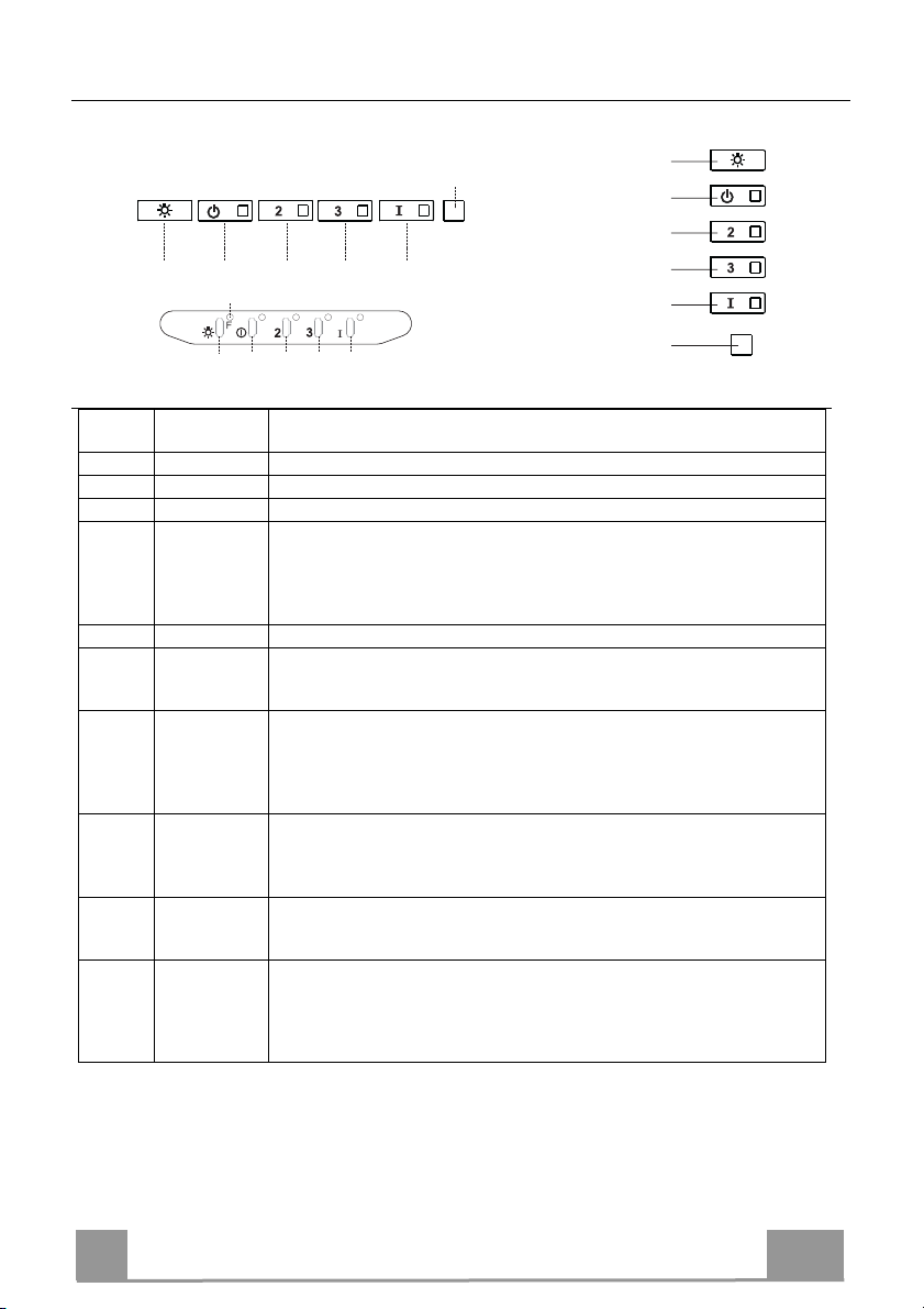
ΧΡΗΣΗ
S1
L
T1 T2 T3 T4
L
T1 T4
T3S1T2
Πίνακας χειριστηρίων
Πλήκτρο
Led Λειτουργία
L - Ανάβει/Σβήνει τα φώτα στη μέγιστη φωτεινότητα.
T1 Σταθερό Ανάβει/Σβήνει το μοτέρ στην πρώτη ταχύτητα.
T2 Σταθερό Ανάβει το μοτέρ στη δεύτερη ταχύτητα.
Κρατώντας το πλήκτρο πατημένο για περίπου 5 δευτερόλεπτα, όταν όλα τα φορ-
τία είναι σβηστά (μοτέρ+φώτα), ενεργοποιείται ο συναγερμός των φίλτρων ενεργού άνθρακα εμφανίζοντας μια διπλή αναλαμπή του αντίστοιχου Led.
Για την απενεργοποίηση, πιέστε και πάλι το πλήκτρο για άλλα 5 δευτερόλεπτα
εμφανίζοντας μια αναλαμπή του αντίστοιχου Led.
T3 Σταθερό Ανάβει το μοτέρ στην τρίτη ταχύτητα.
Κρατώντας το πλήκτρο πατημένο για περίπου 3 δευτερόλεπτα, όταν όλα τα φορ-
τία είναι σβηστά (μοτέρ+φώτα), επιτυγχάνεται ο μηδενισμός εμφανίζοντας μια
τριπλή αναλαμπή του Led S1.
T4 Σταθερό Ανάβει το μοτέρ στην ΕΝΤΟΝΗ ταχύτητα.
Η ταχύτητα αυτή ενεργοποιείται με χρονοδιακόπτη 6 λεπτών. Με την πάροδο
του χρόνου, το σύστημα επανέρχεται αυτόματα στην επιλεγμένη ταχύτητα. Αν
ενεργοποιηθεί με το μοτέρ σβηστό, με την πάροδο του παραπάνω χρόνου πηγαίνει στη λειτουργία OFF.
Κρατώντας πατημένο για 5 δευτερόλεπτα ενεργοποιείται το τηλεχειριστήριο
εμφανίζοντας μια διπλή αναλαμπή του ίδιου led.
Κρατώντας το πλήκτρο πατημένο για 5 δευτερόλεπτα απενεργοποιείται το τηλεχειριστήριο εμφανίζοντας την αναλαμπή του αντίστοιχου led μία μόνο φορά.
S1 Σταθερό Επισημαίνει το συναγερμό κορεσμού των μεταλλικών φίλτρων για λίπη και ότι
πρέπει να τα πλύνετε. Ο συναγερμός ενεργοποιείται μετά από 100 ώρες λειτουργίας του απορροφητήρα. (Μηδενισμός βλέπε παράγρ. Συντήρηση)
Αναβοσβήνει Επισημαίνει, όταν ανάψει, το συναγερμό κορεσμού του φίλτρου ενεργού άνθρα-
κα, που πρέπει να αντικατασταθεί. Πρέπει επίσης να πλύνετε και τα μεταλλικά
φίλτρα για λίπη. Ο συναγερμός κορεσμού του φίλτρου ενεργού άνθρακα ενεργοποιείται μετά από 200 ώρες λειτουργίας του απορροφητήρα. (Ενεργοποίηση και
Μηδενισμός βλέπε παράγρ. Συντήρηση)
L
T1
T2
T3
T4
S1
GR
55
5
Page 56

ΣΥΝΤΗΡΗΣΗ
ΤΗΛΕΧΕΙΡΙΣΤΉΡΙΟ (ΠΡΟΑΙΡΕΤΙΚΌ)
Η συσκευή ελέγχεται και με τηλεχειριστήριο που δέχεται αλκαλικές μπαταρίες ψευδαργύρου-άνθρακα 1,5 V στάνταρ τύπου
LR03-AAA (δεν περιλαμβάνεται).
• Μη βάζετε το τηλεχειριστήριο κοντά σε πηγές θερμότητας.
• Μην πετάτε τις μπαταρίες στο περιβάλλον, αλλά μόνο στους
ειδικούς κάδους.
Μεταλλικά φίλτρα για λίπη
Μπορούν να πλυθούν στο πλυντήριο πιάτων και απαιτούν πλύσιμο όταν ανάβει το Led S1 ή τουλάχιστον κάθε 2 μήνες χρήσης
ή συχνότερα σε περίπτωση ιδιαίτερα συχνής χρήσης.
ΚΑΘΑΡΙΣΜΟΣ ΦΙΛΤΡΩΝ
Μηδενισμός του συναγερμού
• Σβήστε τα φώτα και το μοτέρ αναρρόφησης.
• Πιέστε το πλήκτρο T3 για τουλάχιστον 3 δευτερόλεπτα, μέχρι
την τριπλή αναλαμπή επιβεβαίωσης
Καθαρισμός φίλτρων
• Βγάλτε το φίλτρο πιέζοντας προς το πίσω μέρος της συσκευής
και τραβώντας ταυτόχρονα προς τα κάτω.
• Πλύνετε το φίλτρο χωρίς να το στραβώσετε και αφήστε το να
στεγνώσει πριν το τοποθετήσετε στη θέση του (η ενδεχόμενη
αλλαγή χρώματος της επιφάνειας του φίλτρου με την πάροδο
χρόνου, δεν επηρεάζει με κανένα τρόπο την απόδοσή του).
του
• Τοποθετήστε το έτσι ώστε η λαβή να παραμείνει προς το εξωτερικό μέρος.
του Led.
GR
56
5
Page 57

Φίλτρα ενεργού άνθρακα για οσμές (Μοντέλο ανακύκλωσης)
Δεν μπορεί να πλυθεί και να αναγεννηθεί και πρέπει να αντικαθίσταται όταν αναβοσβήνει το
led S1 ή τουλάχιστον κάθε 4 μήνες. Η σήμανση συναγερμού, αν έχει προηγουμένως ενεργοποιηθεί, εμφανίζεται μόνον όταν λειτουργεί το μοτέρ αναρρόφησης.
Ενεργοποίηση του συναγερμού
• Στους απορροφητήρες μοντέλο ανακύκλωσης, η σήμανση του συναγερμού κορεσμού φίλτρων ενεργοποιείται κατά την εγκατάσταση ή στη συνέχεια.
• Σβήστε τα φώτα και το μοτέρ αναρρόφησης.
• Πιέστε για 5 δευτερόλεπτα το πλήκτρο T2 μέχρι τη διπλή αναλαμπή επιβεβαίωσης του
Led:
ΑΝΤΙΚΑΤΑΣΤΑΣΗ
Μηδενισμός του συναγερμού
• Σβήστε τα φώτα και το μοτέρ αναρρόφησης.
• Πιέστε το πλήκτρο T3 για τουλάχιστον 3 δευτερόλεπτα, μέχρι
την τριπλή αναλαμπή επιβεβαίωσης του
Αντικατάσταση φίλτρου
• Αφαιρέστε το φίλτρο για λίπη.
• Βγάλτε το κορεσμένο φίλτρο ενεργού άνθρακα αφού το ελευθερώσετε από τα στηρίγματα.
• Τοποθετήστε το νέο φίλτρο ενεργού άνθρακα στη θέση του.
• Τοποθετήστε το φίλτρο για λίπη.
Led.
GR
57
5
Page 58
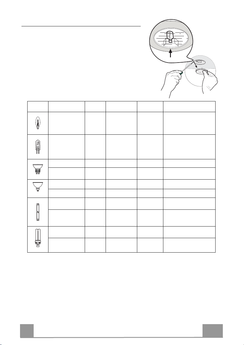
Φωτισμός
ΑΝΤΙΚΑΤΑΣΤΑΣΗ ΛΑΜΠΤΗΡΩΝ
Λαμπτήρες αλογόνου των 20 W.
• Βγάλτε τη μεταλλική πρεσαριστή ασφάλεια του
τζαμιού πιέζοντας κάτω από το δακτύλιο και
συγκρατώντας με το ένα χέρι.
• Βγάλτε το λαμπτήρα αλογόνου από το ντουί.
• Αντικαταστήστε τον με νέο λαμπτήρα ίδιων
χαρακτηριστικών, έτσι ώστε να προσαρμόσουν
σωστά τα δύο βύσματα στις υποδοχές του ντουί.
• Τοποθετήστε πρεσαριστά την ασφάλεια του τζαμιο
Λαμπτήρας Κατανάλωση (W) Κάλυκας Τάση (V) Διαστάσεις
(mm)
Κωδικός ILCOS
28 E14 220 – 240 104 x 35
20 G4 12 33 x 9 HSG/C/UB-20-12-G4
35 GU10 230 51 x 50,7 HAGS-35-230-GU10-51/40
50 GU10 230 51 x 50,7 HAGS-35-230-GU10-51/20
20 GU4 12 40 x 35 HRGS-20-12-GU4-35/30
20 GU5.3 12 46 x 51 HRGS-20-12-GU5.3-50/10
16 G13 95 720 x 26
18 G13 57 589,8 x 26
9 G23
11 G23
60 (λαμπτήρας)
220-240 (starter)
91 (λαμπτήρας)
220-240 (starter)
167 x 28 FSD-9/27/1B-I-G23
235,8 x 28 FSD-11/40/1B-I-G23
HSGSB/C/UB-28-220/240-E14
FD--16/40/1B-E--G13--26/720
FD--18/40/1B--E--G13--26/600
GR
58
5
Page 59

СОВЕТЫ И РЕКОМЕНДАЦИИ
В Инструкциях по эксплуатации описаны различные модели прибора.
Поэтому вы можете встретить описание некоторых характеристик, не
относящихся к приобретенному вами прибору.
УСТАНОВКА
• Изготовитель не несет ответственность за убытки, возникающие в результате
неправильной установки или эксплуатации прибора.
• Безопасное расстояние между варочной панелью и
всасывающей вытяжкой должно быть не менее 650
мм (некоторые модели можно устанавливать ниже; см.
раздел, посвященный рабочим размерам и операциям
по установке прибора).
• Проверьте соответствие напряжения сети указанному
на табличке, закрепленной внутри вытяжки.
• Для приборов класса I проверьте, чтобы в электрической сети вашего дома
была предусмотрена соответствующая система заземления.
Соедините вытяжку с дымоходом с помощью трубы минимального диаметра
120 мм. Труба для отведения дыма должна быть как можно короче.
• Не соединяйте всасывающую вытяжку с дымоходами, по которым выводится
дым, образующийся в процессе горения (например,
отопительные котлы, камины и проч.).
• Если вытяжной аппарат используется в сочетании с
приборами, работающими не от электрического тока
(например, газовые приборы), помещение должно
хорошо проветриваться во избежание обратного
потока отходящих газов. Для притока в помещение
свежего воздуха на кухне должно быть предусмотрено выходящее на улицу
окно. При пользовании кухонной вытяжкой в сочетании с приборами,
работающими не от электрического тока, отрицательное давление в
помещении не должно превышать 0,04 мбар с тем, чтобы дым не всасывался
вытяжкой обратно в помещение.
• Во избежание опасности в случае повреждения кабеля питания, он должен
быть заменен изготовителем или специалистами отдела технического
обслуживания.
2°
RU
59
5
Page 60

• Если в инструкциях по установке газовой плиты сказано, что расстояние до
вытяжки должно быть больше указанного выше, следует
придерживаться предписанных размеров. Соблюдайте все
нормативные требования по отведению отработанного воздуха.
• Используйте только винты и метизы, пригодные для установки
вытяжки. Предупреждение: использование винтов и зажимных
устройств, не соответствующих указаниям данных инструкций, может
привести к возникновению опасных ситуаций и к электрическим ударам.
• Соедините вытяжку с сетью питания с помощью двухполюсного
выключателя с минимальным разведением контактов 3 мм.
ЭКСПЛУАТАЦИЯ
• Всасывающая вытяжка предназначена только для применения в быту
для удаления из кухни запахов от готовки.
• Никогда не пользуйтесь вытяжкой в иных целях, отличных от тех, для
которых она предназначена.
• Никогда не оставляйте высокое пламя под вытяжкой, находящейся в
работе.
• Регулируйте силу пламени таким образом, чтобы оно оставалось под
дном емкости для готовки и не вырывалось за его пределы.
• При готовке во фритюрнице постоянно следите
за ее работой: сильно нагретое масло может
воспламениться.
• Не готовьте блюда фламбе под вытяжкой:
опасность возникновения пожара.
• Прибором могут пользоваться дети старше 8
лет и лица с ограниченными психическими, физическими и сенсорными
способностями, а также не имеющие достаточного опыта и знаний, но
только под присмотром ответственных лиц и при условии, что они
обучены безопасной эксплуатации прибора и знают о связанных с его
неправильным использованием опасностях. Следите, чтобы дети не
играли с прибором. Очистку и уход за прибором должен обеспечивать
пользователь, такие действия могут выполнять и дети, но только под
надзором взрослых.
RU
60
6
Page 61

• “ ВНИМАНИЕ: доступные части вытяжки могут сильно нагреваться во
время работы газовых приборов.
УХОД
• Перед выполнением любой операции по очистке и уходу выключите
или отсоедините прибор от электрической сети.
• Очищайте и/или заменяйте фильтры по истечении указанного периода
времени (опасность возникновения пожара).
• Жировые фильтры необходимо очищать раз в 2 месяца работы или
чаще в случае очень интенсивного использования прибора; жировые
фильтры можно мыть в посудомоечной машине.
• Фильтр на активированном угле нельзя мыть и восстанавливать, его
следует менять примерно раз в 4 месяца работы или чаще в случае
очень интенсивного использования прибора.
• "Опасность возникновения пожара, если очистка прибора не
выполняется в соответствии с инструкциями".
• Очищайте вытяжку влажной тряпкой, смоченной в нейтральном жидком
моющем веществе.
Символ на изделии или на упаковке указывает, что прибор нельзя
выбрасывать, как обычный бытовой мусор. Прибор, подлежащий
уничтожению, необходимо сдать в специальный сборный пункт для
повторного использования электрических и электронных компонентов.
Пользователь, правильно сдающий прибор на переработку, помогает
предотвратить потенциальные негативные последствия для окружающей
среды и для здоровья людей, возникающие в случае неправильного его
уничтожения. За более подробной информацией о вторичном
использовании прибора обращайтесь в городской совет, в местную
службу по переработке отходов или в магазин, где прибор был
приобретен.
RU
61
6
Page 62

ХАРАКТЕРИСТИКИ
Габариты
1000
545
598-698-798-898-1198
300
150
108
470 45
730
260
Части
Обозн.К-во Части изделия
1 1 Корпус вытяжки в комплекте с ручками управления,
освещением, вентилятором, фильтрами
2 1 Телескопическая дымовая труба, состоящая из:
2.1 1 Верхней дымовой трубы
2.2 1 Нижней дымовой трубы
9 1 Переходный фланец ø 150-120 мм
15 1 Выпускной патрубок воздуха
Обозн.К-во Установочные компоненты
7.2.1 2 Крепежные скобы верхней дымовой трубы
11 6 Вкладыши
12a 6 Винты 4,2 x 44,4
12c 6 Винты 2,9 x 9,5
К-во Документация
1 Руководство по эксплуатации
Min.
650mm
42
81
Min.
650mm
12b
64
RU
62
6
Page 63

УСТАНОВКА
Сверление стены и крепление скоб
7.2.1
1÷2
X
11
12a
116
116
305
650 min.
Провести на стене:
• вертикальную линию до потолка или до верхнего предела по центру участка, предусмотренного для установки вытяжки;
• горизонтальную линию на высоте мин. 650 мм от плиты.
Приложить, как показано на рисунке, скобу 7.2.1 к стене на расстоянии 1-2 мм от по-
толка или от верхнего предела
, выровняв ее центр (прорези) по исходной вертикаль-
ной линии.
• Обозначить центры отверстий скобы.
• Приложить, как показано на рисунке, скобу 7.2.1 к стене на расстоянии Х мм под пер-
вой скобой (Х = высота верхней части дымохода, прилагаемого в комплекте), выровнять ее центр (прорези) по исходной вертикальной линии.
• Обозначить центры
отверстий скобы.
• Сделать, как показано, отметку на расстоянии 116 мм от исходной вертикальной линии и 305 мм над исходной горизонтальной линией.
• Повторить эту операцию с противоположенной стороны.
• В обозначенным точках просверлить отверстия Ø 8 мм.
• Вставить в отверстия вкладыши 11.
• Закрепить скобы комплектующими винтами 12a ( 4,2 x 44,4).
• Ввинтить 2 прилагаемых винта 12a (4,2 x 44,4) в
отверстия крепления корпуса вытяж-
ки, оставив расстояние 5-6 мм между стеной и головкой винта.
RU
63
6
Page 64

Установка корпуса вытяжки
12a
Vr
9
ø 120ø 150
• Прежде чем повесить корпус вытяжки, затянуть 2 винта
Vr, расположенные в точках навески вытяжки.
• Повесить корпус вытяжки на предназначенные винты 12a.
• Затянуть до конца опорные винты 12a.
• Винтами Vr выровнять корпус вытяжки
Соединения
ВЫПУСК ВОЗДУХА ИЗ ВСАСЫВАЮЩЕЙ ВЫТЯЖКИ
Для установки всасывающей вытяжки соединить ее с выпускной трубой жесткой или гибкой трубкой диаметром 150
или 120 мм, тип которой может выбрать монтажник.
• Для соединения трубкой Ø 120 мм вставить переходный фланец 9 в
выпускное отверстие корпуса вытяжки.
• Закрепить трубку соответствующими трубными зажимами. Необходимый крепежный материал не
плект.
• Вынуть фильтры от запахов на активном угле.
входит в ком-
ВЫПУСК ВОЗДУХА В РЕЖИМЕ ФИЛЬТРАЦИИ
• Развинтите 2 винта крепления верхней скобы 7.2.1.
• На ее место привинтите выпускной патрубок воздуха 15 с
помощью 2 снятых винтов.
• Соедините патрубок 15 с выпускным отверстием в корпусе
вытяжки жесткой или гибкой трубкой (по усмотрению
монтажника) диаметром 150 мм.
• Проверьте наличие фильтра против запахов на
активированном угле
.
RU
6
64
Page 65

ЭЛЕКТРИЧЕСКОЕ ПОДКЛЮЧЕНИЕ
• Соединить вытяжку с сетевым напряжением, установив
двухполюсный выключатель с разведением контактов не
менее 3 мм.
• Снять противожировые фильтры (смотри раздел “Уход”)
и проверить правильность положения разъема питающего
кабеля в розетке вытяжки
Установка дымохода
Верхний дымоход
• Слегка развести две боковые кромки дымохода, зацепить
их за скобы 7.2.1 и вновь свести до упора.
• Закрепить дымоход сбоку 4 входящими в комплект винтами 12c (2,9 x 9,5).
• Проверить, чтобы выпускное отверстие насадок патрубка
совпало с решетками дымохода.
Нижний дымоход
• Слегка развести две боковые кромки дымохода, зацепить
их между
упора.
• Закрепить нижнюю часть дымохода сбоку к корпусу вытяжки входящими в комплект 2 винтами 12c (2,9 x 9,5).
верхним дымоходом и стеной и вновь свести до
12b
RU
65
6
Page 66

ЭКСПЛУАТАЦИЯ
S1
L
T1 T2 T3 T4
L
T1 T4
T3S1T2
Панель управления
Кнопка Индикатор Функция
L - Включает и выключает освещение максимальной интенсивности..
T1 Ровный свет Включает и выключает двигатель на первой скорости.
T2 Ровный свет Включает двигатель на второй скорости.
При нажатии кнопки в течение примерно 5 секунд, когда все нагрузки вы-
ключены (двигатель + освещение), включается аварийный сигнал фильтров
на активированном угле и два раза мигает соответствующий индикатор.
Чтобы отключить сигнализацию, еще раз нажмите кнопку в течение 5 секунд, пока соответствующий индикатор на вспыхнет один раз.
T3 Ровный свет Включает двигатель на третьей скорости.
При нажатии кнопки в течение примерно 3 секунд, когда все нагрузки вы-
ключены (двигатель + освещение), производится сброс команды и три раза
мигает индикатор S1.
T4 Ровный свет Включает двигатель на ИНТЕНСИВНОЙ скорости.
Такая скорость ограничена таймером на 6 минут. По истечении этого времени система автоматически возвращается к работе на выбранной ранее скорости. Если же скорость настроена при отключенном двигателе, по истечении
указанного времени система приходит в режим ВЫКЛ.
Нажатием кнопки в течение 5 секунд включается пульт ДУ, о чем свиде-
тельствуют две вспышки этого же индикатора.
Нажатием кнопки в течение 5 секунд пульт ДУ отключается, о чем свидетельствует одна вспышка соответствующего индикатора.
S1 Ровный свет Обозначает аварийный сигнал насыщения металлических жировых фильт-
ров и необходимость их помыть. Сигнал включается после 100 часов фактической работы вытяжки. (Сброс сигнала см. в разделе Обслуживание)
Мигающий свет Указывает на насыщение фильтра против запахов на активированном угле,
который должен быть заменен; при этом должны быть также помыты металлические жировые фильтры. Аварийный сигнал насыщения фильтров
против запахов на активированном угле срабатывает после 200 часов фактической работы вытяжки. (Включение и сброс сигнала см. в разделе Обслуживание)
L
T1
T2
T3
T4
S1
RU
66
6
Page 67

УХОД
ПУЛЬТ ДИСТАНЦИОННОГО УПРАВЛЕНИЯ (ДОПОЛНИТЕЛЬНО)
Данным прибором можно управлять пультом дистанционного
управления на щелочных батарейках с угольным элементом 1,5 В
стандартного типа LR03-AAA (не включено в комплект поставки).
• Не оставлять пульт вблизи от источников тепла.
• Не выбрасывать батарейки вместе с обычным мусором,
складывать их в специальные сборные емкости.
Металлические жировые фильтры
Фильтры можно мыть в посудомоечной машине. Их следует
мыть, когда загорается индикатор S1 и не реже одного раза в
2 месяца работы, или даже чаще в случае особенно
интенсивного использования вытяжки.
ОЧИСТКА ФИЛЬТРОВ
Сброс аварийного сигнала
• Выключите освещение и двигатель всасывания.
• Нажмите кнопку T3 в течение не менее 3 секунд, пока
подтверждения два раза не вспыхнет индикатор.
Очистка фильтров
• Выньте фильтр; для этого прижмите его к задней стенке
вытяжки и одновременно надавите вниз.
• Осторожно, не погнув, помойте фильтр и просушите его
перед установкой (изменение цвета поверхности фильтра,
которое может возникнуть со временем, ни коим образом
не влияет на эффективность
• Поставьте фильтр на место так, чтобы ручка находилась с
видной наружной стороны.
его работы).
для
RU
67
6
Page 68

Фильтры против запахов на активированном угле (фильтрующая вытяжка)
Такой фильтр нельзя помыть или восстановить, его необходимо менять, когда мигает
индикатор S1, или не реже одного раза в 4 месяца. Если заранее активирована аварийная
сигнализация, она имеет место, только когда включается двигатель всасывания.
Включение аварийного сигнала
• В вытяжках с функцией фильтрации аварийный сигнал насыщения фильтров должен
быть активирован в момент
• Выключите освещение и двигатель всасывания.
• В течение 5 секунд нажмите кнопку T2, чтобы в качестве подтверждения два раз
мигнул индикатор:
ЗАМЕНА
Сброс сигнала тревоги
• Выключите освещение и двигатель всасывания.
• Нажмите кнопку T3 в течение не менее 3 секунд, пока для под-
тверждения три раза не вспыхнет
Замена фильтра
• Выньте жировой фильтр.
• Выньте насыщенный фильтр против запахов на активированном
угле, отсоединив специальные защелки.
• Установите в соответствующее положение новый фильтр.
• Установите масляный фильтр.
установки прибора или позднее.
индикатор.
RU
68
6
Page 69

Освещение
ЗАМЕНА ЛАМП
Галогенные лампы 20 Вт.
• Надавить на металлическое зажимное кольцо и
вынуть, поддерживая, крышку лампы.
• Вынуть галогенную лампу из патрона.
• Заменить ее на новую с такими же характери-
стиками; правильно вставить два штыревых
контакта в гнездо лампового патрона.
• Надавив, поставить на место крышку лампы.
Лампа Потребление (Вт) Патрон Напряжение (В) Размер (MM) Код ILCOS
28 E14 220 – 240 104 x 35
20 G4 12 33 x 9 HSG/C/UB-20-12-G4
35 GU10 230 51 x 50,7 HAGS-35-230-GU10-51/40
50 GU10 230 51 x 50,7 HAGS-35-230-GU10-51/20
20 GU4 12 40 x 35 HRGS-20-12-GU4-35/30
20 GU5.3 12 46 x 51 HRGS-20-12-GU5.3-50/10
16 G13 95 720 x 26
18 G13 57 589,8 x 26
9 G23
11 G23
60 (лампа)
220-240
(пускатель)
91 (лампа)
220-240
(пускатель)
167 x 28 FSD-9/27/1B-I-G23
235,8 x 28 FSD-11/40/1B-I-G23
HSGSB/C/UB-28-220/240-E14
FD--16/40/1B-E--G13--26/720
FD--18/40/1B--E--G13--26/600
RU
69
6
Page 70

TAVSIYELER VE ÖNERILER
Kullanım talimatları, bu ev aletinin çeşitli modelleri için geçerlidir. Aynı
şekilde, bu ürünle ilgisi olmayan özelliklerin tanımlarını da görebilirsiniz.
MONTAJ
• Yanlış veya hatalı montajdan doğan yaralanma ve hasarlar için imalatçı
yükümlü olmayacaktır.
• Pişiricinin üst kısmı ve davlumbaz arasındaki
minimum güvenlik mesafesi 650 mm'dir. (Bazı
modeller daha alçak mesafeye monte edilebilir,
lütfen çalışma boyutları ve montaj paragraflarına
bakınız.)
• Ana voltajın davlumbazın iç tarafına sabitlenmiş
olan derecelendirme plakasındaki ile uyumlu
olduğunu kontrol edin.
• I. sınıf ev aletleri için, ev güç kaynağının yeterli
topraklama sağladığından emin olun.
Aspiratörü egzoz bacasına minimum çapı 120 mm olan bir boru vasıtasıyla
bağlayın. Baca hattı mümkün olduğu kadar kısa olmalıdır.
• Davlumbazı tutuşabilir gazlar taşıyan egzoz kanallarına bağlamayın
(kazanlar, şömineler, vs.).
• Eğer davlumbaz elektrikli olmayan ev aletleri ile
birlikte kullanılacaksa (ör. gazlı ev aletleri), egzoz
gazının geri tepmesini engellemek adına odada
yeterli derecede bir havalandırma olması garanti
edilmelidir. Temiz havanın girişini garanti etmek
adına mutfakta temiz hava girişini sağlayan bir
açıklık olmalıdır. Davlumbazın elektrik dışında
enerji veren ev aletleri ile birlikte kullanılması
durumunda, davlumbazın gazları geri yollamasını engellemek adına odadaki
negatif basınç 0,04 barı aşmamalıdır.
• Güç kablosuna zarar gelmesi durumunda, herhangi bir riski engellemek
adına imalatçı veya teknik servis birimince değiştirilmelidir.
2°
TR
70
7
Page 71

• Gaz ocağının montaj talimatlarında yukarıda belirtilenden daha fazla bir
mesafe belirtilmişse, buna dikkat edilmesi gerekir. Hava deşarjı ile ilgili
yönetmeliklere uyulması gerekir.
• Davlumbazı desteklemek için sadece vida ve küçük parçalar kullanın.
Uyarı: İşbu talimatlar uyarınca vidaları veya sabitleme aletlerini
kullanmamak elektrik tehlikelerine yol açabilir.
• Davlumbazı, arasında en az 3mm irtibat mesafesi olan iki kutuplu bir anahtar
vasıtasıyla cereyana bağlayın.
KULLANIM
• Davlumbaz mutfak kokularını gidermek adına ev kullanımı için
tasarlanmıştır.
• Davlumbazı asla tasarlandığı amaçlar haricinde kullanmayın.
• Davlumbaz çalışırken altında boşuna yanan yüksek ateş asla bırakmayın.
• Ateş yoğunluğunu sadece tencere altında kalacak ve yanlardan
taşmadığından emin olacak şekilde ayarlayın.
• Fritözler kullanım esnasında sürekli izlenmelidir:
fazla ısınmış yağ, ateş alabilir.
• Davlumbaz altında flambe yapmayınız; yangın
riski.
• Bu ev aleti, 8 yaş üstü çocuklar ve fiziksel,
duyusal veya akli yetersizliği olan veya tecrübe ve
bilgi eksikliği olan kişilerce bu kişilerin güvenliğinden sorumlu olan kişilerin
gözetimi altında veya ev aletinin kullanımı ile ilgili talimatlar kendilerine
verildiği durumlarda kullanılabilir. Çocuklar, ev aleti ile oynamamalıdır.
Temizleme ve bakım gözetimde olmadıklarında çocuklarca yapılmayacaktır.
TR
71
7
Page 72

• “ DİKKAT: Pişirme aletleri ile kullanıldıklarında temas edilebilir parçalar
ısınabilir.”
BAKIM
• Herhangi bir bakım işlemine başlamadan evvel ev aletini kapatın veya ana
güç kaynağından fişini çekin.
• Belirlenmiş zaman sonunda filtreleri temizleyin ve/veya değiştirin (Yangın
tehlikesi).
• Yağ filtreleri her 2 ayda bir veya yoğun kullanım olması durumunda daha sık
olarak temizlenmelidir ve bulaşık makinesinde yıkanabilirler.
• Aktif karbon filtresi yıkanabilir değildir, yeniden kullanılamaz ve her 4 ayda
bir veya yoğun kullanım olması durumunda daha sık olarak değiştirilmelidir.
• "Temizliğin talimatlara uygun olarak yapılmadığı durumlarda yangın riski
vardır."
• Davlumbazı nemli bir bez ve nötr sıvı deterjanla temizleyin.
Ürün üstündeki veya paketindeki sembolü, bu ürünün evsel atık olarak
değerlendirilmeyeceğinin göstergesidir. Elektrikli ve elektronik ekipmanın geri
dönüşümü için uygun toplama noktasına teslim edilmelidir. Bu ürünün doğru
şekilde bertaraf edildiğinden emin olarak, bu atık ürününün uygun olmayan
şekilde işlenmesinden doğacak çevre ve insan sağlığı için potansiyel olumsuz
sonuçların engellenmesine yardımcı olacaksınız. Bu ürünün geri dönüşümü ile
ilgili daha detaylı bilgi için lütfen yerel yetkili ofisiniz, evsel atık bertaraf hizmeti
veya ürünü satın aldığınız mağaza ile irtibata geçiniz.
TR
72
7
Page 73

ÖZELLIKLER
Boyutlar
1000
545
598-698-798-898-1198
300
150
108
470 45
730
260
Parçalar
Ref. Adet Ürünün parçaları
1 1 Şunlardan oluşan davlumbaz gövdesi: Kumandalar,
Lamba, Fan grubu, Filtreler
2 1 Şunlardan oluşan teleskopik baca:
2.1 1 Üst baca
2.2 1 Alt baca
9 1 Redüksiyon Flanşı ø 150-120 mm
15 1 Hava Çıkışı Rakoru
Ref. Adet Montaj Parçaları
7.2.1 2 Üst Baca Tesbit Braketleri
11 6 Dübeller
12a 6 Vidalar 4,2 x 44,4
12c 6 Vidalar 2,9 x 9,5
Adet Belgeler
1 Talimat Kılavuzu
Min.
650mm
42
81
Min.
650mm
12b
64
TR
73
7
Page 74

MONTAJ
Kenarların Delinmesi ve Askıların Sabitlenmesi
7.2.1
1÷2
X
11
12a
650 min.
116
116
305
Duvar üzerinde çizin:
• Davlumbazın montajı için öngörülen bölgenin ortasında, tavan veya en uç yüksekliğe kadar
dikey bir çizgi;
• pişirme yüzeyinin en az 650 mm üzerinde yatay bir çizgi.
• Askı 7.2.1’i belirtilen şekilde, ortasını (çentik) referans dikey çizgiye hizalayarak, tavan
veya en uç yükseklikten 1-2 mm’ye dayayın.
• Askı deliklerinin ortalarını işaretleyin.
• Askı 7.2.1’i şekilde gösterildiği şekilde, ortasını (çentik) referans dikey çizgiye hizalayarak
ilk askının altına X mm’de dayandırın (X = donanımdaki Üst Baca yüksekliği).
• Askı deliklerinin ortalarını işaretleyin.
• Belirtildiği şekilde, referans dikey çizgiden 116 mm’de ve referans yatay çizgisinin 305 mm
üstüne bir referans noktası işaretleyin.
• Bu işlemi karşı
tarafta tekrarlayın.
• İşaretli noktaları ø 8 mm delin.
• 11 no.lu dübelleri deliklere yerleştirin.
• Askıları, donanımdaki 12a (4,2 x 44,4) vidalarını kullanarak sabitleyin.
• Davlumbaz gövdesinin sabitlenmesi için, duvar yüzeyi ile vida başı arasında 5-6 mm’lik bir
yer bırakarak, donanımdaki 2 adet 12a (4,2 x 44,4) vidayı takın.
TR
74
7
Page 75

Davlumbaz Gövdesi Montajı
9
ø 120ø 150
• Davlumbaz Gövdesini kancalara takmadadan önce gövde üzerindeki kancalama noktalarında bulunan 2 adet vidayı Vr sıkı-
nız.
• Davlumbaz Gövdesini vidalara 12a takınız.
• Destek vidalarını 12a nihai olarak sıkınız.
• Vr vidalarına müdahale ederek Davlumbaz Gövdesi seviyesini
hizalayınız.
Bağlantılar
ASPİRATÖRLÜ MODEL HAVA ÇIKIŞI
Aspiratörlü modelin montajı için, davlumbaz, montörün seçeceği
150 yada 120 mm çapında sert veya esnek bir boru ile çıkış kanalına bağlanmalıdır.
• ø120 mm çapında boru ile bağlantı için, redüksiyon flanşını (9)
davlumbaz gövdesi çıkışına yerleştiriniz.
• Boruyu uygun kelepçelerle sıkarak sabitleyiniz. Bu malzeme
davlumbaz donanımıyla birlikte verilmemiştir.
• Varsa aktif karbonlu koku alma filtrelerini çıkarınız.
Vr
12a
FİLTRELİ SİSTEMDE HAVA ÇIKIŞI
• Alt askıyı 7.2.1 sabitleyen iki vidayı yerinden sökünüz.
• Hava Çıkış Bağlantısını 15 daha önceden çıkarılmış olan 2
vida ile yerine sabitleyin.
• 15 no.lu Bağlantıyı, montaj görevlisinin seçimine göre ø150
mm çapında sert veya esnek bir hortum ile Davlumbaz
Gövdesi Çıkışına bağlayınız.
• Aktif Karbonlu Koku önleyici Filtrenin bulunduğundan emin
olunuz.
TR
7
75
Page 76

ELEKTRİK BAĞLANTISI
• Davlumbazı şebeke cereyanına bağlarken aray temas aralığı en
az 3 mm olan çift kutuplu bir elektrik anahtarı koyunuz.
• Yağ tutucu filtreleri çıkarınız (bakınız "Bakım" paragrafı) ve
besleme kablosu soketinin aspiratör prizine iyice takılmış olduğundan emin olunuz.
Bacanın montajı
Üst baca
• İki yan kenarı hafifçe açınız, bunları braketlerin 7.2.1 arkasına
geçiriniz ve tam dayanana kadar tekrar kapatınız.
• Cihaz donanımında verilen 4 adet vidayla 12c (2,9 x 9,5) yan
taraflarından braketlere sabitleyiniz.
• Rakor uzantılarının çıkışının baca ağızlarına denk gelmesine
dikkat ediniz.
Alt baca
• Bacanın iki yan kenarını hafifçe açınız, Üst baca ile duvar arasına geçirip tam dayanana kadar kapatınız.
• Cihaz donanımında verilen 2 adet vidayla 12c (2,9 x 9,5) alt
tarafını davlumbaz gövdesine sabitleyiniz.
12b
TR
76
7
Page 77

KULLANIM
S1
L
T1 T2 T3 T4
L
T1 T4
T3S1T2
Kumanda Tablosu
Tuş Led Fonksiyon
L
- Azami aydınlıkta ışıkları açar/kapar.
T1
Sabit Birinci hızda motoru çalıştırır/kapatır.
T2
Sabit İkinci hızda motoru çalıştırır.
Bütün elektrik akımları (Motor+Işık) kapalıyken yaklaşık 5 saniye boyunca tuşu basılı
tuttuğunuzda, çift “Led” ışığı yanarak "Karbon Filtresi" alarmı etkinleştirilir.
Devre dışı bırakmak için aynı tuşa yine 5 saniye boyunca tek “Led” ışığı yanana kadar basılı
tutulur.
T3
Sabit Üçüncü hızda motoru çalıştırır.
Bütün elektrik akımları (Motor+Işık) kapalıyken yaklaşık 3 saniye boyunca tuşu basılı
tuttuğunuzda S1 Led uçlu ışık yanarak tekrar başlatılır.
T4
Sabit Motoru YOĞUN hızda çalıştırır.
Bu hız 6 dakikaya ayarlanmıştır. Süre bittiğinde, sistem daha önceden ayarlanmış hıza otomatik
olarak tekrar döner. Eğer bu hız kapalı bir makineden ortaya çıkmışsa süre bittiğinde OFF
durumuna geçer.
5 saniye boyunca basılı tutarak “Led” ışığı iki kere yandığında telekumanda aktif hale gelir.
5 saniye boyunca basılı tutarak ilgili “Led” ışığı sadece bir kere yandığında telekumanda devre
dışı olur.
S1
Sabit Yağ Önleyici Metal Filtrelerinin dolduğunu ve yıkanmaları gerektiğini belirtmektedir. Alarm
Davlumbazın 100 saatlik yoğun kullanım süresinden sonra devreye girmektedir. (Bakım
bölümüne bakın)
Flaşör Koku Emici Aktif Karbonlu Filtrenin dolduğunu bildiren alarm, değiştirilmesi ve Yağ Önleyici
Metal Filtrenin de yıkanması gerektiğini belirtmektedir. Koku Emici Aktif Karbonlu Filtrenin
dolduğunu bildiren alarm, davlumbazın 200 saatlik yoğun çalışma saatinden sonra devreye
girmektedir. (Etkinleştirme için Bakım bölümüne bakınız)
L
T1
T2
T3
T4
S1
TR
77
7
Page 78

BAKIM
TELEKUMANDA (OPSİYONEL)
Bu cihaza bir telekumanda ile de komut verilebilir; bu kumanda
1,5 Voltluk çinko-karbonlu LR03-AAA tipi standart alkalin pillerle çalışır (dahil değildir).
• Telekumandayı ısı kaynakları yakınında bırakmaynız.
• Pilleri çevreye atmayınız, bunlara ayrılmış çöp toplama kaplarına atınız.
Yağ önleyici Metalik Filtreler
Bulaşık makinesinde yıkanabilirler. S1 ledi yandığında veya 2
ayda bir veya özellikle yoğun kullanımlarda daha sık aralıklarla
yıkanmaları gerekmektedir.
FİLTRELERİN TEMİZLENMESİ
Alarm sinyalinin sıfırlanması
• Işıkları ve aspiratör motorunu kapatın.
• En az 3 saniye boyunca T3 tuşuna Led uçlu ışığı yanana kadar
basılı tutun.
Filtrelerin Temizlenmesi
• Filtreyi grubun arka bölümüne doğru iterek ve aynı anda
aşağıya doğru çekerek çıkartın.
• Filtreyi bükmeden yıkayın ve yeniden takmadan evvel
kurumaya bırakın (zamanla Filtre yüzeyinde görülebilecek
olası bir renk değiş
• Tutamağın dış görünür tarafta olduğuna dikkat ederek filtreleri
tekrar monte edin.
ikliği, kesinlikle etkinliğine zarar vermez.)
TR
78
7
Page 79

Koku Önleyici Aktif Karbon Filtreler (Filtreli Sistem)
Yıkanamaz, geri dönüşümlü değildir, ekranda S1 ledi görüntülendiğinde veya en az 4 ayda bir
değiştirilir. Alarm sinyali, eğer önceden etkinleştirilmişse, sadece Aspirasyon Motoru çalıştırıldığı zaman çalışır.
Alarmın etkinleştirilmesi
• Filtre edici sürümlü Davlumbazlarda, Filtrelerin dolma alarmı sinyali, kurulum anında veya
devamında devreye alınır.
• Işıkları ve aspiratör motorunu kapatın.
• T2 tuşuna 5 saniye süreyle ledin onay ışığı iki kere yanana kadar basınız.
DEĞİŞTİRİLMESİ
Alarm sinyalinin sıfırlanması
• Işıkları
• En az 3 saniye boyunca T3 tuşuna Led uçlu ışığı yanana kadar
Filtrenin Değiştirilmesi
• Yağ önleyici filtreyi çıkarın
• Dolmuş olan Koku Emici Aktif Karbonlu Filtreyi ilgili
• Yeni Filtreyi yuvasına takarak monte edin.
• Yağ Filtresini çıkarın.
ve aspiratör motorunu kapatın.
basılı tutun.
kancalara müdahale ederek çıkartın.
TR
79
7
Page 80

Aydınlatma
AMPULLERİN DEĞİŞTİRİLMESİ
20 W haojen ampuller
• Metal cam klipsini halkanın altından destekleyerek
ve bir elinizle de tutarak sökünüz.
• Halojen ampulü duyundan çıkarınız.
• Aynı özelliğe sahip yenisiyle değiştiriniz ve iki adet
fişinin yuvasına iyi oturmasına dikkat ediniz.
• Cam tutucu klipsi bastırarak takınız.
Ampul Ampul Gücü (W) Duy/Soket Ampul Voltajı (V) Boyut (mm) ILCOS Kodu
28 E14 220 – 240 104 x 35
20 G4 12 33 x 9 HSG/C/UB-20-12-G4
35 GU10 230 51 x 50,7 HAGS-35-230-GU10-51/40
50 GU10 230 51 x 50,7 HAGS-35-230-GU10-51/20
20 GU4 12 40 x 35 HRGS-20-12-GU4-35/30
20 GU5.3 12 46 x 51 HRGS-20-12-GU5.3-50/10
16 G13 95 720 x 26
18 G13 57 589,8 x 26
9 G23
11 G23
60 (ampul)
220-240 (starter)
91 (ampul)
220-240 (starter)
167 x 28 FSD-9/27/1B-I-G23
235,8 x 28 FSD-11/40/1B-I-G23
HSGSB/C/UB-28-220/240-E14
FD--16/40/1B-E--G13--26/720
FD--18/40/1B--E--G13--26/600
TR
80
8
Page 81

PATARIMAI IR NUORODOS
Naudojimo instrukcijos taikomos keliems šio prietaiso variantams. Taigi
galite rasti aprašytas tokias savybes, kurios nebūdingos konkrečiam jūsų
prietaisui.
MONTAVIMAS
• Gamintojas nebus atsakingas už jokią žalą, atsiradusią netaisyklingai arba
netinkamai sumontavus prietaisą.
• Mažiausiasis saugus atstumas tarp viryklės
viršaus ir rinktuvo gaubto yra 650 mm (kai kurie
modeliai gali būti montuojami žemiau, žr.
paragrafus apie atstumus ir montavimą).
• Patikrinkite, ar tinklo įtampa atitinka įtampą,
nurodytą ant techninių duomenų lentelės,
esančios gaubto viduje.
• Patikrinkite, ar I klasės prietaisai yra tinkamai
įžeminti.
Rinktuvą prijunkite prie ventiliacijos kanalo, naudokite ne mažesnio kaip 120
mm skersmens vamzdį. Atstumas nuo garų rinktuvo iki ventiliacijos kanalo
turėtų būti kuo trumpesnis.
• Garų rinktuvo nejunkite prie dūmtakių, per kuriuos šalinami degimo metu
susidarę dūmai (boilerių, židinių ir t. t.).
• Jei rinktuvas yra naudojamas ne su elektros
įrenginiais (pvz., dujų degikliais), kambaryje turi
būti įrengta tinkama ventiliacija, kad išmetamosios
dujos nepatektų atgal į patalpą. Tarp virtuvės ir
lauko turi būti tiesioginė orlaidė, kad į patalpą
galėtų patekti gryno oro. Kai gartraukis yra
naudojamas su įrenginiais, kuriems reikalinga
kitokia energijos rūšis (ne elektra), neigiamas
slėgis patalpoje neturi viršyti 0,04 mbar – taip bus užtikrinta, kad gartraukis
nestums garų į patalpą.
• Jei pažeidžiamas elektros kabelis, jį turi pakeisti gamintojas arba techninės
priežiūros skyrius, kad būtų išvengta bet kokių pavojų.
2°
LT
81
8
Page 82

• Jei pagal dujų degiklio įrengimo instrukcijas nurodomas didesnis atstumas, į
tai turi būti atsižvelgta. Tai pat reikia laikytis nurodymų, kurie reguliuoja oro
išmetimą.
• Gartraukiui tvirtinti naudokite tik sraigtus ir mažas dalis.
Įspėjimas! Jei sraigtai ar tvirtinimo priemonės nebus montuojami pagal šias
instrukcijas, tai gali sukelti elektros saugumo pavojų.
• Prijunkite gaubtą į elektros tinklą, naudodami dvipolį jungiklį, tarpas tarp
kontaktų turi būti ne mažesnis nei 3 mm.
NAUDOJIMAS
• Garų rinktuvas buvo sukurtas naudoti tik namuose virtuvės kvapams šalinti.
• Rinktuvo niekada nenaudokite kitiems tikslams, kurie nenumatyti
instrukcijoje.
• Garų rinktuvui veikiant, po juo niekada nepalikite didelės atviros ugnies.
• Sureguliuokite liepsnos intensyvumą taip, kad liepsna būtų nukreipta į
keptuvės apačią, ji negali apimti šonų.
• Naudodami gilią keptuvę, turite būti atidūs:
perkaitęs aliejus gali užsiliepsnoti.
• Po garų surinktuvu negaminkite patiekalų, kuriuos
prieš patiekimą ant stalo užpila spiritu arba
konjaku ir uždega; yra gaisro pavojus.
• Šį prietaisą gali naudoti 8 metų ir vyresni vaikai
bei asmenys, turintys fizinių, jutiminių ar protinių gebėjimų sutrikimų, taip pat
asmenys, nemokėję ir nežinoję, kaip elgtis su prietaisu, jei tokie asmenys
yra prižiūrimi, buvo apmokyti, kaip saugiai su juo elgtis, ir supranta esamą
pavojų. Vaikams negalima žaisti su prietaisu. Vaikams valymo ir priežiūros
darbų atlikti be priežiūros negalima.
LT
82
8
Page 83

• ATSARGIAI! Jei viryklės naudojamos, rankomis paliečiamos dalys gali būti
karštos.
PRIEŽIŪRA
• Prieš atlikdami bet kokius priežiūros darbus, prietaisą išjunkite arba
ištraukite kištuką iš elektros tinklo.
• Po nurodyto laiko išvalykite ir (arba) pakeiskite filtrus (dėl gaisro pavojaus).
• Riebalų filtrai turi būti valomi kas 2 darbo mėnesius arba dažniau, jei viryklė
ir rinktuvas naudojami labai intensyviai; filtrus galima plauti indaplove.
• Aktyvuotos anglies filtras yra neplaunamas ir antrą kartą nenaudojamas, turi
būti pakeistas apytiksliai kas 4 darbo mėnesius arba dažniau, jei viryklė ir
garų surinktuvas naudojami intensyviai.
• Neatlikus numatyto valymo, gali kilti gaisro pavojus.
• Rinktuvą valykite drėgnu skudurėliu, naudodami neutralų skystą ploviklį.
Ant gaminio arba jo pakuotės esantis simbolis nurodo, kad šis prietaisas
nepriskiriamas prie įprastų buities atliekų. Prietaisas turi būti perduotas į
reikiamą surinkimo punktą, užsiimantį elektros ir elektroninės įrangos
perdirbimu. Tinkamai sunaikindami šį gaminį, aplinką ir žmogaus sveikatą
apsaugosite nuo galimų neigiamų pasekmių, kurių gali atsirasti dėl netinkamo
šio gaminio utilizavimo. Norėdami gauti daugiau informacijos apie šio gaminio
utilizavimą, kreipkitės į vietines miesto institucijas, savo buitinių atliekų
tvarkymo tarnybą arba parduotuvę, kurioje prietaisą nusipirkote.
LT
83
8
Page 84

PRIETAISO APRAŠYMAS
Kliūtis
1000
545
598-698-798-898-1198
300
150
108
470 45
730
260
Sudedamosios dalys
Nuor. Kiekis Gaminio sudedamosios dalys
1 1 Gaubto korpusas su: valdymo elementais, lempute,
pūstuvu, filtrais
2 1 Teleskopinis kaminas, susidedantis iš:
2.1 1 viršutinės sekcijos;
2.2 1 apatinės sekcijos.
9 1 150–120 mm ø redukcinė jungė
15 1 Oro išėjimo sujungimas
Nuor. Kiekis Montavimo sudedamosios dalys
7.2.1 2 Viršutinės kamino sekcijos fiksavimo laikikliai
11 6 Sienos kamščiai
12a 6 4,2 x 44,4 sraigtai
12c 6 2,9 x 9,5 sraigtai
Kiekis Dokumentacija
1 Instrukcijos vadovas
Min.
650mm
42
81
Min.
650mm
12b
64
LT
84
8
Page 85

MONTAVIMAS
Sienų gręžimas ir laikiklių tvirtinimas
1÷2
7.2.1
11
12a
116
116
X
305
650 min.
Sienos žymėjimas
• Ant atraminės sienos nubrėžkite vertikalią liniją iki lubų arba taip aukštai, kaip praktiškai
galite; brėžkite per vietos, kurioje gaubtas bus montuojamas, centrinę dalį.
• Nubrėžkite horizontalią liniją 650 mm virš viryklės. Laikiklį 7.2.1 tvirtinkite prie sienos
taip, kaip parodyta. Palikite apie 1–2 mm atstumą nuo lubų ar viršutinės ribos; centras
(išpjova) turi atitikti vertikalią orientacinę liniją.
• Sienoje pažymėkite skylių centrus laikikliuose.
• Laikiklį 7.2.1 tvirtinkite prie sienos taip, kaip parodyta, X mm žemiau pirmo laikiklio (X =
pateikiamos viršutinės kamino dalies aukštis); centras (išpjova) turi atitikti vertikalią liniją.
• Sienoje pažymėkite skylių centrus laikiklyje.
• Pažymėkite orientacinį tašką taip, kaip parodyta, 116 mm atstumą palikite nuo vertikalios
orientacinės linijos, 305 mm atstumą – virš horizontalios orientacinės linijos.
• Pakartokite šį veiksmą kitoje pusėje.
• Išgręžkite 8 mm skersmens skyles visų
• Į skyles įkiškite sienos kaiščius 11.
• Pritvirtinkite laikiklius, naudodami pateiktus sraigtus 12a (4,2 x 44,4).
• Du pateiktus sraigtus 12a (4,2 x 44,4) įkiškite į gaubto korpuso tvirtinimo skylutes,
palikdami 5–6 mm tarpą tarp sienos ir sraigto galvutės.
pažymėtų taškų centre.
LT
85
8
Page 86

Gartraukio korpuso montavimas
12a
Vr
9
ø 120ø 150
• Prieš užkabinant gartraukio korpusą prisukti 2 varžtus Vr kurie
randasi gartraukio korpuso prikabinimo vietoje.
• Užkabinti gartraukio korpusą ant varžtų 12a.
• Prisukti glutinai laikymo varžtus Vr kad susilygintų gartraukio
korpusas.
• Gartraukio korpuso balansavimui naudoti Vr varžtus.
Pajungimas
ORO IŠĖJIMAS TRAUKIMO BŪDU
Norint instaliuoti traukimo versiją pajunkite gartraukį prie
išeinamojo kietojo arba lankstaus 150 arba 120 mm diametro
vamzdžio pagal jūsų pasirinkimą.
• Norint prijungti su 120 mm diametro vamzdžiu įveskite
reduktorių 9 į dūmtraukio korpuso išeigą.
• Pritvirtinti vamzdį su specialiais prisukimo instrumentais. Šie
instrumentai nėra įtraukti į komplektą.
• Išimti kvapą sutraukiančius anglies filtrus.
ORO ANGA. RECIRKULIACINĖ VERSIJA
• Atsukite 2 sraigtus, laikančius viršutinį laikytuvą 7.2.1.
• Naudodami anksčiau atsuktus 2 sraigtus pritvirtinkite oro
angos jungiklį 15 į savo vietą.
• Prijunkite jungiklį 15 prie gartraukio kupolo naudodami ø150
mm standų arba lankstų vamzdį, jį pasirenka montavimo
darbus atliekantis technikas.
• Įsitikinkite, ar buvo įdėtas aktyvintosios anglies kvapo filtras.
LT
8
86
Page 87

PAJUNGIMAS PRIE ELEKTROS
• Pajungti gartraukį į tinklą panaudojant bipolinį jungiklį su
mažiausiai 3mm kontaktų atidarymu.
• Išimti riebalų sulaikymo filtrus (žiūreti par. Eksploatacija)
Dūmtakio surinkimas
Viršutinis traukiamasis dūmtakis
• Šiek tiek išplėskite dvi viršutinio dūmtakio puses ir užkabinkite
jas už laikiklių 7.2.1, įsitikinę, ar gerai užsifiksavo.
• Pritvirtinkite laikiklių šonus, naudodami pateikiamus 4 sraigtus
12c (2,9 x 9,5).
• Įsitikinkite, ar ilginamųjų dalių anga atitinka kamino angas.
Apatinis traukiamasis dūmtakis
• Šiek tiek išplėskite dvi dūmtakio puses, užkabinkite jas tarp
viršutinio dūmtakio ir sienos, įsitikinę, ar gerai užsifiksavo.
• Apatinę dalį šonu pritvirtinkite prie gartraukio korpuso, naudodami 2 pateikiamus sraigtus 12c (2,9 x 9,5).
12b
LT
87
8
Page 88

NAUDOJIMAS
S1
L
T1 T2 T3 T4
L
T1 T4
T3S1T2
Valdymo skydelis
Mygt
Šviesos
ukas
diodas
L
-
T1
Nustatytas Variklį įjungia / išjungia pirmu greičiu.
T2
Nustatytas Variklį įjungia antru greičiu.
Funkcija
Įjungia / išjungia apšvietimą maksimalia galia.
Paspauskite mygtuką ir laikykite nuspaudę apytiksliai 3 sekundes, kai visos apkrovos išjungtos
(variklis ir lemputės), kad įjungtumėte aktyvintos anglies filtro įspėjamąjį signalą. Atitinkamas
šviesos diodas tai patvirtina blykstelėdamas du kartus.
Norėdami išjungti įspėjamąjį signalą, vėl paspauskite mygtuką ir laikykite nuspaudę 3 sekundes.
Atitinkamas šviesos diodas blyksteli vieną kartą.
T3
Nustatytas Variklį įjungia trečiu greičiu.
Paspauskite mygtuką ir laikykite nuspaudę apytiksliai 3 sekundes, kai visos apkrovos išjungtos
(variklis ir lemputės), kad pakartotinai nustatytumėte filtro prisotinimo įspėjamąjį signalą.
Šviesos diodas S1 blyksteli tris kartus.
T4
Nustatytas Variklį įjungia INTENSYVIU greičiu.
Šiuo greičiu variklis dirbs 6 minutes. Pasibaigus šiam laikui, sistema automatiškai grįš prie
greičio, kuris buvo nustatytas anksčiau. Jei jis įjungiamas esant išjungtam varikliui, laiko
pabaigoje gartraukis persijungs į OFF (IŠJUNGTA) padėtį.
Paspauskite ir laikykite nuspaudę 3 sekundes, kad įjungtumėte distancinį valdymą, tai parodoma
šviesos diodui blykstelėjus du kartus.
Paspauskite ir laikykite nuspaudę 3 sekundes, kad išjungtumėte distancinį valdymą, tai
parodoma šviesos diodui blykstelėjus vieną kartą.
S1
Nustatytas Metalinio riebalų filtro prisotinimo signalas įspėja, kad būtina išplauti filtrą. Signalas yra
sužadinamas po 100 gartraukio darbo valandų. (Pakartotinis nustatymas, žr. paragrafą
„Priežiūra“)
Blykčiojantis Kai jis įjungtas, pradeda veikti aktyvintos anglies filtro prisotinimo signalas, įspėjantis, kad filtrą
reikia pakeisti; taip pat turi būti išplaunamas metalinis riebalų filtras. Aktyvintos anglies filtro
prisotinimo įspėjamasis signalas
įsijungia po 200 gartraukio darbo valandų. (Įjungimas ir pakartotinis nustatymas, žr. paragrafą
„Priežiūra“)
L
T1
T2
T3
T4
S1
LT
88
8
Page 89

VALYMAS IR PRIEŽIŪRA
VALDYMAS NUOTOLINIU PULTU (JEI YRA)
Prietaisą galima valdyti nuotoliniu pultu, kuriam reikia standartinių AAA tipo 1,5 V anglies cinko šarminių elementų (neįskaičiuotos).
• Nelaikykite valdymo pulto netoli šilumos šaltinių.
• Panaudotus elementus reikia išmesti į jiems skirtą vietą.
Metaliniai riebalų filtrai
Jie gali būti plaunami indaplove ir turi būti valomi, kai tik ekrane
pasirodo S1 šviesos diodas, arba bent kartą kas 2 naudojimo
mėnesius ar dažniau, jei gartraukis yra naudojamas ypač
intensyviai.
FILTRŲ VALYMAS
Pakartotinis įspėjamojo signalo nustatymas
• Išjunkite apšvietimą ir ištraukimo variklį.
• Paspauskite T3 ir laikykite nuspaudę bent 3 sekundes, kol
šviesos diodas tris kartus blykstelės, patvirtindamas veiksmą.
Filtrų valymas
• Išimkite filtrą, stumdami jį skyriaus galo link ir tuo pačiu metu
traukdami žemyn.
• Filtrą nuplaukite jo nelankstydami, palikite, kad gerai išdžiūtų
prieš jį vėl įdėdami (jei laikui bėgant filtro spalva pasikeičia,
tai visiškai neturės poveikio jo efektyvumui).
• Vėl įdėkite, atkreipdami dėmesį, ar rankenėlė nukreipta į priekį.
LT
89
8
Page 90

Aktyvintos anglies filtras (recirkuliacinė versija)
Filtro negalima plauti arba atnaujinti, jį reikia pakeisti, kai pradeda mirkčioti šviesos diodas
S1, arba kas 4 mėnesius. Įspėjamasis signalas, jei jis aktyvuotas, pasirodo tik tuomet, jei yra
įjungtas ištraukimo variklis.
Įspėjamojo signalo įjungimas
• Jei naudojamas recirkuliacinis gartraukis, apie filtro prisotinimą įspėjantis signalas turi būti
įjungtas jį įrengus arba praėjus šiek tiek laiko.
• Išjunkite apšvietimą ir ištraukimo variklį.
• Paspauskite mygtuką T2 ir laikykite nuspaudę 5 sekundes, kol šviesos diodas du kartus
blykstelės patvirtindamas veiksmą.
KEITIMAS
Pakartotinis įspėjamojo signalo nustatymas
• Išjunkite apšvietimą ir ištraukimo variklį.
• Paspauskite T3 ir laikykite nuspaudę bent 3 sekundes, kol
šviesos diodas tris kartus blykstelės, patvirtindamas veiksmą.
Filtro keitimas
• Išimkite metalinį riebalų filtrą.
• Naudodami pateiktus kabliukus, išimkite prisotintą aktyvintos
anglies filtrą.
• Įdėkite naują filtrą, jį užkabindami.
LT
90
9
Page 91

APŠVIETIMAS
Lemputės keitimas
20 W halogeninė lemputė.
• Nuimkite fiksuojamą lemputės dangtį, pakeldami jį iš
apačios nuo metalinio žiedo, viena ranka jį laikydami.
• Švelniai traukdami, išimkite halogeninę lemputę iš
jai skirto laikiklio.
• Pakeiskite lemputę nauja tokio paties tipo lempute,
įsitikinę, kad du kontaktai tinkamai įdėti į lempos
laikiklio korpusą.
• Uždėkite fiksuojamą lemputės dangtelį.
Lemputė Galingumas (W) Lizdas Įtampa (V) Matmenys (mm) ILCOS kodas
28
20 G4 12 33 x 9 HSG/C/UB-20-12-G4
35 GU10 230 51 x 50,7 HAGS-35-230-GU10-51/40
50 GU10 230 51 x 50,7 HAGS-35-230-GU10-51/20
20 GU4 12 40 x 35 HRGS-20-12-GU4-35/30
20 GU5.3 12 46 x 51 HRGS-20-12-GU5.3-50/10
16 G13 95 720 x 26
18 G13 57 589,8 x 26
9 G23
11 G23
E14
220–240
60 (lemputė)
220–240
(starteris)
91 (lemputė)
220–240
(starteris)
104 x 35 HSGSB/C/UB-28-220/240-E14
FD--16/40/1B-E--G13--26/720
FD--18/40/1B--E--G13--26/600
167 x 28
235,8 x 28 FSD-11/40/1B-I-G23
FSD-9/27/1B-I-G23
LT
91
9
Page 92
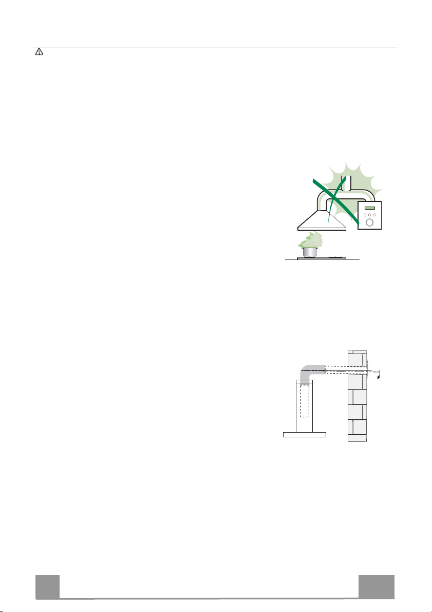
IETEIKUMI UN PRIEKŠLIKUMI
Lietošanas norādījumi attiecas uz vairākām šīs ierīces versijām. Tādējādi
iespējams, ka atradīsit atsevišķas funkcijas, kas nepiemīt konkrētajai
ierīcei.
UZSTĀDĪŠANA
• Izgatavotājs neuzņemas atbildību par bojājumiem, kas radušies nepareizas
uzstādīšanas rezultātā.
• Minimālais drošais attālums starp plīts virsmu un
tvaiku nosūcēju ir 650 mm (dažus modeļus var
uzstādīt zemāk, skatiet sadaļu par darba izmēriem
un uzstādīšanu).
• Pārbaudiet vai strāva mājas elektrotīklā atbilst
tehnisko datu plāksnītē norādītajā, kas
piestiprināta nosūcēja iekšpusē.
• 1. klases ierīces gadījumā pārbaudiet, vai mājas
elektrotīkls nodrošina pareizu zemējumu.
Pievienojiet nosūcēju izvades plūsmai ar cauruli 120 mm diametrā. Plūsmas
ceļam jābūt pēc iespējas īsākam.
• Nepievienojiet nosūcēju izplūdes cauruļvadiem, kas izvada sadegšanas
atlikuma produktus (boileri, kamīni utt.).
• Ja nosūcējs tiek izmantots kopā ar neelektriskām
ierīcēm (piem., gāzes plītīm), telpā jānodrošina
pietiekama ventilācija, lai nepieļautu izvadāmi
gāzu plūšanu atpakaļ. Virtuvei jābūt aprīkotai ar
atveri, pa kuru var ieplūst āra gaiss. Ja tvaika
nosūcējs uzstādīts savienojumā ar neelektriskā
ierīcēm, telpas negatīvais spiediens nedrīkst
pārsniegt 0,04 mbar, lai nepieļautu garaiņu
ieplūšanu atpakaļ telpā.
• Gadījumā, ja bojāts strāvas padeves kabelis, to jānomaina izgatavotāja vai
tehniskās apkalpošanas dienesta pārstāvim, lai nepieļautu nekādus riskus.
2°
LV
92
9
Page 93

• Ja gāzes plīts uzstādīšanas instrukcijās norādīts lielāks attālums, nekā
noteikts iepriekš, tad tas ir jāņem vērā. Jāizpilda noteikumi, kas saistīti ar
gaisa atbrīvošanu.
• Tvaika nosūcēja atbalstam izmantot tikai skrūves un mazās sastāvdaļas.
Brīdinājums: Ja skrūvju vai stiprinājuma ierīces uzstādīšanā nav ievērotas
šīs instrukcijas, tad var rasties elektriskās strāvas trieciena riski.
• Pievienojiet elektrotīklam ar divu polu slēdža palīdzību, kam saskares
atstarpe ir vismaz 3 mm.
IZMANTOŠANA
• Tvaika nosūcējs ir izstrādāts ekskluzīvi lietošanai mājsaimniecībā, lai
novērstu virtuves smakas.
• Nekad nelietot tvaika nosūcēju tādiem mērķiem, kādiem to nav paredzēts
lietot.
• Nekad zem funkcionējoša tvaika nosūcēja neatstāt lielas atklātas liesmas.
• Noregulēt liesmas intensitāti tikai tieši zem pannas, pārliecinoties, ka liesma
atrodas arī ārpus pannas malām.
• Dziļās tauku cepšanas ierīces lietošanas laikā ir
nepārtraukti jānovēro: pārkarsēta eļļa var liesmās
sadegt.
• Neuzstādīt zem tvaika nosūcēja gabarītiem;
aizdegšanās risks.
• Šo ierīci lietot drīkst 8 gadus veci un vecāki bērni,
kā arī personas ar ierobežotām fiziskām, sensoriskām vai garīgām spējām,
vai personas, kam nav pieredzes un zināšanu, ja tām ir nodrošināta
uzraudzība vai instrukcijas, kas saistītas ar drošu ierīces lietošanu un
ietverto bīstamības risku izpratni. Bērni nedrīkst spēlēties ar ierīci. Tīrīšanu
un ierīces kopšanu nedrīkst veikt bērni, ja tie netiek uzraudzīti.
LV
93
9
Page 94
• “ UZMANĪBU: Atklātās detaļas gatavošanas iekārtu izmantošanas laikā var
kļūt karstas.”
APKOPE
• Pirms jebkādu apkopes darbu veikšanas atslēdziet ierīci no elektrotīkla.
• Tīriet un/vai mainiet filtrus pēc noteikta laika perioda (aizdegšanās
briesmas).
• Tauku filtri jātīra ik pēc 2 darbības mēnešiem vai biežāk, ja ierīce tiek
intensīvi lietota, filtrus var mazgāt trauku mazgājamajā mašīnā.
• Aktīvās ogles filtrs nav mazgājams un nav atjaunojams, to jāmaina apmēram
pēc 4 mēnešu darbības vai biežāk, ja ierīce tiek izmantota intensīvi.
• Nespēja veikt tīrīšanu, kā norādīts var izraisīt ugunsbīstamību.
• Nosūcēju tīriet ar mitru lupatiņu un neitrālu šķidru mazgāšanas līdzekli.
Simbols uz izstrādājuma un tam pievienotajos dokumentos nozīmē, ka šo
ierīci nedrīkst izmest kopā ar parastiem sadzīves atkritumiem. Tā jānodod
elektrisko vai elektronisko preču savākšanas punktā, kur tos pieņem
pārstrādei. Nodrošinot šī izstrādājuma pareizu utilizāciju, Jūs palīdziet novērst
potenciāli negatīvu ietekmi uz vidi un cilvēku veselību, kas tomēr var notikt, ja
neievērosiet šī izstrādājuma utilizācijas noteikumus. Lai iegūtu
papildinformāciju par šī produkta pārstrādi, sazinieties ar savu pašvaldību,
vietējo atkritumu savākšanas dienestu vai veikalu, kurā iegādājāties šo
produktu.
LV
94
9
Page 95

TEHNISKIE DATI
Izmēri
1000
545
598-698-798-898-1198
300
150
108
470 45
730
260
Sastāvdaļas
Ats. Daudz. Izstrādājuma sastāvdaļas
1 1 Tvaiku nosūcēja korpuss, komplektā ar: vadības ele-
mentiem, apgaismojumu, ventilatoru, filtriem
2 1 Izbīdāmais dūmenis, kas sastāv no:
2.1 1 Augšējā daļa
2.2 1 Apakšējā daļa
9 1 Sašaurināšanas uzmava ø 150-120 mm
15 1 Gaisa izplūdes savienojums
Ats. Daudz. Uzstādīšanas sastāvdaļas
7.2.1 2 Augšējās dūmvada daļas fiksācijas skavas
11 6 Sienas tapas
12a 6 Skrūves 4,2 x 44,4
12c 6 Skrūves 2,9 x 9,5
Daudz. Dokumentācija
1 Lietošanas pamācība
Min.
650mm
42
81
Min.
650mm
12b
64
LV
95
9
Page 96

UZSTĀDĪŠANA
Sienu urbšana un kronšteinu nostiprināšana
1÷2
7.2.1
11
12a
116
116
X
305
650 min.
Atzīmes uz sienas:
• Novelciet vertikālu līniju uz balsta sienas līdz griestiem, vai, ja tas ir praktiskāk, tās vietas
centrā, pie kuras nosūcējs tiks uzstādīts.
• Novelciet horizontālu līniju 650 mm virs plīts virsmas. Pielieciet kronšteinu 7.2.1 pie sienas
kā parādīts apmēram 1-2 mm no griestiem vai augšējā ierobežojuma, salāgojot centru
(ierobi) ar vertikālo atsauces līniju.
• Atzīmējiet uz sienas skavas atveru centrus.
• Pielieciet kronšteinu 7.2.1 pie sienas kā parādīts par X mm zemāk par pirmo skavu (Х =
augšējas dūmvada daļas augstums, apvienojot centru (ierobi) ar vertikālo līniju.
• Atzīmējiet uz sienas skavas atveru centrus.
• Atzīmējiet atsauces punktu kā parādī
virs horizontālās atsauces līnijas.
• Atkārtojiet šo darbību otrā pusē.
• Izurbt ø 8 mm atveres atzīmētajos centra punktos.
• Ievietot atverēs sienas tapas 11.
• Nofiksēt kronšteinus, izmantojot komplektā ietvertās 12a skrūves (4,2 x 44,4).
• Ievietot divas komplektā ietvertās skrūves 12a (4,2 x 44,4) tvaika nosūcēja fiksācijas
atverēs, atstājot atstarpi 5-6 mm starp sienu un skrūves galviņu.
ts, 116 mm no vertikālās atsauces līnijas un 305 mm
LV
96
9
Page 97

Atsūcēja korpusa uzstādīšana
12a
Vr
9
ø 120ø 150
• Pirms pievienojat atsūcēja korpusu, pievelciet divas skrūves
Vr, kas atrodas korpusa montāžas punktos.
• Uzāķējiet korpusu uz skrūvēm 12a.
• Līdz galam pievelciet atbalsta skrūves 12a.
• Noregulējiet skrūves Vr līdz atsūcēja korpusa līmenim.
Savienojums
CAURUĻVADU VERSIJAS IZPLŪDES SISTĒMA
Uzstādot cauruļvada versiju, pievienojiet nosūcēju dūmvadam,
izmantojot elastīgu vai cietu cauruli ø 150 vai 120 mm, izvēli atstājiet uzstādītāja ziņā.
• Lai uzstādītu ø 120 mm gaisa izplūdes savienojumu, ievietojiet
samazinātāja uzmavu 9 tvaika nosūcēja korpusa izvadē.
• Fiksējiet cauruli ar atbilstošām caurules skavām (nav ietverti).
• Izņemt iespējamos aktivētās ogles filtrus.
GAISA IZEJA – RECIRKULĀCIJAS VERSIJA
• Atskrūvēt 2 skrūves, kas nostiprina augšējo kronšteinu 7.2.1.
• Nostiprināt savā vietā gaisa izejas savienotāju 15, izmantojot
iepriekš noskrūvētās 2 skrūves.
• Savienot savienotāju 15 ar tvaika nosūcēja pārsega izeju,
izmantojot stingru vai elastīgu cauruli ø150 mm, kuru izvēlas
uzstādīšanas speciālists.
• Pārliecināties, ka ir uzstādīts aktivizētās ogles smaku filtrs.
LV
9
97
Page 98

ELEKTRISKAIS SAVIENOJUMS
• Pievienojiet elektrotīklam ar divu polu slēdža palīdzību, kam
saskares atstarpe ir vismaz 3 mm.
• Izņemiet tauku filtrus (skatiet sadaļu „Apkope”), pārliecinoties,
ka padeves kabelis ir pareizi ievietots kontaktligzdā, kas atrodas ventilatora sānos.
Dūmvada montāža
Augšējais izplūdes dūmenis
• Nedaudz paplašiniet augšējā dūmvada abas puses un aizāķējiet
tās aiz skavām 7.2.1, pārliecinoties, ka tās labi piegulst.
• Nostipriniet sānus pie skavām ar 4 komplektā ietilpstošajām
skrūvēm 12c (2,9 x 9,5).
• Pārliecinieties, ka paplašinājuma detaļu izplūde ir horizontāli
un vertikāli salāgota ar dūmeņa izplūdēm.
Apakšējais izplūdes dūmenis
• Nedaudz paplašiniet dūmvada abas puses un pieāķējiet tā starp
augšējo dūmvadu un sienu, pārliecinoties, ka tās labi
piegulst.
• Fiksējiet apakšējo daļu šķē
2 komplektā ietilpstošās skrūves 12c (2,9 x 9,5).
rsām atsūcēja korpusam, izmantojot
12b
LV
98
9
Page 99

IZMANTOŠANA
L
T1 T2 T3 T4
L
T1 T4
Poga Signālla
L
T1
T2
T3
T4
S1
mpiņa
Fiksēts Ieslēgt/izslēgt motoru pirmajā ātrumā.
Fiksēts Ieslēgt motoru otrajā ātrumā.
Fiksēts Ieslēgt motoru trešajā ātrumā.
Fiksēts Ieslēgt motoru INTENSĪVAJĀ ātrumā.
Fiksēts Signalizē metāla tauku filtra piesātinājuma signalizācija, norādot, ka nepieciešams
Mirgoša
na
Funkcija
Iedegas ieslēgšanas/izslēgšanas signāllampiņas ar maksimālo intensitāti.
Nospiest un turēt nospiestu pogu apmēram 3 sekundes, izslēdzot visas slodzes
(motoru un apgaismojumu), lai ieslēgtu aktivētās ogles filtra signalizāciju.
Apstiprināšanai attiecīgas apgaismojuma lampiņas mirgo divreiz.
Lai izslēgtu signalizāciju, nospiest pogu vēlreiz un turēt nospiestu apmēram 3
sekundes. Attiecīgas apgaismojuma lampiņas mirgo vienreiz.
Nospiest un turēt nospiestu pogu apmēram uz 3 sekundēm, izslēdzot visas slodzes
(motors un signāllampiņas), lai veiktu filtra piesātinājuma signalizācijas
atiestatīšanu. Signāllampiņa S1 mirgo trīs reizes.
Šim ātrumam tiek uzstādīts 6 minūšu intervāls. Pēc tam sistēma automātiski
atgriezīsies iepriekš uzstādītajā ātrumā. Ja tas tiek aktivizēts kopā ar izslēgtu
motoru, tad tvaika nosūcējs laika perioda beigās tiek IZSLĒGTS.
Lai aktivizētu tālvadību, nospiest un turēt nospiestu 3 sekundes, ko norāda
signāllampiņas mirgošana divreiz.
Lai izslēgtu tālvadību, nospiest un turēt nospiestu 3 sekundes, ko norāda
signāllampiņas mirgošana vienreiz.
mazgāt filtrus. Signalizācija tiek aktivizēta, ja tvaika nosūcējs ticis ekspluatēts
100 darbības stundas. (Par atiestatīšanu, skatīt punktu Tehniskā apkalpošana)
Kad tā ir aktivizēta, tad signalizē aktivētās ogles filtra piesātinājuma signalizācija,
norādot, ka filtrs ir jānomaina; metāla tauku filtrs arī ir jāmazgā. Aktivētās ogles
filtra piesātinājuma signalizācija aktivizējas pēc tam, kad
tvaika nosūcējs darbojas 200 stundas. (Par atiestatīšanu, skatīt punktu Tehniskā
apkalpošana)
S1
T3S1T2
L
T1
T2
T3
T4
S1
Vadības panelis
LV
99
9
Page 100

APKOPE
TĀLVADĪBA (PAPILDAPRĪKOJUMS)
Ierīci var vadīt ar tālvadības pults palīdzību, ko darbina 1,5 V
oglekļa-cinka sārma baterijas standarta LR03-AAA tipa (nav ie-
tvertas komplektācijā).
• Nelieciet tālvadības pulti karstu virsmu tuvumā.
• Lietotās baterijas jāutilizē atbilstošā veidā.
Metāla tauku filtri
To var mazgāt trauku mazgājamā mašīnā, un to nepieciešams
tīrīt, ja displejā parādās signāllampiņas apzīmējums S1, vai
vismaz pēc katriem 2 lietošanas mēnešiem, vai biežāk, ja
lietošana ir īpaši intensīva.
FILTRU TĪRĪŠANA
Brīdinājuma signāla atiestatīšana
• Izslēgt apgaismojumu un sūkšanas motoru.
• Nospiest T3 pogu un turēt nospiestu vismaz 3 sekundes līdz tam,
kamēr apstiprināšanas signāllampiņas nenomirgos trīs reizes.
Filtru tīrīšana
• Izņemiet filtrus, spiežot tos virzienā uz grupas aizmuguri un vienlai-
cīgi velkot uz leju.
• Filtrus mazgāt, tos nesaliecot, un ļaut tiem pilnī
mainīšanas (ja laika gaitā filtram izmainās krāsa, tad tam nav nekā-
das ietekmes uz paša filtra efektivitāti).
• Nomainīt, nodrošinot, ka rokturis tiek vērsts uz priekšu.
bā izžūt pirms no-
LV
1
100
 Loading...