

Page 1
™
NII
N
UL 325 Non-compliant
R
R
R
R
effll
e
eccttiivv
e
e
e
P
P
h
h
ott
o
o
o
eyy
e
e
e
Operating Instructions
This product is an accessory or part of a system. Always read and follow the
manufacturer’s instructions for the equipment you are connecting this product to. Comply with
all applicable codes and safety regulations. Failure to do so may result in damage, injury or
death!
Page 2
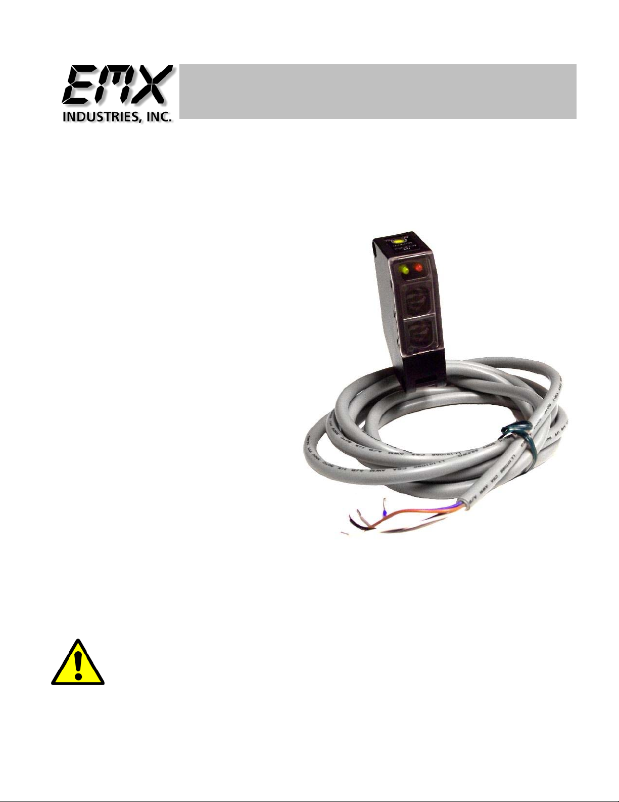
Product Overview
Product may be used for activation of gates or doors when the beam is interrupted. The NIR uses an Infrared
signal that is returned from a reflector mounted on the opposite side of the opening to be monitored.
WARNING … Not to be used for Personnel Protection
These sensors do NOT include the self-checking redundant circuitry
necessary to allow their use in personnel safety applications. A sensor failure or
malfunction can cause either an energized or de-energized sensor output
condition. UL 325 Non-compliant
Never use product as sensing devices for personnel
protection. Doing so could cause serious injury or death.
Technical Specifications
Power Supply 12 – 240 VDC 24 – 240 VAC
Power Supply Tolerance + / -10%
Current Draw 28mA standby 15mA detected @ 12 VDC
Housing Material
Relay Type SPDT 2A @ 24 VDC 0.6A @ 220VAC
Temperature Range -20 - +60C
Connector Cable 2 Meter (6 feet)
Environmental Protection IP 66 IEC
Size 1.6” x 2.6” x 0.8”
Response time 10ms maximum
Range 0.3 – 30 feet
Certifications CE
ABS and Acrylate on lenses
Controls, Indicators and Connections
Top
Sensitivity
Clockwise increases sensitivity
Normally set to maximum (single turn)
LED is on when unit is energized and signal is
stabile
Is on when is energized and alignment is correct
LED is off when unit is energized and object is
detected or not aligned
Yellow LED
Red LED
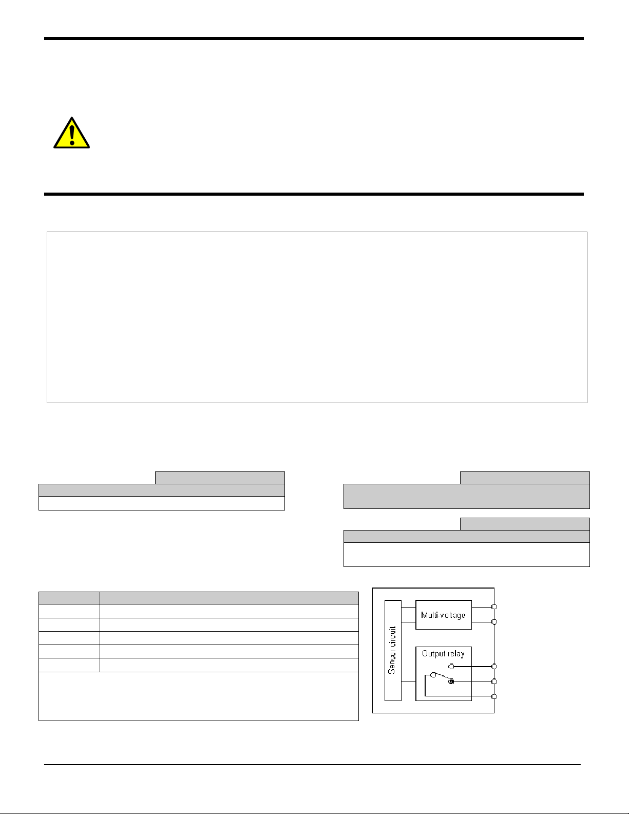
Wiring
Wire Color Connections
Brown Power Positive (+)
Blue Power Negative (-)
Black Internal Relay Contact Normally Closed (NC)
Gray Internal Relay Contact Normally Open (NO)
White Internal Relay Contact Common (COM)
Comments: The Blue wire and Brown wire are not polarity
sensitive. Unit is designed to operate on AC power
Brown (+)
Blue (-)
Black (NC)
Gray (NO)
White (COM)
Shown energized and aligned
NIR Instructions 2
Document no. NIR Instructions.doc REV 1.2 Date 11/16/2012
Page 3

Installation
Recommended alignment technique is to mount the NIR at the desired location and hold reflector about 2
or 3 feet in front of the unit and while watching the lights to assure that both remain lit, move backward
to the desired mounting location for the reflector. You may have to move the reflector up, down, left or
right to keep the reflector in the middle of the signal path. This assures the least troublesome set up by
keeping the reflector off the edges of the signal where any movement may take it out of alignment.
Note: the signal pattern is only 2 feet diameter.
Installer notes:
TROUBLE SHOOTING GUIDE
Symptoms Possible cause Possible Solution
Unit stays in detect Unit out of alignment
Reflector covered with dirt, dust, snow or
water
Water inside reflector
No Output No power
Bad Connection, wires broken
Mis-wired
No Detection Unit not powered
Other reflective surface causing signal return
Verify alignment
Clean reflector surface of
contaminants
Replace reflector
Add Reflector O-HD
Check Wiring as per chart on
page 2
Check connections
Verify wired to correct inputs
on operator
Check Power
Check surrounding area for
reflective surface
Ordering Information
NIR
Reflector-O
NIR-HD
Reflector-O-HD
Accessories
NIR-HD Reflector-O-HD Reflector-O
NIR Instructions 3
Document no. NIR Instructions.doc REV 1.2 Date 11/16/2012
Page 4

4564 Johnston Parkway
Cleveland, Ohio 44128
United States of America
WEB http://www.emxinc.com
E-mail salessupport@emxinc.com
Telephone (216) 518-9888
Fax (216) 518-9884
NIR Instructions 4
Document no. NIR Instructions.doc REV 1.2 Date 11/16/2012
 Loading...