

Page 1
EAD AND UNDERSTAND ALL INSTRUCTIONS BEFORE BEGINNING INSTALLATION.
R
The
M
iller
E
dge
M
odel
M
W
TA
12
t
ra
n
s
m
i
s
s
i
o
n
f
r
o
m
t
h
e
s
a
fe
t
y
e
d
g
e
T
h
e
M
o
d
e
l
M
WT
A
1
2
i
n
c
l
u
d
e
s
a
n
E
d
g
e
r
e
c
e
i
v
e
r
a
n
d
t
ra
n
s
m
i
t
t
e
r
h
a
v
S
e
l
e
c
t
a
b
l
e
fe
a
t
u
r
e
s
i
n
c
l
u
d
e
:
c
o
d
e
1-
Parts List
PART NUMBER
MWR12 Single Channel Receiver
MWT12 Single Channel Transmitter
MWTA12 Single Channel Transmitter with low
battery alarm
Kits:
MWRT12: includes MWR12, MWT12
MWRTA12: includes MWR12 and MWTA12
ALLATION INSTRUCTIONS
T
INS
Model # MWTA12, MWT12, MWR12, MWRT12, MWRTA12
IMPORTANT:
and
M
W
T12
saf
et
y
edge
t
r
ansm
it
t
er
s
ar
e
designed
t
o
t
h
e
m
o
t
o
r
c
o
n
t
r
o
l
s.
A
u
d
i
b
l
e
A
l
a
rm
fe
a
t
u
r
e
i
n
d
i
c
a
t
i
n
g
t
h
e
b
a
t
t
e
r
y
s
h
e
a
c
o
m
p
a
c
t
d
e
s
i
g
n
w
h
i
c
h
a
l
l
ow
s
fo
r
e
a
s
y
t
r
o
u
b
d
d
i
p
s
w
i
t
c
h
e
s
a
n
d
a
w
i
r
e
h
a
rn
e
s
s
fo
r
r
e
l
a
y
o
p
t
i
o
Tools Required:
1. 1/8” Flat blade screwdriver for wire connections
2. 1/4” Flat blade screwdriver for top lid screws
Recommended:
DVM for test purposes
(4) #6 - 20 x 3/4” self-drilling screws included,
Sensing edge (sold separately)
t
o
pr
o
vide
w
ir
el
ess
o
u
l
d
b
e
r
e
p
l
a
c
e
d
.
B
o
t
h
t
l
e
s
h
o
o
t
i
n
g
v
i
a
t
h
e
s
e
e
-
t
h
n
s.
h
e
r
signal
M
u
c
a
i
l
l
e
r
s
e.
2- Install Transmitter and Test
2-1. Open and unpack the batteries, Transmitter
and Receiver units.
2-2. Loosen Top Lid Screws on the Transmitter and remove lid.
Remove the Receiver Top Lid by pressing one side of the
snap lock base inward while lifting lid.
2-3. Set the 9 Pole, 3 Position Coding Switch on the Receiver to
match the Transmitter’s 9 Pole, 3 Position Coding Switch. Any
switch position will work as long as the Transmitter coding switch
and the Receiver coding switch are exactly matched (must be
different from other nearby transmitters of the same type).
2-4. Place the two (2) AA batteries in their holders on the Transmitter
in the proper direction, paying attention to the (+) and (-) ends.
Momentarily press the Test Button on the Transmitter.
The Green Tx LED Indicator should light for 3 seconds.
To test the Alarm on the MWTA12 Model, press and hold the
Test Button. The Alarm should sound in approximately ten (10)
seconds. Release the Test Button.
2-5. Route the wires from the safety edge through
the Transmitter’s Strain Relief Cable Fitting for
approximately four inches.
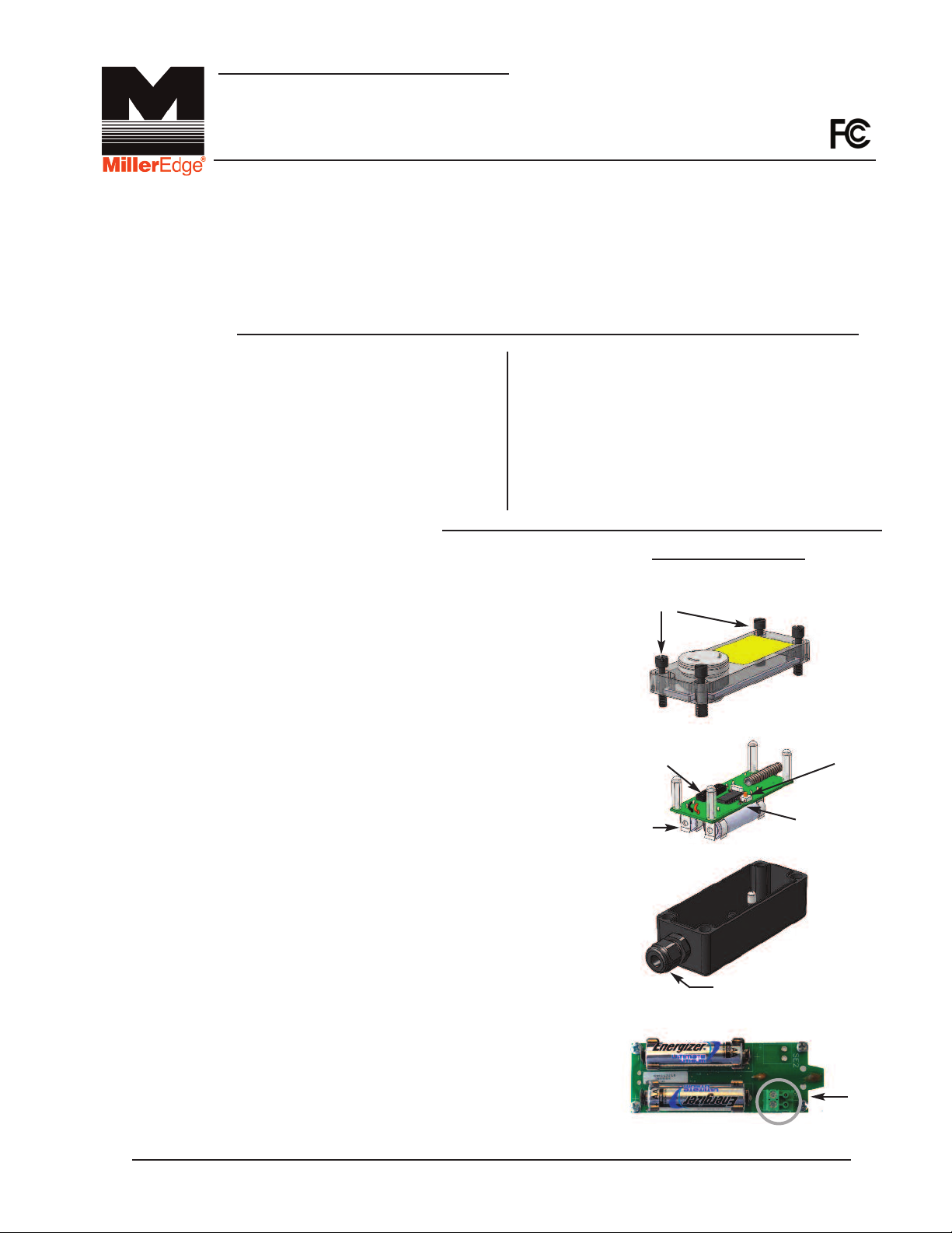
TRANSMITTER ENCLOSURE
Shown with Optional Alarm
TOP LID
SCREWS
9 POLE,
3 POSITION
CODING SWITCH
AA LITHIUM
BATTERIES
TEST BUTTON
GREEN TX
LED INDICATOR
2-6. Strip the insulation from the two wires back ¼”. Pull the
Terminal Block off the Transmitter’s PCB. Place the safety
edge wires in the Terminal Block and tighten with screwdriver.
Re-seat the Terminal Block on the PCB (see Fig. 2-6).
(-)
STRAIN RELIEF
CABLE FITTING
(+)
2-7. Re-seat the PCB into the Transmitter Enclosure and securely
tighten the Strain Relief Cable Fitting.
2-8. Now, compress your safety edge. The Green Tx LED Indicator
should light for about 3 seconds.
P.O. Box 159 • West Grove, PA 19390 • 800-220-3343 • 610-869-4422 • Fax: 610-869-4423 • www.milleredge.com
6809 South Harl Ave., Suite A • Tempe, AZ 85283 • 800-887-3343 • 480-755-3565 • Fax: 480-755-3558
(+)
Fig. 2-6 WIRE CONNECTION TO
TERMINAL BLOCK
(-)
TERMINAL
BLOCK
Safety Edge
Connection
MWTA12_Inst_20131007
Page 2
2- Install Transmitter and Test
2-9. The four (4) Pre-Drilled Corner Mounting Holes
re located on the far corners of the Transmitter
a
Enclosure. Mount the Transmitter to the gate
post, door end stile, or bottom angle using (4)
#6 - 20 x 3/4” self-drilling screws.
ount the transmitter with the wire outlet facing
M
down or to the side.
-10. Replace the cover on the Transmitter and
2
tighten the Top Lid Screws, taking care to align
the lid.
3- Install Receiver and Test
Cont.
4) PRE-DRILLED
(
ORNER
C
MOUNTING HOLES
3-1. Set the 9 Pole, 3 Position Coding Switch on the Receiver to
match the Transmitter’s 9 Pole, 3 Position Coding Switch. Any
switch position will work as long as the Transmitter coding switch
and the Receiver coding switch are exactly matched (must be
different from other nearby transmitters of the same type).
3-2. Mount Receiver inside the operator control box so that the wires
from the receiver will reach the terminal strip on the operator.
3-3. Wiring:
a. The red (+) and black (-) wires are your power leads. They
connect to your operator panel terminals that provide the
appropriate power (12-24 VAC/VDC). Black wire is common,
Red wire is (+) or AC power.
b. The green wire is your standard antenna wire. This must be
located outside of any metal enclosure to provide for good
signal reception. There is an F-Connector antenna fitting
included on the receiver in the event a remote antenna
placement is needed.
c. Receiver Connections: The white wire will go to your
operator’s low voltage common terminal. If your operator
requires a normally open (N.O.) contact, connect the
yellow wire to the operator’s safety edge input. If the
operator requires a normally closed (N.C.) contact,
connect the orange wire to the operator’s safety edge input.
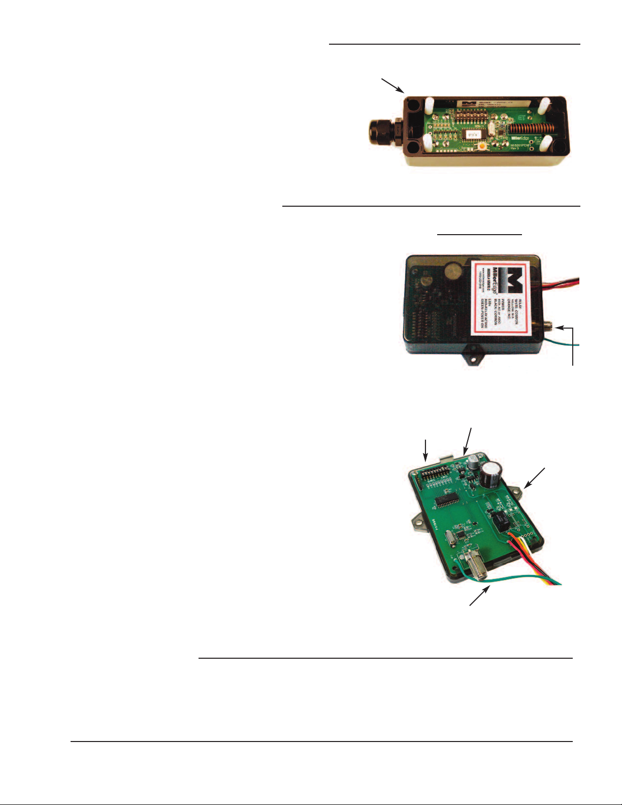
9 POLE,
3 POSITION
CODING
SWITCH
RECEIVER ENCLOSURE
F-CONNECTOR
ANTENNA
FITTING
LED
INDICATORS
MOUNTING
SCREW
HOLES
3-4. Preliminary Test:
Confirm that once power is applied to the Receiver, it’s green
LED is lit. Now press the Transmitter's test button and notice
that the red LED lights up on the Receiver and the green LED
lights up on the Transmitter.
3-5. Replace the Receiver Top Lid.
ANTENNA
4- Safety Test
4-1. While closing the door or gate, momentarily activate the safety edge and confirm that
the motor stops and reverses the door or gate direction.
P.O. Box 159 • West Grove, PA 19390 • 800-220-3343 • 610-869-4422 • Fax: 610-869-4423 • www.milleredge.com
6809 South Harl Ave., Suite A • Tempe, AZ 85283 • 800-887-3343 • 480-755-3565 • Fax: 480-755-3558
MWTA12_Inst_20131007
CH 1
Page 3

5- Specifications and Controls: Transmitter Unit
Code Switch: Selectable 9 pole, 3 position DIP
Frequency: 318 MHz.
Indicator Lights- Tx: Green LED: Tx Data
Mounting: (4) #6 self drilling screws included
Power Source: Batteries: 2 AA, 1.5v Alkaline or Lithium*
Recommended for extended life in prolonged cold environments. Life expectancy: 2 yrs.
*
Enclosure Rating: NEMA4
Modulation: On-Off Keying
Cable Connections: Screw clamp type terminal blocks for 14-26 awg wire.
Dimensions: MWT12: 5.75”w x 1.75”h x 1.8”d
MWTA12: 5.752”w x 2.125”h x 1.8”d
Antenna: Integral helical antenna.
Test Button: Momentary push button – Forces the transmission of the transmitter's address.
Low Battery: Model #MWTA12 only: 80-95dB Audible Alarm
Transmitted Signal Duration: Approx. 3 seconds
Response Time: Nominal 70 msec; Safety Edge Input to Receiver Relay Contact Output.
6-Specifications and Controls: Receiver Unit
Code Switch: Selectable 9 pole, 3 position DIP
Indicator Lights - Rx: Green LED: Power on; Red LED: Relay energized, indicates safety edge activation
Power Source: 10 to 40 VDC, 10-30 VAC (RMS)
Power Consumption: 16 mA (Idle) with Relay Off; 53 mA (avg.) with Relay On
Dimensions: 4.9”w x 3.75”h x 1.2”d
Cable Connections: Integral 18” wiring with #6 spade lugs.
Maximum Operating Distance: 100 Feet
7- FCC Compliance
Transmitter:
FCC ID: OYE-MWT120
THIS DEVICE COMPLIES WITH PART 15 OF THE FCC RULES. OPERATION IS SUBJECT TO THE FOLLOWING
TWO CONDITIONS.
1) THIS DEVICE MAY NOT CAUSE HARMFUL INTERFERENCE
AND
2) THIS DEVICE MUST ACCEPT ANY INTERFERENCE RECEIVED INCLUDING INTERFERENCE THAT MAY
CAUSE UNDESIRED OPERATION.
Receiver:
This equipment has been tested and found to comply with the limits for a Class B digital device, pursuant to Part 15 of the FCC Rules.
These limits are designed to provide reasonable protection against harmful interference in a residential installation. This equipment
generates, uses and can radiate radio frequency energy and, if not installed and used in accordance with the instructions, may cause
harmful interference to radio communications. However, there is no guarantee that interference will not occur in a particular installation. If this equipment does cause harmful interference to radio or television reception, which may be determined by turning the equipment off and on, the user is encouraged to try to correct the interference by one or more of the following measures:
1- Re-orient or relocate the receiver antenna
2- Increase the separation between the equipment and the receiver
3- Connect the equipment into an outlet on a circuit different from that to which the receiver is connected.
4- Consult the dealer or an experienced radio/TVtechnician for help.
Changes or Modifications Not Expressly Approved By The Party Responsible For Compliance Could Void The User’s
Authority To Operate The Equipment.
P.O. Box 159 • West Grove, PA 19390 • 800-220-3343 • 610-869-4422 • Fax: 610-869-4423 • www.milleredge.com
6809 South Harl Ave., Suite A • Tempe, AZ 85283 • 800-887-3343 • 480-755-3565 • Fax: 480-755-3558
MWTA12_Inst_20131007
 Loading...