

Page 1
READ AND UNDERSTAND ALL INSTRUCTIONS BEFORE BEGINNING INSTALLATION.
T
h
e
M
o
n
i
t
o
r
e
d
E
d
g
e
L
i
n
k
(
M
EL) t
ra
n
a
m
o
n
i
t
o
r
e
d
s
a
fe
t
y
e
d
g
e
a
n
d
a
m
o
t
o
U
L
-3
2
5
/2
0
1
0
r
e
q
u
i
r
e
m
e
n
t
s
fo
r
m
o
n
De
s
i
g
n
e
d
f
o
r
u
s
e
o
n
o
p
e
r
a
t
o
r
s
t
h
a
t
c
o
t
e
rm
i
n
a
t
i
o
n
o
p
t
i
o
n
s,
p
l
e
a
s
e
c
o
n
t
a
c
t
fa
1-
Parts List
PART NUMBER
Kit Contents:
1. MEL-TX20 Transmitter Unit
2. MEL-RX20 Receiver Unit
3. Receiver Antenna
4. (2) AA Lithium Batteries
5. 3 ft. 20 AWG lead wire
6. (4) #6 Pan Head Transmitter Mounting Screws
s
m
r
i
i
t
mp
c
ze
o
STR
N
I
N
O
TI
LLA
A
T
S
N
I
U
S
N
O
TI
C
Model # MEL-K20
MPORTANT:
I
i
t
t
e
r
/
r
e
c
e
i
v
e
r
s
y
s
t
e
m
i
s
i
n
t
e
n
d
e
d
t
o
p
r
o
v
i
d
e
a
w
i
r
e
l
e
s
s
c
o
n
n
e
c
t
i
o
n
b
e
t
w
e
e
n
d
o
p
e
ra
t
o
r
th
a
t
c
o
n
tro
ls
th
e
a
s
s
o
c
ia
te
d
d
o
o
r
o
r
g
a
te
.
M
E
L
m
e
e
ts
th
e
r
e
d
d
e
v
i
c
e
s
a
n
d
h
a
s
b
e
e
n
c
e
r
t
i
f
i
e
d
a
s
a
U
L
3
2
5
r
e
c
o
g
n
i
ze
d
c
o
m
p
o
n
e
n
t
.
l
y
wi
t
h
UL
3
2
5
-
2
0
1
0
u
s
i
n
g
a
T
2
o
r
T
3
t
e
r
mi
n
a
t
e
d
e
d
g
e
s
e
n
s
o
r.
F
o
r
a
d
d
i
t
i
o
n
a
l
t
o
r
y
.
Tools Required:
1. 1/8” Flat blade screwdriver
2. 1/4” Flat blade screwdriver
Recommended:
VOM for test purposes
Mounting screws as required
Terminated sensing edge sold separately
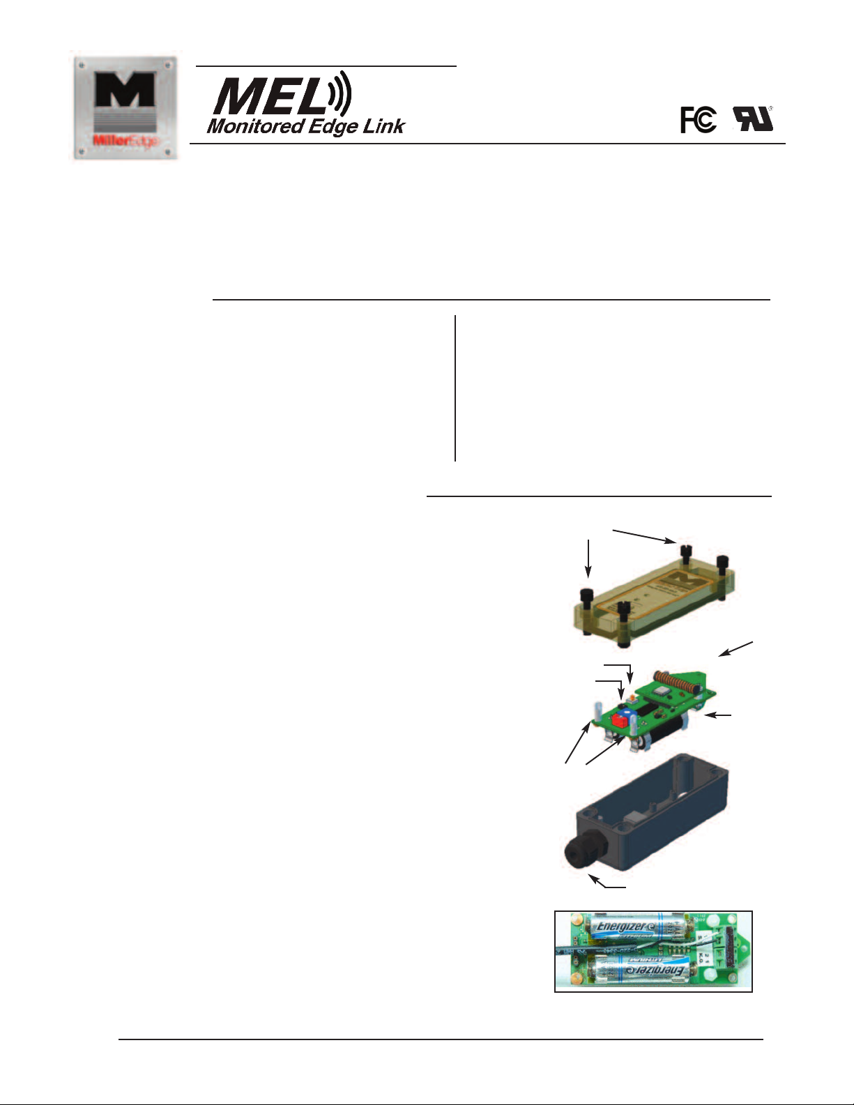
2- Install Transmitter and Test
2-1. Open and unpack the antenna, batteries, transmitter
and receiver units.
2-2. Loosen screws from the top cover and remove the lid.
2-3. Remove the Transmitter PCB by pulling upward on one
of the silicone caps.
2-4. Route the wires from the monitored edge through
the strain relief cable fitting for approximately four inches.
Strip the insulation from the two wires back ¼” and secure
the wires in the terminal strip position marked SE.
2-4A. A Knockout (K.O.) switch may be wired to the Tx
terminal strip marked KO-1 and KO-2. Either normally
open or normally closed switches may be used.
2-5. Place the two AA Lithium batteries in their holders in
the proper direction, paying attention to the (+) and (-) ends.
2-6. Tuck the wires connected to the SE terminal block neatly
between the batteries and pull the excess wire back
through the strain relief.
6-A. Re-seat the PCB and securely tighten the cable fitting.
2-7. Set the Termination Type switch to either 10K resistive
or 9.1v Diode. (see Appendix) This selection must match
the Termination type in the Monitored Device.
2-8. Address Switches
Set the Group(red) and Address (blue) switches to
the desired position. (Note the settings for reference when
setting up the Receiver)
If the Group switch is set to 0, the address switch may be
set to any position between 0 and F.
If the Group switch is set to 1, the Address switch may be
set to any position between 0 and B.
The remaining positions, C, D, E, and F are reserved for
factory test.
TOP LID
SCREWS
TEST BUTTON
2-POSITION
TERMINATION
SWITCH
SILICONE CAPS
2-6 WIRE CONNECTION TO
TRANSMITTER PCB
AA LITHIUM
BATTERIES
STRAIN RELIEF
CABLE FITTING
TERMINAL BLOCK
P.O. Box 159 • West Grove, PA 19390 • 800-220-3343 • 610-869-4422 • Fax: 610-869-4423 • www.milleredge.com
6809 South Harl Ave., Suite A • Tempe, AZ 85283 • 800-887-3343 • 480-755-3565 • Fax: 480-755-3558
MEL_Inst_20130201
Page 2
2-9. Momentarily press the TEST button to load the address and group data. The Green Tx Data led should flash.
The Red Low Battery led will only light when the batteries fall below 2.4v.
2-10. Mount the Transmitter to the door using #6 - 20 x 3/4” self-drilling screws.The mounting holes are located under
the Top Lid. Mount the transmitter with the wire outlet facing down or to the side.
-11. Replace the cover on the Transmitter and tighten the screws taking care to align the lid.
2
*Note the alignment pin located in the lower left corner.
(4) PRE-DRILLED
ORNER
C
OUNTING HOLES
M
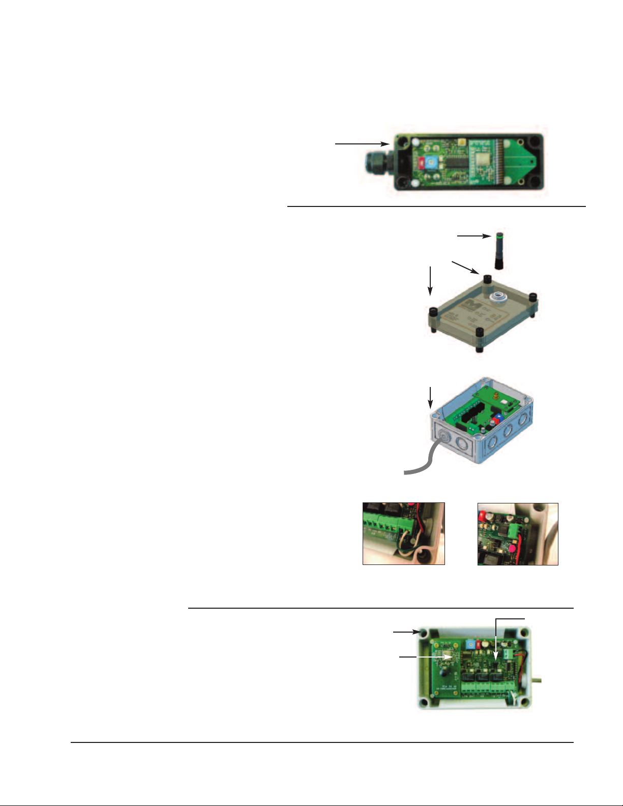
3- Install Receiver and Test
NTENNA
3-1. Loosen screws from the top lid of the Receiver Unit and
remove the lid.
3-2. Set the Group (red) and Address (blue) switches to
match the transmitter settings. (see Apendix)
3-3. Set the termination selection jumper to either 10k
resistive or 9.1v Diode (to suit the Operator).
3-4. Mount the receiver close to the operator and in the line
of sight of the transmitter using the pre-drilled mounting
holes as shown.
3-5. Connect the receiver’s PE (Photo Eye) output to the operator’s
photoeye input terminals using Green and White wires.
(operator terminal label naming may differ. Contact factory for
support). (See Pic.#1)
3-6. Connect 12/24V into 12/24VAC/DC source using Black and
Red wires. (See Pic. #2)
3-7. Connect the antenna to the receiver RF board.
3-8. Preliminary Test :
Confirm that the Transmitter and Receiver are powered ON.
Activate the Safety Edge (or monitored device).
The Address Valid Yellow led on the Receiver should
flashes momentarily.
IF the Address Valid led does not flash, check that the
Group and Address switches match the transmitter
settings. Confirm that the Photo-Eye and Safety Edge
leds are lit while the safety edge is held active.
Note that the Photo-eye and Safety Edge leds
go OFF when the Edge is released.
3-9. Replace the Receiver Lid taking
care to slip the Antenna
thru the top lid membrane.
3-5 Pic. #1
A
TOP LID
CREWS
S
TOP LID MOUNTING
SCREW HOLES
RECEIVER
TOP LID
RECEIVER
ENCLOSURE
3-6 Pic. #2
4- Safety Test
(4) PRE-DRILLED
4-1. While moving the door in the downward
direction, momentarily activate the safety
edge and confirm that the door stops and
reverses direction.
P.O. Box 159 • West Grove, PA 19390 • 800-220-3343 • 610-869-4422 • Fax: 610-869-4423 • www.milleredge.com
6809 South Harl Ave., Suite A • Tempe, AZ 85283 • 800-887-3343 • 480-755-3565 • Fax: 480-755-3558
CORNER
MOUNTING HOLES
LED
INDICATORS
INSIDE RECEIVER UNIT
TERMINATION
SELECTION
JUMPER
Page 3

5- Specifications and Controls: Transmitter Unit
Addressing Switches: Addressing codes allow for multiple transmitters to operate on the same frequency in close
proximity. See installation section of this manual.
Frequency: Multiple frequency modules available. Standard frequency: 315 MHz.303 MHz upon optional request.
ndicator Lights- Tx:
I
Green Led: Tx Data, Flashes upon activation and release of the external safety device to indicate
transmission.
Low Battery: Red Led. Flashes as a warning when the battery voltage is below 2.4v. All transmission ceases below 2.3v
Mounting: 4 corner screws Type as needed.
Power Source: Batteries: 2 AA, 1.5v Alkaline or Lithium*
Dimensions: 1.80” w x 4.78.” h x 1.75”d
*Recommended for extended life in prolonged cold environments. Life expectancy: 1 yr.
RF Module: Plug in module with integral helical antenna.
Termination Sw.: Selects termination type of the monitored device as 10K resistive or 9v diode-capacitor.
Test Button: Momentary push button – Forces the transmission of the transmitter's address and sensor status.
Loads an address change when the addressing switches are altered.
6-Specifications and Controls: Receiver Unit
Power: 12v-24v ac/dc nominal (8-30v max). Power may be supplied from the operator or alternately from an external supply.
Cable Entrance: Rubber seals for .15” - .2” diameter cables.
Cable Connections: Screw clamp type terminal blocks for 22 -24 awg wire.
Addressing: Group Switch: 2 position slide switch, selectable as “0” or “1”.
Address Switch: Selectable from 0 – 9 and A – F (See Address setting in the TX setup section.)
Dimensions: 3.70” w x 5.12.” h x 2.20”d
Indicator Lights - Rx:
Address Valid: Yellow Led
PE Alarm: Red Led: Indicates Photo-eye pulse stream loss
: Flashing indicates a termination error
SE Alarm: Green Led: Indicates Safety device activation
K.O. Switch Active: Green Led
Low Battery: Green Led–Flashing: Tx battery falls below 2.4v
Green Led–Steady: Tx battery falls below 2.3v
Outputs:
PE Output: Pulse stream output compatible with all UL-325/2010 listed commercial operators. (Check Operator Listing)
SE Output: SPDT relay contacts, NO, NC, and Com outputs. (See Termination Type)
The pulse stream stops and the relay activates when any of the following occurs:
1. Safety device activation
2. Open or unconnected safety device
3. Bad or missing safety device termination
4. Low Battery
5. Loss of radio signal or ping loss
Termination Type: 10K resistor or 9.1v Diode/Cap. Selectable by PCB Jumper/Header
KO Output: SPDT relay contacts, NO, NC, and Com outputs
Low Battery: SPDT relay contacts, NO, NC, and Com outputs
Alarm Power Switch: Provides either dry contacts or +5vdc @ 20 ma. Max on the relay contacts.
Position 0: Relay dry contacts
Position 1: 5v @ 20 ma supplied on relay NC
P.O. Box 159 • West Grove, PA 19390 • 800-220-3343 • 610-869-4422 • Fax: 610-869-4423 • www.milleredge.com
6809 South Harl Ave., Suite A • Tempe, AZ 85283 • 800-887-3343 • 480-755-3565 • Fax: 480-755-3558
Page 4

Alarm Power Switch: “LOW BAT” Provides for wiring of optional audible or visual alarm when battery life is
iminished. Optional dry contacts or +5vdc @ 20 ma. Max on the relay contacts.
d
Position 0: Relay dry contacts
Position 1: 5v @ 20 ma supplied on relay NC
7- Appendix:
Miller Edge Terminated Sensing Edge Color Coding:
Suggested Termination Configurations
T2 Blue 10K Resistor
T3 Red Diode/Capacitor
Optional Termination Configurations - Contact Factory
T1 Green 8.2K Resistor
T4 White .001 uf capacitor
T5 Orange 6.8K Resistor
T6 Violet 270K Resistor
* Colored ID tape is located on the Edge cable.
8- FCC Compliance
Transmitter:
MODEL: MEL-TX20
FCC ID: OYE-MDTR3
THIS DEVICE COMPLIES WITH PART 15 OF THE FCC RULES. OPERATIONS IS SUBJECT TO THE FOLLOWING
TWO CONDITIONS.
1) THIS DEVICE MAY NOT CAUSE HARMFUL INTERFERENCE
AND
2) THIS DEVICE MUST ACCEPT ANY INTERFERENCE RECEIVED INCLUDING INTERFERENCE THAT MAY
CAUSE UNDESIRED OPERATION.
This equipment has been tested and found to comply with the limits for a Class B digital device, pursuant to Part15 of the FCC Rules.
These limits are designed to provide reasonable protection against harmful interference in a residential installation. This equipment
generates, uses and can radiate radio frequency energy and, if not installed and used in accordance with the instructions, may cause
harmful interference to radio communications. However, there is no guarantee that interference will not occur in a particular installation. If this equipment does cause harmful interference to radio or television reception, which may be determined by turning the equipment off and on, the user is encouraged to try to correct the interference by one or more of the following measures:
1- Re-orient or relocate the receiver antenna
2- Increase the separation between the equipment and the receiver
3- Connect the equipment into an outlet on a circuit different from that to which the receiver is connected.
4- Consult the dealer or an experienced radio/TVtechnician for help.
Changes or Modifications Not Expressly Approved By The Party Responsible For Compliance Could Void The User’s
Authority TO Operate The Equipment.
400-MEL-001
MELBOOKLET_Inst_20130201
P.O. Box 159 • West Grove, PA 19390 • 800-220-3343 • 610-869-4422 • Fax: 610-869-4423 • www.milleredge.com
6809 South Harl Ave., Suite A • Tempe, AZ 85283 • 800-887-3343 • 480-755-3565 • Fax: 480-755-3558
 Loading...