

Page 1
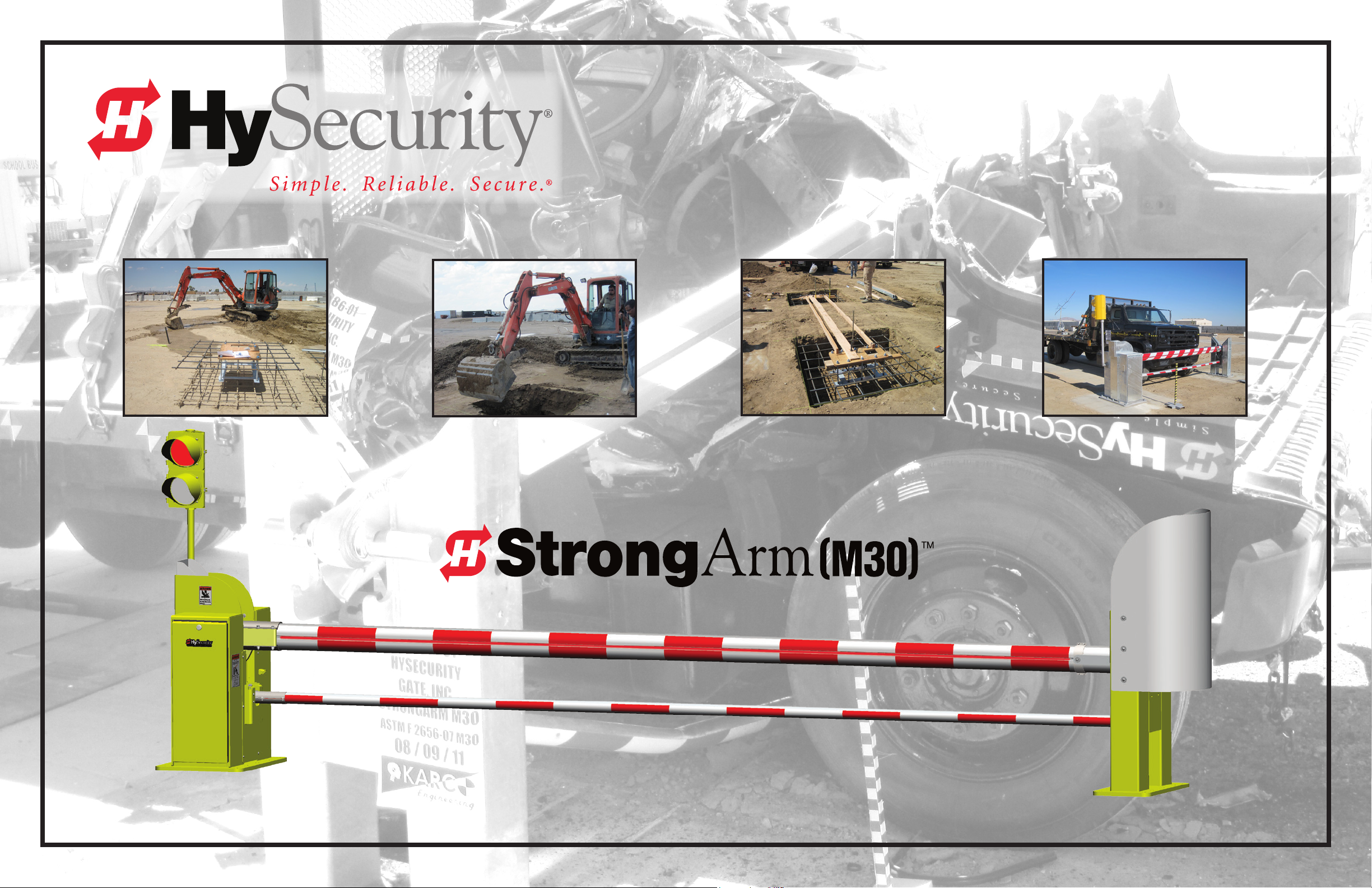
Installation Instructions
Patent Pending DO432
Page 2

Page 3
2
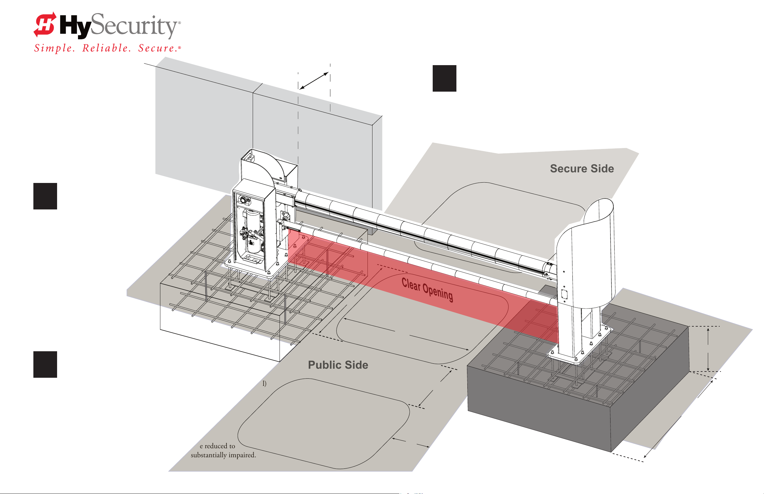
Measure the clear opening. Use the templates
provided to align conduit and determine placement
of the posts. Turn this page over to view Assemble and
Align and Mark instructions.
Minimum Clearance
for accessibility: 2 feet (61 cm)
M30 PLAN SITE DESIGN
Read & Plan
Read and follow the Important Safety Information provided in the Programming and Operations
1
Roadway
Manual prior to installing the StrongArm M30™ Crash Rated Fortied Barrier Arm. Review these
installation instructions and make sure to conform to site specications and all local and federal
regulations and codes.
Secure Side
Inside
Obstruction
Loop (IOLD)
Design Vehicle Loops
If automatic close is desired, a RESET and one other loop
3
Dimensions:
A = 6 to 16 feet (183 to 488 cm) B = 6 to 8 feet (183 to 244 cm)
C = Maintain 4 feet (122 cm) between loop & edge of roadway
D = Maximum distance is 5 feet (152 cm). Vehicle must move
from one loop to the next without loss of detection.
NOTE: If tailgating is a concern, dimension “B” may be reduced to
3 ft (91 cm), but detecting high bed vehicles will be substantially impaired.
(IOLD or OOLD) is required.
ree loops are preferred: RESET, IOLD, OOLD (Free Exit, optional)
B
Public Side
Outside
Obstruction
Loop (OOLD)
Clear Opening
Centered under Barrier Arm
Reset Loop
A
D
C
2 ft*
(61 cm)
6 ft*
(183 cm)
* Concrete Dimensions
6 x 6 x 2 foot (183 x 183 x 61 cm)
Optional: 4 x 4 x 4 foot square (122 x 122 x 122 cm)
© 2013 www.hysecurity.com
StrongArm M30 Installation & Assembly - Plan Site Design
D0432 Rev D
Page 1
Page 4

M30 ASSEMBLE & ALIGN & MARK
Roadway
C
/
L
24¼" (62 cm)
Use 2 x 6 (5.1 x 15.2 cm) board for alignment purposes.
Cut the board 2 (61cm) longer than Clear Opening.
C
/
L
Template Layout: 6 x 6 x 2 foot and 4 x 4 x 4 foot
Use Templates
To set the Pivot and Catch Posts in their respective locations, use the
16"
(41 cm)
1
C
/
L
anchor cage templates provided. Measure and cut one 2 x 6 (not provided)
exactly 2ft (61cm) longer than the Clear Opening and measure and cut
one 2 x 4 (not provided) equal to the Clear Opening. Secure both to the
anchor cage templates.
NOTE:
If standard lumber lengths are exceeded, two straight pieces may be
screwed together to reach the desired length.
36" (91 cm)
C
/
L
Pivot Post Template
72" (183 cm)
48" (122 cm)
25¾" to C.O.
(65 cm)
13¾" to C.O.
(35 cm) for 4 ft cage
Use a 2 x 4 (5.1 x 15.2 cm) cut to the same distance as
the Clear Opening.
CLEAR OPENING
Roadway
C
/
L
Catch Post Template
31⅝" to C.O.
(80 cm)
19⅝" to C.O.
(50 cm) for 4 ft cage
72" (183 cm)
48" (122 cm)
32" (81 cm)
C
/
L
IMPORTANT: Verify measurements.
Because of the nature of the StrongArm M30™, it is critical
to align the opening of the Catch Post with the center of the Pivot Post.
Measure and mark the excavation pit. Mark the
conduit openings and locate the conduit trenches
2
and rebar cages accordingly.
NOTE: e dashed square lines indicate excavation area
for concrete foundation.*
Sizes shown: 6 x 6 x 2 foot (183 x 183 x 61 cm)
Optional foundation size: 4 x 4 x 4 foot (122 x 122 x 122 cm)
(measurements shown in orange )
* Measurements based on centering templates on
concrete foundation.
REBAR CAGE: 6 x 6 x 2
Pivot & Catch post cages idencal.
Use #5 rebar, 5/8 in. (40 or beer).
66 inches (167 cm)
REBAR CAGE: 4 x 4 x 4
Pivot & Catch post cages idencal.
Use #5 rebar, 5/8 in. (60 or beer).
42 inches (107 cm)
72" (183 cm)
48" (122 cm)
66 in.
10 in.
10 in.
(25 cm)
O.C.
(25 cm)
O.C.
CLEAR OPENING
10 in.
O.C.
© 2013 www.hysecurity.com Page 2
StrongArm M30 Installation & Assembly - Assemble & Align Templates & Mark Openings D0432 Rev D
10.0
O.C.
42 in.
Page 5
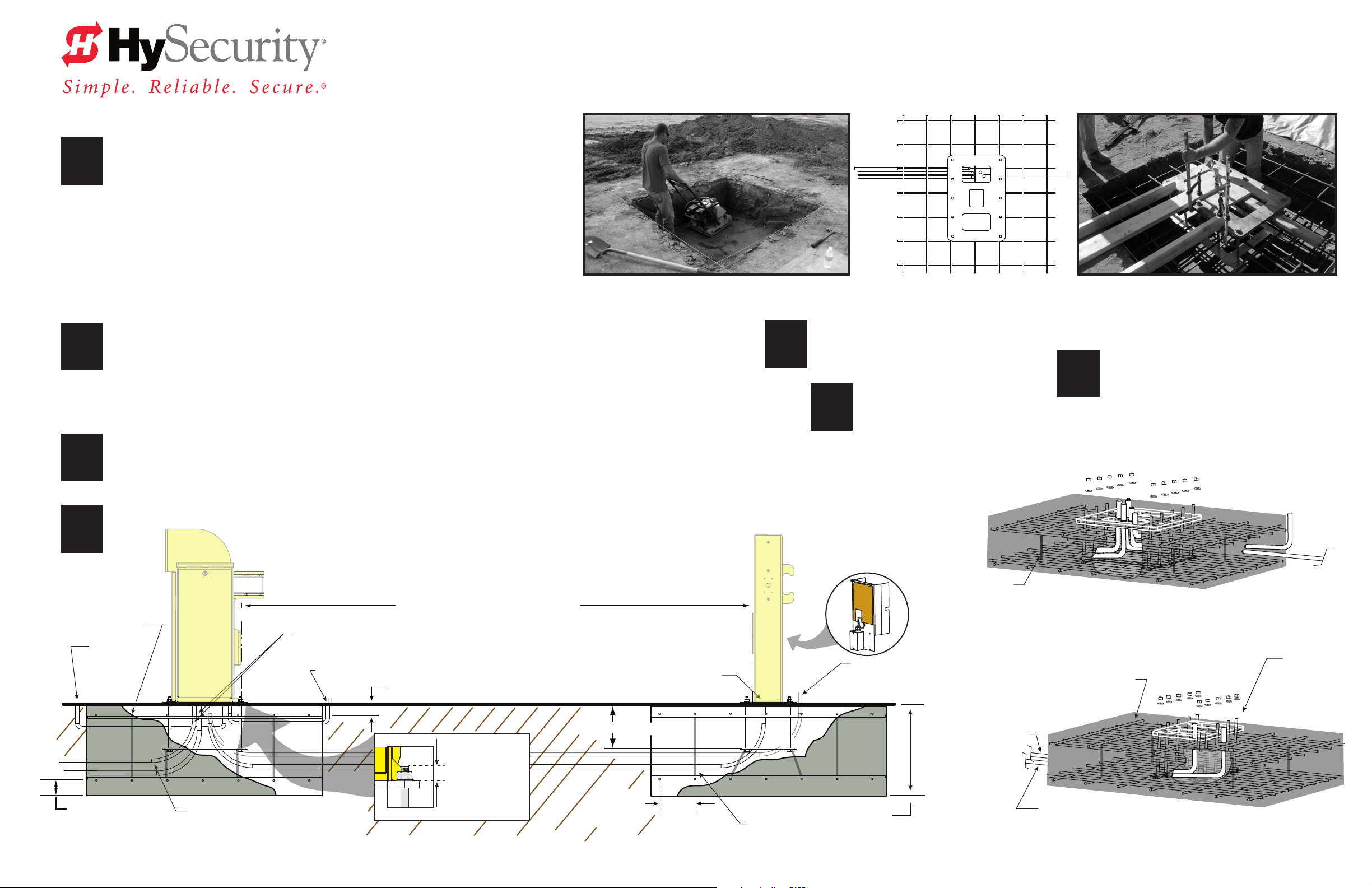
1
To make sure the stability of the StrongArm M30™ Crash Rated Fortied Barrier Arm,
the foundation must be constructed in accordance with the following guidelines:
• Excavate a hole for the foundation to house the rebar mats and anchor bolt assemblies.
Soil compression under and around the foundation shall be compacted to
a soil density of 95% of standard proctor (ASTM-698).
• Add gravel where necessary to ensure a solid soil base. Soil must be stable and
adequate to support the weight of the foundation.
IMPORTANT: Softer soils require a larger footing. Employ the services of a structural or
civil engineer for site specic considerations. In Northern latitudes, consider the frost line.
M30 INSTALL FOUNDATION
Soil Density compacted to 95% per ASTM-698 Aligning Rebar & Anchor CagePlan View: Pivot Post Template
Measure and lay conduit:
• Two separate 1-inch diameter conduits for the high voltage power and low voltage power controls.
2
3
• Conduit for vehicle loop wires. One separate conduit for each vehicle loop installed.
• Separate conduit for Earth ground.
• Appropriately-sized conduit between the operator Pivot Post and Catch Post for optional items such as:
thru beam photo eye, trac light, Mag Lock, or heater.
Lay rebar mat pattern 7 by 7 at 10-inch on center (OC).
Use #5 (⅝ inch) rebar: 10 lengths of 20 ft. (6m)
Cut 28 pieces of rebar 5½ ft long (168cm).
For the vertical pieces, cut 8 pieces of rebar 19 inches long (48cm).
Install the anchor bolt assemblies as shown.
4
Pivot Post
Rebar
verticals (4x)
Conduit
for Earth
Ground
3 inch (76 mm)
Bottom of rebar
CLEAR OPENING
Provide separate conduits for
High voltage & Low voltage power.
Conduit for Loops
2 inch Top of rebar (51 mm)
Correct
thread
height
extends approx.
1⅜ in. (35 mm)
Tip:
Tack weld base of anchor
cage to lower rebar (4x). Keeps the base of cage from oating when pouring the concrete.
above base
Conduit for optional items:
photo eye, traffic light
or Mag Lock
12 inch (30 cm)
Dim shown to bottom of plate
10 inch O.C.
(25 cm)
5
Heater
option
Rebar
verticals (4x)
Re-measure and adjust to
correct mis-alignment issues.
Ensure anchor cage location
6
is maintained while
pouring the concrete. See Tip.
Foundation dimensions:
Minimum 6 x 6 x 2 ft
(183 x 183 x 61 cm)
Catch Post
19 inch (48 cm)
Rebar verticals (4x)
Conduit for 240V
high voltage line.
Heater option.
Conduit for hard-wired
photo eye, Mag Lock, or
traffic light options
24 in. (61 cm)
e concrete properties must be, at minimum
7
3000psi. A smooth nish is required so the
Pivot & Catch posts sit at, level, & plumb.
Rebar mats:
#5 rebar (⅝ inch)
Length: 5½ ft (168cm)
Pivot Post
Anchor cages include 10 anchor bolts, washers, and nuts.
Rebar mats:
#5 rebar (⅝ inch)
Length: 5½ ft (168cm)
Conduit for 240V
high voltage line.
Heater option.
Catch Post
¾ in. bolts
15 in. length
(38 cm)
© 2013 www.hysecurity.com Page 3
StrongArm M30 Installation & Assembly - Foundation, Conduit, Anchor Cage D0432 Rev D
Page 6
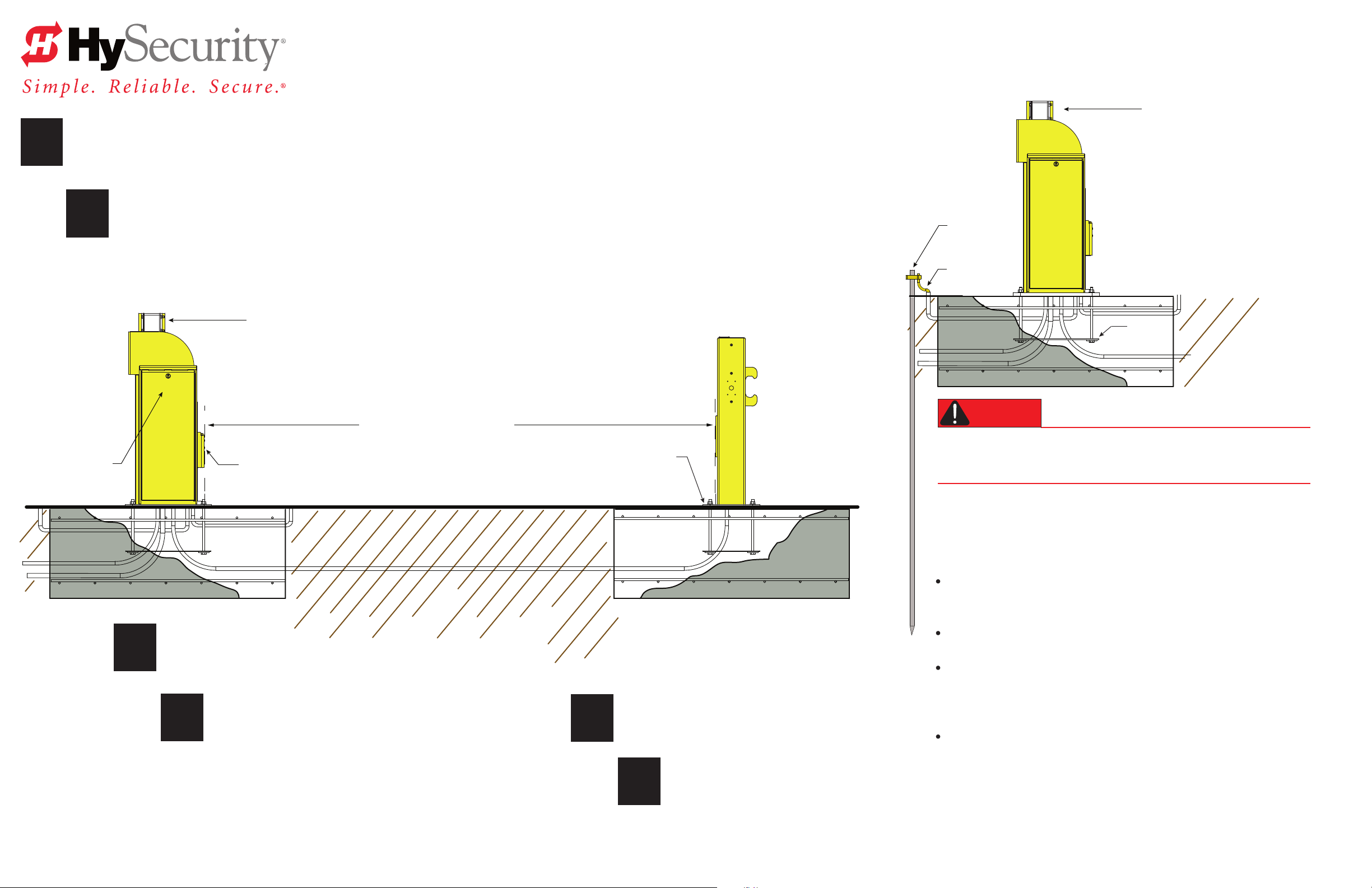
1
When the concrete has suciently hardened,
remove the templates.
M30 INSTALL POSTS & GROUND
M30 Arm Saddle
(Restraining strap - not shown)
Place the Pivot and Catch posts over their respective
2
Pivot Post Catch Post
Hydraulics cover
conduit and anchor bolt assemblies.
NOTE: Make sure to install the StrongArm M30 Crash Barrier Arm
on a level surface. Both pivot and catch posts must be plumb, level and
on grade with the roadway surface. Slope drainage ¼-inch per foot within 2 feet of the operator.
(2 cm per meter)
M30 Arm Saddle
(Restraining strap - not shown)
CLEAR OPENING
Lower Pivot Mount
Anchor plate
Pivot Post
Ground rod
6 AWG
Anchor
plate
DANGER
e potential for lightning discharge exists with all gates, barrier arms,
fences, and gate operators. National Electric Code (NEC) requires a
separate earth ground in addition to the required equipment ground.
For earth grounding requirements in the U.S.A., refer to the National
Fire Protection Association (NFPA) 780 - Standard for the Installation of
Lightning Protection Systems.
Highlights of the standard include:
e ground rod must be UL listed copper-clad steel, solid copper,
hot-dipped galvanized steel, or stainless steel. Minimum requirements:
½ inch (13 mm) diameter and 8 feet (244 cm) in length.
Ensure the posts are plumb.
3
© 2013 www.hysecurity.com Page 4
Shim or grout as required.
Secure each anchor plate using the
ten washers and nuts provided for
4
each post. Torque to 200 ft ∙ lb (271 N∙m)
Install the grounding rod per local building codes.
5
Attach a large earth ground wire (6AWG)
6
StrongArm M30 Installation & Assembly - Install Posts & Ground D0432 Rev C
from the grounding rod to the lug nut on
the chassis. Feed the 6AWG wire from the
chassis to the earth ground rod.
e ground rod is driven into the earth (refer to local codes for proper
depth requirements).
e ground rod is electrically bonded to the chassis with a single length
of un-spliced 6AWG copper wire less than 3 feet (91cm) long. Due to the
large concrete foundation, make the neccessary adjustments to accomodate
for earth ground requirements.
Local jurisdictions may impose additional or dierent requirements
above the NEC and NFPA 780. Consult the local codes and regulations
regarding requirements in your area.
IMPORTANT: Properly grounding the gate operator is critical to gate
operator performance and the life of its electrical components. Use sucient
wire size during installation. If you do not ground the operator with a separate
earth ground rod, you risk voiding the Limited Warranty.
Page 7
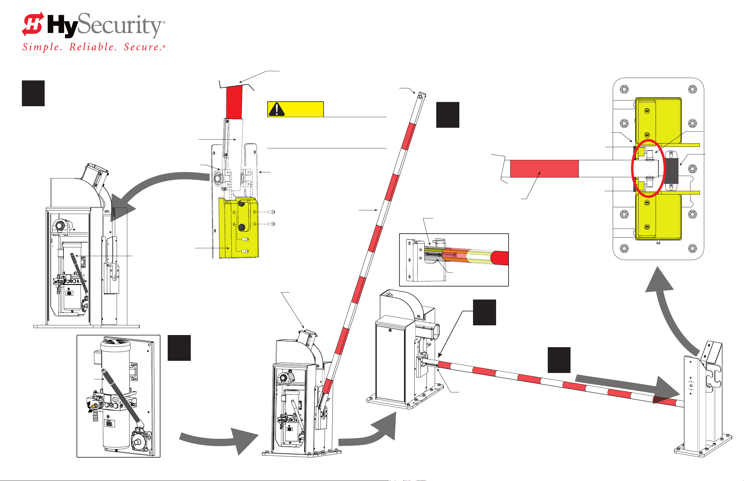
M30 ASSEMBLE BARRIER ARMS
Overhead View
Lower Arm
Lower Catch Pin
Mount the Lower Pivot Assembly (comprised of
the lower arm and bearings) into the Pivot Post
1
enclosure and secure the bearings to the Lower
Pivot Mount with the four buttonhead screws.
Pivot Post
Restraining strap
not shown
Hand Pump
Lower Pivot
Assembly
Bearings
Lower Pivot
Mount
Lower Catch Pin
CAUTION
Prevent potential injury! Remove the Lower Catch
Pin BEFORE installing the Lower Arm. If it is not
removed, it may slide out of the Lower Arm during
installation and drop onto personnel or equipment.
Loosen and remove the
four button head screws from the
bearings prior to installing the lower arm.
Lower Arm
5
Top Clamp
With the gap clearance set at
approximately ¾-inches between
the Lower Catch Pin and Post, securely
tighten the top clamp on the Lower Pivot Assembly.
¾-in. (2 cm) gap
¾-in. (2 cm) gap
Lower Arm
Lower
Catch Pin
Bumper
for M30
Arm
Pump
Handle
2
1
Open
Valve
2
Rest the Lower Arm on
the Catch Post, and then
use the manual pump
handle to lower the
M30 Arm saddle into a
horizontal position.
M30 Arm Saddle
Lower Pivot
Assembly
3
Lower Arm Saddle
Loosen, but DO NOT remove,
the six bolts and nuts on
the Lower Pivot Assembly.
Slide the Lower Arm to obtain
¾-inch clearance at the Catch Post.
4
Catch Post
© 2013 www.hysecurity.com Page 5
StrongArm M30 Installation & Assembly - Assemble Barrier Arms
D0432 Rev D
Page 8

INSTALL M30 ARM
1
Top clamp
Loosen and remove the ten top clamp
fasteners from the M30 Arm Saddle and
set the top clamp and nine fasteners aside.
Bottom clamp
(For clarity: Restraining
strap not shown)
Top clamp
M30 Arm Saddle
3
e M30 Arm is very heavy. Use proper lifting techniques
and obtain assistance to install the M30 Arm.
Rest the M30 Arm on the Catch Post’s bumper to
support its weight while you and your assistants
feed the restraining strap through the M30 Arm.
As you set the M30 Arm in its saddle, feed both sets of
the LED Arm Lights through the strain reliefs and into
the electronics side of the Pivot Post.
Strain relief holes in saddle for LED Arm Lights cable wiring
Double Restraining
Strap Loops
Shaft collar
End Cap
Shaft Collar
6
Front View
M30 End Cap
Adjust the Shaft Collars to hold the
pin in place and tighten the set screws
securely.
Position the End Cap and
secure it using four hex head
7
screws.
Upper Catch Pin
2
To stabilize the bottom clamp, return
one bolt and nut to the front edge of
the saddle. Keep the bolt loose while
installing the straps and aligning the
upper catch pin.
Bolt & washer
M30 Arm Saddle
Restraining strap
Bolt & nut
(Temporary
placement)
4
Bumper
Rest the M30 Arm
in its saddle and on
the Catch Post
bumper.
Double Restraining
Strap Loops
As you slide the Upper Catch Pin
through the end of the M30 Arm,
5
place both of the strap loops around
the Upper Catch Pin.
Tip:
Stretch the strap
using a 2 x 4
(100 x 50)
for leverage.
Upper
Catch
Pin
3/4 in.
(2 cm)
Side View
Restraining Straps
Cut away view
© 2013 www.hysecurity.com
Page 6StrongArm M30 Installation & Assembly - Link Arms and Install Trac Light D0432 Rev D
Page 9
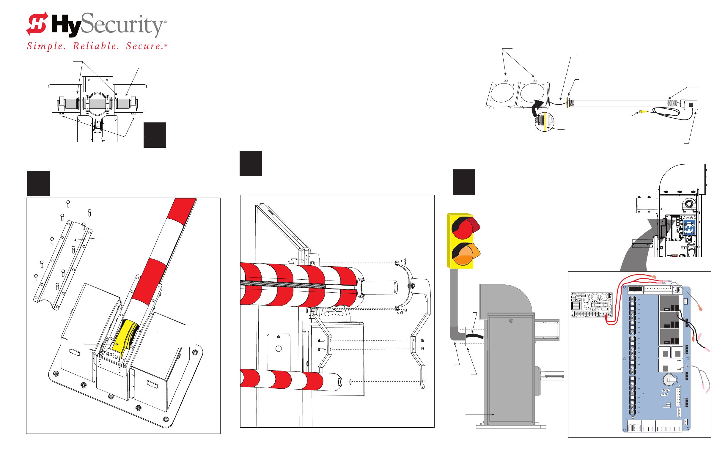
Rubber bushings
SID
R
D
Replace the Top Clamp and ten fasteners.
Tighten securely to 75 ft∙lbs (102 N∙m).
2
Rear View
Upper Pivot Pin
Bearing screws (4x)
Torque to 150 ft∙lb. (203 N∙m)
1
M30 LINK ARMS & INSTALL LIGHT
Open Traffic Light
access panels
Wire (Tape the ends of the wire to feed
through the pipe and elbow.)
Lock nut and bronze toothed washer
Taped end
Traffic light chassis
C
Pipe
Threaded
Elbow
3
Assemble the Arm Linkage as shown in the illustration.
Tighten the fasteners securely using two box end wrenches.
Tip: Have an assistant, manually raise the M30 Arm so it clears
the Catch Post and provides easier access to the Arm Linkage fasteners.
4
A
Secure pipe
B
inside access panel
with 1 large rubber washer,
1 silver washer, and 1 nut.
Assemble the Trac Light:
A. Open the Trac Lights access panels and feed
the wire through the pipe (remove the threaded
elbow if necessary).
Top clamp
Restraining
strap
LED Cable Connections
LED Arm Light
cable wire
Arm Linkage
B. Secure the pipe inside the access panel with the
fasteners shown and tighten them securely.
C. Replace the threaded elbow.
D. Connect the trac and LED arm lights to the
Smart Touch Controller. Wires are color-coded.
Match spade and bullet connectors.
Traffic Light
D
Wire
Elbow
Bracket
Feed wires
through hole in
chassis & route
through conduit to the Smart Touch Controller.
Connect wires
(black to black,
white to white, &
red to red).
Bundle and tie
wrap all the wires
above the display
keypad’s white
box.
NOTE: The wiring
harness for
2 trac lights is
not shown.
DRIVE
STOP BUTTON
1
2
OPEN BUTTON
3
CLOSE BUTTON
REMOTE OPEN AND
4
RADIO CONTROL
5
OPEN/CLOSE
OPEN PARTIAL
6
INTERLOCK OPEN
7
TIME CLOCK OPEN
FREE EXIT DETECTOR
8
DISABLE EXIT DETECTOR
9
DISABLE CLOSE TIMER
INSIDE OBSTRUCTION
10
VEHICLE DETECTOR
OUTSIDE OBSTRUCTION
11
VEHICLE DETECTOR
SHADOW/RESET
12
VEHICLE DETECTOR
EDGE SENSOR
14
PHOTO EYE POWER
24 VOLTS COMMON
PHOTO EYE POWER
15
DO NOT USE
16
PHOTO EYE
17
OPEN DIRECTION
DO NOT USE
18
PHOTO EYE
19
CLOSE DIRECTION
20
DO NOT USE
CHARGER
21
AC LOSS
SPARE INPUT
22
EMERG CLOSE
23
FIRE DEPT OPEN
24
LED
LIMITDUAL GATE
RPM
COMCOMAB
POWER
USER 3
HySecurity
MX000585
VERSION
S/N
Smart Touch Controller
RADIO OPTIONS
Hy
Security
®
Smart Touch Controller
Open
Reset
Previous
Close
Next
Green = Operate
Yellow = Program
Red = Fault
Stop
Program
Select
I ON
RS485
STOP/BUZZER
MOTORUSER 1
FREE
EXIT
USER 2
INSIDE
OBSTR
OUTSIDE
OBSTR
COM
NO
VEHICLE DETECTORVEHICLE DETECTORVEHICLE DETECTOR
STATUS
SHADOW
RESET
DISPLAY
VEHICLE DETECTOR
RS232
WIEGAND
COMOPEN EDGE+24V +24V
© 2013 www.hysecurity.com
StrongArm M30 Installation & Assembly - Link Arms and Install Trac Light D0432 Rev D
Page 7
Page 10

DANGER
M30 COMPLETE THE INSTALLATION
Turn OFF AC power at the source (circuit breaker panel) before accessing the wires in the StrongArm M30
junction box. Follow facility Lock Out/Tag Out procedures. Make sure all power switches are in the OFF
position. Follow all electrical code standards and regulations.
Connect to Power: ree wires and a ground are available for connection to a 3 Phase power source (3Ø).
Loosen the screws on the power module to open the wire slots at the top and bottom.
1
3Ø supply power connection shown
NOTE: 1Ø optional: Omit wire (do not connect) to L2 wire if supply power is 1Ø.
L1 L2 L3
I ON
I ON
ON
OFF
Directional power switch
Top screws: Loosen and
open wire slots.
Disconnect Switch
(Not to scale)
3
Install entrapment shield: Remove the six hex head screws and fender washers
from the Catch posts and use them to secure the Entrapment Shield as shown.
Tighten all six screws using a 7/32 hex key.
Ground
T1 T3T2
Conduit
Connect AC Power:
2
NOTE: Wiring of gate operators must conform to NEC standards
and comply with all local codes. When the installation is compliant and
complete, turn on AC power at the source and power module.
Place the incoming power wires
into their appropriate slots.
Attach the ground wires to the chassis.
Loosen screws and
open wire slots.
Jacket to VFD wire connections
4
Vent Plug
Breather Cap
Remove the Vent Plug.
Replace it with
the Breather Cap.
5
Torque Requirements:
Bolt size
¼ - 20 10 13
⅜ – 16 28 28
½ - 13 75 102
⅝ – 11 & ⅝ – 18 150 203
¾ - 10 200 271
(inches) ft∙lbs N∙m
© 2013 www.hysecurity.com Page 8
StrongArm M30 Installation & Assembly - Complete the Installation D0432 Rev D
Page 11

Page 12

DO432
800-321-9947 www.hysecurity.com
 Loading...